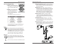
1
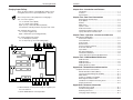
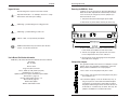
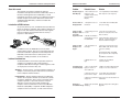
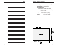
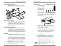
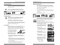
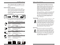
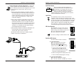
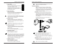
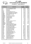
User’s Manual
RGB 202xi Interface
Includes
RGB 202 VS SL2
RGB 202 VTG
RGB 202 VS2
EXTRON ELECTRONICS/RGB SYSTEMS, INC.
1230 South Lewis Street, Anaheim, CA 92805
800.633.9876 714.491.1500 FAX 714.491.1517
USA
EXTRON ELECTRONICS, EUROPE
Beeldschermweg 6C, 3821 AH Amersfoort
+31.33.453.4040 FAX +31.33.453.4050
The Netherlands
EXTRON ELECTRONICS, ASIA
41B Kreta Ayer Road, Singapore 089003
+65.226.0015 FAX +65.226.0019
Singapore
EXTRON ELECTRONIC INFORMATION
EXTRONWEB™: www.extron.com
EXTRONFAX™: 714.491.0192
24-hour access — worldwide!
68-187-01
Printed in the USA
Precautions
Safety Instructions • English
This symbol is intended to alert the user of important
operating and maintenance (servicing) instructions
in the literature provided with the equipment.
This symbol is intended to alert the user of the
presence of uninsulated dangerous voltage within
the product's enclosure that may present a risk of
electric shock.
Caution
Read Instructions • Read and understand all safety and operating
instructions before using the equipment.
Retain Instructions • The safety instructions should be kept for future
reference.
Follow Warnings • Follow all warnings and instructions marked on the
equipment or in the user information.
Avoid Attachments • Do not use tools or attachments that are not
recommended by the equipment manufacturer because they may be
hazardous.
Consignes de Sécurité • Français
Ce symbole sert à avertir l’utilisateur que la
documentation fournie avec le matériel contient des
instructions importantes concernant l’exploitation
et la maintenance (réparation).
Ce symbole sert à avertir l’utilisateur de la présence
dans le boîtier de l’appareil de tensions dangereuses
non isolées posant des risques d’électrocution.
Attention
Lire les instructions• Prendre connaissance de toutes les consignes de
sécurité et d’exploitation avant d’utiliser le matériel.
Conserver les instructions• Ranger les consignes de sécurité afin de
pouvoir les consulter à l’avenir.
Respecter les avertissements • Observer tous les avertissements et
consignes marqués sur le matériel ou présentés dans la documentation
utilisateur.
Eviter les pièces de fixation • Ne pas utiliser de pièces de fixation ni
d’outils non recommandés par le fabricant du matériel car cela
risquerait de poser certains dangers.
Sicherheitsanleitungen • Deutsch
Dieses Symbol soll dem Benutzer in der im
Lieferumfang enthaltenen Dokumentation
besonders wichtige Hinweise zur Bedienung und
Wartung (Instandhaltung) geben.
Dieses Symbol soll den Benutzer darauf aufmerksam
machen, daß im Inneren des Gehäuses dieses
Produktes gefährliche Spannungen, die nicht isoliert
sind und die einen elektrischen Schock verursachen
können, herrschen.
Achtung
Lesen der Anleitungen • Bevor Sie das Gerät zum ersten Mal verwenden,
sollten Sie alle Sicherheits-und Bedienungsanleitungen genau
durchlesen und verstehen.
Aufbewahren der Anleitungen • Die Hinweise zur elektrischen Sicherheit
des Produktes sollten Sie aufbewahren, damit Sie im Bedarfsfall darauf
zurückgreifen können.
Befolgen der Warnhinweise • Befolgen Sie alle Warnhinweise und
Anleitungen auf dem Gerät oder in der Benutzerdokumentation.
Keine Zusatzgeräte • Verwenden Sie keine Werkzeuge oder Zusatzgeräte,
die nicht ausdrücklich vom Hersteller empfohlen wurden, da diese eine
Gefahrenquelle darstellen können.
Instrucciones de seguridad • Español
Este símbolo se utiliza para advertir al usuario sobre
instrucciones importantes de operación y
mantenimiento (o cambio de partes) que se desean
destacar en el contenido de la documentación
suministrada con los equipos.
Este símbolo se utiliza para advertir al usuario sobre
la presencia de elementos con voltaje peligroso sin
protección aislante, que puedan encontrarse dentro
de la caja o alojamiento del producto, y que puedan
representar riesgo de electrocución.
Precaucion
Leer las instrucciones • Leer y analizar todas las instrucciones de
operación y seguridad, antes de usar el equipo.
Conservar las instrucciones • Conservar las instrucciones de seguridad
para futura consulta.
Obedecer las advertencias • Todas las advertencias e instrucciones
marcadas en el equipo o en la documentación del usuario, deben ser
obedecidas.
Evitar el uso de accesorios • No usar herramientas o accesorios que no
sean especificamente recomendados por el fabricante, ya que podrian
implicar riesgos.
FCC Class A Notice
Warning
Power sources • This equipment should be operated only from the power source
indicated on the product. This equipment is intended to be used with a main
power system with a grounded (neutral) conductor. The third (grounding) pin is
a safety feature, do not attempt to bypass or disable it.
Power disconnection • To remove power from the equipment safely, remove all
power cords from the rear of the equipment, or the desktop power module (if
detachable), or from the power source receptacle (wall plug).
Power cord protection • Power cords should be routed so that they are not likely to
be stepped on or pinched by items placed upon or against them.
Servicing • Refer all servicing to qualified service personnel. There are no userserviceable parts inside. To prevent the risk of shock, do not attempt to service
this equipment yourself because opening or removing covers may expose you to
dangerous voltage or other hazards.
Slots and openings • If the equipment has slots or holes in the enclosure, these are
provided to prevent overheating of sensitive components inside. These openings
must never be blocked by other objects.
Lithium battery • There is a danger of explosion if battery is incorrectly replaced.
Replace it only with the same or equivalent type recommended by the
manufacturer. Dispose of used batteries according to the manufacturer's
instructions.
Avertissement
Alimentations• Ne faire fonctionner ce matériel qu’avec la source d’alimentation
indiquée sur l’appareil. Ce matériel doit être utilisé avec une alimentation
principale comportant un fil de terre (neutre). Le troisième contact (de mise à la
terre) constitue un dispositif de sécurité : n’essayez pas de la contourner ni de la
désactiver.
Déconnexion de l’alimentation• Pour mettre le matériel hors tension sans danger,
déconnectez tous les cordons d’alimentation de l’arrière de l’appareil ou du
module d’alimentation de bureau (s’il est amovible) ou encore de la prise secteur.
Protection du cordon d’alimentation • Acheminer les cordons d’alimentation de
manière à ce que personne ne risque de marcher dessus et à ce qu’ils ne soient
pas écrasés ou pincés par des objets.
Réparation-maintenance • Faire exécuter toutes les interventions de réparationmaintenance par un technicien qualifié. Aucun des éléments internes ne peut être
réparé par l’utilisateur. Afin d’éviter tout danger d’électrocution, l’utilisateur ne
doit pas essayer de procéder lui-même à ces opérations car l’ouverture ou le
retrait des couvercles risquent de l’exposer à de hautes tensions et autres dangers.
Fentes et orifices • Si le boîtier de l’appareil comporte des fentes ou des orifices,
ceux-ci servent à empêcher les composants internes sensibles de surchauffer. Ces
ouvertures ne doivent jamais être bloquées par des objets.
Lithium Batterie • Il a danger d'explosion s'll y a remplacment incorrect de la
batterie. Remplacer uniquement avec une batterie du meme type ou d'un ype
equivalent recommande par le constructeur. Mettre au reut les batteries usagees
conformement aux instructions du fabricant.
Vorsicht
Stromquellen • Dieses Gerät sollte nur über die auf dem Produkt angegebene
Stromquelle betrieben werden. Dieses Gerät wurde für eine Verwendung mit
einer Hauptstromleitung mit einem geerdeten (neutralen) Leiter konzipiert. Der
dritte Kontakt ist für einen Erdanschluß, und stellt eine Sicherheitsfunktion dar.
Diese sollte nicht umgangen oder außer Betrieb gesetzt werden.
Stromunterbrechung • Um das Gerät auf sichere Weise vom Netz zu trennen,
sollten Sie alle Netzkabel aus der Rückseite des Gerätes, aus der externen
Stomversorgung (falls dies möglich ist) oder aus der Wandsteckdose ziehen.
Schutz des Netzkabels • Netzkabel sollten stets so verlegt werden, daß sie nicht
im Weg liegen und niemand darauf treten kann oder Objekte darauf- oder
unmittelbar dagegengestellt werden können.
Wartung • Alle Wartungsmaßnahmen sollten nur von qualifiziertem
Servicepersonal durchgeführt werden. Die internen Komponenten des Gerätes
sind wartungsfrei. Zur Vermeidung eines elektrischen Schocks versuchen Sie in
keinem Fall, dieses Gerät selbst öffnen, da beim Entfernen der Abdeckungen die
Gefahr eines elektrischen Schlags und/oder andere Gefahren bestehen.
Schlitze und Öffnungen • Wenn das Gerät Schlitze oder Löcher im Gehäuse
aufweist, dienen diese zur Vermeidung einer Überhitzung der empfindlichen
Teile im Inneren. Diese Öffnungen dürfen niemals von anderen Objekten
blockiert werden.
Litium-Batterie • Explosionsgefahr, falls die Batterie nicht richtig ersetzt wird.
Ersetzen Sie verbrauchte Batterien nur durch den gleichen oder einen
vergleichbaren Batterietyp, der auch vom Hersteller empfohlen wird. Entsorgen
Sie verbrauchte Batterien bitte gemäß den Herstelleranweisungen.
Advertencia
Alimentación eléctrica • Este equipo debe conectarse únicamente a la fuente/tipo
de alimentación eléctrica indicada en el mismo. La alimentación eléctrica de este
equipo debe provenir de un sistema de distribución general con conductor
neutro a tierra. La tercera pata (puesta a tierra) es una medida de seguridad, no
puentearia ni eliminaria.
Desconexión de alimentación eléctrica • Para desconectar con seguridad la
acometida de alimentación eléctrica al equipo, desenchufar todos los cables de
alimentación en el panel trasero del equipo, o desenchufar el módulo de
alimentación (si fuera independiente), o desenchufar el cable del receptáculo de
la pared.
Protección del cables de alimentación • Los cables de alimentación eléctrica se
deben instalar en lugares donde no sean pisados ni apretados por objetos que se
puedan apoyar sobre ellos.
Reparaciones/mantenimiento • Solicitar siempre los servicios técnicos de personal
calificado. En el interior no hay partes a las que el usuario deba acceder. Para
evitar riesgo de electrocución, no intentar personalmente la reparación/
mantenimiento de este equipo, ya que al abrir o extraer las tapas puede quedar
expuesto a voltajes peligrosos u otros riesgos.
Ranuras y aberturas • Si el equipo posee ranuras o orificios en su caja/alojamiento,
es para evitar el sobrecalientamiento de componentes internos sensibles. Estas
aberturas nunca se deben obstruir con otros objetos.
Batería de litio • Existe riesgo de explosión si esta batería se coloca en la posición
incorrecta. Cambiar esta batería únicamente con el mismo tipo (o su equivalente)
recomendado por el fabricante. Desachar las baterías usadas siguiendo las
instrucciones del fabricante.
Note: This equipment has been tested and found to comply with the limits for a
Class A digital device, pursuant to part 15 of the FCC Rules. These limits are designed
to provide reasonable protection against harmful interference when the equipment is
operated in a commercial environment. This equipment generates, uses and can
radiate radio frequency energy and, if not installed and used in accordance with the
instruction manual, may cause harmful interference to radio communications.
Operation of this equipment in a residential area is likely to cause harmful
interference, in which case the user will be required to correct the interference at his
own expense.
Note: This unit was tested with shielded cables on the peripheral devices. Shielded
cables must be used with the unit to ensure compliance.
Extron’s Warranty
Extron Electronics warrants this product against defects in materials and
workmanship for a period of two years from the date of purchase. In the event of
malfunction during the warranty period attributable directly to faulty workmanship
and/or materials, Extron Electronics will, at its option, repair or replace said products
or components, to whatever extent it shall deem necessary to restore said product to
proper operating condition, provided that it is returned within the warranty period,
with proof of purchase and description of malfunction to:
USA, Canada, South
America, Central
America, and Asia:
Extron Electronics
1230 South Lewis Street
Anaheim, CA 92805, U.S.A.
Europe, Africa, and the
Middle East:
Extron Electronics, Europe
Beeldschermweg 6C
3821 AH Amersfoort
The Netherlands
This Limited Warranty does not apply if the fault has been caused by misuse,
improper handling care, electrical or mechanical abuse, abnormal operating conditions
or non-Extron authorized modification to the product.
If it has been determined that the product is defective, please call Extron and ask for an
Applications Engineer at (714) 491-1500 (USA), 31.33.453.4040 (Europe), or 65.226.0015
(Asia) to receive an RA# (Return Authorization number). This will begin the repair
process as quickly as possible.
Units must be returned insured, with shipping charges prepaid. If not insured, you
assume the risk of loss or damage during shipment. Returned units must include the
serial number and a description of the problem, as well as the name of the person to
contact in case there are any questions.
Extron Electronics makes no further warranties either expressed or implied with
respect to the product and its quality, performance, merchantability, or fitness for any
particular use. In no event will Extron Electronics be liable for direct, indirect, or
consequential damages resulting from any defect in this product even if Extron
Electronics has been advised of such damage.
Please note that laws vary from state to state and country to country, and that some
provisions of this warranty may not apply to you.
Accessing the Inside
Contents
Chapter One • Introduction and Features
Changing Jumper Settings
There are three jumpers in the RGB 202xi which can be
changed by the user for special applications. They are:
_ Note of the position of the jumper before changing it.
J23 – TTL colors (3-pins)
1 to 2 = 64 TTL Colors (EGA)
2 to 3 = 16 TTL Colors (CGA)
Open (2 only) = Automatic Detect (Default)
The interface normally produces the proper TTL colors.
J26 – Negative Sync (2-pins)
1 to 2 = Sync negative only.
Open = Automatic sync tracking (Default)
J31 – Video Clamp Time (3-pins)
1 to 2 = Backporch (normal)
2 to 3 = Sync Tip (1µ sec from leading edge)
Introduction ........................................................................... 1-1
Features .............................................................................. 1-2
Specifications ....................................................................... 1-5
Chapter Two • Rear Panel Connections
BNC Outputs with Auto Sync ................................................ 2-1
Sync Options ........................................................................ 2-1
Remote ................................................................................. 2-3
MBC Power .......................................................................... 2-3
Inputs 1 and 2 ....................................................................... 2-3
Audio Connections ............................................................... 2-4
Termination Switches (DIP 7 and 8) ..................................... 2-4
Laptop, Notebook or Portable Use ....................................... 2-5
Chapter Three • Operation • Controls and Indicators
Operating the RGB 202xi ............................................................. 3-1
Auto Power Indicator ............................................................ 3-1
Level and Boost .................................................................... 3-1
Peak Control ......................................................................... 3-2
Blue Enhance ....................................................................... 3-2
Picture Centering Controls ................................................... 3-3
Scan Rate Indicator .............................................................. 3-4
Input Switch .......................................................................... 3-4
DIP Switch Operation ........................................................... 3-4
Termination Guidelines ......................................................... 3-6
Laptop, Notebook and Portable Applications ........................ 3-7
Chapter Four • RGB 202 Model Differences
RGB 202 VTG ...................................................................... 4-1
RGB 202 VS2 ....................................................................... 4-2
RGB 202 VS SL2 .................................................................. 4-3
Making ShiftLock Cables ...................................................... 4-4
Appendix A • Related Parts and Accessories
Computer-to-Interface Connections ............................................. A-1
Monitor Breakout Cables (MBCs) ......................................... A-1
Internal Computer Wiring Kits (ICWKs) ................................ A-1
MBC Buffers ......................................................................... A-1
Partial List of MBCs and ICWKs ........................................... A-3
BNC High Resolution Cables ............................................... A-5
Handbook of Computer Interfacing Vol IV ............................ A-5
Remote Switch Box .............................................................. A-5
Appendix B • Reference Information
6. When finished, use the previous page as a guide to put
the cover back on.
7. Set the RGB 202xi for normal operation.
Page B-7
Extron • RGB 202xi Series • User’s Manual
Quick Reference Guide ........................................................ B-1
Troubleshooting Tables ......................................................... B-3
Removing the Cover ............................................................. B-6
Changing Jumper Settings ................................................... B-7
Extron • RGB 202xi Series • User’s Manual
Page i
Contents
Legend of Icons
Accessing the Inside
Removing the RGB 202xi Cover
The following icons may be used in this manual:
___ Important information – for example, an action or a step
that must be done before proceeding.
Jumpers are set at the factory to allow the RGB 202xi to
detect most video requirements automatically. However,
if it is necessary to change any of these jumpers you
must first remove cover.
1. Turn power off by disconnecting the power cable.
2. Disconnect any other cables that may be in the way.
___ A Warning – possible dangerous voltage present.
___ A Warning – possible damage could occur.
_ A Note, a Hint, or a Tip that may be helpful.
__ Additional information may be referenced in another
section, or in another document.
3. Use a small Phillips screwdriver to remove the four (4)
screws inside each rubber foot. Put these aside.
4. Turn the case upright. The top half of the case is the
cover. Pull upward on the cover to remove it.
User’s Manual Part Number Information
RGB 202xi, 202 VTG, 202 VS2 and 202 VS SL2 User’s Manual
68-187-01
Rev. A, 69-01
Rev B, 79-01
Page 4-4 cable connector
Rev C, 89-05 (for CD), 89-07 (for print)
Updated specs on page 1-5
Update inside cover styles and manual part number.
Rev D, 89-11, page 1-5
Change output video range to 1.2.
Rev E, 08-99, page 2-1
Remote description.
Written and trinted in USA.
Page ii
Extron • RGB 202xi Series • User’s Manual
5. Use the picture on the facing page locate the jumper
that needs to be changed.
Configuration Jumpers
The general illustration here shows an example of a 3-pin
jumper. These are sometimes called “Bergs”. There are
three possible combinations for a 3-pin jumper:
Pins 1 and 2 – Press the jumper onto pins 1 and 2.
Pins 2 and 3 – put the open end of the jumper over pins 2
and 3 and press on.
No connections (Open) – This can be done any way, as
long as no pins are connected. Three different Open
connections are shown here. Connecting one side of
the jumper and leaving the other contact off the end, or
off the side, is a common way to do this. This way, the
jumper is available if it is needed in the future.
Extron • RGB 202xi Series • User’s Manual
Page B-6
Troubleshooting
Reference Information
Problem
Probable Cause
Auto Power LED
not illuminating.
1. Incorrect Extron
1. Check that the MBC cables are
MBC cable being used. installed correctly.
Solution
2. Interface is not
2. Make sure computer is ON and
receiving a sync signal MBC cable is properly connected.
from the computer.
3. Input selection
switch is set to wrong
input.
3. Change the position of the Input
switch on the Front Panel.
Auto Power LED
stays on all the
time.
1. Auto Power defeat
Dip Switch #4 is on.
1. Turn Dip Switch #4 OFF.
Video on Data
Display is
hooking, or
bending.
1. Serration Pulses are 1. Turn switch #2 ON to remove
not required.
Serration Pulses.
2. Vertical Sync Pulse
width needs to be
wider.
2. Turn switch #4 ON to increase
the Vertical Sync pulse width.
3. Vertical Shift out of
proper alignment.
3. Adjust Vertical Positioning.
No Vertical Sync. 1. Interface may be
outputting separate
H&V sync.
1. Set switch #3 OFF to allow
Auto sync.
Computer boots
up black and
white instead of
color.
1. Turn computer power OFF, set
the appropriate termination switch
(#7 for Input #1 or #8 for Input #2)
ON and re-boot computer.
RGB 202xi, RGB 202 VTG,
RGB 202 VS2 and RGB 202 VS SL2
User’s Manual
1
Chapter One
Introduction
Features
1. No Termination to
computer video output
before computer is
turned on.
The Blue Video is 1. Blue Enhancement 1. Adjusting the Blue Enhancenot the correct
adjustment is not in the ment knob counterclockwise to
shade of blue for correct position.
reduce the Blue Enhancement.
TTL computer
signal.
VGA signal does 1. Projection device/
1. Set Dip Switch #3 ON and run
not fill screen
polarity not tracking all separate H&V output to projector
between modes. changes of VGA
or monitor.
through composite sync
output.
Page B-5
Extron • RGB 202xi Series • User’s Manual
Specifications
Extron • RGB 202xi Series • User’s Manual
Introduction • Features and Specifications
About this manual
Reference Information
Problem
This manual was written to explain the features,
installation and operation of Extron’s RGB 202xi series of
interfaces. Although the name “RGB 202xi” is used
throughout the manual, it refers to four different interface
models. Chapter 4 covers the differences between the
standard model RGB 202xi and those models with
special features.
As you may know by now, an RGB interface provides the
means for getting a computer video output to display on a
large screen. The interface must take the video signals
from the computer and transform them for use by a
projector or data monitor.
In addition to this, the RGB 202xi has many other
enhancement features. This user’s manual provides the
technical information required to install and operate the
RGB 202xi Universal Interface. Some places in this
manual it is simply referred to as the “interface”.
1. Computer Source is
Interlaced.
1. Turn DIP switch #1 ON (LCD
sync processing).
Image on Data
1. Input voltage level is
Display is dim or too low.
not at full
brightness level. 2. Double Termination
at that input (1 or 2) of
the RGB 202xi.
1. Increase level using Level
Control on front panel. Turn the
knob clockwise.
Image on Data
Display is too
bright.
1. No Termination for
that input.
1. Connect a local monitor to the
Extron MBC cable monitor input
connector (female).
or Set termination DIP switch ON
(#7 for Input #1; #8 for Input #2).
or See MBC documentation.
2. Output level is too
high.
2. Adjust the Level/Boost
counterclockwise.
1. Sync on Green with
high sync levels on
short cable runs.
1. Make sure that Peaking Control
is fully ccw for short cable runs.
Interface Considerations
As illustrated above, the interface operates between a
computer (or computers) and a video projector.
Computers differ both in the type of video signals as well
as the physical connectors they use.
Adapters – For this reason, a universal interface requires an
adapter to match the physical and electrical connections
of the computer and the interface.
Local Monitor – Another thing that must be considered is
whether the computer's monitor (“local monitor”) will be
used in the application. This is more convenient for the
computer operator, or presenter because it may be
difficult to see the big screen while operating the
computer. If the local monitor is to be used, a Monitor
Breakout Cable (MBC) is required. An MBC adapts the
computer to the local monitor, as well as the interface.
Page 1-1
Extron • RGB 202xi Series • User’s Manual
Solution
Double image on 1. The Horizontal scan 1. Incompatibility of Data Display
Data Display.
frequency of the
with computer scan frequency.
computer may be twice
that of the Data
Display.
Vertical Jitter of
Displayed text.
Introduction to RGB Interfaces
Probable Cause
Troubleshooting
Unstable image
on Data Display
2. Set termination switch (#7 for
Input #1, or #8 for Input #2) on
Rear Panel OFF for High Z.
2. Serration Pulses are 2. Turn DIP switch (#5) ON to
present at the output.
remove the Serration Pulses.
3. Signal not terminated 3. See projector documentation on
at projector.
termination.
Severely or
Signal needs horizontal Change Jumper #31 setting (See
unreadable image clamping.
page B8.
Extron • RGB 202xi Series • User’s Manual
Page B-4
Troubleshooting
Reference Information
Due to the number of different types of Data Projectors
and Data Monitors currently on the market, each with
different characteristics, no specific data display device
was used to generate this troubleshooting information. If
you have a concern or would like to know any special or
unusual characteristic of your particular display, please
call Extron.
Problem
Probable Cause
No image on Data 1. Power Connections
Display (projector not being made.
or monitor).
Solution
1. Check to make sure power is
being supplied to the computer,
monitor, interface and Data
Display (and MBC cable if
required).
2. Data Display not set
for Analog signal.
2. Check to confirm that Data
Display input settings are for
Analog.
3. Cables not connected.
3. Check and secure all cable
connections.
4. Horizontal or Vertical 4. Turn DIP switch #1 ON to check
phase is shifted too far centering reference.
in one direction.
5. Level Control turned
down too low on
interface.
5. Adjust Level Control to the
middle position.
6. Sync on Green
output from interface.
6. Set Data Display for an input of
Sync on Green, or turn Dip switch
#2 on to defeat Sync on Green
and #3 ON to use Auto Sync.
7. Input select switch
on interface is not set
correctly.
7. Make sure that the RGB 202xi
Input Select Switch is in the
correct position (Input #1 for
Analog/TTL, Input #2 for Analog/
ECL signals).
8. Contrast too low on
data display.
8. Increase contrast adjustment on
monitor or projector.
Introduction • Features and Specifications
Features
The RGB 202xi provides enhancement features to
improve the performance of the connected presentation
monitor or projector. These features are listed below and
described on the following pages.
•
•
•
•
•
•
•
•
•
•
•
•
•
•
•
•
•
•
300 MHz Bandwidth
15-150 kHz Compatible
Level and Boost Control
Peaking (Sharpness)
LCD Sync Processing
Auto Power
LCD Frequency Readout
Horizontal Centering Control
Vertical Centering Control
Blue Enhance Control
2 Universal Inputs
Input Termination Switches
Serration Pulse Removal
Sync Stripping
Two-Input Switching
Audio Interface
Automatic Sync Output: RGsB, RGBS or RGBHV
Internal Power Supply
Features in other RGB 202 models
RGB 202 VTG
• Built-in Video Test Generator
RGB 202 VS2
• Built-in VideoShift™
RGB 202 VS SL2
• Built-in VideoShift™ and ShiftLock™
__ Operational differences between these models and the
RGB 202xi are covered in Chapter 4.
_ Some monitors and projectors do require specialized
settings with the interface. Therefore, if you experience
any trouble, call Extron Tech Support at 714-491-1500.
Page B-3
Extron • RGB 202xi Series • User’s Manual
Extron • RGB 202xi Series • User’s Manual
Page 1-2
Introduction • Features and Specifications
Reference Information
Features Defined
Quick Reference Guide
1
Auto Power – In normal operation, the RGB 202xi is “green”
or in “power saver mode” because it turns on only when it
is needed. If it senses computer sync on its selected
input, the RGB 202xi turns ON. Also, when the selected
input senses no sync from that computer, it turns itself
OFF. The LED lights when the RGB 202xi power is on.
Level and Boost – This control is similar to a contrast
adjustment on a data monitor, which is used to adjust the
brightness and contrast of the displayed image. This
feature is also used to boost the output signal to a
maximum of 1.45 volts peak to peak to compensate for
losses of signal level or picture contrast due to cable
length. Output cable lengths of up to 1000 feet can be
used by adjusting this feature properly. The result is also
dependent on signal frequency.
Peaking (Sharpness) Control – This control is similar to the
sharpness control on a data monitor. Computer signals
will have a sharper image when adjusting the peaking,
regardless of the cable length. The peaking adjustment
compensates for mid and high frequency RGB Video
Bandwidth response in data monitors and projectors and
for signal loss due to cable capacitance.
Vertical Picture Centering (with Memory) – This
adjustment shifts the displayed image vertically on the
monitor or projector screen and remembers the settings
for both Input #1 and Input #2 separately.
Horizontal Picture Centering (with Memory) – This
adjustment is used to position the displayed image from
side to side on the screen. It also remembers the settings
for both Input #1 and Input #2 separately.
Scan Rate Readout – This LCD readout alternately displays
both the horizontal and vertical scan frequencies of the
selected computer signal.
REMOTE
2
Rear Panel Operation
Remote – Allows connection of a constant contact switch for remote selection
of Input #1 or #2 — only if Input switch on front panel is in #1 position.
MBC Power (2 connectors) – Connect Power plug(s) from up to 2 MBC
Buffer cables.
Input #1, Analog/TTL – Connect a video cable (or MBC) from any Analog or
TTL source.
Input #2, Analog/ECL – Connect video cable (or MBC) from any Analog or
ECL source.
Audio Input (1 & 2) – Connect to stereo audio sources for Input #1 and for
Input #2 (above).
Audio Output (L & R) – Connect to stereo left & right inputs of an external
audio system.
DIP Switches: (On = press right side of the switch, or away from the printed
switch numbers;
Off = press left side.)
1 - Off = Normal sync processing; On = Use LCD Sync processing
become inactive).
( &
2 - Off = Auto Sync detection; On = Auto Sync detection, but
No Sync on Green.
3 - On = Force separate Horizontal & Vertical Sync; Off = Auto Sync.
4 - Off = Auto Power detect; On = Auto Power defeat (forces power On).
5 - Off = Allow Serrations; On = remove Serrations.
6 - Off = Normal vertical sync width;
On = Vertical Sync approximately twice normal width.
7 - Off = High Z, Input #1; On = 75 ý Impedance, Input #1.
8 - Off = High Z, Input #2; On = 75 ý Impedance, Input #2.
Internal Power Supply – A 90-270 Volt, 50/60Hz internal
power supply is a standard feature of the RGB 202xi. No
setup is required for 50/60Hz power sources.
Blue Enhance (TTL) – Allows for mixing just the right
amount of blue video with the green video for displaying
blue text in a more readable blue-green color. This color
mixing affects only the displayed blue colors for TTL
Computer-video signals.
Page 1-3
Extron • RGB 202xi Series • User’s Manual
Extron • RGB 202xi Series • User’s Manual
Page B-2
Quick Reference Guide
Reference Information
Introduction • Features and Specifications
LCD Sync Processing – Exclusive to Extron, our LCD sync
processing makes the RGB 202xi work with CRT and
LCD based presentation displays.
Input Switch – The RGB 202xi interface can be connected
to the outputs of two computers at the same time, making
it a two-input switcher as well as an interface. The Input
switch is used to select which input source (#1 or #2) will
be displayed on the connected monitor or projector. Both
inputs are universal.
Front Panel Operation
Auto Power – Senses computer power and automatically turns the
RGB 202xi power ON.
Level Boost – Similar to a contrast control, this control raises and lowers the
output signal level from the original input level. e.g. a VGA input of 0.7v
peak-to-peak (p-p) can be adjusted for an output level of 0.3 to 0.8v p-p
(without boost). Within the boost (red) range, the output can be raised to
1.25v p-p.
Peak Control – Similar to a sharpness control, this control compensates for
mid and high frequency bandwidth response in data monitors and
projectors, and for signal losses due to cable capacitance. A sharper
image will be seen from most computers, regardless of cable length. For
long cables, the setting will probably be above the 50% level. Use your
visual judgement when using this adjustment.
Blue Enhance – Used with TTL signals (Input #1), allows the mixing of blue
with green for displaying text that is easier to read (blue-green color).
V Centering (vertical shift) – Moves image up or down on the display
screen. (Not active if DIP switch #1 is On) Memory stores settings to
keep image centered when switching inputs.
H Centering
(horizontal shift) – Moves image left or right on the display
screen. (Not active if DIP switch #1 is On.) Memory stores settings to
keep image centered when switching inputs.
LCD Screen – Alternately displays the horizontal and vertical frequencies of
the selected input.
H LED (red) – Lights when the LCD is displaying the horizontal
frequency of the selected input.
V LED (green) – Lights when the LCD is displaying the vertical
frequency of the selected input.
Input Switch – Used to select Input #1 or #2 (both video & audio) for output
from the RGB 202xi. (If in the #1 position, a constant contact switch may
be connected through the rear panel for remote switching.)
Termination Switches – These switches allow for 75 ohm
termination of the connected computer for either of the
two inputs. With this feature, an external termination
adapter is not required when using an Analog type
computer without an external local monitor (i.e., a
Laptop).
Automatic Sync Stripping – Sync is automatically stripped
off any incoming signal with sync on the red, green and
blue video channels. If desired, it can be added back to
the green output signal by the use of a dip switch, or Auto
Sync output detection.
Auto-Sync Output Detection – Automatically senses the
impedance on each BNC output, determines which ones
are being used and sends the proper sync output.
Audio Interface – The RGB 202xi includes a PC/computer
audio (600 ohm) to line-level audio (balanced) converter.
For computers that have a sound card, the audio
interface will select that audio input together with the
video (audio follow). The audio output can be connected
to an external stereo system.
Two-Input Switching – The RGB 202xi may be used as a
two input (one Analog/ECL and one Analog/TTL)
switcher. Input selecting can be done by the front panel
toggle switch or with an optional external switch plugged
into the rear panel remote connector. Audio input is
switched with video.
Local Monitor Compatibility – Using an MBC (Monitor
Breakout Cable) with the RGB 202xi allows for computer
monitor and large screen display image to operate at the
same time. This allows the presenter, or computer
operator to use the computer's (local) monitor while the
audience watches on the large screen.
Page B-1
Extron • RGB 202xi Series • User’s Manual
Extron • RGB 202xi Series • User’s Manual
Page 1-4
Introduction • Features and Specifications
Specifications
RGB 202xi, RGB 202 VTG,
RGB 202 VS2 and RGB 202 VS SL2
User’s Manual
Input Signal
Video:
Analog 0.3 to 1.45 V p-p
ECL
0.3 to 1.45 V p-p
TTL
2.7 to 7.00 V p-p
Audio:
Connector: 2.5 mm Stereo Jack
Impedance: High Z
Sync:
Output Signal
Video:
Sync:
Audio:
Separate Sync TTL/Analog
Horizontal Sync - Pos,/Neg.
Vertical Sync - Positive/Negative
Composite Sync TTL/Analog Level
Positive/Negative
Composite Sync on Green Video
0.3V p-p Negative
(video 0.7V p-p positive)
Analog .5 to 1.2V p-p
Auto Sync on Green
Composite Sync
(TTL level, 4V p-p)
(separate, negative-going)
Separate H and V Sync
(TTL level, 4v p-p)
Tracks polarity
(or force negative sync via jumper)
Connector: (2) 2.5 Stereo Jacks
Impedance: 600 ohms
Level: Line
RGB Video Output (RGB 202 VTG model)
RGB Video 1 v p-p
Peak White 0.7 - 0.714 v p-p above ground
Sync 0.272 - 0.375 v p-p below ground
Frequency Range
Horizontal:
Vertical:
15.5 kHz to 150 kHz
(Automatically)
40 Hz to 140 Hz
(Automatically)
LCD Scan-Rate Range
10 to 150 kHz Horizontal
30 to 200 Hz Vertical
RGB Video Bandwidth
300 MHz (-3dB) Bandwidth
Operating Temperature
Operating 0o to 50o C (31o to 122o F)
Storage -20o to 60o C (-4o to 140o F)
Page 1-5
Extron • RGB 202xi Series • User’s Manual
B
Appendix B
Reference and Troubleshooting
Quick Reference Guide
Troubleshooting
Removing the Cover
Changing Jumper Configurations
Extron • RGB 202xi Series • User’s Manual
Notes
Introduction • Features and Specifications
Humidity
5% to 95% non-condensing
Power Supply
90-270 Volt (auto-switchable)
Power Dissipation
12 Watts (Nominal)
Enclosure Dimensions
Plastic or Metal 9.75" W x 7" D x 1.75" H
(metric 24.8 W x 17.8 D x 4.5 H cm)
with rear BNCs D = 7.75" (See picture below.)
(metric 19.7 cm)
Weight
Plastic
Metal
Warranty
Page A-5
Extron • RGB 202xi Series • User’s Manual
2 lbs. 4 oz. (1.02 kg)
2 lbs. 10 oz. (1.2 kg)
2 years parts and labor
Extron • RGB 202xi Series • User’s Manual
Page 1-6
Notes
Related Parts and Accessories
BNC High Resolution Cables
Extron recommends High
Resolution BNC cables
with signal frequencies
greater than of 25 kHz or
when using a computer
with a frequency of 15135 kHz and running distances of 100 feet or more.
Extron High Resolution BNC cables are color-coded and
wrapped in a single jacket, and are listed below:
Cables
BNC-4/5-3'HR
BNC-4/5-6'HR
BNC-4/5-12'HR
BNC-4/5-25'HR
BNC-4/5-50'HR
BNC-4/5-75'HR
BNC-4/5-100'HR
BNC-4/5-150'HR
BNC-4/5-200'HR
BNC-4/5-250'HR
BNC-4/5-300'HR
BNC-4 #
26-210-01
26-210-02
26-210-03
26-210-04
26-210-05
26-210-06
26-210-07
26-210-08
26-210-09
26-210-54
26-210-53
BNC-5 # Feet/Meters
26-260-15
3/0.9
26-260-01
6/1.8
26-260-02
12/3.6
26-260-03
25/7.5
26-260-04
50/15
26-260-16
75/23
26-260-05
100/30
26-260-12
150/45
26-260-06
200/60
26-260-18
250/75
26-260-14
300/90
_ Bulk cable is available in lengths greater than 300 feet in
increments of 100 feet.
Handbook of Computer Interfacing Vol IV
This 3-ring binder contains detailed information on
computer-video applications, interfaces, scan converters,
as well as the following:
• Computer/Graphic Card cross reference charts
• Presentation Display Cross Reference charts
• Monitor Breakout Cables (MBCs)
– why they are needed and how to use them
• Monitor Identification (ID) Bits and Terminators
– what they do and how to make them work
• Laptop computer commands
• Glossary of terms
Call Extron to order part number 67-038-01.
Remote Switch Box
Remote Switch for the RGB 202xi Rear
Panel Remote jack with a 20’ cable.
The part number is 26-214-01.
Page 1-7
Extron • RGB 202xi Series • User’s Manual
Extron • RGB 202xi Series • User’s Manual
Page A-4
Related Parts and Accessories
Monitor Breakout Cables
Extron MBC “Monitor Breakout Cables” feature monitor
loop-through connector for providing local monitor
viewing. Below is a sample listing of Extron’s most
popular MBC and ICWK cables for use with the
RGB 202xi interface. Because this is only a partial listing,
please call Extron for any assistance to interface a
computer that may not be listed.
Part #
26-108-03
26-198-01
26-018-02
26-064-01
26-307-01
26-176-01
26-262-01
503-066
26-003-01
26-148-01
26-043-01
26-227-01
26-043-02
26-100-01
26-058-01
26-109-01
26-009-01
70-009-01
26-055-01
26-010-01
26-005-02
26-117-01
26-162-01
26-224-01
26-176-01
26-162-02
26-018-02
26-251-01
26-272-01
70-012-01
26-220-01
26-283-01
26-270-01
26-213-01
26-018-01
26-198-01
26-283-01
503-072
70-004-01
70-004-03
503-125
503-120
503-071
26-029-01
70-006-01
70-009-01
26-102-03
26-026-01
26-102-02
503-085
26-043-03
26-096-01
Page A-3
Cable Name
MBC AMIGA HR
MBC Apollo Mono
MBC Apple IIGS
MBC Burroughs Color
MBC Cornerstone DP120
DEC VR Terminals
MBC E/Machine Mono
MBC IBM 3151
MBC IBM 3161/63/91/96 Mono
MBC IBM 3162
MBC IBM 3164/79/92/97 Color
MBC IBM 3178C
MBC IBM 3192 Mono
MBC IBM 3193C
MBC IBM 3194 14" Display
MBC IBM 3194 Mono
MBC IBM 3270PC
MBC IBM 3472/3477 Infowindow Kit
MBC IBM PC Mono (MDA)
MBC IBM PCC (CGA/EGA)
MBC IBM PGA HR
MBC IBM PS/2 (Standard VGA Only)
MBC IBM VGA HR (Super VGA)
LBC IBM VGA HR (Laptop Cable)
PowerPC (IBM)
MBC IMAGE Adapter/A
MBC Mac/Quadra/PowerMac HR
MBC Memorex TELEX 1192
MBC NCD 14C/17C-CR/19C-G
MBC NCD 15B/16E/19R
MBC NeXt Buffer, Mono
NeXT Color
MBC RGB H&V (9 Pin to 5 BNC's)
MBC RGBS (9 Pin to 4 BNC’S)
RasterOps/SuperMac
MBC SUN/Apollo Mono
MBC Sun Sparc/SGI
ICWK DEC VT 320*
ICWK DEC 340 KIT
ICWK DEC VT 340
ICWK DEC VT 340 PLUS*
ICWK DEC VT 420*
ICWK HP 700/94*
ICWK IBM 3180
ICWK IBM 3476
IBM 3472/3477 Infowindow kit
ICWK MAC Classic RGB (9 pin)
ICWK MAC RGB (9 pin)
ICWK MAC SE RGB (9 pin)
ICWK Memorex/TELEX 1191*
ICWK Memorex C19A
ICWK Wsye 50
Hor. kHz
15.7
64.0
15.7
22.2
104
54 - 69
35.61
27.2
27.0
25.9
22.31
15.4
36.0
50.6
29.6
29.0
23.6
26.37
18.1
15.7-22
31.5
35
31.5-72
31.5-37
31 - 117
31-61
35-68
27.5
56-82
58-82
63.0
63
Varies
Varies
35 - 64
61-90
61-89
18.0
31.5
31.5
31.5
37.0
28.6
20.0
28.0
26.37
22.2
22.2
22.2
27.5
27.5
23.0
Ver. Hz
60
60-76
60
60
60
60
68
67.5
64.8
54.8
60
70
60
80
73
73
63
60
50
60
60
60-70
60-70
60-70
60 - 88
60 or 70
68
64.5
70
70
68
68
66
66-76
66-70
60
60
60
60
60 or 70
60
83
60
60
60
60
60
65.7
62.7
60
Extron • RGB 202xi Series • User’s Manual
RGB 202xi, RGB 202 VTG,
RGB 202 VS2 and RGB 202 VS SL2
User’s Manual
2
Chapter Two
Rear Panel Connections
Computer-Video Inputs 1 and 2
Remote Switch
MBC Power
Audio Input and Output
BNC Outputs
Sync Options
Extron • RGB 202xi Series • User’s Manual
Rear Panel Connections
Inputs 1 and 2 (Computer-Video)
Analog/TTL – This 9-pin input is for
any TTL Computer with a horizontal
scan frequency of 15-135 kHz. This
is for use with Extron MBC cables
only.
1
2
Analog/ECL – This 9-pin input is for
any analog or ECL input computer
source with a horizontal scan
frequency range between 15-135
kHz. This is for use with Extron
MBC cables only.
Pin assignments for the two connectors are:
Pin
Input #1 Signals
1.
Ground
2.
Red Prime
3.
Red Video
4.
Green Video/Sync
5.
Blue Video
6. Green Prime/Intensity
7.
Blue Prime
8.
Horizontal Sync
9.
Vertical Sync Input
Input #2 Signals
Ground
no connection
Red Video
Green Video/Sync
Blue Video
no connection
no connection
H Sync/Comp Sync
Vertical Sync
Switching between the two inputs is done by the Front
Panel switch (Chapter 3) or by the optional Remote
connector described above.
Related Parts and Accessories
MBC Mac/Quadra Buffer (26-339-01) – Buffers all Mac II,
Centris, Performa and Quadra computer output signals to
both the computer’s local monitor and the interface. No
other cable is required.
MBC RGB Buffer (26-176-01) – Buffers all computer or
Workstation outputs with Analog BNC type outputs from
15-135 kHz. Use the cable included with the computer to
connect to the buffer’s local monitor output and to the
Workstation monitor, but use Extron High Resolution
BNC-4 or BNC-5 style cable (or compatible) to connect
from the computer/workstation to the MBC RGB Buffer.
MBC Sparc Buffer (26-283-01) – Buffers all 13W3
connector type computer output signals to both the
computer’s local monitor and the interface. No other
cable is required. Compatible with Sun, SGI, DEC, NeXT
and many others.
MBC IBM PowerPC Buffer (26-384-01) – Uses 13W3
connector type and buffers computer output signals to
both the computer’s local monitor and the interface. No
other cable is required.
MBC VGA/XGA Buffer (26-338-01) – Buffers all VGA, Super
VGA, XGA, VESA, or XGA-2 computer output signals to
both the computer’s local monitor and the interface. No
other cable is required.
Remote
REMOTE
This 3.5 mm jack allows for remote switching between
Input #1 and Input #2. Remote operation requires a
latching switch and the front panel input switch must be
set to Input #1. When the remote switch is closed, input
#2 is selected; when it is open, input #1 is selected.
A 20 ft. cable with a remote switch is available from
Extron as an option. The part number is 26-214-01.
MBC Power
Some of Extron’s MBC High Resolution cables and
buffers require power. For those cables with a miniature
power plug attached, connect the power plug into either
of these two jacks.
___ Do not connect any other devices to the MBC power jacks.
Page 2-1
Extron • RGB 202xi Series • User’s Manual
Extron • RGB 202xi Series • User’s Manual
Page A-2
Related Parts and Accessories
Computer-to-Interface Connections
As illustrated below, there are many ways to connect a
computer to an interface, depending on the application.
This section discusses some of the possibilities.
COMPUTER
LOCAL MONITOR
COMPUTER OR PC
Rear Panel Connections
Audio Connections
The RGB 202xi provides
audio switching (together
with the video input) to
the audio output which is
connected to the user’s
audio equipment. The
user also supplies the
audio cables.
The Audio Interface is a
PC/computer audio (600 ý) to line-level audio (balanced)
converter. If the computer has a sound card, the input
switch on the RGB 202xi will select the audio with the
video (audio follow).
RGB 202xi TWO-INPUT
UNIVERSALINTERFACE
MBC (Monitor Breakout Cables)
Extron’s MBC monitor Breakout cables feature a monitor
loop-through connector to provide viewing both on the
local monitor and large screen display. MBC cables are
available for most computer manufacturers’ display
adapter cards and are attached directly the computer’s
display monitor output.
ICWK (Internal Computer Wiring Kit)
Extron ICWKs provide interfacing signals for computers
and terminals with no external video display output.
Internal video monitor signals are routed externally to the
computer, usually to a 9-pin connector. From the 9 pin
connector, a short cable is included with the kit for signal
transfer to the Extron interface 9-pin connector input.
MBC Buffers
Extron MBC Buffers isolate the computer’s video signal
and monitor from the Extron RGB 202xi interface, while
maintaining Video Bandwidth to the local monitor and the
interface. An example of an MBC buffer is shown on the
next page. Power is supplied to the buffers by the “MBC
Power” jacks located on the Rear Panel of the RGB 202xi
interface. The page A-3 shows a partial listings of the
most popular buffers; call Extron for a complete list.
HI-Res ECL Buffer (26-177-01) – Buffers all ECL type
signals and is used in conjunction with an MBC cable for
the computer being interfaced.
Page A-1
Extron • RGB 202xi Series • User’s Manual
Although the input and output audio connectors are
physically the same, they are used differently. See the
illustration and the following descriptions for the correct
wiring of audio inputs and outputs.
Audio Inputs – Connect the stereo audio sources for Input #1
and Input #2 (above). Each input connector includes
contacts for left and right stereo and a common/ground
connector. Input cables should be wired as follows:
• Stereo left to Tip (+) contact
• Stereo right to Ring (-) contact
• Both commons to Sleeve (Gnd) contact
Audio Output (Left & Right) – There is one audio output,
using separate connectors for left and right channels.
Connect the left and right output jacks to the inputs of an
external audio system. The 3-contact outputs can be
wired for balanced or unbalanced audio.
• For unbalanced audio, use Tip (+) and Sleeve (Gnd).
• For balanced audio, use Tip (+) and Ring (-).
_ Observe polarity when making connections to keep left
and right channels in phase.
Extron • RGB 202xi Series • User’s Manual
Page 2-2
Rear Panel Connections
_ This section describes function of each connector. Rear
Panel DIP switches are covered in Chapter 3.
RGB 202xi, RGB 202 VTG,
RGB 202 VS2 and RGB 202 VS SL2
User’s Manual
1
REMOTE
2
BNC Outputs with Auto Sync
The RGB 202xi converts all computer video to RGB
Analog signals, with outputs on the rear panel BNC
connectors. With all of the DIP switches in the OFF
position, the RGB 202xi is in the “Auto Sync” mode. This
means that it uses the BNC outputs that have an
impedance, by way of the attached cables. For example:
• If BNC connectors R, G and B
have cables attached (with 75ý
impedance) and H/V and V have
none, Auto Sync will use Sync
On Green as output.
• If BNC connectors R, G, B and
H/V have cables attached (with
impedance of 75ý for RGB and
less than 1ký for H/V), and V has
none, Auto Sync will use
Composite Sync as output.
• If BNC connectors R, G, B, H/V
and V have cables attached (with
75ý impedance for RGB and less
than 1ký for H/V and V), Auto
Sync will use Separate Horizontal
and Vertical Sync as output.
Sync Options
The Auto Sync feature can be altered by DIP switches
#1, #2 or #3 for specific sync processing.
Separate Horizontal and Vertical Sync - Separate
horizontal and vertical sync can be generated by setting
DIP switch #3 to the ON position. (See page 3-5.) When
using separate horizontal and vertical sync, the sync
polarity tracks the incoming polarity changes, unless
jumper 26 is set to force negative sync.
__ See Appendix B for special setup.
Page 2-3
Extron • RGB 202xi Series • User’s Manual
A
Appendix A
Related Parts and Accessories
Computer-to-Interface Connections
MBC (Monitor Breakout Cables)
High Resolution BNC Cables
Partial List of MBCs
Remote Switch Box
Extron • RGB 202xi Series • User’s Manual
RGB 202 Model Differences
Rear Panel Connections
Sync Polarity – VGA, for example, has three modes of
operation. Each of these modes has a different polarity
(positive or negative combinations) configuration. The
RGB 202xi tracks these mode polarity changes and
sends out the polarity exactly as it is came in. Thus, if
horizontal sync comes in positive and the vertical sync is
negative they will go out the same way. This sync
tracking only occurs when using the separate Horizontal
and Vertical sync output option (DIP switch #3) of the
RGB 202xi. (See Page B-8, jumper 26.)
Notes
Composite Sync (H/V) vs Sync on Green – Unless the H/V
output is terminated at 1ký or less, output sync will
automatically be on the green channel. Regardless of
termination impedance, composite sync is always present
at (H/HV) output, unless DIP switch #3 (separate H&V) is
ON, or the “V” Sync output is terminated with less than
1ký impedance. In these cases, separate horizontal sync
is present.
Nonstandard Termination – In the professional A/V and
Computer industries, the standard termination impedance
for R, G and B is 75 ý and anything less than 1ký for
sync. However, some data monitors or RGB switchers
may use other termination impedance values. In these
cases, it may be necessary to set Dip switch #2 to the
ON position to defeat Sync on Green. The interface will
then use composite sync (H/V).
_ Also, please note that many data monitors and projectors
do not automatically switch between sync on green and
composite sync (H/V). In these cases, make sure the
monitor or projector is set to the desired input
configuration.
LCD Display Devices – When using an LCD display, or if
the image has jitter, try turning DIP switch #1 ON. This
switch is explained on page 3-4.
__ See Appendix B for quick reference and troubleshooting
information.
__ See Chapter 4 for model differences.
Page 4-5
Extron • RGB 202xi Series • User’s Manual
Extron • RGB 202xi Series • User’s Manual
Page 2-4
Notes
RGB 202xi Model Differences
Making ShiftLock™ Cables
Extron supplies connectors for making ShiftLock cables;
the user supplies the cable. Twisted pair cable may be
used – up to 50 feet in length.
The illustration below shows the steps for a making a
cable using twisted pair. Do each step for both ends of
the cable. Make as many cables as required.
___ Although the color of the wire is not important, however
you must use the same wire color assignments for each
end of the cable.
1. Unscrew the Metal Case.
2. Identify the contacts, parts and connections.
Wire
Flex-Spring
___ The Plastic Insulator must be inside to prevent electrical
contact with the metal Case.
As shown here, the connectors have three contacts.
However, only the “Tip” and “Ring” contacts are used.
3. Insert the Metal Case (Insulator and flex Spring) over
the cable.
4. Strip the wires and attach them through the holes in the
contacts.
5. Solder both connections.
6. Bend the Tabs around the
Cable Jacket.
7. Press the wires and contacts inward to allow the
Insulator and Metal Case to
slide over easily.
___ Do not allow the contacts to touch each other.
8. Screw the Metal Case
onto the connector.
8
Connect the cables as shown on Page 4-3.
Page 2-5
Extron • RGB 202xi Series • User’s Manual
Extron • RGB 202xi Series • User’s Manual
Page 4-4
RGB 202 Model Differences
RGB 202 VS SL2 (VideoShift™ and ShiftLock™)
The VS SL2 model includes both VideoShift™ and
ShiftLock™ features. The VideoShift™ controls are on
the front panel and the ShiftLock™ controls are on the
back panel.
The VideoShift is the same as that described for the VS2
model.
The ShiftLock™
feature allows two
or more RGB 202
VS SL2 units to be
linked together,
such that one of the units controls the VideoShift for all. A
toggle switch on the back panel allows one to be set as
the “Master”. Each of any other units connected must be
set as “Slave”.
_ When the switch is set to “Slave”, the
VideoShift controls for that unit are
disabled.
1
IN
OUT
MASTER
SLAVE
2
Two connectors on the back panel
(see right) are used to connect the
Master and Slave(s).
3
Chapter Three
Setup example:
1. The Master unit will have a cable connected from its
“ShiftLock Out” to the
“ShiftLock In” port of the
first Slave. Its toggle
switch must be set to the
“Master” position.
1
IN
OUT
2. The first Slave will have a
cable from its “ShiftLock
Out” to the “ShiftLock In”
of the next Slave. Its
toggle switch must be set
to the “Slave” position.
3. Step #2 will repeat for
each Slave unit, except
that the last Slave (or the
only Slave), will have no
cable in its “ShiftLock Out” connector.
MASTER
SLAVE
2
Page 4-3
RGB 202xi, RGB 202 VTG,
RGB 202 VS2 and RGB 202 VS SL2
User’s Manual
Operation • Controls and Indicators
Auto Power
Level and Boost
Peaking
1
IN
OUT
MASTER
SLAVE
2
Blue Enhance
Vertical and Horizontal Centering
Scan-rate Indicator
1
2
IN
OUT
MASTER
SLAVE
Extron • RGB 202xi Series • User’s Manual
Input Switch
Rear Panel DIP Switches
Extron • RGB 202xi Series • User’s Manual
Operation • Controls and Indicators
Operating the RGB 202xi
RGB 202xi Model Differences
RGB 202 VS2 (VideoShift™)
This chapter covers the function of the controls and
indicators on the RGB 202xi, including some examples on
how they are used.
__ If there are any difficulties setting up for the desired
results, see Appendix B for troubleshooting information.
The VS2 model includes Extron’s VideoShift™ feature.
The front panel for the RGB 202 VS2 is shown below.
The section marked “VideoShift™” includes a 3-position
toggle switch to do the following:
• Off – disables the feature.
• Test – enables VideoShift™ at a rate fast enough to see
movement on the screen. Use this position to adjust the
shift range.
• Shift – enables the feature.
Auto Power Indicator
This LED lights when the RGB 202xi is powered ON.
“Auto Power” means that the computer signal will
automatically turn the RGB 202xi power on.
If the LED does not illuminate, check for computer
operation as well as cable and power connections.
If DIP switch #4 (rear panel) is On, the Auto Power detect
feature is disabled, forcing the power ON as long as it is
plugged to an active power source.
Level and Boost
This control is similar to a contrast adjustment on a data
monitor or projector. It can be used to increase the
brightness and contrast of the displayed image. Observe
the displayed image while using these adjustments.
Following are some examples
of approximate output levels,
with a computer input signal
(such as VGA) of .7 volts
peak to peak (p-p) and the
output is terminated at 75 ý.
1. With the knob in the minimum (counterclockwise)
position, the voltage output level will be approximately
0.5 volts p-p.
2. With the knob to the end of the level adjustment range
(at the top of the red line), the voltage output level will
be approximately the same level as the input (0.7 volts
p-p for this example).
When VideoShift™ is enabled, it prevents phosphor
“burn-in” by moving the displayed image around on the
screen. The movement is so slow that it cannot be
detected by the human eye.
VideoShift movement to the right, down, to the left, up,
etc. The distance of the shift, or movement depends upon
the Range setting. The vertical
shift is in number of lines while
the horizontal shift is in units of
time. Approximate settings are:
Minimum setting:
Vertical shift = 8 scan lines
(4 up and 4 down from center)
Horizontal shift = 0.1 µsec.
Mid-range setting:
Vertical shift = 16 scan lines
Horizontal shift = 0.68 µsec.
Maximum setting:
Vertical shift = 32 scan lines
Horizontal shift = 1.28 µsec.
The actual horizontal distance
will depend upon the video
format. Here are two examples
at maximum range:
SGI – 128 pixels
VGA3 – 64 pixels
3. At the full clockwise position (past the red line), the
output can be increased up to 1.45 volts p-p.
Page 3-1
Extron • RGB 202xi Series • User’s Manual
Extron • RGB 202xi Series • User’s Manual
Page 4-2
RGB 202xi Model Differences
There are three other models of the RGB 202xi, each of
which has additional features. This chapter covers only
those differences; all standard features are in the other
sections.
RGB 202 VTG (Video Test Generator)
This model includes some of the features of Extron’s
Video Test Generators. On the front panel (shown below)
there is a section marked “Mini VTG”. When the toggle
switch marked “202” and “VTG” is in the VTG position, a
test pattern is generated on the output of the RGB 202
VTG. In the “202” position, the interface functions as a
normal RGB 202xi.
Operation • Controls and Indicators
This Boost range (red) can compensate for losses of
signal level or picture contrast due to increased cable
length. Depending on cable specifications, 50% Boost
(middle of red line) may improve picture quality for cable
lengths shorter than 500 feet for all computer signals
between 15-135 kHz. Set the Boost at 100% (fully
clockwise) for cable lengths longer than 500 feet for all
computer signals 15-135 kHz. Always observe the
displayed image while using this adjustment.
Because the RGB 202xi is capable of driving signal cables
up to 1000 feet long (depending on the signal frequency),
Extron recommends using High Resolution, BNC type
coax cables. Standard RG59 cable is good for NTSC
video and low resolution computer RGB signals, but it
limits video quality on medium and high resolution
computer RGB signals.
Peaking Control
In the VTG mode, the rotary switch is used to select one
of four patterns for one of four display types. These are:
Quadrant Format
PixelxLine H.kHz V.Hz
1
VGA3
640x480 31.5 60
Position 1
Crosshatch pattern
Position 2
H Pattern, back and white
Position 3
8-level Split Grayscale pattern
Position 4
8-Color Bar pattern
2
MAC13
640x480
35
60
Position 5
Crosshatch pattern
Position 6
H Pattern, back and white
Position 7
8-level Split Grayscale pattern
Position 8
8-Color Bar pattern
3
VESA3
1024x768 48.4 60
Position 9
Crosshatch pattern
Position 10
H Pattern, back and white
Position 11
8-level Split Grayscale pattern
Position 12
8-Color Bar pattern
4
SGI
1280x1024 64
60
Position 13
Crosshatch pattern
Position 14
H Pattern, back and white
Position 15
8-level Split Grayscale pattern
Position 16
8-Color Bar pattern
The patterns are:
Crosshatch
H Pattern
Page 4-1
Grayscale
This control is similar to a sharpness adjustment on a data
monitor. A sharper image will result from adding some
peaking adjustment for all computer signals, regardless of
the cable length used. The Peak Control compensates for
mid and high frequency RGB Video Bandwidth response
in data monitors and projectors, as well as for signal loss
due to cable capacitance. On most cable lengths of 250
feet or more, set the Peak Control at 100% for optimum
picture quality (fully clockwise). Always observe the
displayed image while using this adjustment.
Blue Enhance
Because blue text is difficult to read, this adjustment
allows the user to improve on this by changing the color
slightly. The Blue Enhance adjustment allows for mixing
just the right amount of blue information with the green
signal to make the text a more readable, blue-green color.
This only occurs on TTL signals such as IBM 3179, CGA,
and EGA graphic cards. This adjustment will only affect
TTL signals (Input #1). Always observe the displayed
image while using this adjustment.
8-Color
Extron • RGB 202xi Series • User’s Manual
Extron • RGB 202xi Series • User’s Manual
Page 3-2
Operation • Controls and Indicators
Picture Centering Controls
These two knobs are used to make four
separate adjustments. The RGB 202xi has
memories for each of its two inputs. Turning a
knob not only moves the image but it also
stores that information in the memory for the
selected input. When switching between
inputs, or when power is OFF, each memory keeps the
centering information that was last set. This means that
centering for each of the two inputs need only be set
once for an application.
These two controls have no mechanical limits. Each
centering knob can be turned forever – in either direction.
Any time a Centering Control is turned, with the interface
power on, centering information is being stored. The
limits on how far the picture will move on the screen is
determined by software, and not by any mechanical limits
of the knob. There is no “reset”, you simply readjust.
Many projectors store picture centering information in
their memories based on frequency. When switching
between input sources that have the same frequency, the
image may not be perfectly centered. However, on the
RGB 202xi, centering adjustments are stored for each
input, regardless of frequency, thus assuring accurate
centering when switching between the two inputs.
Vertical ( ) – The Vertical Centering adjustment (also called
“Vertical Shift”) is used to move the image up and down
on the screen. Most data monitors and projectors don’t
have this adjustment and those that do may give
inconsistent results when switching between inputs. This
is a useful feature in an interface because Having a
Centering Control on the interface provides an easy way
to eliminate this problem.
_ To use the centering controls on the display device,
instead of those on the interface, set DIP switch #1 on the
rear of the RGB 202xi to the ON position.
Horizontal ( ) – The Horizontal Centering adjustment (also
called “Horizontal Shift”) is used to move the image from
side to side on the screen. As with Vertical Picture
Centering, this control can also be defeated (turned off)
by setting DIP switch #1 on the rear of the RGB 202xi to
the ON position.
Page 3-3
Extron • RGB 202xi Series • User’s Manual
RGB 202xi, RGB 202 VTG,
RGB 202 VS2 and RGB 202 VS SL2
User’s Manual
4
Chapter Four
RGB 202 Model Differences
RGB 202 VTG
(Video Test Generator)
RGB 202 VS2
(VideoShift™)
RGB 202 VS SL2
(VideoShift™ and ShiftLock™)
Extron • RGB 202xi Series • User’s Manual
Operation • Controls and Indicators
Laptop, Notebook or Portable Applications – Video from
these computers may be quite different from standard
PCs or Macs because they were designed to use an LCD
screen instead of a CRT monitor. Here are some
guidelines:
A) When using Laptop, Notebook or portable computers
with VGA outputs, the termination switch must be set to
75 ý for that input (#1 or #2) and all cable connections
must be made before turning the computer power ON
(unless using an LBC VGA cable, or using a VGA
Termination Adapter).
B) Most Laptop, Notebook and portable computers have
external video (CRT or RGB) ports but require special
keyboard commands to access or output the video to
this connector. See the User’s Guide that came with the
computer for instructions to activate this video port or
call Extron for a complete list of all Laptop, Notebook
and Portable keyboard commands.
C) Most portable computers with built-in LCD displays will
be deactivated (shut-off) automatically once the
external video port has been activated.
The illustration below shows how a Laptop computer
could be connected to an RGB 202xi.
Operation • Controls and Indicators
Scan Rate Indicator
This LCD readout alternately displays the
horizontal and vertical scan frequencies of the
selected input. To the right of the scan-rate
display, the red LED will illuminate indicating a
horizontal reading, and the green LED will
illuminate indicating a vertical reading. This frequency
readout is displayed in Hertz (Hz).
Input Switch
The RGB 202xi interface can be connected to two
computers at the same time, thus making it a two- input
switcher, as well as an interface. The input switch is used
to select which input source will be displayed on the data
monitor or projector. Used to select Input #1 or #2 (both
video & audio) for output from the RGB 202xi. When in
the #1 position, a constant contact switch may be
connected through the rear panel for remote switching.
DIP Switch Operation
The RGB 202xi uses the "rocker" type of
DIP switches. An example is shown here.
When looking at the switches from the rear:
On = press right side of the switch.
Off = press left side of the switch.
_ The factory setting for all DIP switches is Off.
Rear Panel DIP Switches
The DIP switches function as follows:
#1 - Sync Processing
Off = Use normal sync processing.
On = Use LCD Sync processing.
Centering controls ( and ) become
inactive. This switch may also be used:
a. To get a center reference point by
temporarily turning it ON, note the
picture centering, and then turn it OFF
and make centering adjustments.
b. When centering from the display device only.
c. If there is difficulty adjusting the centering.
#2 - Sync On Green Defeat
Off = Auto Sync detection is active.
On = Auto Sync detection, but No Sync on Green.
Page 3-7
Extron • RGB 202xi Series • User’s Manual
Extron • RGB 202xi Series • User’s Manual
Page 3-4
Operation • Controls and Indicators
#3 - Sync Output
Off = Auto Sync Processing.
On = Force separate Horizontal and Vertical
Sync output, regardless of cable
connections. This feature may be used when
the display device does not have a sync
impedance that is low enough to be detected
by the Auto Sync feature.
#4 - Auto Power Defeat
Off = Auto Power detect
On = Auto Power defeat forces RGB 202xi power On.
This turns the interface on permanently while it is
connected to an active AC power source.
___ This switch must be turned on before computer boot-up
when using any Extron Monitor Breakout Cables (MBCs)
that get power from the RGB 202xi.
#5 - Serration Pulses
Off = Allow Serration pulses on the composite sync
vertical sync interval. If not there, it will create them.
On = Remove serration pulses from the composite sync
vertical sync interval.
Operation • Controls and Indicators
__ If there are any difficulties getting the desired results, see
Appendix B for additional information.
Termination Guidelines
When connecting an interface to a computer’s video
output, it is necessary to provide the same termination
impedance for which those video circuits were designed.
The RGB 202xi provides the necessary termination for
any application. Following are some guidelines for using
termination switches #7 and #8.
MBC Cables – When using an Extron Monitor Breakout
Cable (MBC) with the computer’s local monitor attached,
set the Termination Switch for that input OFF (High
Impedance). When not using a computer local monitor or
when using a Laptop, set the switch for that input ON for
75 ý termination.
The illustration below shows a PC connected to an
RGB 202xi with a local monitor.
_ The RGB 202xi is unique in that it can remove serration
pulses, or it can create them if they are not present.
#6 - Vertical Sync Width
Vertical Sync pulse width depends upon the frequency
coming into the RGB 202xi. This switch allows this width
to be increased.
Off = Use normal vertical sync width.
On = Vertical Sync approximately twice normal width.
#7 - Impedance for Input 1
Off = High Impedance for Input #1
On = 75 ý Impedance for Input #1.
_ Use the OFF position when the video source is terminated
elsewhere, such as at the local monitor; use ON if the it is
not terminated elsewhere. If terminated elsewhere, and at
the interface, this is called "double termination" and will
send a weak signal to the display device. Guidelines for
using these switches are on following pages.
8 - Impedance for Input 2
Off = High Impedance for Input #2
On = 75 ý Impedance for Input #2.
The note above also applies for both Inputs.
Page 3-5
Extron • RGB 202xi Series • User’s Manual
_ Some computers need Monitor ID bit termination. An
external Termination Adapter may be required.
ICWKs – When using an Extron ICWK (Internal Computer
Wiring Kit), set the switch for that input to the ON position
for 75 ý termination.
MBC Buffers – When using Extron MBC Buffer cables, set
the impedance switch for that input (#7 for Input 1 or #8
for Input 2) to the OFF position for high impedance.
__ Page A-1 has more information on MBCs.
Extron • RGB 202xi Series • User’s Manual
Page 3-6