1
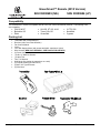
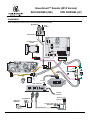
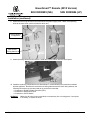
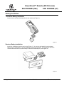
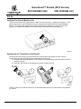
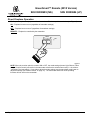
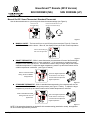
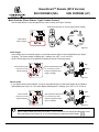
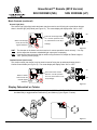
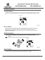
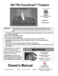
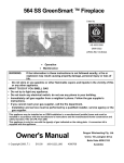
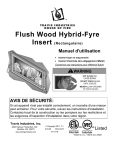
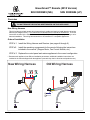
GreenSmart™ Remote (2010 Version) SKU 99300685 (NG) SKU 99300684 (LP) Overview This wiring harness attaches to the existing wire harness (unlike the older version). DO NOT REMOVE THE EXISTING WIRE HARNESS ON YOUR APPLIANCE. New Wiring Harness This kit includes a revised remote wiring harness that is smaller and easier to install than the old wiring harness (see diagram below). The instructions included with this kit should be followed first. Then the instructions included in the installation manual should be followed, omitting the steps pertaining to wireharness installation. This wiring harness works on all GreenSmart™ compatible appliances. Order of Installation STEP # 1 Install the Wiring Harness and Receiver (see pages 4 through 6). STEP #2 Install the remaining components for the remote following the instructions included in the manual* (Stepper Motor, Fan Control Module, etc.). STEP # 3 Replace the control panel and restore appliance to the correct configuration. * Because each appliance has different installation parameters, additional installation instructions are included in the manual shipped with the appliance (manuals may also be found at travisproducts.com). New Wiring Harness ON / OFF STEPPER MOTOR STEPPER MOTOR POWER SUPPLY Old Wiring Harness BURNER CONTROL VALVE RECEIVER IPI / CPI FAN CONTROL Page 1 of 14 FAN CONTROL 4/14/11 - 17601643 © Travis Industries, Inc. GreenSmart™ Remote (2010 Version) SKU 99300685 (NG) SKU 99300684 (LP) Compatibility The GreenSmart™ remote is compatible with all of the new Travis GreenSmart products. The following units are compatible: • • • 564 GS & DF Berkshire GS Eden • • • 864 GS, ST GS, & HO Tree of Life GS Greenfield • • • 21 TRV GS Northfield Cypress Packing List • • • • • • • • • • • • • • Transmitter with 3 AAA Batteries Receiver (with Cover Plate & Switch) Fan Control Module Velcro LP or NG Stepper Motor (with screws and label - attaches to Valve) Wire Harness (NEW, 2010 VERSION – SEE PAGE 2 FOR DETAILS) (2) Power Leads (2) #8 x ½” Machine Screws (2) Wire Ties Torx T-20 Wrench Wall Mount (for placing the transmitter on a wall) (2) Drywall anchors (for wall mount) (2) #8 x 3/8” Type B Screws (2) Wire Nuts Page 2 of 14 4/14/11 - 17601643 © Travis Industries, Inc. GreenSmart™ Remote (2010 Version) SKU 99300685 (NG) SKU 99300684 (LP) Installation When installing the remote, refer to the wiring diagram shown below. Spark Rod Pilot Sensor Pilot Ground CN4 Comfort Control Valve PILOT SENSOR DIGITAL FIREPLACE CN0 BURNER SPARK ROD CONTROL VALVE DIAGNOSTIC COMMAND GROUND CN2 POWER CN1 STEPPER MOTOR COMFORT CONTROL VALVE CN3 Red Black Red POWER SUPPLY Green White Black ON / OFF COMFORT CONTROL Orange Yellow / Green RECEIVER VALVE Green CONTINUOUS PILOT IPI / CPI Black Red White Green Blue White TOP FAN CONTROL INTERMITTENT PILOT Fan Controller (4) AA Batteries POWER 110V OUT FAN AUX OUT Remote Receiver COM 120 VAC Power In Accent Light (s) Thermodisk Optional Blower(s) Accent Light Rheostat Page 3 of 14 4/14/11 - 17601643 © Travis Industries, Inc. GreenSmart™ Remote (2010 Version) SKU 99300685 (NG) SKU 99300684 (LP) Installation (continued) 1 Remove the control panel on the appliance to allow access to the wiring (see installation manual). 2 Disconnect the comfort control connector. 3 Remove the on/off/battery plate from the appliance. 4 Carefully disconnect the on/off wires from the on/off switch. WARNING: Do not pull on the wires while disconnecting. Grasp the quick-connects or use needle-nose pliers to disconnect these wires from the posts on the on/off switch. Page 4 of 14 4/14/11 - 17601643 © Travis Industries, Inc. GreenSmart™ Remote (2010 Version) SKU 99300685 (NG) SKU 99300684 (LP) Installation (continued) 5 Carefully disconnect the power supply wires from the ac adapter. The ac adapter may be discarded. WARNING: Do not pull on the wires while disconnecting. Grasp the both quick-connects while disconnecting. 6 Cut the two wires leading to the comfort control switch on the on/off/battery plate. The on/off/battery plate may be discarded. On newer appliances this connection has quick connects. For these appliances, disconnect the quick connects to remove the on/off/battery plate and disregard step 7 for attaching the wire nuts. 7 Attach the included wire nuts to the two exposed wires on the wiring harness. Page 5 of 14 4/14/11 - 17601643 © Travis Industries, Inc. GreenSmart™ Remote (2010 Version) SKU 99300685 (NG) SKU 99300684 (LP) Installation (continued) 8 Attach the new wiring harness to the on/off switch and power supply wires. Attach corresponding wires to the same color (red to red, white to white, etc.). Wiring Harness on Appliance New Remote Wiring Harness 9 Attach the wiring harness to the receiver. Install the remote receiver into the control panel. 10 Install the remaining components for the GreenSmart™ remote following the instructions included with the appliance. Because the revised remote wiring harness uses the stock wiring harness, the following connections are pre-wired and do not need to be connected: -- Connection to Digital Fireplace Controller (DFC) -- Connection to Gas Control Valve -- Connection to IPI/CPI Switch WARNING: Page 6 of 14 Make sure all wiring is secure and does not contact any hot or moving parts. Use zip ties, if necessary, to secure the wires. 4/14/11 - 17601643 © Travis Industries, Inc. GreenSmart™ Remote (2010 Version) SKU 99300685 (NG) SKU 99300684 (LP) Battery Installation Transmitter Battery Installation Install the three included AAA batteries into the remote (see Figure 1). °F ery att AB AA ery att AB AA A AA ry tte Ba Figure 1 Receiver Battery Installation Install four AA batteries into the receiver (see Figure 2). You can use the batteries from the battery backup tray on the appliance. See the installation instructions for details. These batteries control the comfort control and act as a power-backup in case the household (AC) current goes out. AA ry tte tte ry tte ry ry tte Ba Ba Ba Ba AA AA AA Figure 2 Page 7 of 14 4/14/11 - 17601643 © Travis Industries, Inc. GreenSmart™ Remote (2010 Version) SKU 99300685 (NG) SKU 99300684 (LP) Set-Up Verify the Fan Control Module is On The fan control module has a power switch. Make sure it is in the ON (“-“) position (see Figure 3). This switch must remain in the ON position for the AC components to operate (Accent Light and Optional Blower). The module also supplies low-voltage for the fireplace controller. By leaving it in the OFF position, the fireplace will operate off the receiver batteries, greatly diminishing battery life. ” Figure 3 Synchronize the Transmitter to the Remote The transmitter will need to be synchronized to the receiver before the remote will work correctly. Synchronizing is done in the following two steps below (see Figure 4): a) Press the PRG (Program) button on the receiver using a paperclip or equivalent device (receiver will beep 3 times). b) Press the “ON” button on the transmitter (receiver will beep 4 times). °F "Beep" "Beep" "Beep" "Beep" "Beep" “Beep” "Beep" Figure 4 NOTE: If power is cut off to the receiver for an extended period of time, you may need to re-synchronize the remote. Page 8 of 14 4/14/11 - 17601643 © Travis Industries, Inc. GreenSmart™ Remote (2010 Version) SKU 99300685 (NG) SKU 99300684 (LP) Direct Fireplace Operation The fireplace may be directly operated from the receiver. The three positions are below (see Figure 5): ON – Fireplace burner turns on (regardless of transmitter settings). OFF – Fireplace burner turns off (regardless of transmitter settings). REMOTE – Fireplace is controlled by the transmitter. ON REMOTE OFF PRG Figure 5 NOTE: When the receiver switch is turned to ON or OFF, the mode settings (Accent Light, Blower, Flame Height, Comfort Control) will remain in the same state as before the switch was moved (i.e.: the receiver “remembers” the last setting). If you wish to adjust the mode settings use the transmitter mode button to adjust the settings (see “Mode Controls” on page 12). The thermostat and burner on/off operating functions will not work on the transmitter. Page 9 of 14 4/14/11 - 17601643 © Travis Industries, Inc. GreenSmart™ Remote (2010 Version) SKU 99300685 (NG) SKU 99300684 (LP) Remote Operation Once the receiver is switched to “REMOTE” the transmitter operates the fireplace. Once you understand how the transmitter works, you will be able to operate your fireplace quickly and easily. Display Overview The transmitter display has four main sections (see Figure 6). Thermostat Display Room Temperature Display F ON Read-Out (Thermostat Setting, Function, etc.) Mode Display (Flame Height, Blower, Light, Comfort Control) MAX MAX AUX Figure 6 Listen for the “Beep” Each time you press a button on the transmitter that controls the fireplace, a “beep” will come from the fireplace. When you change thermostat target settings the fireplace will not beep. NOTE: When the receiver batteries start to get low, the receiver will beep intermittently. When the batteries are nearly depleted, the receiver will no longer beep. See “Receiver Batteries” on page 14). ON / OFF Operation The top button on the remote turns the remote on and off (see Figure 7). ON – Remote controls the fireplace (make sure receiver is in REMOTE position - see Figure 5). OFF – Fireplace will remain off (make sure receiver is in REMOTE position - see Figure 5). OFF ON F ON F OFF OFF MAX MAX AUX Figure 7 Page 10 of 14 4/14/11 - 17601643 © Travis Industries, Inc. GreenSmart™ Remote (2010 Version) SKU 99300685 (NG) SKU 99300684 (LP) Manual On-Off / Smart Thermostat / Standard Thermostat Use the thermostat button to cycle through the three thermostat settings (see Figure 8). Look here for the Press the thermostat button to cycle thermostat setting. through the thermostat settings. F OFF ON ON MAX SMART AUX Figure 8 MANUAL ON/OFF – The burner will turn on and off using the remote (see Figure 9). Press the On/Off button to control the burner. When off, the display will only show the current temperature. F When in manual setting, the OFF word “OFF” will appear here. MAX MAX AUX Figure 9 SMART THERMOSTAT – While in smart thermostat, the transmitter will control the flame height to achieve the target temperature (“smart modulation”). If the temperature exceeds the target temperature the heater will shut off. This allows the heater to stay on longer and provide a more consistent temperature. To adjust the target temperature, press the up and down buttons until a suitable temperature is achieved. (see Figure 10 below). F When in smart thermostat SMART This is the target temperature setting, the word “SMART” on the read-out. Use the up will appear here. or down buttons to adjust the target temperature. MAX AUX Figure 10 STANDARD THERMOSTAT - While in standard thermostat setting, the transmitter will turn the burner on and off to achieve the target temperature (see Figure 11 below). To adjust the target temperature, press the up and down buttons until a suitable temperature is achieved. F When in standard thermostat ON This is the target temperature setting, the word “ON” will on the read-out. Use the up appear here. or down buttons to adjust the target temperature. MAX AUX Figure 11 NOTE: if the transmitter batteries go dead while in thermostat setting (standard or smart), the appliance will shut off after approximately 24 hours. Page 11 of 14 1/11/12 - 17601643 © Travis Industries, Inc. GreenSmart™ Remote (2010 Version) SKU 99300685 (NG) SKU 99300684 (LP) Mode Controls (Flame, Blower, Light, Comfort Control) Use the mode button to cycle through the four mode controls (see Figure 12 below). Press the mode button to cycle through the mode settings. F OFF Flame Height Comfort Control Optional Blower Accent Light Look here for mode controls. AUX MAX AUX Figure 12 Flame Height Flame height may be controlled using the up and down buttons when in Flame Height Mode (see Figure 13 below). The center display will display the 7 settings, from “OFF” to “HI” for full on. NOTE: Flame height may not be adjusted if operating in Smart Thermostat setting. F When in flame height High OFF This is the flame height read- mode, this icon will out. Use the up or down appear darkened. Medium buttons to adjust the flame height (7 settings). MAX MAX Off AUX Figure 13 Blower Speed If your heater has an optional blower, it may be controlled using the up and down buttons when in Blower Speed Mode (see Figure 14). The center display will display the 7 settings, from “OFF” to “HI” for full on. F High OFF This is the blower speed read- When in blower out. Use the up or down mode, this icon will Medium buttons to adjust the blower appear darkened. speed (7 settings). MAX Off AUX Figure 14 MANUAL MODE (NEW RECEIVER WITH TIMER FUNCTION) When in Manual Mode the blower will remain on, even if the burner is turned off and the heater cools. Either manually turn the blower off, or turn off the heater by pressing the On/Off button. Page 12 of 14 11/16/11 - 17601643 © Travis Industries, Inc. GreenSmart™ Remote (2010 Version) SKU 99300685 (NG) SKU 99300684 (LP) Mode Controls (continued) Accent Light (Aux) The Accent Light (night light) inside the heater may be turned on and off using the up and down buttons when in Accent Light (Aux) Mode (see Figure 15). The center display will display either “ON” or “OFF”. F On OFF This is the accent light readout. Use the up button to turn When in accent light on, down button to turn off (2 mode, this icon will Off settings). appear darkened. AUX Figure 15 HINT: The rheostat on the heater must be turned on for remote operation to work correctly. You may wish to adjust the rheostat to a desirable light output prior to operating. HINT: If you wish to leave the accent light on while turning the burner off, adjust the Flame Height to “OFF” (see the previous page). Comfort Control (rear burner) The comfort control (rear burner) may be turned on and off using the up and down buttons when in Comfort Control Mode (see Figure 16). The center display will display either “ON” or “OFF”. F On OFF This is the comfort control read-out. Use the up button When in comfort to turn on, down button to turn control mode, this icon will appear darkened. Off off (2 settings). AUX Figure 16 Display Fahrenheit or Celsius With the system in the “OFF” position, press both the MODE and THERMOSTAT buttons simultaneously to toggle between Fahrenheit (F) and Celsius (C) (see Figure 17 below). F F C Figure 17 Page 13 of 14 4/14/11 - 17601643 © Travis Industries, Inc. GreenSmart™ Remote (2010 Version) SKU 99300685 (NG) SKU 99300684 (LP) Low Battery Indicator Transmitter Batteries The transmitter has a battery-level indicator. When it indicates low battery voltage (see Figure 18 below), install four new AAA alkaline batteries into the transmitter (see “Transmitter Battery Installation” on page 7). Low Battery Indicator F ON MAX AUX Figure 18 Receiver Batteries The receiver will “beep” periodically when the receiver batteries go low. Install four new AA alkaline batteries into the receiver when this occurs (see “Receiver Battery Installation” on page 7). In applications where the appliance is required to provide heat, we recommend replacing the batteries before each heating season. Child Proof Feature The child proof feature disables the control buttons, preventing un-wanted use of the remote. Press both the MODE and UP buttons simultaneously to turn this feature on and off (see Figure 19 below). HINT: This feature is especially useful while using the thermostat setting. Child Proof Indicator F ON MAX AUX Figure 19 Power Outages The remote will work if household current (AC power) is disconnected. The batteries inside the receiver will continue to power the heater but the accent light and blower will not operate. Page 14 of 14 4/14/11 - 17601643 © Travis Industries, Inc.