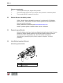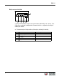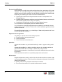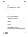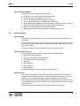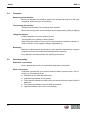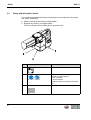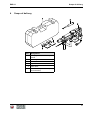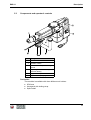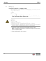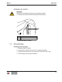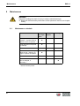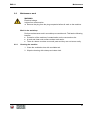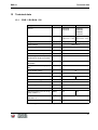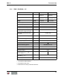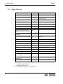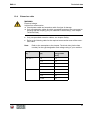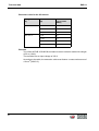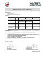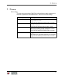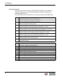
1
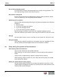
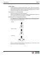
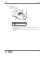
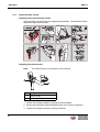
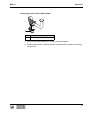
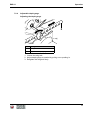
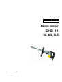
0212727en 004 12.2009 Electric hammer EHB 11 BL, BLM, BLS Operator's manual Manufacturer Wacker Neuson SE Preußenstraße 41 80809 München www.wackerneuson.com Tel.: +49-(0)89-354 02-0 Fax: +49-(0)89-354 02-390 Translation of the original operator’s manual in German Inhalt EHB 11 1 Foreword .................................................................................................................... 5 2 Úvod ........................................................................................................................... 6 2.1 2.2 2.3 2.4 3 Zobrazovací prostøedky tohoto návodu k obsluze......................................................... Wacker Neuson kontaktní partner.................................................................................. Popsané typy pøístrojù .................................................................................................. Identifikaèní znaèení pøístroje ....................................................................................... 6 7 7 7 Safety ......................................................................................................................... 9 3.1 3.2 3.3 3.4 3.5 3.6 3.7 3.8 3.9 Principle ......................................................................................................................... 9 Qualification of the operating personnel....................................................................... 12 Protective gear ............................................................................................................. 13 Transport...................................................................................................................... 14 Operating safety........................................................................................................... 14 Safety during the operation of hand machines............................................................. 16 Safety during the operation of electric appliances ....................................................... 17 Maintenance................................................................................................................. 18 Safety and information labels....................................................................................... 20 4 Scope of delivery .................................................................................................... 21 5 Description .............................................................................................................. 22 5.1 5.2 5.3 Application.................................................................................................................... 22 Functionality ................................................................................................................. 22 Components and operator's controls ........................................................................... 23 6 Transport ................................................................................................................. 26 7 Operation ................................................................................................................. 27 7.1 7.2 7.3 7.4 7.5 8 Prior to starting the machine ........................................................................................ Adjusting the machine.................................................................................................. 7.2.1 Operating mode .............................................................................................. 7.2.2 Speed/rpm....................................................................................................... 7.2.3 Supplementary handle .................................................................................... 7.2.4 Adjustable depth gauge .................................................................................. Changing tools ............................................................................................................. 7.3.1 General instructions ........................................................................................ 7.3.2 Tool holder SDS-max...................................................................................... 7.3.3 Tool holder for tool with hexagonal bolt .......................................................... 7.3.4 Tool holder for tool with spline shaft................................................................ Starting up.................................................................................................................... Decomissioning............................................................................................................ 27 28 28 29 30 33 34 34 34 36 37 38 39 Maintenance ............................................................................................................ 40 8.1 8.2 Maintenance schedule ................................................................................................. 40 Maintenance work ........................................................................................................ 41 3 EHB 11 8.2.1 8.2.2 8.2.3 Cleaning the machine ...................................................................................... 41 Lubricating the crank mechanism .................................................................... 42 Checking the tool holder for wear.................................................................... 43 9 Troubleshooting ...................................................................................................... 44 10 Disposal ................................................................................................................... 45 11 Accessories ............................................................................................................. 46 12 Technical data ......................................................................................................... 47 12.1 12.2 12.3 12.4 EHB 11 BL/BLM - 230 .................................................................................................. 47 EHB 11 BL/BLM - 115 .................................................................................................. 49 EHB 11 BLS - 115 ........................................................................................................ 50 Extension cable ............................................................................................................ 51 EC Declaration of Conformity ................................................................................ 53 UL Certificate ........................................................................................................... 55 13 4 Glossary ................................................................................................................... 57 1 Foreword 1 Foreword This operator's manual contains information and procedures for the safe operation and maintenance of your Wacker Neuson machine. In the interest of your own safety and to prevent accidents, you should carefully read through the safety information, familiarize yourself with it and observe it at all times. This operator's manual is not a manual for extensive maintenance and repair work. Such work should be carried out by Wacker Neuson service or authorized specialists. The safety of the operator was one of the most important aspects taken into consideration when this machine was designed. Nevertheless, improper use or incorrect maintenance can pose a risk. Please operate and maintain your Wacker Neuson machine in accordance with the instructions in this operator's manual. Your reward will be troublefree operation and a high degree of availability. Defective machine parts must be replaced immediately! Please contact your Wacker Neuson representative if you have any questions concerning operation or maintenance. All rights reserved, especially reproduction and distribution rights. Copyright 2009 Wacker Neuson SE No part of this publication may be reproduced in any form or by any means, electronic or mechanical, including photocopying, without the expressed written permission of Wacker Neuson. Any type of reproduction, distribution or storage on data media of any type and form not authorized by Wacker Neuson represents an infringement of copyright and will be prosecuted. We expressly reserve the right to make technical modifications – even without special notice – which aim at further improving our machines or their safety standards. 5 EHB 11 2 2.1 Úvod Zobrazovací prostředky tohoto návodu k obsluze Výstražné symboly Tento návod k obsluze obsahuje bezpečnostní předpisy těchto kategorií: NEBEZPEČÍ, VÝSTRAHA, OPATRNĚ, POZOR. Dodržujte tato upozornění. Vyloučíte tak nebezpečí smrti nebo úrazu obsluhy, vzniku hmotných škod nebo nesprávně provedené údržby. NEBEZPEČÍ Toto výstražné upozornění upozorňuje na bezprostředně hrozící nebezpečí, která vedou k těžkým úrazům nebo smrti. f Jednotlivá uvedená opatření vám umožní vyhnout se nebezpečí. VÝSTRAHA Toto výstražné upozornění upozorňuje na možná nebezpečí, která mohou způsobit těžká zranění nebo smrt. f Jednotlivá uvedená opatření vám umožní vyhnout se nebezpečí. OPATRNĚ Toto výstražné upozornění upozorňuje na možná nebezpečí, která mohou způsobit lehká zranění. f Jednotlivá uvedená opatření vám umožní vyhnout se nebezpečí. POZOR Toto výstražné upozornění upozorňuje na možná nebezpečí, která mohou způsobit hmotné škody. f Jednotlivá uvedená opatření vám umožní vyhnout se nebezpečí. Upozornění Upozornění: Zde obdržíte doplňující informace. 6 EHB 11 Pokyn pro manipulaci 2.2 f Tento symbol vás vyzve, abyste něco provedli. 1. Tento číslovaný symbol vás vyzve, abyste něco provedli v uvedeném pořadí. Tento symbol slouží k sestavení seznamu. Wacker Neuson kontaktní partner Vaším Wacker Neuson kontaktním partnerem je, podle země, Váš Wacker Neuson servis, Vaše Wacker Neuson dceřiná společnost nebo Váš Wacker Neuson obchodní zástupce. Adresy naleznete na internetu pod www.wackerneuson.com. Adresu výrobce najdete na začátku tohoto návodu k obsluze. 2.3 Popsané typy přístrojů Návod k obsluze slouží pro různé typy přístrojů jedné přístrojové řady. Z tohoto důvodu se některé obrázky můžou mírně lišit od vzezření vašeho přístroje. Kromě toho můžou být popsány díly, které váš přístroj neobsahuje. Jednotlivosti k popsaným typům přístrojů najdete v kapitole Technické parametry. 2.4 Identifikační značení přístroje Umístění typového štítku Poz. 1 Označení Typový štítek 7 EHB 11 Údaje na typovém štítku Typový štítek obsahuje údaje, které jednoznačně identifikují váš přístroj. Tyto údaje jsou nezbytné k objednávání náhradních dílů a v případě technických odborných dotazů. f Poznamenejte si údaje vašeho přístroje do následující tabulky: Poz. 8 Označení 1 Skupina a typ 2 Rok výroby 3 Č. stroje 4 Č. verze 5 Obj. č. Vaše údaje EHB 11 3 3.1 Safety Safety Principle State of the art This machine has been constructed with state-of-the-art technology according to the recognized rules of safety. Nevertheless, when used improperly, dangers to the life and limb of the operator or to third persons or damage to the machine or other materials cannot be excluded. Proper use The machine must only be used for the following purposes: Drilling holes with a diameter ranging from 12 to 125 mm. Breaking, chiseling, digging, puddling, hammering, ramming and deburring tasks. Processing natural and synthetic stone. Processing asphalt and any type of masonry and concrete. The machine may only be used with tools that are intended for use with the machine and the material being worked on. The machine may not be used for the following purposes: Working on hazardous materials such as asbestos. Its proper use also includes the observance of all instructions contained in this operator's manual as well as complying with the required service and maintenance instructions. Any other use is regarded as improper. Any damage resulting from improper use will void the warranty and the liability on behalf of the manufacturer. The operator assumes full responsibility. 9 Safety EHB 11 Structural modifications Never attempt to modify the machine without the written permission of the manufacturer. To do so will endanger your safety and the safety of other people! In addition, this will void the warranty and the liability on behalf of the manufacturer. Especially the following are cases of structural modifications: Opening the machine and the permanent removal of components from Wacker Neuson. Installing new components which are not from Wacker Neuson and not equivalent to the original parts in design and quality. Installation of accessories which are not from Wacker Neuson. It is no problem to install spare parts from Wacker Neuson. It is no problem to install accessories that are available in the Wacker Neuson product range of your machine. Please refer to the installation regulations in this operator's manual. Do not drill into the housing, e.g. to install signs. Water could penetrate the housing and damage the machine. Requirements for operation The ability to operate the machine safely requires: Proper transport, storage and setup. Careful operation. Careful service and maintenance. Operation Operate the machine only as intended and only when in proper working condition. Operate the machine in a safety-conscious manner with all safety devices attached and enabled. Do not modify or disable any safety devices. Before starting operation, check that all control and safety devices are functioning properly. Never operate the machine in a potentially explosive environment. Maintenance Regular maintenance work is required in order for the machine to operate properly and reliably over time. Failure to perform adequate maintenance reduces the safety of the machine. 10 Strictly observe the prescribed maintenance intervals. Do not use the machine if it requires maintenance or repairs. EHB 11 Safety Malfunctions If you detect a malfunction, you must shut down and secure the machine immediately. Eliminate the malfunctions that impair safety immediately! Have damaged or defective components replaced immediately! For further information, refer to chapter Troubleshooting. Spare parts, accessories Use only spare parts from Wacker Neuson or such that are equivalent to the original parts in design and quality. Only use accessories from Wacker Neuson. Non-compliance will exempt the manufacturer from all liability. Exclusion of liability Wacker Neuson will refuse to accept liability for injuries to persons or for damage to materials in the following cases: Structural modifications. Improper use. Failure to comply with this operator's manual. Improper handling. Using of spare parts which are not from Wacker Neuson and not equivalent to the original parts in design and quality. Using of accessories which are not from Wacker Neuson. Operator's manual Always keep the operator's manual near the machine or near the worksite for quick reference. If you have misplaced the operator's manual or require an additional copy, contact your Wacker Neuson representative or download the operator's manual from the Internet (www.wackerneuson.com). Always hand over this operator's manual to other operators or to the future owner of the machine. Country-specific regulations Observe the country-specific regulations, standards and guidelines in reference to accident prevention and environmental safety, for example those pertaining to hazardous materials and wearing protective gear. Complement the operator's manual with additional instructions taking into account the operational, regulatory, national or generally applicable safety guidelines. 11 Safety EHB 11 Operator's controls Always keep the operator's controls of the machine dry, clean and free of oil or grease. Operating elements such as ON/OFF switch, gas handles etc. may not be locked, manipulated or changed without authorization. Checking for signs of damage Inspect the machine when it is switched off for any signs of damage at least once per work shift. Do not operate the machine if there is visible damage or defects. Have any damage or defects eliminated immediately. 3.2 Qualification of the operating personnel Operator qualifications Only trained personnel are permitted to start and operate the machine. The following rules also apply: You are physically and mentally fit. You have received instruction on how to independently operate the machine. You have received instruction in the proper use of the machine. You are familiar with required safety devices. You are authorized to start machines and systems in accordance with the standards governing safety. Your company or the operator has assigned you to work independently with this machine. Incorrect operation Incorrect operation or misuse by untrained personnel can endanger the health and safety of the operator or third persons and also cause machine and material damage. Operating company responsibilities The operating company must make the operator's manual available to the operator and ensure that the operator has read and understood it. 12 EHB 11 Safety Work recommendations Please observe the recommendations below: 3.3 Work only if you are in a good physical condition. Work attentively, particularly as you finish. Do not operate the machine when you are tired. Carry out all work calmly, circumspectly and carefully. Never operate the machine under the influence of alcohol, drugs or medication. This can impair your vision, reactions and your judgment. Work in a manner that does not endanger others. Ensure that no persons or animals are within the danger zone. Protective gear Work clothing Clothing should be appropriate, i.e. should be close-fitting but not restrict your movement. When on construction sites, do not wear long hair loosely, loose clothing or jewelry including rings. These objects can easily get caught or be drawn in by moving machine parts. Only wear clothing made of material that is not easily flammable. Personal protective gear Wear personal protective gear to avoid injuries or health hazards: Non-skid, hard-toed shoes. Work gloves made of durable material. Overalls made of durable material. Hard hat. Ear protection. Face protection. Eye protection. Breathing protection in the case of dusty ambient air. Ear protection This machine generates noise that exceeds the country-specific permissible noise levels (individual rating level). It may therefore be necessary to wear ear protection. You can find the exact value in the chapter Technical Data. When wearing ear protection while working, you must pay attention and exercise caution because your hearing is limited, e.g. in case someone screams or a signal tone sounds. Wacker Neuson recommends that you always wear ear protection. 13 Safety 3.4 EHB 11 Transport Switching off the machine Before you transport the machine, switch it off and pull the plug out of the plug receptacle. Allow the motor to cool down. Transporting the machine Transport the machine in the carrying case supplied. Secure the carrying case on the transport device against tilting, falling or slipping. Lifting the machine A falling machine can cause serious injuries. The machine has no lifting or lashing points. When lifting the machine, secure it in a closed transport container or similar in order to prevent it from toppling, falling or slipping away. Restarting Machines, machine parts, accessories or tools that were detached for transport purposes must be re-mounted and fastened before restarting. Only operate in accordance with the operating instructions. 3.5 Operating safety Explosible environment Never operate the machine in a potentially explosive environment. Work environment Familiarize yourself with your work environment before you start work. This includes e.g. the following items: 14 Obstacles in the work and traffic area. Load-bearing capacity of the ground. The measures needed to cordon off the construction site from public traffic in particular. The measures needed to secure walls and ceilings. Options available in the event of an accident. EHB 11 Safety Safety in the work area When working with the machine especially pay attention to the following points: Electric lines or pipes in work area. Gas lines or water lines in the work area. Material becoming separated, dropping down or ejected. Make sure that you do not put other persons in danger. Pay maximum attention in the vicinity of drops or slopes. Risk of falling. Maintain a sufficient distance from flammable materials. Checks before starting work Check the following points before beginning work: Condition of tools. Machine settings. Connection value of the machine. Starting the machine Observe the safety information and warning notices located on the machine and in the operator's manual. Never attempt to start a machine that requires maintenance or repairs. Start the machine as described in the operator's manual. Vertical stability Always make sure that you stand firmly when working with the machine. This applies particularly when working on scaffoldings, ladders, uneven or slippery floors etc. Caution with hot parts Do not touch any hot parts such as tools, tool holders or guide cylinders during operation or directly afterwards. These parts can become very hot and can cause severe burns. Caution with movable parts Keep your hands, feet and loose clothing away from moving or rotating machine parts. Parts of your body being pulled in or crushed can cause serious injuries. Caution with toxic materials Some materials may contain toxic chemicals which are released during demolition. Therefore personal protective equipment must be worn to prevent inhalation of and skin contact with work dust. 15 Safety EHB 11 Do not direct towards people Do not direct the machine towards people in the vicinity during operation. The tool might be flung out and cause serious injuries. No persons endangered Be sure that no persons are endangered by flying or falling materials. Always work very attentively, and anticipate potential hazards. Switching off the machine Switch off the machine and pull the plug out of the plug receptacle in the following situations: Before breaks. If you are not using the machine. If you are changing the tool. If you are removing chips or splinters. Before storing the machine, wait until it has completely stopped running. Store the machine or put it down in such a way that it cannot tilt, fall down or slip. Storage Set the machine down or store it securely so that it cannot tilt, fall down or slip. Storage location After operation, allow the machine to cool and then store it in a sealed-off, clean and dry location protected against frost and inaccessible to children. 3.6 Safety during the operation of hand machines Safe working with hand machines Secure loose workpieces with suitable methods. While working, as a rule hold the machine on the provided handles with both hands. Always use the supplementary handles included with the machine. While working, hold the machine in such a way that hand injuries are avoided when hitting hard objects. Setting the hand machine down properly Set the machine down carefully. Do not drop the machine to the floor or from greater heights. Dropping the machine can cause injuries to other persons or the machine itself can be damaged. 16 EHB 11 Safety Safe working with the hammer Keep the tool holder closed during operation. Guide the power cable always from the machine to the rear and keep the power cable away from the working range of the machine. 3.7 Safety during the operation of electric appliances Specific regulations for electrical appliances Observe the safety information provided in the brochure General Safety Rules which is included in the scope of delivery of your machine. Also observe the country-specific regulations, standards and guidelines in reference to accident prevention in connection with electrical equipment and machines. WARNING Read all safety information and instructions. Failure to follow the safety information and instructions may result in electric shock, fire and/or serious injury. Save all safety information and instructions for future reference. Electric power supply for electrical appliances of class rating II Note: The rated voltage is indicated on the nameplate of your machine. The machine may only be connected to an electric power supply with all machine parts in proper working condition. Take special notice of the following components: Plug. Power cable over the entire length. Switch diaphragm of the ON/OFF switch, if there is one. Plug receptacles. Electrical appliances of class rating II have a strengthened or double insulation (protective insulation). They have no connection to the grounded conductor. There must be at least one of the following safety devices if connected to a stationary or mobile generator: Fault current protective switch. Isolation (earth leakage) monitor. IT-net. Note: Observe the respective national safety regulations! 17 Safety EHB 11 Extension cable The machine may only be operated with undamaged and tested extension cables! Only use extension cables with grounded conductor and correct connection of the grounded conductor to the plug and coupling (only for machines of class rating I, see chapter Technical data). Only use tested extension cables which are suitable for use at construction sites: Average rubber hose H05RN-F or better – Wacker Neuson recommends H07RN-F, an SOW cable, or a country-specific equivalent design. Immediately replace damaged extension cables (e.g. tears in the sheathing) or loose plugs and couplings. Cable drums and multiple plug receptacles must fulfill the same requirements as the extension cable. Protect extension cables, multiple plug receptacles, cable drums and connection couplings against rain, snow or any other forms of moisture. Uncoil the cable drum completely Danger of fire due to wound cable drum. Uncoil the cable drum completely before operation. Protecting the power cable Do not use the power cable to pull or lift the machine. Do not unplug the power cable by pulling on the cable. Protect the power cable from heat, oil and sharp edges. If the power cable is damaged or the plug is loose, have it replaced immediately by your Wacker Neuson representative. Protecting from moisture Protect the machine against rain, snow or any other forms of moisture. This could cause damage or other malfunctions. 3.8 Maintenance Maintenance work Service and maintenance work must only be carried out to the extent described in these operating instructions. All other procedures must be performed by your Wacker Neuson representative. For further information, refer to chapter Maintenance. 18 EHB 11 Safety Disconnecting the machine from the electric power supply Before carrying out service or maintenance work, pull the plug out of the plug receptacle in order to disconnect the machine from the electric power supply. Cleaning Always keep the machine clean and be sure to clean it each time you have finished using it. Do not use gasoline or solvents. Danger of explosion! Do not use high pressure washers. Permeating water can damage the machine. When electrical equipment is present, this can pose a serious injury risk from electric shocks. Cleaning the zerk fitting Wipe the zerk fitting with a clean cloth after the lubrication of the machine. There is a danger of electrocution if there is excessive grease on the zerk fitting. 19 Safety 3.9 EHB 11 Safety and information labels Your machine has adhesive labels containing the most important instructions and safety information. Make sure that all the labels are kept legible. Replace any missing or illegible labels. The item numbers for the labels are in the parts book. Item Label Description Guaranteed sound power level. 2 Wear personal protective gear to avoid injuries or health hazards: Ear protection. Eye protection. Read the operator's manual before startup. 0219174 1 3 20 US machines Warning. EHB 11 4 Scope of delivery Scope of delivery Item Designation 1 Carrying case with tool compartments 2 Grease gun 3 Rotary hammer 4 Operator's manual 5 Parts book General safety information (without illustration) 21 Description 5 EHB 11 Description 5.1 Application Use the machine only as intended, see chapter Safety, Proper use. A wide selection of easily interchangeable tools is available for drilling holes from 12 to 125 mm suitable for breaking, chiseling, digging, puddling, hammering, ramming and deburring. The machine is suited for processing natural as well as synthetic stone and asphalt and any type of masonry and concrete. 5.2 Functionality Principle The machine is a demolition hammer with a pneumatic percussion system as well as an additional drilling function. It is driven by a maintenance-free three-phase AC motor. A frequency converter converts the generated DC voltage to required threephase AC current. "Chiseling" operating mode The rotary movement of the three-phase AC motor is converted into a stroke movement via a transmission and a crank gear while in "Chiseling" operating mode. The piston is moved forwards and backwards by the crank gear, this compresses the air (forward movement) or generates a partial vacuum (backward movement). Due to change in pressure the percussion piston is moved forward and backwards (air cushion percussion system) and hits the tool. While in "Chiseling" operating mode, the drill drive is uncoupled via the safety clutch and the tool holder bushing is fixed in place to prevent turning in the tool holder. "Hammer drilling" operating mode While in "Hammer drilling" operating mode, the rotational movement of the motor is transferred to the drive shaft of the drill drive via a clutch. The drive shaft uses gear wheels to turn the tool holder bushing in the tool holder. 22 EHB 11 5.3 Description Components and operator's controls Item Designation 1 Tool holder 2 ON/OFF switch 3 Thumbwheel for pre-selecting speed 4 Adjusting lever for chiseling/ hammer drilling 5 Supplementary handle 6 Adjustable depth gauge Tool holder The machine is available with three different tool holders: SDS-max Hexagonal with locking strap Spline shaft 23 Description EHB 11 ON/OFF switch A start-up protection is linked with the ON/OFF switch. This start-up protection has the effect that the percussion rate or speed of the rotary hammer rises slowly after pressing the ON/OFF switch. The start-up protection prevents or reduces the chisel from slipping or the drill from jamming. Thumbwheel for pre-selecting speed Use the thumbwheel to pre-select the speed. Reducing the speed while in percussion operating mode diminishes the percussion forces as required for removing tiles, for example. Adjusting lever for chiseling/hammer drilling The adjusting lever for chiseling/hammer drilling has three positions as listed below. The arrow on the housing and the opposite symbol on the adjusting lever indicate the selected operating mode. Chiseling Hammer drilling Positioning While in operating mode "Positioning," it is possible to turn a flat chisel by hand to achieve the correct working position. 24 EHB 11 Description Supplementary handle Item Designation 1 Offset handle (not present on all machines) 2 Radial handle 3 Clamping wheel (not present on all machines) 4 Clamping piece The Pro-Ergo® supplementary handle can be adjusted to various positions to ensure safe working conditions and reduce operator fatigue. The offset and the radial handle are part of the supplementary handle. Adjustment options: The entire supplemental handle can be swiveled variably by 360°. The offset handle can be turned by approx. 270° in increments of 22.5° (not present on all machines). The radial handle can be screwed to the supplementary handle or housing sides. Adjustable depth gauge The depth gauge enables the variable adjustment of the drilling depth. 25 Transport 6 EHB 11 Transport WARNING Improper handling can result in injury or serious material damage. f Read and follow all safety instructions of this operator's manual, see chapter Safety. Transporting the machine The machine must be transported in the carrying case supplied. 1. Remove tool. 2. Turn the offset handle to the back (not present on all machines). 3. If mounted on housing, unscrew radial handle and screw onto supplementary handle. 4. Place the machine in the carrying case. 5. Wind up the power cable and place in the carrying case. Note: Do not kink the power cable! 6. Store the tools in the carrying case. 7. Place the carrying case on or into a suitable means of transport. 8. Secure the carrying case against falling over and down or sliding. 26 EHB 11 7 Operation Operation WARNING Improper handling can result in injury or serious material damage. f Read and follow all safety instructions of this operator's manual, see chapter Safety. 7.1 Prior to starting the machine After unpacking, the machine is ready for operation. Checking the machine f Check the machine and all components for damages. Checking the mains f Check if mains or power distribution on the construction site have the correct operating voltage (see nameplate of the machine or chapter Technical Data). f Check if mains or power distribution on the constructions site are protected in accordance with current standards and regulations. 27 Operation EHB 11 7.2 Adjusting the machine 7.2.1 Operating mode Selecting the operating mode WARNING Starting the machine during switching! Danger of injury with uncontrolled start up. f Actuate adjusting lever for chiseling/hammer drilling only after machine has come to a complete standstill. Item 1 Designation Adjusting lever for chiseling/ hammer drilling Check position of adjusting lever for chiseling/hammer drilling. Adjust the position of the chiseling/hammer drilling adjusting lever to meet the needs of the respective application: f Rotate the chiseling/hammer drilling adjusting lever a half a turn until lever locks into place. 28 EHB 11 7.2.2 Operation Speed/rpm Adjusting the speed Item 1 Designation Thumbwheel for pre-selecting speed Use the thumbwheel to adjust the speed: f Turn the thumbwheel for pre-selecting the speed counterclockwise (-) to reduce the speed. f Turn the thumbwheel for pre-selecting the speed clockwise (+) to increase the speed. 29 Operation 7.2.3 EHB 11 Supplementary handle Adjusting the supplementary handle Only operate the machine with the supplementary handle. The illustration below depicts the adjustment options. Adjusting the offset handle Note: The offset handle is not present for all machines. Item Designation 1 Offset handle 2 Clamping wheel 1. Loosen the clamping wheel by turning counterclockwise. 2. Swivel offset handle to desired position (take note of lock-in positions). 3. Tighten the clamping wheel by turning clockwise. 30 EHB 11 Operation Changing position of the radial handle Item 1 Designation Radial handle 1. Remove the radial handle by turning it counterclockwise. 2. Attach radial handle to desired position (supplementary handle or housing) using screw. 31 Operation EHB 11 Swiveling the supplementary handle Item Designation 1 Radial handle 2 Hexagonal bolt 3 Clamping piece 4 Allen wrench 1. Remove the radial handle by turning it counterclockwise. 2. Use the Allen wrench integrated into the radial handle to loosen the hexagonal bolt at the clamping piece. 3. Swivel supplementary handle to desired position. 4. Tighten the hexagonal bolt again. 5. Attach radial handle to desired position (supplementary handle or housing) using screw. 32 EHB 11 7.2.4 Operation Adjustable depth gauge Adjusting the depth gauge Item Designation 1 Wing bolt 2 Adjustable depth gauge 1. Loosen the wing bolt. 2. Adjust depth gauge as needed by pulling out or pushing in. 3. Retighten the wing bolt firmly. 33 Operation EHB 11 7.3 Changing tools 7.3.1 General instructions General notes You can change the tool without additional tools. Notes on using tools Only use tools with the following properties: 7.3.2 The tool must be suitable for the tool holder. The tool end must be undamaged. The tool must be sufficiently sharp to avoid impact damage. The tool must be suitable for the intended application. Tool holder SDS-max Inserting tool Item Designation 1 Tool 2 Tool holder 1. Clean tool end. 2. Insert tool into tool holder. 3. Turn tool and press into holder until automatically locked into place. 4. Check to see if the tool is locked by pulling on the tool. 34 EHB 11 Operation Removing tool Item Designation 1 Tool 2 Locking sleeve 1. Slide locking sleeve towards rear. The lock releases. 2. Remove tool from tool holder by pulling forward. 35 Operation 7.3.3 EHB 11 Tool holder for tool with hexagonal bolt Inserting tool Item Designation 1 Tool 2 Retaining spring 1. Clean tool end. 2. Swivel out retaining spring. 3. Push tool into the tool holder as far as it will go. 4. Return retaining spring to original position. 5. Check to see if the tool is locked by pulling on the tool. Removing tool 1. Swivel out retaining spring. 2. Remove tool from the tool holder. 3. Return retaining spring to original position. 36 EHB 11 7.3.4 Operation Tool holder for tool with spline shaft Inserting tool Item Designation 1 Tool 2 Lock bolt 1. Clean tool end. 2. Turn lock bolt by 90°. 3. Push tool into the tool holder as far as it will go. When inserting a chisel, make sure the notch on the tool points towards the spline shaft. 4. Turn lock bolt back by 90°. 5. Check to see if the tool is locked by pulling on the tool. Removing tool 1. Turn lock bolt by 90°. 2. Remove tool from the tool holder. 3. Return lock bolt to original position. 37 Operation 7.4 EHB 11 Starting up Connecting the machine to the power supply The machine may only be connected to AC single phase, connection values see chapter Technical Data. NOTICE Electrical voltage. Incorrect voltage can cause damage on the machine. f Check if the voltage of the current source corresponds with the information of the machine, see chapter Technical Data. WARNING Electrical voltage. Injuries from electrocution. f Check power cable and extension cable for signs of damage. f Only use extension cables for which grounded conductors are connected to the plug and the coupling (only for machines of class rating I). 1. If required, connect the machine to a permitted extension cable. Note: See chapter Technical data for the permitted lengths and cross-section areas of extension cables. 2. Insert the plug into the plug receptacle. 38 EHB 11 Operation Switching on the machine WARNING Injuries from insufficiently guided or uncontrolled machine. f Always hold machine with both hands and stand firmly. Item 1 Designation ON/OFF switch f Press the ON/OFF switch. 7.5 Decomissioning Switching off the machine 1. Release ON/OFF switch. 2. Wait until the machine has come to a complete standstill. 3. Set down the machine in such a way that it cannot tilt, fall or slip. 4. Pull the plug from the plug receptacle. 39 Maintenance 8 EHB 11 Maintenance WARNING Improper handling can result in injury or serious material damage. f Read and follow all safety instructions of this operator's manual, see chapter Safety. 8.1 Maintenance schedule Task Check power cable for perfect condition – if power cable is defective, have it replaced. * Visual inspection of all parts for damage. Clean the machine. Check shanks and cutting edges of tool – sharpen, reforge or replace as needed. Lubricate crank mechanism. Check tool holder for wear – have it changed, if necessary. * * 40 Daily before operation Every 20 hrs. Monthly Have these tasks carried out by the service department of your Wacker Neuson contact person. EHB 11 8.2 Maintenance Maintenance work WARNING Electrical voltage. Injuries from electrocution. f Remove the plug from the plug receptacle before all work on the machine. Work in the workshop Perform maintenance work in a workshop on a workbench. This has the following benefits: 8.2.1 Protection of the machine of contamination on the construction site. A level and clean work surface makes work easier. There is a better overview over small parts and they are not lost as easily. Cleaning the machine 1. Clean the ventilation slots with a suitable tool. 2. Wipe the housing with a damp and clean cloth. 41 Maintenance 8.2.2 EHB 11 Lubricating the crank mechanism Item 1 Designation Zerk fitting 1. Remove any dirt around the zerk fitting. 2. Place filled manual grease gun onto the zerk fitting and operate 10 to 12 times. Note: Only use special lubricants for lubricating, see chapter Technical Data. 3. Wipe the area around the zerk fitting with a clean cloth. 42 EHB 11 8.2.3 Maintenance Checking the tool holder for wear Item Value A 200 mm B Max. 6 mm 1. Insert the tool. Note: Use a new tool to measure only the wear of the tool holder and not the wear of the tool. 2. Measure the tool play 200 mm from insertion point. Play may not exceed 6 mm. If the play exceeds 6 mm, the tool holder must be replaced. 43 Troubleshooting 9 EHB 11 Troubleshooting Potential faults, their causes and remedies can be found in the following table. Malfunction Cause Remedy Machine not in operation For machines with 230 V: Input voltage too high (> 300 V) or too low (< 80 V). Provide correct voltage; if necessary use an extension cable with sufficient cross section. For machines with 115 V: Input voltage too high (> 150 V) or too low (< 45 V). Provide correct voltage; if necessary use an extension cable with sufficient cross section. Inverter has switched off due to excess temperature. Let machine cool off. Power cable interrupted. Check power cable, have it replaced if defective. * High grease resistance due to very low temperatures. Allow machine to warm up in warm environment (e.g. heated rooms). Seizing of moving parts (e.g. due to prolonged dry running). Have defective components replaced. * Too much borer dust in borehole. Pull drill bit out off borehole and remove dust from drill bit. Interfering reinforcing steel. Redrill borehole. Blocked percussion system Drill is stuck/jammed * 44 Have these tasks carried out by the service department of your Wacker Neuson contact person. EHB 11 Disposal 10 Disposal Dispose the machine and packaging through environmentally friendly recycling. During disposal observe the regional rules and regulations, e.g. the European Directive for obsolete electrical and electronic devices. Do not dispose of the machine in household rubbish. It must be disposed of separately. 45 Accessories EHB 11 11 Accessories There is a wide range of accessories available for the machine. For more information on the individual accessories, visit the following website: www.wackerneuson.com. 46 EHB 11 Technical data 12 Technical data 12.1 EHB 11 BL/BLM - 230 Designation Unit Item no. EHB 11 BL EHB 11 BLM 0008395 0610233 0008731 0008920 0008997 0610234 Length x Width x Height mm (in) 560 x 105 x 245 (22.0 x 4.1 x 9.7) 620 x 105 x 245 (24.4 x 4.1 x 9.7) Weight kg (lb) 11 (24.3) 11.7 (25.8) Rated voltage V 220-240 1~ Rated frequency Hz 50-60 Rated power consumption kW 1.38 Rated current consumption A 7.5 Minimum generator output requirement for single connection kW 3.3 Percussion rate electronically adjustable rpm 1,300-2,150 Drill speed electronically adjustable rpm 140-220 Single stroke energy J Breaking output (concrete C25) kg/h (lbs./h) Tool holder 19 600 (1,323) hex 19 x 82.5 Special lubricating grease Shell Retinax LX2 Drive Three-phase AC motor Class rating * II Protection class ** * SDS-max IP2X Sound pressure level LPA at operator's station *** dB(A) Total vibration value of the acceleration ahv **** m/s2 9.8 Uncertainty K m/s2 1,5 93 94 According to DIN EN 61140, description. 47 Technical data EHB 11 ** According to DIN EN 60529. *** According to ISO 11201. ****Determined according to DIN EN ISO 5349. 48 EHB 11 12.2 Technical data EHB 11 BL/BLM - 115 Designation Unit Item no. EHB 11 BL EHB 11 BLM 0008733 0008741 0008744 0008745 Length x Width x Height mm (in) 560 x 105 x 245 (22.0 x 4.1 x 9.7) 620 x 105 x 245 (24.4 x 4.1 x 9.7) Weight kg (lb) 11 (24.3) 11.7 (25.8) Rated voltage V 110-127 1~ Rated frequency Hz 50-60 Rated power consumption kW 1.2 Rated current consumption A 13 Minimum generator output requirement for single connection kW 3.3 Percussion rate electronically adjustable rpm 1,300-2,150 Drill speed electronically adjustable rpm 140-220 Single stroke energy J Breaking output (concrete C25) kg/h (lbs./h) Tool holder 19 600 (1,323) hex 19 x 82.5 Special lubricating grease Shell Retinax LX2 Drive Three-phase AC motor Class rating * II Protection class ** * SDS-max IP2X Sound pressure level LPA at operator's station *** dB(A) Total vibration value of the acceleration ahv **** m/s2 9.8 Uncertainty K m/s2 1,5 93 94 According to DIN EN 61140, description. ** According to DIN EN 60529. *** According to ISO 11201. ****Determined according to DIN EN ISO 5349. 49 Technical data 12.3 EHB 11 EHB 11 BLS - 115 Designation Unit Item no. * 0008742 Length x Width x Height mm (in) 620 x 105 x 245 (24.4 x 4.1 x 9.7) Weight kg (lb) 11.5 (25.4) Rated voltage V 110-127 1~ Rated frequency Hz 50-60 Rated power consumption kW 1.2 Rated current consumption A 13 Minimum generator output requirement for single connection kW 3.3 Percussion rate electronically adjustable rpm 1,300-2,150 Drill speed electronically adjustable rpm 140-220 Single stroke energy J 19 Breaking output (concrete C25) kg/h (lbs./h) 600 (1,323) Tool holder Large spline shaft size 19 Special lubricating grease Shell Retinax LX2 Drive Three-phase AC motor Class rating * II Protection class ** IP2X Sound pressure level LPA at operator's station *** dB(A) 93 Total vibration value of the acceleration ahv **** m/s2 9.8 Uncertainty K m/s2 1,5 According to DIN EN 61140, description. ** According to DIN EN 60529. *** According to ISO 11201. ****Determined according to DIN EN ISO 5349. 50 EHB 11 BLS EHB 11 12.4 Technical data Extension cable WARNING Electrical voltage. Injuries from electrocution. f Check power cable and extension cable for signs of damage. f Only use extension cables for which grounded conductors are connected to the plug and the coupling (only for machines of class rating I, see chapter Technical Data). Only use permitted extension cables, see chapter Safety. Refer to the following table for the required cross-section area of the extension cable: Note: Refer to the nameplate or the chapter Technical data (via the item number) for the type designation and voltage rating of your machine. Voltage [V] Extension [m] Cross-section area of cable [mm2] 110–127 1~ <8 1.5 < 13 2.5 < 20 4.0 < 30 6.0 < 27 1.5 < 44 2.5 < 70 4.0 < 105 6.0 220–240 1~ 51 Technical data EHB 11 Extension cable for the US market: Voltage [V] Extension [ft] Cross-section area of cable [AWG] 110–127 1~ < 36 14 < 58 12 < 89 10 < 75 16 < 121 14 < 190 12 < 302 10 220–240 1~ Example You utilize an EHB 11 BLM/230 and want to use an extension cable with a length of 50 m (164 ft). The machine has an input voltage of 230 V. According to the table, the extension cable must feature a cross-section area of 4.0 mm2 (AWG 12). 52 EC Declaration of Conformity Manufacturer Wacker Neuson SE Preußenstraße 41, 80809 München Product Type EHB 11 BL Product type EHB 11 BLM EHB 11 BLS Demolition/rotary hammer Item no. 0008395, 0610233, 0008733, 0008741 0008731, 0008920, 0008997, 0610234, 0008744, 0008745 0008742 Weight kg 11 11,7 11,5 Measured sound power level dB(A) 102 104 102 Guaranteed sound power level dB(A) 105 105 105 Conformity assessment procedure acc. to 2000/14/EC, Appendix VIII, 2005/88/EC at following test center: VDE Prüf- und Zertifizierungsinstitut, Merianstraße 28, 63069 Offenbach/Main Guidelines and standards This is to certify that this product meets and complies with the relevant regulations and requirements of the following guidelines and standards: 98/37/EC, from 29.12.2009: 2006/42/EC, 2006/95/EC, 2000/14/EC, 2005/88/EG, 2004/108/EC, EN 61000, EN 55014 Authorized person for technical documents: Axel Häret Munich, 19.08.2009 Franz Beierlein Head of product management Dr. Michael Fischer Head of Research and Development www.wackerneuson.com UL Certificate 13 Glossary 13 Glossary Class rating The class rating according to DIN EN 61140 specifies the safety measures for electrical equipment to avoid electrocution. There are four class ratings: Class rating Meaning 0 No special protection apart from the basic insulation. No grounded conductor. Plug connection without grounded conductor contact. I Connection of all conductive housing components to the grounded conductor. Plug connection with grounded conductor contact. II Reinforced or double insulation (protective insulation). No connection to the grounded conductor. Plug connection without grounded conductor contact. III Machines are operated on protective low voltage (< 50 V). Connection to the grounded conductor is not necessary. Plug connection without grounded conductor contact. 57 13 Glossary Protection class IP The protection class according to DIN EN 60529 indicates the suitability of electrical equipment for use in certain ambient conditions as well as the protection against risks. The protection class is specified by an IP code according to DIN EN 60529. Code Meaning 1st number: Protection against touching hazardous parts. Protection against permeating foreign objects. 0 Not protected against contact. Not protected against foreign bodies. 1 Protected against contact with the back of the hand. Protected against large foreign objects with diameter > 50 mm. 2 Protected against contact with one finger. Protected against medium-sized foreign objects (diameter > 12.5 mm). 3 Protected against touch with a tool (diameter > 2.5 mm). Protected against small foreign objects with (diameter > 2.5 mm). 4 Protected against touch with a wire (diameter > 1 mm). Protected against granular foreign objects (diameter > 1 mm). 5 Protected against contact. Protected against dust depositing inside. 6 Completely protected against any contact. Protected from dust. Code Meaning 2nd number: Protection against permeating water. 58 0 Not protected against permeating water. 1 Protected against water dropping vertically. 2 Protected against diagonally falling water (15° angle). 3 Protected against spray (60° angle). 4 Protected against spraying water from all directions. 5 Protected against water jets (nozzle) from any angle. 6 Protected against strong water jets (overflow). 7 Protected from temporary immersion in water. 8 Protected from ongoing immersion in water.