1
User's Guide
for Windows
Copyright 1999 by Microtek International, Inc.
All rights reserved.
Trademarks
Microtek, ScanMaker, and ScanWizard 5 are trademarks of Microtek International, Inc. IBM PC is the
trademark of International Business Machines Corporation. Windows and MS-DOS are trademarks of
Microsoft Corporation. Other product or company names are trademarks or registered trademarks of their
respective holders.
Important
Documents that you scan may be protected under copyright law. The unauthorized use of such documents
could be a violation of the rights of the copyright holder. Microtek bears no responsibility for the
unauthorized use of copyrighted materials.
To obtain optimal results from the Microtek scanning software and user's manual, you should be familiar with
such Windows concepts as pointing, clicking, dragging, and selecting from menus and dialog boxed. If these
things are new to you, refer to your Microsoft Windows User's Guide.
September 1999
Microtek Lab, Inc.
3715 Doolittle Drive
Redondo Beach, CA 90278-1226
Main: 310-297-5000
Sales: 800-654-4160
FAX: 310-297-5050
BBS: 310-297-5102
Technical Support: 310-297-5151
AutoTech fax back system: 310-297-5101
http://www.microtek.com
Microtek International, Inc.
6, Industry East Road 3
Science Based Industrial Park
Hsinchu, 30077, Taiwan
TEL: 886-3-5772155
FAX: 886-3-5772598
ii
Microtek Europe B.V.
Max Euwelaan 68
NL-3062 MA Rotterdam
The Netherlands
TEL: 31-10-2425688
FAX: 31-10-2425699
Contents
1.
Before You Begin
1-1
What is ScanWizard 5? .............................................................................................. 1-1
Standard & Advanced Control Panels ........................................................................ 1-2
Who Should Use the Standard Control Panel? ..................................................... 1-2
Who Should Use the Advanced Control Panel? ................................................... 1-2
Switching between Standard and Advanced Modes ............................................. 1-2
Scanner Control ................................................................................................. 1-3
Power-Saving .............................................................................................. 1-3
Compression Capability ............................................................................... 1-4
Scanner Information ........................................................................................... 1-5
ScanWizard 5 Help Features ...................................................................................... 1-6
On-Line-Help from ScanWizard 5-Standard Control Panel .................................. 1-6
On-Line-Help .............................................................................................. 1-6
Tutorial Guide ............................................................................................. 1-6
About ScanWizard 5 .................................................................................... 1-6
On-Line-Help from ScanWizard 5-Advanced Control Panel ................................. 1-7
About ......................................................................................................... 1-7
Installation ................................................................................................................ 1-7
Installing ScanWizard 5 ...................................................................................... 1-7
Installing Your Image Editor ............................................................................... 1-8
Installing Your E-mail/Web Browser .................................................................... 1-8
2.
Introduction to ScanWizard 5 Windows
2-1
ScanWizard 5-Standard Control Panel ....................................................................... 2-1
The ScanWizard 5-Standard Main Window ................................................................ 2-2
Instant Help for Beginners ......................................................................................... 2-2
On-Line-Help .................................................................................................... 2-3
Balloon Screen Tips ............................................................................................ 2-3
Tutorial, the Beginner's Guide ............................................................................. 2-3
ScanWizard 5-Advanced Control Panel ...................................................................... 2-4
3.
ScanWizard 5-Standard Control Panel Tutorial
3-1
About the Tutorial ..................................................................................................... 3-1
Using Windows ........................................................................................................ 3-1
iii
Windows Basics ................................................................................................. 3-1
Basic Mouse and Keyboard Techniques ........................................................ 3-2
Choosing and Selecting Items ...................................................................... 3-2
Launching ScanWizard 5-Standard Tutorial ............................................................... 3-3
Launching from an Image Application ................................................................ 3-3
Defining Image Source ................................................................................. 3-3
Launching ScanWizard 5-Standard from an Image Editor ............................. 3-4
Launching ScanWizard 5-Standard as Stand-Alone Program ................................ 3-4
Running from Start Menu ............................................................................ 3-5
Running from Scanner Located Start Buttons ............................................... 3-5
Running from ScanWizard 5 Assistant Buttons ............................................. 3-5
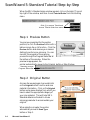
ScanWizard 5-Standard Tutorial Step-by-Step ............................................................ 3-6
Step 1 Preview Button ....................................................................................... 3-6
Step 2 Original Button ....................................................................................... 3-6
Step 3 Scan Type Button .................................................................................... 3-7
Step 4 Purpose Button ....................................................................................... 3-7
Step 5 Scale Output Button ............................................................................... 3-7
Step 6 Adjust Button ......................................................................................... 3-8
Step 7 Final Scanning Buttons ........................................................................... 3-8
“Scan” Button .............................................................................................. 3-9
“Scan to” Button .......................................................................................... 3-9
Reviewing the Scanning Sequence ........................................................................... 3-11
Quitting ScanWizard 5 ............................................................................................ 3-11
Conclusion ............................................................................................................. 3-12
4.
Your First Scan with ScanWizard 5-Standard
4-1
Launching/Exiting ScanWizard 5 ............................................................................... 4-1
When Launching from Scanner Start Buttons and Assistant Buttons .................... 4-1
Previewing Your Original Scan Material ...................................................................... 4-2
Create and Manipulate a Scan Frame Selection .................................................... 4-2
Plotting a Scan Frame Area from the Preview Image ...................................... 4-3
Re-sizing a Scan Frame ................................................................................ 4-3
Moving Scan Frame ..................................................................................... 4-3
Plotting a New Scan Frame .......................................................................... 4-4
Magnifying Your Preview Image .......................................................................... 4-4
Viewing Hidden Areas of Magnified Image ................................................... 4-4
Resizing Main Preview Window ................................................................... 4-5
Define Type of Output Image ..................................................................................... 4-6
iv
Resolution of Output Image ...................................................................................... 4-7
Intended Size of Output Image .................................................................................. 4-8
Improving Image Before Final Scan ............................................................................ 4-8
Output Image Setting Information ............................................................................. 4-9
Reset and Revert to Default Settings ........................................................................... 4-9
Final Scan and Output Image Destinations .............................................................. 4-10
ScanWizard 5-Standard Launched from an Application ..................................... 4-10
ScanWizard 5-Standard Launched as Stand-Alone Program ............................... 4-10
Storing Scanned Output Image to File ........................................................ 4-10
Routing the Saved Image to an Application ................................................ 4-12
Batch Saving of Outputs from ADF Equipped Scanners .............................. 4-12
Batch Routing of ADF Outputs to an Application ....................................... 4-12
Copy Output Image to Printer ................................................................... 4-13
Attach Output Image to an E-mail ............................................................. 4-14
Setting Preferences in ScanWizard 5-Standard .......................................................... 4-15
Preference Dialog Box ....................................................................................... 4-15
Appearance Dialog Box ..................................................................................... 4-16
Saving Your Favorite Color Scheme ............................................................ 4-17
5.
Your First Scan with ScanWizard 5-Advanced
5-1
Launching/Exiting ScanWizard 5-Advanced ............................................................... 5-1
Switching to Advanced Mode .................................................................................... 5-1
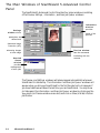
The Main Windows of ScanWizard 5-Advanced Control Panel ................................... 5-2
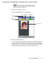
Operating ScanWizard 5-Advanced Control Panel ...................................................... 5-3
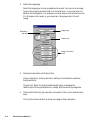
Scanning a single-bit image (line art or B&W diffusion) ............................................. 5-6
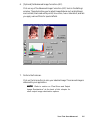
Scanning a grayscale image ........................................................................................ 5-8
Scanning an RGB color image .................................................................................. 5-11
Important scanning notes ........................................................................................ 5-14
For previews and scans ..................................................................................... 5-14
Using the Scan Frame tool ......................................................................... 5-14
Using the Prescan action button ................................................................. 5-15
Fixed Scan Frame ...................................................................................... 5-16
Fixed Output Size ..................................................................................... 5-16
Keep proportion ........................................................................................ 5-16
Selecting the correct resolution .................................................................. 5-16
For image correction ........................................................................................ 5-17
For scan job queue ........................................................................................... 5-19
Scaling the view of an image .................................................................................... 5-20
Option 1: Enlarging the view ..................................................................... 5-20
v
Option 2: Reducing the view ..................................................................... 5-21
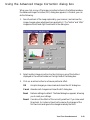
Correcting images ................................................................................................... 5-22
Using the Advanced Image Correction dialog box .................................................... 5-23
Final Scan and Output Image Destinations .............................................................. 5-24
ScanWizard 5-Advanced Launched from an Application ....................................5-24
ScanWizard 5-Advanced Launched as Stand-Alone Program ..............................5-24
Storing Scanned Output Image to File ........................................................ 5-24
Routing the Saved Image to an Application .......................................... 5-26
Batch Saving of Outputs from ADF Equipped Scanners ....................... 5-26
Batch Routing of ADF Outputs to an Application ................................ 5-26
Copy Output Image to Printer ................................................................... 5-27
Attach Output Image to an E-mail ............................................................. 5-28
6.
Reference to ScanWizard 5-Advanced
6-1
TWAIN Compliance .................................................................................................. 6-1
The Main Windows of ScanWizard 5-Advanced Control Panel ................................... 6-2
Running ScanWizard 5-Advanced Control Panel ........................................................ 6-3
Quitting ScanWizard 5-Advanced Control Panel ........................................................ 6-3
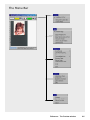
The Preview Window ................................................................................................ 6-4
The Menu Bar ........................................................................................................... 6-5
The Scanner Menu ............................................................................................. 6-6
Scanner Model ............................................................................................ 6-6
Get Current Scanner Info ............................................................................. 6-6
Scanner Probe ............................................................................................. 6-7
Exiting ScanWizard 5-Advanced Control Panel ................................................... 6-8
The View Menu .................................................................................................. 6-9
Overview Image .......................................................................................... 6-9
Prescan Image ........................................................................................... 6-10
Resize Window to Fit ................................................................................ 6-11
Show/Hide commands ............................................................................... 6-12
The Preferences Menu ...................................................................................... 6-13
Scan Material ............................................................................................. 6-14
The Scan Material Status icon .................................................................... 6-15
Color Matching Setup ................................................................................ 6-16
White/Black Points Setup .......................................................................... 6-19
Cursor Auxiliary Lines ............................................................................... 6-20
Overview Setup ......................................................................................... 6-22
Prescan Setup ............................................................................................ 6-23
vi
Monitor Gamma Setup .............................................................................. 6-24
Invert ........................................................................................................ 6-25
More command ......................................................................................... 6-26
The Help Menu ................................................................................................ 6-29
The Tool Buttons .............................................................................................. 6-31
Scan Frame tool ........................................................................................ 6-32
Magnify Glass tool ..................................................................................... 6-35
Pane tool ................................................................................................... 6-36
Color Picker tool ....................................................................................... 6-37
Action Buttons ................................................................................................. 6-39
Rulers .............................................................................................................. 6-40
Preview Area .................................................................................................... 6-41
The Settings Window .............................................................................................. 6-41
Output Image Parameters ................................................................................. 6-42
Type (Image Type or Scan Mode) ................................................................ 6-42
Resolution ................................................................................................. 6-44
Unit selection ............................................................................................ 6-45
Image Dimension controls ......................................................................... 6-46
Rotate and Flip tool ............................................................................ 6-47
How to use the Input-Output dimensions .................................................. 6-48
Scaling ............................................................................................... 6-48
Advanced Image Correction Tools ..................................................................... 6-49
Available Image Correction Effects .............................................................. 6-49
Introducing the Image Correction tools ...................................................... 6-50
Using the Advanced Image Correction dialog box ....................................... 6-50
The Action Buttons in the AIC dialog box ......................................................... 6-51
White/Black Points tool .................................................................................... 6-55
The White/Black Points dialog box (Color/Gray image) .............................. 6-55
The Threshold dialog box (Line-art image) ................................................. 6-57
Tone Curve tool ............................................................................................... 6-58
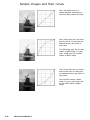
How to read the curve ............................................................................... 6-58
Sample images and their curves ................................................................. 6-60
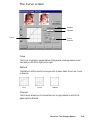
The Curve screen ...................................................................................... 6-61
Using the Curve buttons ............................................................................ 6-63
Using the Curve tool ................................................................................. 6-64
Brightness and Contrast tool ............................................................................. 6-65
Color Correction tool ....................................................................................... 6-67
vii
Using the Color Correction tool ................................................................. 6-68
Filters tool ....................................................................................................... 6-69
Blur filters ................................................................................................. 6-70
Sharpen filters ........................................................................................... 6-70
Edge Enhancement filter ............................................................................ 6-71
Emboss filter ............................................................................................. 6-71
Descreen .......................................................................................................... 6-72
The Information Window ........................................................................................ 6-73
Zoom Level Display .......................................................................................... 6-74
Cursor Locator ................................................................................................. 6-74
Output value .................................................................................................... 6-74
Sample size button ........................................................................................... 6-75
Using the Pixel Display ..................................................................................... 6-75
The Scan Job Queue Window .................................................................................. 6-76
Multiple Selections ........................................................................................... 6-77
How to read the Scan Job window .................................................................... 6-78
The New button ............................................................................................... 6-79
The Duplicate button ....................................................................................... 6-84
The Delete button ............................................................................................ 6-86
The Check button ............................................................................................ 6-86
The Save/Load button ...................................................................................... 6-87
The Up/Down Position Arrows ......................................................................... 6-89
Appendix
Appendix A: Configuring E-mail Software ................................................................. A-1
Appendix B: Using the Scanner Test Utility..................................................................B-1
Appendix C: Kodak Color Management System ........................................................C-1
Appendix D: Basic Concepts ...................................................................................... D-1
Appendix E: Troubleshooting ................................................................................... E-1
Appendix F: Glossary ................................................................................................F-1
viii
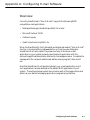
1
Before You Begin
What is ScanWizard 5?
ScanWizard 5 is scanning software that provides both amateur and professional
levels of color image reproduction and scan stage image editing for printed
material, 35mm color slides and filmstrips.
You can launch ScanWizard 5 from any TWAIN-compliant program or from
your image editing programs (e.g., Adobe Photoshop, Ulead PhotoImpact, etc.)
where scanned image is transferred to your image editor. You may further edit
the image in the image editing program if needed.
In addition to launching from your image editor, you can also run ScanWizard 5
as a stand-alone program. Under this stand-alone mode of operation, you can:
•
Send the scanned image to your printer
•
Open your e-mail processor and auto-attach the image file to your new
message
•
Open your web browser and view the scanned image or create HTML
documents
•
Open an image software program with the scanned image already
inserted and ready for use.
ScanWizard 5 consists of two programs bundled together, namely the
ScanWizard 5-Standard Control Panel (also known as “SW 5-Standard”
throughout this manual) and the ScanWizard 5-Advanced Control Panel
(also known as “SW 5-Advanced” throughout this manual). Either control
panel can be accessed easily and you can switch from one mode to another as
well (no need to exit one mode in order to start the other). The Standard mode
suggested for novice scanner users while the Advanced mode is designed for
experienced users. Both programs support most models of Microtek scanners.
Before You Begin
1-1
Standard & Advanced Control Panels
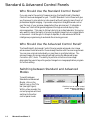
Who Should Use the Standard Control Panel?
If you are new to the world of image scanning, the ScanWizard 5-Standard
Control Panel was designed for you. The SW-Standard Control Panel will give
you the power to scan photos or documents without having to learn the art of
professional digital imaging. It provides a simple but straightforward control
over the look of your preview image before they are scanned. It integrates a
“follow-me” tutorial that guides beginners through an actual step-by-step
scanning session. This easy-to-follow tutorial is an instant educator for anyone
who wants to learn the basics of producing digital image from an original photo
or document. And though it is simple to operate, it uses advanced artificial
intelligence programming to automate the scanning process.
Who Should Use the Advanced Control Panel?
The ScanWizard 5-Advanced Control Panel provides advanced color image
enhancement tools tailored for those already familiar with the scanning process.
You can scan originals individually or scan them in multiple batches. The
scanned image can be reproduced optimally using the Advanced Image
Correction (AIC) tools. The ability to perform correction at scan stage
eliminates the need of exporting output image to an image application program
for further editing.
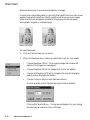
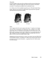
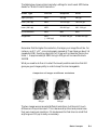
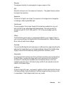
Switching between Standard and Advanced
Modes
To switch between
Standard and Advanced
Modes, click on the
Switch icon on the Title
bar (see right figure).
Within a few seconds, the
current program exits and
switches to the other
control panel mode.
1-2
Microtek ScanWizard 5
Click this icon to switch control
panels between Standard &
Advanced modes
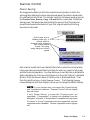
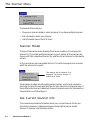
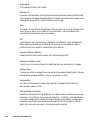
Scanner Control
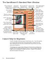
Power-Saving
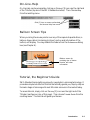
An energy saving feature is built into recent scanners models, in which the
scanning lamp switches to power-saving mode when the scanner remains idle
for a defined period of time. The scanner reverts to full power mode as soon as
the Preview, Scan, Scan to, Copy, or E-mail button is executed. Aside from
saving power, the feature also helps extend the service life of the lamp and
prevents caking and deformation of your film original resulting from long
exposure to lamp heat.
Click Scanner icon for
Standard mode (top), or
Scanner menu for
Advanced mode (bottom),
then choose Scanner
Control. The energy
saving dialog box will then
appear
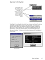
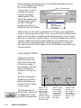
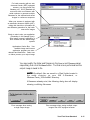
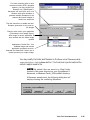
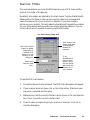
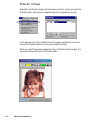
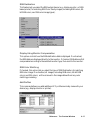
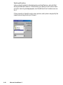
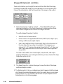
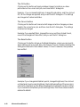
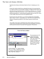
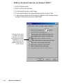
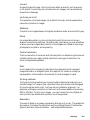
Each scanner model has its own default idle time to induce the scanning lamp
into power-saving mode and factory set time for warm-up, revert to full power,
and start scanning operation. You may define your own idle time or disable the
feature altogether by clicking on the Scanner icon from the Title bar in Standard
Mode or from the Scanner menu of the Menu bar in Advanced Mode. Then
from the resulting menu, choose Scanner Control. The following Scanner
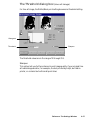
Control dialog box will then display to allow you to change the default settings.
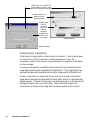
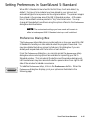
NOTE If your scanner does not support the 'Power-Saving'
and 'Compression' features, "Scanner Control" will not display
from the menu.
If only 'Power-Saving' is supported ('Compression' not
supported), "Compression" is grayed out (disabled) from the
dialog box. Likewise, if "Compression" is enabled, but only either
"Lossless" or "Lossy" compression mode is supported, only the
supported mode is enabled. The non-supported mode is grayed
out.
Before You Begin
1-3
Define idle time interval for
Power-Saving mode to take
effect (60 minutes maximum)
Uncheck this box to
disable PowerSaving feature
Compression
Pane is
enabled
only if the
scanner
supports
compression
feature (see
next page)
Standard Mode
Advanced Mode
Compression Capability
Compression is supported in certain models of scanners. If your scanner does
not support any of the compression modes (Lossless or Lossy), the
Compression pane in the Scanner Control dialog box is grayed out (see figure
in previous page).
If Lossless compression is available, the scanner will scan and compress the
image before sending the image data to ScanWizard 5. The image data is then
automatically decompressed without losing its image quality by ScanWizar 5.
If Lossy compression is supported, the scanner will scan and compress the
image before sending the image data to ScanWizard 5 where it is automatically
decompressed. The level of compression and decompression is dictated by the
setting provided in the Lossy slide meter. Take note that the higher the
compression, the lower is the image decompression quality, and vice versa.
1-4
Microtek ScanWizard 5
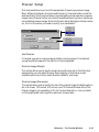
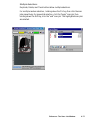
Scanner Information
Click Scanner menu
bar (Advanced mode,
top) or Scanner icon
(Standard mode,
bottom), then choose
scanner information
from their respective
menus to display the
Scanner Information
window
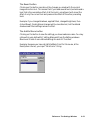
ScanWizard 5 is constantly in touch with your scanner, monitoring the scanner
availability, serviceability, as well as its make, and model. To see how your
scanner is doing, simply click the Scanner menu from the SW 5-Advanced
Menu bar, or click the scanner icon from the SW 5-Standard Title bar (see
figure above). From their respective menus, choose the item pertaining to
scanner information. The Scanner Information dialog box will then display as
shown below.
Standard Mode
Advance Mode
Before You Begin
1-5
ScanWizard 5 Help Features
On-Line-Help from ScanWizard 5-Standard
Control Panel
Aside from on-line-help, the Help [ ? ] icon on the Title bar also provides
access to Tutorial Guide program and SW 5-Standard version information.
Click Help [?] icon to access
on-line-help, Tutorial, and SW
5-Standard version information
On-Line-Help
To access on-line-help, click on the Help [?] icon. When the Help menu
displays, choose Help.
Tutorial Guide
SW 5-Standard has simple but effective tutorial that guides you through stepby- step scanning.
To access tutorial, simply click on the Help [?] icon near the right end of the
Title bar (see figure on top of this page), then choose Tutorial Guide from the
resulting menu. See Chapter 3 for more details on the tutorial.
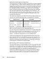
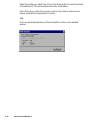
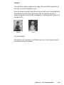
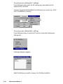
About ScanWizard 5
To learn more about the
version and release date of
your ScanWizard 5, click
on About from the menu
under the Help icon. The
following splash screen
will appear.
1-6
Microtek ScanWizard 5
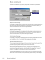
On-Line-Help from ScanWizard 5-Advanced
Control Panel
The on-line-help of SW 5-Advanced mode is
accessed through the Help menu on the Menu
bar.
The Help menu uses standard Windows
conventions for obtaining on-line help. If you are
not familiar with this procedure, refer to your
Microsoft Windows user's guide.
About
This command provides same the information as in the Standard mode and
displays the same splash screen shown in previous page.
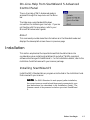
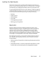
Installation
This section emphasizes the important areas that should be taken into
consideration when installing ScanWizard 5 and other TWAIN-compliant
software interfacing with ScanWizard 5. For full installation details, refer to the
Installation Guide that came with your scanner package.
Installing ScanWizard 5
Install the SW 5-Standard driver program as instructed in the Installation Guide
that comes with your scanner.
NOTE For SW 5-Standard to work properly after installation,
the correct scanner model should be properly connected to your
host beforehand (as described in the Installation Guide). The
Scanner needs to be powered on before you start ScanWizard
5.
Before You Begin
1-7
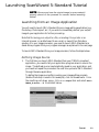
Installing Your Image Editor
If you intend to deliver your scanned image to an image editing program such as
Adobe Photoshop, you also need to install that particular image editing
program.
The table below lists the image editing programs supported by ScanWizard 5.
Supported Image Processors
Photoshop
PhotoDeluxe
PhotoImpact
Photo Express
Microsoft Imaging
ImageStar III
PageKeeper Standard MS Picture It
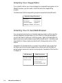
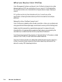
Installing Your E-mail/Web Browser
If you are going to send out your scanned image via e-mail or wish to view the
scanned image with a web browser (e.g., Microsoft IE or Netscape Navigator),
you will also need to install your Internet program. Refer to the table below for
web browser and e-mail programs supported by ScanWizard 5. Installation and
setup details for these programs are described in the Appendix section of this
manual.
Embedded in the ScanWizard 5 is a modest “Internet Mail” mail program that
will allow you to send scanned images via the Internet without the hassle of
going through commercial Internet e-mail programs. See details of this function
in Chapter 4.
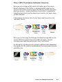
Web Browsers
E-Mail Processors
Netscape Navigator
Netscape Messenger 4.6
Internet Explorer
QualComm Eudora Pro 3.x
Outlook Express
Microsoft Outlook 97/98
1-8
Microtek ScanWizard 5
2
Introduction to
ScanWizard 5 Windows
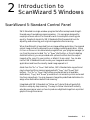
ScanWizard 5-Standard Control Panel
SW 5-Standard is a single-window program that offers a simple and straightforward way of navigating a scanning session. It is a program designed for
neophyte scanner users or for those who wish to accomplish scanning jobs
quickly. Despite its simplicity, SW 5-Standard offers the essential tools for
adjusting and enhancing your original image before final scanning.
When ScanWizard 5 is launched from an image editing application, the scanned
output image is directly delivered to your image processing application. When
it is run on its own or as a stand-alone program from your program manager (or
run from the scanner located “Go” or “Scan” start button, or from its desktop
Assistant buttons), you are provided with options to either store the output
image to a file, copy it to your printer, or attach it to an e-mail. You can also
instruct SW 5-Standard to auto-invoke your image and web browser
applications and have the recently saved image opened in it.
Aside from the “Go” or “Scan” start button, SW 5-Standard also supports and
may be launched from scanners equipped with “Copy” and “E-mail” start
buttons. The “Go” or “Scan” start button provides access to all available
destinations, “Copy” and “E-mail” provide short-cut access to printer and e-mail
functions respectively. You may however change the predefined destinations to
assign other destinations before final scanning.
Integrated with SW 5-Standard is a “follow-me” tutorial that will guide firsttimers on a step-by-step scanning. The easy-to-follow tutorial will instantly
educate new scanner users on how to produce a digitized image from a printed
graphic through the scanner.
Introduction
2-1
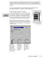
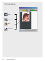
The ScanWizard 5-Standard Main Window
Click to perform final
scan and select a
destination for the
scanned image
Click to flip to
ScanWizard 5Advanced mode
Click for scanner info
and power-save &
compression control
Click for on-linehelp/SW 5 Standard info/tutorial
Click to select
output image type
(color, gray, or B&W)
Click to prescan
and preview
scan material
Click to define image
resolution to match
your target application
Zoom up (+) button to
magnify preview image
Click to select a size
(in aspect ratio) for
the output image
Preview image with the
scan selection
enclosed in a scan
frame
Click for image
enhancement tools
Click on Zoom Scale to
resize preview image
(magnify toward the top)
Status bar showing
summary settings for
output image. Click icon
for detailed info. The
status bar also serves
as a progress bar when
scanning is in process
Click to define category
of the original (scan
material)
Click to cancel your
defined choices and
revert to default
settings
Zoom down (-)
button to shrink
preview image
Click and hold Panning
Button to pan around a
magnified preview
image
Drag this corner
to resize
preview window
Click to access
"Preferences" dialog
box to set up scanning
functions and repaint
SW 5-Standard window
Instant Help for Beginners
The SW 5-Standard offers two types of instant help on line. One is through the
on-line-help system and the other is through the balloon-shape screen tips
which display hints on the function of each buttons as you hover your mouse
pointer over the buttons.
To help beginners, an easy to learn "follow-me" tutorial is also included in the
program that will instantly educated first timers on how to produce a digitized
image from a printed graphic through the scanner. Chapter 3 of this manual
discusses the details of the tutorial.
2-2
Microtek ScanWizard 5
On-Line-Help
On-line-help can be accessed by clicking on the Help [?] icon near the right end
of the Title bar (top bar of the SW 5-Standard window). Then Choose Help
from the resulting menu.
Click [?] icon to access on-line-help
and choose Help from menu
Balloon Screen Tips
When you bring the mouse pointer over any of the capsule shaped buttons, a
balloon-shape callout (containing hints on function and information of the
button) will display. You may disable this feature from the Preferences dialog
box (see Chapter 4).
Balloon screen tip
providing tips on button
function and other
information
Tutorial, the Beginner's Guide
SW 5-Standard has something unique for neophytes in scanning technology. It
provides a simple but effective Tutorial that actually guides you, step-by-step on
the basic stages of scanning with most Microtek scanners in the market today.
To access tutorial, simply click on the Help [?] icon near the right end of the
Title bar (see figure on top of this page). Then choose Tutorial Guide from the
resulting menu. The tutorial will guide you thereon.
Introduction
2-3
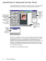
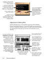
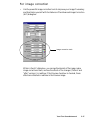
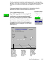
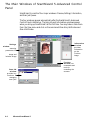
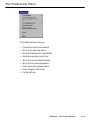
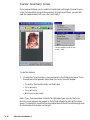
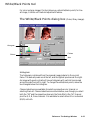
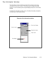
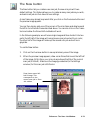
ScanWizard 5-Advanced Control Panel
The ScanWizard 5-Advanced Control Panel has four major windows consisting
of the Preview, Settings , Information , and Scan Job Queue windows.
Information
window
provides
sampling of
pixels of the
prescan
images
Settings window
where output
image parameters
are defined and
includes the
Advanced Image
Correction (AIC)
tools for
enhancing images
at scan stage
Preview window
has the commands
and tools for
interfacing with the
scanner
Scan Job
Queue
window
provides
management
of scan jobs
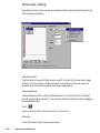
The Preview and Settings windows will always appear automatically whenever
ScanWizard 5 is started up. The Information and Scan Job Queue windows
will appear when you bring up ScanWizard for the first time but will not
reappear if you have hide these windows the last time you ran ScanWizard. You
may show (or hide again) the Information and Scan Job Queue window by
clicking on the View menu (on Preview window menu bar) and click on Show
(or Hide) Info/Scan Job Window.
See Chapter 5 for more detailed information.
2-4
Microtek ScanWizard 5
3
ScanWizard 5-Standard
Control Panel Tutorial
About the Tutorial
This tutorial is embedded in the ScanWizard 5 driver program. To access the
tutorial, you need run to ScanWizard 5-Standard. A powered-up scanner
should also be connected and configured with your host computer (refer to the
Installation Guide) before running the SW 5-Standard. You also need to place a
scan material (original image) on your scanner to obtain a scanned output image
at the end of the tutorial.
The tutorial is intended as a hands-on guide for those with no previous
background on scanning graphic images. In fact beginners can easily produce
an output by running the tutorial and let it do the almost hand-free scanning for
him.
Using Windows
The tutorial assumes that you are familiar with Windows operation. Some
Windows basics are explained below, but if you are unfamiliar with such things
as using a mouse, choosing a command from a menu, opening multiple
windows, entering text, selecting options, choosing actions, or sizing windows,
you should run the Windows tutorial before proceeding. The Windows tutorial
is on the Help menu of the Program Manager window.
Windows Basics
This section highlights some of the basic skills you need in order to work with
the SW 5-Standard window. If you are already familiar with Windows, skip to
the section on Launching SW 5-Standard Tutorial (page 3-3).
Tutorial
3-1
Basic Mouse and Keyboard Techniques
This following explains some of the basic terms that are used in this manual.
Term
Meaning
Click
To quickly press and release mouse left button
Double-click
To click mouse left button twice in rapid succession
Drag
To hold down mouse left button while you move the mouse
Click
To click mouse left button twice in rapid succession
Choosing and Selecting Items
In any Windows application, the terms choose and select have different, and
specific, meanings. Selecting an item usually means marking it with the
selection cursor, which can appear as a highlight, a dotted rectangle, or both.
You also select check boxes in dialog boxes. Selecting alone does not initiate an
action.
NOTE A dialog box is a window that appears temporarily to
request information. Many dialog boxes have options you must
select before SW 5-Standard can carry out a command.
One way to select an item is to point at it and click.
You choose an item to carry out an action. For example, choosing an icon
might start an application, open a window, or carry out a command. You can
also choose an item from a menu, or choose a command button in a dialog box.
One way to choose an item is to point at it and double-click.
Menus and dialog boxes are discussed in great detail in the Microsoft Windows
User’s Guide.
3-2
Microtek ScanWizard 5
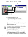
Launching ScanWizard 5-Standard Tutorial
NOTE Be sure you have the original image (or scan material)
properly placed on the powered on scanner before launching
tutorial.
Launching from an Image Application
You will need to launch SW 5-Standard from an image editing application (e.g.,
Photoshop, PhotoImpact, etc.) if you wish to immediately deliver your output
image to your application for further processing.
Note that for saving your output to a file, or sending it to a printer or an
Internet browser, or as attachment to an e-mail, or saved it to a file before
sending it to your image processor; you need to launch SW 5-Standard as a
stand-alone program from your program manager as explained in the next page.
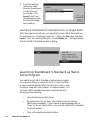
To launch SW 5-Standard from your image processor, follow the steps below:
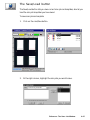
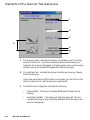
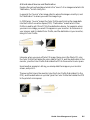
Defining Image Source
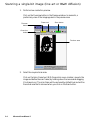
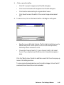
1.
The first time you launch SW 5-Standard from your TWAIN-compliant
application, you need to tell your application program where to source the
image. The defined source is automatically saved in your application, and
you need not repeat the procedure the next time you enter SW 5-Standard
through the same application.
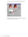
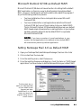
To define the image source after invoking your image editing program
(Adobe Photoshop is used in this example), click on the File menu. From
the resulting pull-down menu, click on the Import item and select Select
TWAIN_32 Source... as illustrated below.
Tutorial
3-3
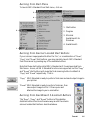
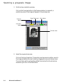
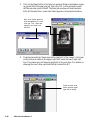
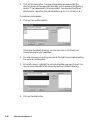
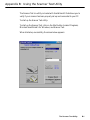
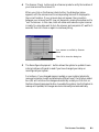
2.
From the resulting
dialog box, select
Microtek ScanWizard
5 as the source of
your image. Click
Select to exit from
the dialog box and to
auto-save the image
source setting.
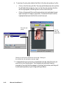
Launching ScanWizard 5-Standard from an Image Editor
With the image source defined, you may directly invoke SW 5-Standard from
the application (i.e., Photoshop) menu bar. Click on the File menu and select
Import. From the resulting dialog box, choose TWAIN_32 ... (see figure below).
Wait for the SW 5-Standard window to display.
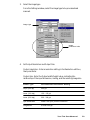
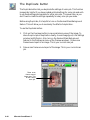
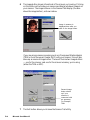
Launching ScanWizard 5-Standard as StandAlone Program
You need to launch SW 5-Standard as a stand-alone program
if you want to save your output into a file, or have it printed,
or save it and immediately attach the file to an e-mail, or view
the output image with your browser, or image processor. You
can launch SW 5-Standard as an stand-alone operation by
doing one of the following:
3-4
•
Launching from your Start menu.
•
By pressing the “Go” or “Scan” start button from your scanner
(whichever is available). If your scanner is also equipped with the
“Copy” or “E-mail” start buttons, you may also launch SW 5-Standard
from such buttons.
•
Click on the desktop Assistant buttons.
Microtek ScanWizard 5
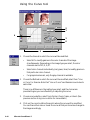
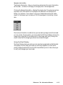
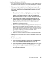
Running from Start Menu
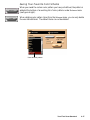
To launch SW 5-Standard from Start menu, click on3
4
1. Start button
2
2. Program
3. Microtek
ScanWizard 5 for
Windows
4. ScanWizard 5
1
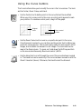
Running from Scanner Located Start Buttons
If your scanner is equipped with either the "Go", or a combination of "Scan",
"Copy", and "E-mail" start buttons, you may remotely launch SW 5-Standard
from the scanner by pressing any of the available buttons.
Note that these start buttons start SW 5-Standard as if it were launched from
Start menu. Hence, all SW 5-Standard functions are supported, but the “Copy”
and “E-mail” start buttons will cause the final scanning button to default at
“Copy” and “E-mail” respectively. That is “Copy” SW 5 Standard is ready to perform final scan and send output image to
your printer.
“E-mail” SW 5 Standard is ready to perform final scan, then
save output image to a file. It then opens and
attaches the image to your e-mail editor.
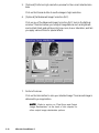
Running from ScanWizard 5 Assistant Buttons
The "Scan", "Copy", and "E-mail" buttons of the desktop
Assistant buttons functions the same way as with the remote
scanner located start buttons described above.
Tutorial
3-5
ScanWizard 5-Standard Tutorial Step-by-Step
When the SW 5-Standard main window appears, click on the help [?] icon at
top right of the window, and then choose Tutorial Guide from the resulting
menu.
Click (?) to access Tutorial and
choose Tutorial Guide from menu
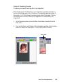
Step 1 Preview Button
You are now prompted (by the pointer
position) to click the Preview button with a
balloon screen tip on its function. Click the
Preview button and observe your scanner
starting to perform pre-scanning. You can
monitor the progress of the scanning
process through the Progress Status Bar at
the bottom of the window. When the
preview image appears, the
pointer automatically moves to the Original button or Step 2 below.
Scanning process
Progress Status Bar
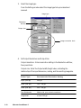
Step 2 Original Button
A screen tip appears again to provide hints
on the Original button function and scan
material information. Click on the Original
button and a menu displays from which you
have to select the appropriate category of
your scan material. This will help SW 5Standard determine the best in-house
scanning parameter to accommodate your
original.
When selection is made, the pointer
automatically moves to Scan Type
button or Step 3.
3-6
Microtek ScanWizard 5
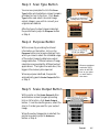
Step 3 Scan Type Button
You are now prompted to click the Scan
Type button while a balloon screen tip again
provides hint on its function. Click Scan
Type button and select into what image
output category you wish to convert your
original scan material.
After the type of output image is selected,
the pointer auto jumps to Purpose button
or Step 4.
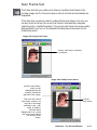
Step 4 Purpose Button
With a screen tip providing functional
information on the button, click on the
Purpose button and a menu displays from
which you have to select the intended usage
of the output image to determine output
image resolution. Different values of image
resolution are provided for different output
applications. The higher the resolution, the
bigger is the memory size required.
When a purpose is defined, the pointer
automatically goes to Scale Output button
or Step 5.
Observe pertinent
resolution (DPI)
value in the Edit
box as you point
on each item in
the menu
Step 5 Scale Output Button
With pointer on the Scale Output button
and a balloon screen tip again providing
hint on its function, click Scale Output
button. From the resulting menu, select the
size (in % scale) you want for your output
image.
When the output image size is selected, the
pointer now auto jumps to Advance
button or Step 6.
Tutorial
3-7
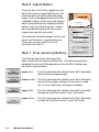
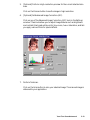
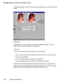
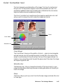
Step 6 Adjust Button
The screen tip on this button suggests you may
adjust (color toning, image brightness, etc.) the
preview image to provide an enhanced output
image. Click on the Adjust button and the SW
5-Standard image correction tool panel displays.
Adjust image appearance by dragging the pellet
button of each tool along its grooves. Observe
the live update taking place with the preview
image as you reposition each pellet.
Click anywhere outside the image correction tool
panel to exit the panel, or press the Enter key.
The pointer then auto points to the final
scanning button (Step 7).
Step 7 Final Scanning Buttons
This is the last step of your scanning tutorial
session where the final scanning is performed. The final scanning button
designated function will differ depending on how the SW 5-Standard was
launched as explained below.
3-8
Scan button
This is the resulting button (default) when SW 5-Standard is
launched from an image processor.
Scan to button
This is the resulting button (default) when SW 5-Standard is
launched from program manager or from scanner located
“Go” or “Scan” start button, whichever is available.
Copy button
This is the resulting button (default) when SW 5-Standard is
remotely launched from scanner “Copy” start button.
E-mail button
This is the resulting button (default) when SW 5-Standard is
remotely launched from scanner “E-mail” start button.
Microtek ScanWizard 5
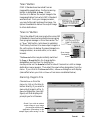
"Scan" Button
If SW 5-Standard was launched from an
image editing application, the final scanning
button is designated as Scan. Its sole
function is to deliver the output image to the
image application from which SW 5-Standard
was launched. From your image processor,
you may further edit and save the image. No
option is available to deliver the output image
to other destinations.
"Scan to" Button
This is the default final scanning button when SW
5-Standard is launched as a stand-alone program
from program manager or from the scanner “Go”
or “Scan” start button, (whichever is available).
The Primary function is to save output image to a
file, with options to deliver the saved image to an
image processor, an e-mail editor, or to a web
browser.
Scan Image
Destination
menu
The Scan to button may be instantly switched
to Copy or E-mail button (to change button
designation and function ) by holding the
mouse pointer on the Scan to button for about 2 seconds or until an image
destination menu appears. Then select the new button designation from the
menu. If you click on the Scan to button, a Save as dialog box will display
(same effect when you click on Scan to from menu as detailed below).
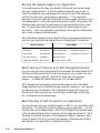
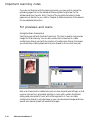
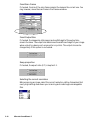
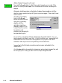
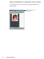
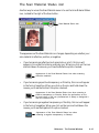
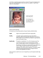
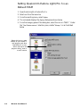
Scanning Image to File
Choose Scan to from the
menu (or click on the Scan to
button directly) if you want to
save output image to a file. A
Save As dialog box (see right
figure) will then display and
prompts you for a filename.
Check if you wish to redirect
output image to your image
processor/e-mail/browser
application (Photoshop in this
sample figure) after saving it to file
Tutorial
3-9
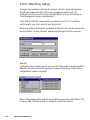
Enter a filename on the 'Filename' pane if the default filename does not suit
you. Click the Save button to store
the scanned output image
Enter a filename here
into your disk. If you do
not assign a preferred
directory, the image is
saved by default in the
'Data' folder located under
the same directory where
your SW 5-Standard
program is located, or in
Windows\ Twain_32\ScanWiz5.
At this juncture, if you wish to redirect the output image to your image editor,
e-mail, or web browser after saving it to file, you can do so by simply ticking the
check box for this feature and selecting the target application you wish to work
with from the combo box (see above figure). Clicking the Save button with the
checkbox enabled, will save the output image into a file, followed by an autoexecution of your selected application. When the application is invoked, it
auto-opens the recently saved image from file. More details are provided in the
following sections.
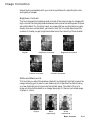
Copy Image to Printer
Choose Copy from the
destination menu if you
wish to print a hard copy
of the output image. A
Print dialog box (see right
figure) will display to
prompt you for the print
setup.
Note that the dialog box
provides a print position
setup to facilitate proper
placement of your image
in a print page.
Click the Ok button to
start printing. Notice that
the Scan to button now
becomes the Copy button.
3-10
Microtek ScanWizard 5
Select "Fit to
Page" to print
and fill whole
page (image is
enlarged and
printed full page,
but may not print
proportionally)
Select "Center
Horizontally"
to print image
at the center
of right and
left edges of
the page
Select "Center
Vertically" to
print image at
the center of
top and bottom
edges of the
page
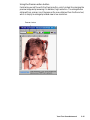
Attach to E-mail
Choose E-mail from the
menu if you wish to send
out a copy of the output
image as attachment to an
e-mail. Notice that the
Scan to button now
becomes the E-mail
button. When the Save
As dialog box appears
(with application check
box enabled by default),
click the Save button.
Watch the final scan being
performed and the
resulting output image is saved to file. Then your e-mail editor (Netscape
Messenger, Microsoft Outlook, etc.) is automatically launched with the saved
output file already attached to it.
If you have not installed any e-mail editor, Internet Mail (the Microtek provided
e-mail processor embedded in the SW 5-Standard) will default and provide you
with the facility to send the output image by e-mail.
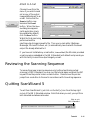
Reviewing the Scanning Sequence
To review the proper scanning sequence only (without performing actual
scanning) of SW 5-Standard, you may run the tutorial again and press the ESC
key each time the pointer hovers on each button. Observe how the pointer
jumps from one button to the next in accordance with its working sequence.
Quitting ScanWizard 5
To exit from ScanWizard 5, just click on the Exit [X] icon from the top right
corner of the SW 5-Standard window. Note that when you exit, you quit from
both standard and advanced modes.
Click to quit
SW 5-Standard
Tutorial
3-11
Conclusion
This ends your tutorial session. You may now go through it again to gain a
deeper understanding of SW 5-Standard scanning steps and its basic features.
Once you master the tutorial, go to Chapter 4 for an actual scanning session and
for more details on SW 5-Standard not covered in this chapter.
3-12
Microtek ScanWizard 5
4
Your First Scan with
ScanWizard 5-Standard
Launching/Exiting ScanWizard 5
Launch ScanWizard 5 as described in the preceding chapter (see page 3-3). Be
sure to launch from your image processor if you wish to further edit or
manipulate the scanned image with your application. Launch from your
scanner start buttons, ScanWizard 5 Assistant button, or Start menu if you are
going to save, print, browse, or e-mail the output image.
To quit ScanWizard 5, simply click on the [X] button at top right corner of the
SW 5-Standard window.
When Launching from Scanner Start Buttons and
Assistant Buttons
If your scanner is equipped with the “Go”, or the combination of “Scan”,
“Copy”, and “E-mail” start buttons, you may launch SW 5-Standard by pressing
any of the buttons (or clicking from the desktop Assistant buttons). SW 5Standard will run as a stand-alone program, but varying default output image
destinations will result in each type of button:
“Go”/“Scan” start button runs SW 5-Standard as if it were launched from Start
menu. The last function defined for the scan button will default
for the next scanning session. You may change output image
destination as you please.
“Copy”
start button runs SW 5-Standard with the primary purpose of
printing your output image. Hence, you are prompted with a
printer setup dialog box before final scanning. You may however
abort printing and redirect output image to other destination as in
regular operation.
“E-mail”
start button runs SW 5-Standard with the intent of attaching the
output image to your e-mail composer. Hence, you are prompted
with a dialog box where “E-mail” or “Internet Mail” are the only
possible destinations for the output image after it is saved to file.
You may however abort the e-mail processing and redirect output
image to other destination.
Your First Scan-Standard
4-1
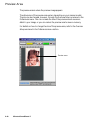
Previewing Your Original Scan Material
By default, SW 5-Standard automatically detects and creates a preview image of
your original in the SW 5-Standard preview window when you first launched
the program.
If you have disabled the auto preview function in the Preferences dialog box
(see section on Setting Preference in SW 5-Standard in this chapter), you need to
manually click the Preview button to prescan and preview your original scan
material into the SW 5-Standard window.
If you have disabled the auto detect function as well,
SW 5-Standard will prescan your original as you have
defined in the previous scan session. If the resulting
type of the preview image does not match with your
original, you need to tell SW 5-Standard the actual
type of your original by clicking on the Original
button. From the resulting menu (see figure at right),
select the nearest scan material category that matches
your original.
NOTE There is no order of sequence required for using the
image setup buttons in defining various aspects of your image,
i.e., Original, Scan Type, Purpose, Scale Output, and Adjust
buttons.
Create and Manipulate a Scan Frame Selection
If you wish to scan only a segment of your scan material, you can do so by
plotting a scan frame (or a scan job selection) around the chosen area within the
preview image. The area outside the scan frame is excluded from the final
scanned output image.
4-2
Microtek ScanWizard 5
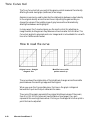
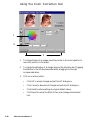
Plotting a Scan Frame Area from the Preview Image
To plot a scan frame, point at any corner of
your intended scan frame. When the crosshair
pointer appears, drag diagonally until you have
the desired image selection enclosed in a frame,
then release the mouse. Your actual scan frame
border now turns into cascading lines.
5
Crosshair pointer
Scan Frame
Re-sizing a Scan Frame
Ö
You may adjust the size of your scan frame by
pointing at any side of the scan frame. When
the 2-way arrow pointer appears, drag
horizontally or vertically until you have
achieved the desired adjustment of the width
and height of the scan frame.
Ö
You can also adjust the scan frame width and
length together by pointing at any corner of the
scan frame. When the diagonal 2-way arrow
pointer appears, drag diagonally until you
achieve the desired adjustment to the scan
frame.
Ö
2-way arrow pointers
Ö
Moving Scan Frame
E
When you wish to maintain or use the existing
scan frame size to select another scan image
selection within the same preview image, just
move the existing scan frame over to the new
scan job area. To accomplish this, point
anywhere within the existing scan frame.
When the 4-way arrow pointer appears, drag
the scan frame to the location of the new
selected image area.
4-way arrow pointer
Your First Scan-Standard
4-3
Plotting a New Scan Frame
You can always create another scan frame over
an existing one or at another location of the
same preview image. Like your previous scan
frame, point at any corner of your intended
new selection. When the crosshair pointer
appears, drag diagonally until you have the new
desired image selection enclosed in a frame.
When you release the mouse button, the
previous scan frame is discarded.
Previous selection or
existing scan frame
Drag crosshair pointer
to plot a new scan
frame selection.
(Previous selection is
discarded.)
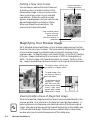
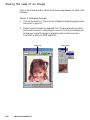
Magnifying Your Preview Image
SW 5-Standard allows magnification of your preview image to as much as four
times (4x) the size of your original. The zoom scale bar (located at the right side
of your preview image) is provided to easily accomplish zooming of your
preview image. To magnify image, click toward the top (or the plus [+] button)
of the bar, image is zoomed up to an increment of 100% to the maximum of
400%. To shrink image, click toward the bottom (or minus [-] button) of the
bar, image is zoomed down at same increment, to its original size as minimum.
To magnify image, click on plus
(+) button or on higher scales
To shrink image, click
on minus (+) button or
on lower scales
To view hidden area of
magnified
image,
click Pane tool (left).
When panning frame
occurs, drag pane
pointer (right) toward
hidden area of image
Viewing Hidden Areas of Magnified Image
When the magnified image becomes too large to be accommodated within the
preview window, click and hold on the Pane tool (see right figure above). A
panning frame occurs displaying a miniaturized replica of the whole original
image. Start panning the pane pointer toward the direction of the hidden area
in the miniaturized image. Observe the live or realtime effect in the preview
window which synchronizes the exposures of the hidden area .
4-4
Microtek ScanWizard 5
Resizing Main Preview Window
Ö
Another option to view the hidden
area of a zoomed up image is to
directly expand the size of the
preview window. Simply point at the
bottom-right corner of the window.
When the diagonal 2-way arrow
pointer occurs, drag the corner down
diagonally to expand the window.
If you have a small-size original (e.g.,
pocket book photo, match box, slide,
etc.), expanding the preview window
before clicking the Preview button
will allow you to view a larger size
and a clearer preview of your
original. This will make selection of
a scan frame from the preview image
easier.
Point at this corner. Then drag the 2way arrow pointer downward diagonally
to expand preview window and expose
hidden area of magnified image
Image on preview under default
preview window size
(unexpanded)
Image on preview under
expanded (full screen height)
preview window
Your First Scan-Standard
4-5
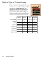
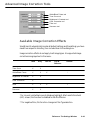
Define Type of Output Image
With your original properly displayed in the preview
window, you have to specify the image category in
which you wish to convert and output your original.
To do this, click the Scan Type button. SW 5Standard offers four options of image conversion
formats as shown at right. However, not all
categories of the originals listed in the Original
button menu can be converted into all of the listed
conversion formats as shown in the table below.
4-6
True Color
Web Color
Gray
Black & White
Text Document
X
X
X
ü
Graphics
ü
ü
ü
ü
Photo
ü
ü
ü
ü
Magazine
ü
ü
ü
ü
Art Magazine
ü
ü
ü
ü
Newspaper
ü
ü
ü
ü
Positive Film
ü
ü
ü
X
Negative Film
ü
ü
ü
X
Microtek ScanWizard 5
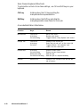
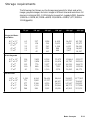
Resolution of Output Image
Click and use the resulting menu that pops up
when you click the Purpose button to define
the resolution for your output image. SW 5Standard provides default or predefined
resolutions (based on the ultimate purpose or
application, e.g., screen display, printing, etc.)
that closely match with the image type of your
original scan material (as defined under
Original button menu).
Select from the menu the particular setting that
will best match with the intended device
application for your output image. Different
types of original may have different predefined
values of resolution for certain device
applications as shown in the following table.
Text
Document
Photo and
+ / - Film
Select "Custom" and
enter custom resolution
in the Edit box
Graphic and
Magazine
Normal Screen
72 dpi
72 dpi
72 dpi
Fine Screen
96 dpi
96 dpi
96 dpi
Ink Jet Printer
300 dpi
200 dpi
300 dpi
300 Laser Printer
300 dpi
100 dpi
300 dpi
600 Laser Printer
600 dpi
150 dpi
300 dpi
Fax
200 dpi
200 dpi
200 dpi
OCR
300 dpi
300 dpi
300 dpi
If none of the predefined resolution matches with your need, you may define
your own resolution by selecting 'Custom' and then enter your own resolution
value in the Edit box provided at the bottom of the menu. Remember that the
higher the resolution, the larger the resulting file will be.
Your First Scan-Standard
4-7
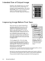
Intended Size of Output Image
By default, SW 5-Standard scans your original
into an actual size (100%) output image. To
change the output image dimension, click on the
Scale Output button. From the resulting menu,
select the predefined scaled size that best
matches your intended image output dimension.
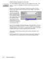
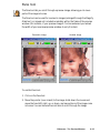
Improving Image Before Final Scan
When you scan your original image without
making any adjustments of your own, SW 5Standard will auto process to enhance the
quality of your digitized image by using its
default image editing settings. If you are not
satisfied with what SW 5-Standard has done for
you (as reflected in the preview image), you
may modify the default artwork and apply your
own image manipulation before final scanning
by using the image correction tools panel under
the Adjust button.
Reset icon. Use this icon
to individually reset the
Click the Adjust button. When the image
adjustment you have made
correction panel displays, adjust the preview
to each image correction
image by dragging the pellet button of each tool
tool, back to its default
setting.
along its groove. Observe a live update taking
place with your preview image as you
manipulate each of the image
correction tools. To reset a correction tool back to its original position, click on
the reset icon at right end of each tool (see figure at right).
Note that the new settings are automatically saved and will remain in effect for
the subsequent scanning sessions (after a reboot) unless otherwise redefined or
if they are reset to default settings (as explained in the following section).
4-8
Microtek ScanWizard 5
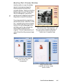
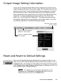
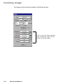
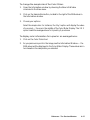
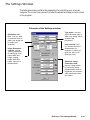
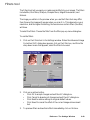
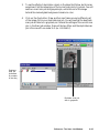
Output Image Setting Information
As you perform adjustments and define various settings for the output of your
original image (as reflected in the preview image), SW 5-Standard monitors and
makes records of them. Part of the defined settings are displayed in the Status
Bar (at the bottom of SW 5-Standard window) as soon as changes are made,
while a separate and more comprehensive record of the changes are kept at the
same time. To view a complete record of your settings, click on the Information icon [ i ] at the left end of Status Bar. The Image Information window
then appears, listing all the current setting for your output image. If you have
not made any adjustment, the default settings will display.
Drag this corner to resize
preview window
Status bar showing summary
settings for output image
Click icon to display detailed
info box (right)
Reset and Revert to Default Settings
When you feel like abandoning the adjustments you have just made, you can
easily revert to SW 5-Standard default settings and start all over again. Click on
the Reset button. All changes you have made in the menus and control panels
under Original, Scan Type, Purpose, Scale Output, and Advance buttons are
then reset back to SW 5-Standard defaults.
NOTE The settings you have made to dialog boxes under
Preference and Scan/Scan to/Copy/E-mail buttons are not
affected with the execution of the Reset button.
Your First Scan-Standard
4-9
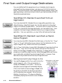
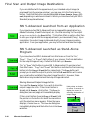
Final Scan and Output Image Destinations
If you are satisfied with the appearance of your intended output image (as
previewed from the preview window), you may now click the final scanning
button. Note that the button may be designated as Scan, Scan to, Copy, or Email, depending on what environment in which you have launched your SW 5Standard (as explained below).
ScanWizard 5-Standard Launched from an
Application
If you have launched SW 5-Standard from an image editing application (e.g.,
Adobe Photoshop, Ulead PhotoImpact, etc.) the final scanning for the output
image is controlled by the Scan button. This button offers no option other than
to scan your original with the image adjustments you have made (if any). Upon
completion, the output image is delivered directly to your image processing
application. From your application, you may further edit and save the image.
ScanWizard 5-Standard Launched as StandAlone Program
If you have launched SW 5-Standard from Start menu or from the “Go”, “Scan”,
“Copy”, or “E-mail” start button of your scanner, the final destination for the
output image will vary. Default at first start up is Scan to.
“Go” or “Scan” start buttons invokes SW 5-Standard as if it were launched from
Start menu. “Copy” and “E-mail” start buttons switches the final scanning
button into the Copy or E-mail button respectively. The Copy button will
prompt you to send the output to printer, while the E-mail button will invoke
your e-mail editor and attach the output image file with it. However, these
destinations may be aborted and the output image redirected .
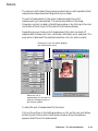
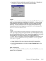
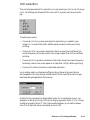
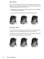
Storing Scanned Output Image to File
You need the Scan to button if you wish to store the
output image into a file. If the current button is
already set at Scan to, click button. The Save As
dialog box (see next page) will immediately display.
If the current button shows as Copy or E-mail, hold
the pointer on the button for about two seconds or
until the selection menu appears. When the menu
displays, choose Scan to. The Save As dialog box
immediately displays and the button turns into Scan
to button.
4-10
Microtek ScanWizard 5
Hold pointer on the button
for about 2 seconds to
display the menu for
selecting destination of
output image
For batch scanning with an auto
document feeder (ADF) equipped
scanner, you may provide root
filename only. SW 5-Standard will
auto-suffix such root filename with
serial numbers to generate multiple
filenames for the scanned and saved
images in continuous sequence
When your scanner is equipped with
an automatic document feeder (ADF),
ticking this check box will enable the
auto-filename generation for the batch
scan-to-file images
Check to also invoke your application
(Photoshop in this sample figure).
After image is saved, application is
auto invoked with the saved image
opened
Applications Combo Box. Your
available image and Internet
application programs are autodetected and listed here. Select one
to further process your output image
You may modify the folder and filename in the Save in and Filename panes
respectively, then click the Save button. The final scan is performed and the
output image is saved to file.
NOTE By default, files are saved in a 'Data' folder located in
the same directory as your SW 5-Standard, or
Windows\Twain_32\ScanWiz5 directory.
If filenames already exist, the following dialog box will display
showing conflicting filenames.
Error message when saving
a single output image
Error message when saving multiple output
images from ADF-equipped scanner
Your First Scan-Standard
4-11
Routing the Saved Image to an Application
If during the save-to-file-stage, you decide to further edit your output image
with your image processor, or wish to send the image with your e-mail, or
insert the image with your web browser for inclusion in an HTML document,
just tick the check box (Send images to application..). Then select your
application from the Combo Box (see figure in previous page). When you click
on the Save button, final scanning and saving routine starts. When done, SW
5 Standard auto-launches the application you have selected from the Combo
Box. The application then auto-opens the recently saved image into your
application. If an E-mail application was selected, the image file is delivered to
your e-mail composer as an attachment.
SW 5-Standard is designed to auto-detect the following image and web processors from your hard disk and displays them in the application Combo Box:
Image Processor
Internet/Mail
Photoshop
PhotoDeluxe
Netscape Navigator
Netscape Messenger 4.6
PhotoImpact
Photo Express
Internet Explorer
QualComm Eudora Pro 3.x
Microsoft Imaging
ImageStar III
Outlook Express
PageKeeper Standard MS Picture It
Microsoft Outlook 97/98
Batch Saving of Outputs from ADF Equipped Scanners
If you are using a scanner equipped with the automatic document feeder (ADF)
that allows multiple scanning in continuous sequence, you can auto scan and
save output images in batches. Just tick the check box (Auto generate
filename...) to enable this feature before you click the Save button.
SW 5-Standard will auto-assign a serialized filenames for each of the batch
images and store them to files after they are scanned in sequence. You may also
provide your own root filename. SW 5-Standard will auto-suffix your root
filename with serial numbers (e.g., xxxx001.jpg, xxxx002.jpg, xxxx003.jpg,
etc.) as filenames for the saved images.
Batch Routing of ADF Outputs to an Application
You can also auto-send your multiple images in a batch to your application after
saving them. Tick the other check box (Send images to application...) for this
function and click the Save button. After the first image is scanned and saved
to file, the selected application is invoked and the image opened with it. SW 5Standard continues to scan each of the subsequent images in sequence. Each
output is saved to file as it is scanned, and opened (in same sequence as they
were saved) in your application in cascading formation.
4-12
Microtek ScanWizard 5
If an E-mail application is selected, multiple windows of the e-mail application
will open - one for each of the output files. That is, if you have five output
image files, five e-mail composer are opened with an image file attached to each
of them.
If an Internet Mail application was selected, the files are delivered to the
Microtek e-mail editor in one batch as multiple attachments.
Copy Output Image to Printer
You need the Copy button to send an image directly
to the printer. If the button is currently set at Copy,
click the button and the Print dialog box displays.
Otherwise, hold the pointer on the button for about
two seconds or until the selection menu appears.
When the menu displays, select Copy. The button
immediately turns into Copy button, followed by the
appearance of the Print dialog box. Click Ok button
to start printing.
Select "Fit to
Page" to print
and fill whole
page (image is
enlarged and
printed full page,
but may not print
proportionally)
Select "Center
Horizontally"
to print image
at the center
of right and
left edges of
the page
Hold pointer for about 2
seconds to display menu
for selecting destination
of output image
Select "Center
Vertically" to
print image at
the center of
top and bottom
edges of the
page
Your First Scan-Standard
4-13
Attach Output Image to an E-mail
You need the E-mail button to attach the output image to your e-mail. If the
button iscurrentlysetatE-mail, click button and the Save As dialog box
displays.
Otherwise, hold pointer on the button for about two seconds or until the
selection menu appears (see top-left figure in previous page). Then select Email from the menu.
The button immediately
turns into E-mail button
while the Save AS dialog
box immediately displays
with the application check
box enabled by default.
Click to select from the
combo box which e-mail
processor you are going to
use (see figure at right).
'E-mail' is the e-mail editor (Netscape Messenger, Microsoft Outlook, etc.) you
have previously installed in your host. If none is installed, only 'Internet Mail'
will be available from the combo box. See Appendix A for proper e-mail editor
installation and setup to ensure compatibility with ScanWizard 5.
'Internet Mail' is the Microtek provided e-mail processor embedded in the
ScanWizard 5.
Click the Save button to execute final scanning, saving output image to file,
and launching of your e-mail application with the output image attached.
4-14
Microtek ScanWizard 5
Setting Preferences in ScanWizard 5-Standard
When SW 5-Standard is launched for the first time, it will auto detect, by
default, the type of scan material you have placed in your scanner and
automatically performs a prescan on the original material. The prescan image is
then placed in the preview area of the SW 5-Standard window. At the same
time, it has a default window painted in "sky" blue tinted colors. You may
change all these default conditions using the options offered in the Preferences
dialog box described below.
NOTE The customized settings you have made will remain in
effect at subsequent SW 5-Standard start-ups until redefined.
Preference Dialog Box
The Preferences setup dialog box provides options on how you would like SW
5-Standard to handle your scan material when the program is launched. You
may also disable the balloon screen tip feature in this dialog box if you are
already well-acquainted with the function of each button.
From the Preferences dialog box, you can also access the Appearance setup
dialog box where coloring options are available for repainting your SW 5Standard window. This includes all the buttons and the window background.
Left-handed users may also relocate the button pane location from right to left
side of the window for added convenience.
To redefine Preferences setup, click on the Preferences button. When the
Preferences dialog box displays, pick your options as illustrated in the
following page.
Your First Scan-Standard
4-15
Uncheck to change prescan
image preview from auto to
manual operation
Uncheck to change image
detection and selection of the
original scan material, and
definition of output image type,
from auto to manual operation
Click to access Appearance
dialog box (see below).
Use it to repaint SW 5Standard window buttons
and background, and to
relocate buttons pane
location to accommodate
left handed user (see
below).
Check to disable screen
'balloon' tips function
Change the unit of
measurement for image
selection as displayed in the
status bar (bottom of SW 5Standard window)
Appearance Dialog Box
Use this dialog box as your coloring pallet to repaint your SW 5 Standard
buttons and window background. If you are left handed, you may reposition
the block of frequently used setup buttons from right to left side of the window.
Try repainting the window with your favorite colors and add fun to your
scanning.
Preview window where live
color updates are shown
You may click directly on the
background or on any other
particular item in the Preview
window you wish to repaint.
The clicked item is instantly
reflected on the color
definition pane below. You
may also scroll through the
Item menu to look for the
window item you wish to
repaint.
The Scheme pane contains
predefined coloring pattern
(default and user defined)
selections. Choosing from
these selections allows
instant color changes to the
whole SW 5-Standard
window.
4-16
Microtek ScanWizard 5
Click on appropriate radio
button to reposition the row
of commonly used buttons
to either left or right side of
SW 5-Standard window
Use Delete button to
delete the no longer
needed color patterns
(user defined only).
Click to display the color pallet
from which color is chosen to
repaint the window item
selected at left pane
Use Save As... button to
save your own defined
color patterns and add to
Scheme menu.
Click to display color pallet
from which color is chosen
to repaint the font of the
text on selected item
Saving Your Favorite Color Scheme
When you saved the custom color pattern you have just defined, the pattern is
added at the bottom of an existing list of color patterns under Scheme menu
(see figure at right).
When deleting color pattern items from the Scheme menu, you can only delete
the user defined items. The default items can not be deleted.
User-defined pattern
Your First Scan-Standard
4-17
4-18
Microtek ScanWizard 5
5
Your First Scan with
ScanWizard 5-Advanced
Launching/Exiting ScanWizard 5-Advanced
Launch ScanWizard 5 as described in Chapter 3 (page 3-3). Be sure to launch
from your image processor if you wish to further edit or manipulate the scanned
image with your application. Launch from your scanner start buttons,
ScanWizard 5 Assistant button, or Start menu if you are going to save, print,
browse, or e-mail the output image.
To quit ScanWizard 5, simply click on the [X] button at top right corner of the
SW 5-Advanced window.
Switching to Advanced Mode
When you start ScanWizard 5 for the first time, the Standard Mode panel will
default. To switch to Advanced Mode, click on the Switch icon on the Title bar
of the Standard Mode window (see figure below). Within a few seconds, the
current program exits and switches to the other control panel mode.
Click this icon to switch control
panels between Standard &
Advanced modes
Your First Scan-Advanced
5-1
The Main Windows of ScanWizard 5-Advanced Control
Panel
The ScanWizard 5-Advanced Control Panel has four major windows consisting
of the Preview, Settings , Information , and Scan Job Queue windows.
Information
window
provides
Settings
window where
pixels of the
prescan
parameters are
defined and
Advanced Image
Correction (AIC)
Preview window
has the commands
enhancing images
at scan stage
interfacing with the
scanner
Scan Job
Queue
window
provides
management
of scan jobs
The Preview and Settings windows will always appear automatically whenever
ScanWizard 5 is started up. The Information and Scan Job Queue windows will
appear when you bring up ScanWizard for the first time but will not reappear if
you have hide these windows the last time you ran ScanWizard. You may show
(or hide again) the Information and Scan Job Queue window by clicking on the
View menu (on Preview window menu bar) and click on Show (or Hide) Info/Scan
Job Window.
5-2
Microtek ScanWizard 5
Operating ScanWizard 5-Advanced Control Panel
NOTE Be sure you have the original image (or scan
material) properly placed on the powered on scanner
before launching ScanWizard 5.
1.
Perform a low-resolution preview.
Click on the Overview button to scan an image.
Scan Frame tool
Scan button
Prescan
button
Overview
button
Preview area
2.
Select the required scan area.
Click on the Scan Frame tool. With the pointer now a crossbar, move to the
image and define the scan frame (by holding down the mouse and dragging
it to draw a box). The scan frame will be enclosed by dotted lines and will be
the actual area that is scanned when you click on the Scan button.
Your First Scan-Advanced
5-3
3.
Select the image type.
Select the image type to be processed and scanned. You can put one image
type on the scanner and scan that in its original form, or you can scan it in
another form altogether. For example, you may have a color photo and scan
it in the same color mode, or you may scan it as a grayscale or line art
image.
Resolution
edit box
Image type
Output size
Image correction
tools
4.
Set output resolution and Output Size.
Output resolution: Enter a resolution setting in the Resolution edit box,
then press Enter.
Output size: Enter the Output width/height value, indicating the
relationship of the input dimension, scaling, and the resulting image size.
5.
[Optional] Perform a high-resolution preview for the current selected scan
area.
Click on the Prescan button to show the image in high resolution.
5-4
Microtek ScanWizard 5
6.
[Optional] Set Advanced Image Correction (AIC).
Click on any of the Advanced Image Correction (AIC) tools in the Settings
window. These tools allow you to adjust image features such as brightness
and contrast; black and white points; tone curve; hue or saturation; and lets
you apply various filters for special effects.
7.
Perform the final scan.
Click on the Scan button to scan your selected image. The scanned image is
delivered to your application.
NOTE Refer to section on “Final Scan and Output
Image Destinations” at the back of this chapter for
other output image destination options.
Your First Scan-Advanced
5-5
Scanning a single-bit image (line art or B&W diffusion)
1.
Perform a low-resolution preview.
Click on the Overview button in the Preview window. In moments, a
preliminary view of the image appears in the preview area.
Prescan
button
Frame tool
Scan button
Overview
button
Preview area
2.
Select the required scan area.
Click on the Scan Frame tool. With the pointer now a crossbar, move to the
image and define the scan frame (by holding down the mouse and dragging
it to draw a box). The scan frame will be enclosed by dotted lines and will be
the actual area that is scanned when you click on the Scan button.
5-6
Microtek ScanWizard 5
3.
Select the image type.
From the Settings window, at the Type drop-down menu, make your
selection.
Image type
Threshold button
Image correction
tools
4.
•
Choose Line art if you are scanning purely black or white images with
no shades of gray, such as pen-and-ink drawings, logos, and sketches.
Line art also applies if you're scanning an image with just one color (like
a mechanical drawing or blueprint).
•
Choose B&W Diffusion if you are scanning black or white images with
shades of gray. A B&W diffusion image is similar to the images you see
in newspapers — there is only black and white, but the eye is fooled
into seeing gray because of the way dots in the image are arranged.
Set Output Resolution and Output Size.
At the Settings window, set the resolution. For now, select 300 dpi. But for
optimal results, select a resolution that matches the resolution of your
output device.
5.
[Optional] Set Advanced Image Correction (AIC).
For line art only: Click the “Threshold” button in the Setting window.
6.
Perform final scan.
Click on the Scan button to scan your selected image. The scanned image is
delivered to your application.
NOTE Refer to section on “Final Scan and Output
Image Destinations” at the back of this chapter for
other output image destination options.
Your First Scan-Advanced
5-7
Scanning a grayscale image
1.
Perform a low-resolution preview.
Click on the Overview button in the Preview window. In moments, a
preliminary view of the image will appear in the preview area.
Prescan
button
Scan Frame tool
Scan button
Overview
button
Preview area
2.
Select the required scan area.
Click on the Scan Frame tool. The pointer now becomes a crossbar, move to
the image and define the scan frame (by dragging the mouse to draw a box).
The scan frame will be enclosed by dotted lines and will be the actual scan
area when you click on the Scan button.
5-8
Microtek ScanWizard 5
3.
Select the image type.
From the Settings window, select the image type to be processed and
scanned.
Image type
Image
correction tools
4.
Set Output Resolution and Output Size.
Output resolution: Enter a resolution setting in the Resolution edit box,
then press Enter.
Output size: Enter the Output width/height value, indicating the
relationship of the input dimension, scaling, and the resulting image size.
Printer Type
Recommended Resolution Setting
Inkjet (360 dpi)
240 ppi
Laser (300 dpi)
120 - 150 ppi
Laser (600 dpi)
200 - 300 ppi
Dye-Sublimation
Match with your printer's resolution
Imagesetter
at least 300 ppi
Your First Scan-Advanced
5-9
5.
[Optional] Perform a high-resolution preview for the current selected scan
area.
Click on the Prescan button to see the image in high resolution.
6.
[Optional] Set Advanced Image Correction (AIC).
Click on any of the Advanced Image Correction (AIC) tools in the Settings
window. These tools allow you to adjust image features such as brightness
and contrast; black and white points; tone curve; hue or saturation; and lets
you apply various filters for special effects.
7.
Perform final scan.
Click on the Scan button to scan your selected image. The scanned image is
delivered to your application.
NOTE Refer to section on “Final Scan and Output
Image Destinations” at the back of this chapter for
other output image destination options.
5-10
Microtek ScanWizard 5
Scanning an RGB color image
1.
Perform a low-resolution preview.
Click on the Overview button to preview image.
Prescan
button
Scan Frame tool
Scan button
Overview
button
Preview area
2.
Select the required scan area.
Click on the Scan Frame tool. The pointer now becomes a crossbar, move to
the image and define the scan frame (by dragging the mouse to draw a box).
The scan frame will be enclosed by dotted lines and will be the actual scan
area when you click on the Scan button.
Your First Scan-Advanced
5-11
3.
Select the image type
From the Setting window select the image type to be processed and
scanned.
Image type
Resolution
edit box
Output size
Image correction tools
4.
Set Output Resolution and Output Size
Output resolution: Enter a resolution setting in the Resolution edit box,
then press Enter.
Output size: Enter the Output width/height value, indicating the
relationship of the input dimension, scaling, and the resulting image size.
5-12
Printer Type
Recommended Resolution Setting
Inkjet (360 dpi)
240 ppi
Laser (300 dpi)
120 - 150 ppi
Laser (600 dpi)
200 - 300 ppi
Dye-Sublimation
Match with your printer's resolution
Imagesetter
at least 300 ppi
Microtek ScanWizard 5
5.
[Optional] Perform a high-resolution preview for the current selected scan
area.
Click on the Prescan button to see the image in high resolution.
6.
[Optional] Set Advanced Image Correction (AIC).
Click on any of the Advanced Image Correction (AIC) tools in the Settings
window. These tools allow you to adjust image features such as brightness
and contrast; black and white points; tone curve; hue or saturation; and lets
you apply various filters for special effects.
7.
Perform final scan.
Click on the Scan button to scan your selected image. The scanned image is
delivered to your application.
Your First Scan-Advanced
5-13
Important scanning notes
If you are not familiar with the scanning process, you may wish to review the
preceding pages first on the individual scanning tasks to get a feel for the
software and how it works. Also, if some of the concepts discussed in these
pages are not familiar to you, refer to Chapter 6, Reference section of the manual
for more detailed discussion.
For previews and scans
Using the Scan Frame tool
Familiarize yourself with the Scan Frame tool. This tool is used to crop preview
images for final scanning. You can also use the Scan Frame tool to create
multiple scan frames, and with the creation of multiple scan frames, this means
you are actually creating duplicate scan jobs (based on the current scan job).
Each scan frame (and its related scan job) can have its particular settings, so that
one scan job can be in grayscales; another in color with a certain brightness
setting; and yet another in color with a filter applied to it. You can create
multiple scan frames in a single image, or you can have several images and have
several scan frames spread out among the images.
5-14
Microtek ScanWizard 5
Using the Prescan action button
Familiarize yourself too with the Prescan button, which is ideal for enlarging the
preview image and previewing it in detailed, high resolution. The enlarged view
obtained from prescan is not the same as the view obtained from the Zoom tool,
which is simply an enlarged pixilated view in low resolution.
Prescan button
Your First Scan-Advanced
5-15
Fixed Scan Frame
If checked, the size of the scan frame remains the same as the current one. You
may, however, move the scan frame in the Preview window.
For previews and scans
Fixed Output Size
If checked, the image size (disk space) and width/height of the output size
remain the same. The output size determines the width and height of your image
when output to a device such as a monitor or printer. The output size can be
changed only if this option is unchecked.
Keep proportion
If checked, the aspect ratio (X:Y) is kept as 1:1.
Selecting the correct resolution
Before scanning an image, select the correct resolution setting. Remember that
overly high settings slow down your scanning and create huge unmanageable
files.
5-16
Microtek ScanWizard 5
For image correction
•
Use the powerful image correction tools to improve your image if necessary,
and familiarize yourself with the features of the Advanced Image Correction
(AIC) dialog box.
Image correction tools
While in the AIC dialog box, you can see thumbnails of the image, make
image corrections there, and see the effects of the changes (“before” and
“after” versions ) in realtime. If the Preview checkbox is checked, these
effects are reflected in realtime in the Preview image.
Your First Scan-Advanced
5-17
You can also switch from one tool to another within the AIC dialog box.
Familiarize yourself too with the various action buttons in the AIC dialog
box and how they work. This is important.
5-18
Microtek ScanWizard 5
For scan job queue
•
Use the flexibility provided by the scan job functions to manage your scan
jobs. With the Scan Job Queue Window, you can create new scan jobs, copy
settings for a duplicate scan job, save scan jobs as templates, and load the
scan jobs templates for future use.
•
To master the intricacies of the scan job functions, familiarize yourself with
the usage of the Scan Frame tool and the Smoked Glass Background
feature, both of which are linked to the functions of the scan job.
Your First Scan-Advanced
5-19
Scaling the view of an image
Click on the Overview button. When the preview image appears, do either of the
following:
Option 1: Enlarging the view
1.
Click on the Zoom tool. The cursor will change to a magnifying glass pointer
with a plus (+) sign in it.
2.
Move the pointer inside the image and click. The area where the pointer is
positioned is zoomed in, enlarging your view of it. Clicking successively will
enlarge your view of the image in ascending order on the zoom scale —
from 100% to 200%, to 400%, and 800%.
Zoom tool
5-20
Microtek ScanWizard 5
Zoom scale
Option 2: Reducing the view
To reduce your view of the image after it was magnified:
While holding down the Shift key on your keyboard, move the pointer to any
portion of the image, and click on the mouse. The magnifying lens will show a
minus sign (-) in it, at the same time reducing your view of the image. Clicking
successively will continue to reduce the image until it is scaled down to its
original size.
1.
In the Preview window, choose the Show Info window command from the
View menu.
2.
Click on the Zoom Level Display in the Information window. From the dropdown list, select your zoom scale — 100%, 200%, 400%, or 800%.
Zoom scale
Your First Scan-Advanced
5-21
Correcting images
The image correction tools are located in the Settings window.
Click on any of the image correction
tools to adjust your image. The AIC
dialog box will then appear.
5-22
Microtek ScanWizard 5
Using the Advanced Image Correction dialog box
When you click on any of the image correction buttons in the Settings window,
the Advanced Image Correction (AIC) dialog box appears. In this box, you can
do the following:
1.
See a thumbnail of the image captured by your scanner, and see how the
image changes when adjustments are applied to it. The “before” and “after”
images are the left and right thumbnails in the dialog box.
2.
Select another image correction tool by clicking on any of the buttons
displayed in the vertical toolbar on the right side of the dialog box.
3.
Click on an action button to achieve a particular effect.
OK
Accepts changes you have made and closes the AIC dialog box.
Cancel Abandons all changes and closes the AIC dialog box.
Reset
2a
Restores settings to default. The Reset dialog box appears, allowing
you to reset your settings.
Revert Cancels out the effects of the currently used tool. If you have used
three tools, for instance, Revert will preserve the changes of the
first two tools and ignore the changes made by the third.
Your First Scan-Advanced
5-23
Final Scan and Output Image Destinations
If you are satisfied with the appearance of your intended output image (as
previewed from the preview window), you may now click the final scanning
button. Note that the button may be designated as Scan, Scan to, Copy, or Email, depending on what environment in which you have launched your SW 5Standard (as explained below).
SW 5-Advanced Launched from an Application
If you have launched SW 5-Advanced from an image editing application (e.g.,
Adobe Photoshop, Ulead PhotoImpact, etc.) the final scanning for the output
im ageiscontrolledbytheScan button. This button offers no option other than
to scan your original with the image adjustments you have made (if any). Upon
completion, the output image is delivered directly to your image processing
application. From your application, you may further edit and save the image.
SW 5-Advanced Launched as Stand-Alone
Program
If you have launched SW 5-Advanced from Start menu or from the “Go”,
“Scan”, “Copy”, or “E-mail” start button of your scanner, the final destination
for the output image will vary. Default at first start up is Scan to.
“Go” or “Scan” start buttons invokes SW 5-Advanced as if it were launched
from Start menu. “Copy” and “E-mail” start buttons switches the final scanning
button into the Copy or E-mail button respectively. The Copy button will
prompt you to send the output to printer, while the E-mail button will invoke
your e-mail editor and attach the output image file with it. However, these
destinations may be aborted and the output image redirected .
Storing Scanned Output Image to File
You need the Scan to button if you wish to store the
output image into a file. If the current button is
already set at Scan to, click button. The Save As
dialog box (see next page) will immediately display.
If the current button shows as Copy or E-mail, hold
the pointer on the button for about two seconds or
until the selection menu appears. When the menu
displays, choose Scan to. The Save As dialog box
immediately displays and the button turns into Scan
to button.
5-24
Microtek ScanWizard 5
Hold pointer on button
for about 2 seconds to
display the menu for
selecting destination of
output image
For batch scanning with an auto
document feeder (ADF) equipped
scanner, you may provide root
filename only. ScanWizard 5Advanced will auto-suffix such root
filename with serial numbers to
generate multiple filenames for the
scanned and saved images in
continuous sequence
Tick this check box to enable the autofilename generation for the scan-tofile images
Check to also invoke your application
(Photoshop in this sample figure).
After image is saved, application is
auto invoked with the saved image
opened
Applications Combo Box. Your
available image and Internet
application programs are autodetected and listed here. Select one to
further process your output image.
You may modify the folder and filename in the Save in and Filename panes
respectively,thenclicktheSave button. The Final scan is performed and the
output image is saved to file.
NOTE By default, files are saved in a “Data” folder
located in the same directory as your ScanWizard 5Advanced, or Windows\Twain_32\ScanWiz5 directory.
If filenames already exist, the following dialog box will
display showing the conflicting filenames.
Your First Scan-Advanced
5-25
Routing the Saved Image to an Application
If during the save-to-file-stage, you decide to further edit your output image with
your image processor, or wish to send the image with your e-mail, or insert the
image with your web browser for inclusion in an HTML document, just tick the
check box (Send images to application..). Then select your application from
the Combo Box (see figure in previous page). When you click on the Save
button, final scanning and saving routine starts. When done, SW 5-Advanced
auto-launches the application you have selected from the Combo Box. The
application then auto-opens the recently saved image into your application. If
an E-mail application was selected, the image file is delivered to your e-mail
composer as an attachment.
SW 5-Advanced is designed to auto-detect the following image and web processors from your hard disk and displays them in the application Combo Box:
Image Processor
Internet/Mail
PhotoShop
Photo Deluxe
Netscape Navigator
Netscape Messenger 4.6
PhotoImpact
Photo Express
Internet Explorer
QualComm Eudora Pro 3.x
Microsoft Imaging
ImageStar III
Outlook Express
Photo Soap
MS Picture It
Microsoft Outlook 97/98
Batch Saving of Outputs from ADF Equipped Scanners
If you are using a scanner equipped with the automatic document feeder (ADF)
that allows multiple scanning in continuous sequence, you can auto scan and
save output images in batches. Just tick the check box (Auto generate
filename...) to enable this feature before you click the Save button.
ScanWizard 5-Advanced will auto-assign serialized filenames for each of the
batch images and store them to files after they are scanned in sequence. You
may also provide your own root filename. ScanWizard 5-Advanced will autosuffix your root filename with serial numbers (e.g., xxxx001.jpg, xxxx002.jpg,
xxxx003.jpg, etc.) as filenames for the saved images.
Batch Routing of ADF Outputs to an Application
You can also auto-send your multiple images in a batch to your application after
saving them. Tick the other check box (Send images to application...) for this
function and click the Save button. After the first image is scanned and saved to
file, the selected application is invoked and the image opened with it.
ScanWizard 5-Advanced continues to scan each of the subsequent images in
sequence. Each output is saved to file as it is scanned, and opened (in same
sequence as they were saved) in your application in cascading formation.
5-26
Microtek ScanWizard 5
If an E-mail application is selected, multiple windows of the e-mail application
will open - one for each of the output files. That is, if you have five output image
files, five e-mail composer are opened with an image file attached to each of
them.
If an Internet Mail application was selected, the files are delivered to the
Microtek e-mail editor in one batch as multiple attachments.
Copy Output Image to Printer
You need the Copy button to send an image directly
to the printer. If the button is currently set at Copy,
click the button and the Print dialog box displays.
Otherwise, hold the pointer on the button for about
two seconds or until the selection menu appears.
Hold pointer on button
for about 2 seconds
to display menu for
selecting destination
of output image
When the menu displays, select Copy. The button
immediately turns into Copy button followed by the
appearance of the Print dialog box. Click Ok button
to start printing.
Select “Fit to
Page” to print
and fill whole
page (image is
enlarged and
printed full page,
but may not print
proportionally)
Select “Center
Horizontally”
to print image
at the center
of right and
left edges of
the page
Select “Center
Vertically” to
print image at
the center of
top and bottom
edges of the
page
Your First Scan-Advanced
5-27
Attach Output Image to an E-mail
You need the E-mail button to attach the output image to your e-mail. If the
button is currently set at E-mail, click the button and the Save As dialog box
displays.
Otherwise, hold the pointer on the button for about two seconds or until the
selection menu appears (see top-left figure in previous page). Then select E-mail
from the menu.
The button immediately
turns into the E-mail
button while the Save AS
dialog box immediately
displays with the
application check box
enabled by default. Click
to select from the combo
box which e-mail
processor you are going to
use (see above figure).
'E-mail' is the e-mail editor (Netscape Messenger, Microsoft Outlook, etc.) you
have previously installed in your host. If none is installed, only 'Internet Mail' will
be available from the combo box. See Appendix A for proper e-mail editor
installation and setup to ensure compatibility with ScanWizard 5.
'Internet Mail' is the Microtek provided e-mail processor embedded in the
ScanWizard 5.
Click the Save button to execute final scanning, saving output image to file, and
launching of your e-mail application with the output image attached.
5-28
Microtek ScanWizard 5
6
Reference to
ScanWizard 5-Advanced
This chapter explains in details all the features offered by ScanWizard 5Advanced Control Panel. The reference information is organized into four
parts, each showing the four major windows of the program and their respective
detailed functions. The sequence of information is as follows:
• Preview window
• Settings window
• Information window
• Scan Job Queue window
NOTE: The ScanWizard 5-Advanced Control Panel is also referred to as "SW 5Advanced" throughout this chapter.
TWAIN Compliance
The ScanWizard 5 is a TWAIN-compliant program. This means that it conforms
to the TWAIN software industry standard for controlling imaging devices such as
scanners, film recorders, and video capture cards.
The TWAIN standard allows software applications and hardware imaging devices
to communicate directly. In practical terms, this means that when using an
application software that supports TWAIN, you can access the scanner through
ScanWizard 5. When a scan is performed, the captured image is automatically
delivered to your application. Hence, with a TWAIN-compliant application, you
do not have to leave the application you are working in. The scanner captured
image does not have to be saved and opened as a separate by your application
software. This allows you to scan images right into your favorite image-editing
application, word processor, spreadsheet, or any other TWAIN-compliant
application that makes use of images.
Reference: The Preview window
6-1
The Main Windows of ScanWizard 5-Advanced Control
Panel
ScanWizard 5 consists of four major windows: Preview, Settings, Information,
and Scan Job Queue.
The four windows appear automatically after the ScanWizard 5-Advanced
Control Panel is started up. The Scan Job and Information windows appear
when you bring up ScanWizard 5 at the first time. You may hide or show them
from the View menu and click on the commands Show Scan Job Window and
Show Info Window.
Settings
window
scanning
parameters for
image and
includes image
Scan Job
window
provides key
functions in
managing
scan jobs
6-2
Microtek ScanWizard 5
Information
window
provides
information
on the
Preview
image
Preview
window has
commands and
tools for
controlling the
scanner
Running ScanWizard 5-Advanced Control
Panel
To invoke ScanWizard 5, click on Start , Programs , select Microtek ScanWizard
5 for Windows , then ScanWizard 5 .
Alternatively, you may start up your image-editing software first. When the
application opens, choose the command for running ScanWizard 5 from your
application.
The Preview and Settings windows will always appear automatically whenever
the SW 5-Advanced is started up. The Information and Scan Job Queue
windows will appear when you bring up SW 5-Advanced for the first time but
will not reappear if you have hidden these windows the last time you run SW 5Advanced. You may hide or show them from the View menu and click on the
commands Show Scan Job Window and Show Info Window.
Quitting ScanWizard 5-Advanced Control
Panel
Quit SW 5-Advanced by clicking on the Close (X) box at top-right corner of the
Preview window.
SW 5-Advanced automatically saves the screen display status when you exit
from the program. Hence, during subsequent start ups of SW 5-Advanced, the
screen display will show the same display as the last time you exited from the
software. That is, if you had all four windows displayed the last time you quit,
SW 5-Advanced will show the same four windows (with the same on-screen
location) at next start up.
Reference: The Preview window
6-3
The Preview Window
The Preview window is the most prominent window of the four major windows,
and it includes the various commands and tools for controlling the scanner.
Elements of the Preview window
1
2
4
5
3
6
7
8
1
The Menu Bar includes the different
menus for setting up the scanner
(Scanner menu), controlling view
options (View menu), customizing the
software (Preferences menu), Image
Correction function (Correction menu),
and accessing on-line help (Help menu).
2
The Tool buttons simplify the
performance of certain tasks. The Tool
buttons are (left to right) Frame,
Magnify Glass, Pane, and Dropper.
3
The Action buttons generate a specific
action from the scanning software. The
Action buttons include Overview,
Prescan and Scan.
4
6-4
The Switch button allows you to switch
to Standard mode control panel.
Microtek ScanWizard 5
5
The Scan Material Status icon shows
your scan material, whether it's
reflective, positive, or negative.
6
The Preview window is where the
Overview or Prescan image appears
after you click on the Overview or
Prescan button.
7
Rulers are located on both sides of the
window to help you with measurement
and alignment. The ruler unit can be
selected by clicking on the arrow at
the 0,0 point of the rulers.
8
The Status bar shows you some
information for easier operation.
The Menu Bar
Reference: The Preview window
6-5
The Scanner Menu
The Scanner Menu lets you:
• Show your scanner model or select a scanner if you have multiple scanners
• Get information about your scanner
• Get information about the SCSI chain
Scanner Model
The top of the scanner menu displays the scanner model you're using and its
Scanner ID. If you have multiple scanners on your system, all the scanners are
shown with their respective Scanner IDs, and the current scanner is indicated by
a check.
Only one scanner can be accessed at a time. To switch among various scanners,
select the scanner to be used.
The scanner with its Scanner ID is
displayed. The current scanner is
marked by a check.
Some scanner models include multiple scanning lens, one for high-resolution
scanning (for specific area) and the other for low-resolution (for general use). If
the multiple lens scanner is detected, there will be a sub-menu for lens selection.
Choose either one that suites you.
Get Current Scanner Info
This command provides information about your current scanner. When you
choose this command, a dialog box appears showing the scanner model,
Scanner ID number, and firmware version.
6-6
Microtek ScanWizard 5
Scanner Probe
This command allows you to see the SCSI devices on your SCSI chain and the
Scanner ID number of the devices.
By default, all numbers are selected by the check boxes. To allow ScanWizard 5Advanced Control Panel to start up more quickly, select only the boxes that
match the Scanner ID of your scanner (or scanners, if you have multiple
scanners on your system). This will make the ScanWizard 5 bypass the numbers
for your other devices and focus effort on simply detecting scanners. If you're
not sure about which numbers to specify, check all the boxes.
The SCSI Chain dialog box
Click on the Probe
button to update
information or
mount a SCSI
device if it's not
showing in the
dialog box.
Select your
interface card
here.
SCSI devices are
shown with their
corresponding
Scanner ID
numbers.
To let
ScanWizard 5
start up more
quickly, check
only the boxes
that match the
Scanner ID of
your scanner.
To use the SCSI Chain feature:
1.
Choose the Scanner Probe command. The SCSI Chain dialog box will appear.
2.
If your scanner does not show, click on the Probe button. Make sure your
scanner is connected and turned on.
3.
Make sure too that the correct interface card is shown in the card selection
box. If not, choose the correct interface card.
4.
Check the box corresponding to your scanner or scanners. Click OK to
close the dialog box.
Reference: The Preview window
6-7
Exiting ScanWizard 5-Advanced Control Panel
To exit ScanWizard 5, click on the close box on the upper right side of the
Preview window.
Double-click here to exit
ScanWizard 5
6-8
Microtek ScanWizard 5
The View Menu
The View menu lets you:
• Get an overview or prescan view of an image
• Resize the Preview window
• Show or hide the Information and Scan Job windows
Overview Image
This command switches to Overview mode, lets you view the Overview image
among the scan jobs.
The Overview is a preview of your image as defined by the parameters set in the
Overview Setup command (in the Preferences menu). For instance, if your image
is 8" x 5" but the dimensions in the Overview Setup are 4" x 3", your overview
will be 4" x 3".
The maximum size of the Overview varies, depending on your scanner model.
For example, if the scan bed (the glass surface) of your scanner has a maximum
size of 8.5" x 11", the maximum Overview will be limited to those dimensions.
The size of the Overview can be changed by setting new dimensions in the
Overview Setup command. The new dimensions will take effect, however, only
with the next Overview. This means you need to click on the Overview button so
that the scanner does a new Overview; only then will you see the new
dimensions of the Overview.
Reference: The Preview window
6-9
Prescan Image
By default, the Prescan Image Command does not exist, unless you press the
Prescan button. Each prescan image belongs to the respective scan job.
In the above screen, the Untitled1 Prescan Image is resulted ever since you
clicked the Prescan button for a scan job named Untitled1.
When you select the prescan image item (e.g., Untitled1 Prescan Image), the
preview window switches to the Prescan mode.
6-10
Microtek ScanWizard 5
Resize Window to Fit
This command adjusts the Preview window to fit the Overview area.
In the example below, the Preview window is larger than the Overview area, as
denoted by the empty space below the vertical ruler. In other instances, the
Preview window may also exceed the Overview area if you manually enlarged
the Preview window (by dragging on the resize box).
To utilize window space more efficiently, use this command to resize the
Preview window.
Before resizing
After resizing
To use this feature:
Choose the command Resize window to fit in the View menu.
This command is available only if the current zoom level is 100%, and is disabled
if zoom is set to other levels. To verify the zoom level, open the Information
window and look up the zoom level.
Reference: The Preview window
6-11
Show/Hide commands
These commands allow you to switch between showing or hiding the Scan Job,
Information windows, and Status Bar on your screen.
To use this feature, choose the correct command from the View menu for
viewing a window. When the window appears, you can hide it by choosing the
particular Hide command for it.
The Setting Window always comes with the Preview window. You may bring the
Setting Window to the front by choosing it from the View menu.
6-12
Microtek ScanWizard 5
The Preferences Menu
The Preferences menu lets you:
• Choose the correct scan material
• Set up color matching system
• Set up White/black point parameters
• Hide/show auxiliary cursor lines
• Set up Overview mode parameters
• Set up Prescan mode parameters
• Fine-tune monitor gamma values
• Invert images on the screen
• Further settings
Reference: The Preview Window
6-13
Scan Material
This command allows you to select the correct scan material. Scan materials can
be classified into three types:
• Reflectives, such as photographs or prints.
• Positives, such as slides.
• Negatives, such as the negative film you use for your camera.
The default scan material depends upon the scanner you're using, and the
choices available to you in the Scan Material submenu will also depend on your
equipment.
For instance, the positive option appears only if you're using a Transparent
Media Adapter (TMA) with your scanner.
If you are scanning negatives or positives, make sure you specify the correct
scan material, or you will get inaccurate scanning results.
To use the scan material feature:
Choose the Scan Material command in the Preferences menu. From the submenu
that appears, select your scan material; a check will appear next to the selected
option. The selected option will also be shown in the Scan Material Status icon
(discussed below).
Note: If your Preview window is close to the right edge of your monitor, the Scan
Material submenu may appear on the left side instead of on the right (as shown above).
To resolve this, move the Preview window towards the left to create enough room for the
submenu to drop down on the right.
6-14
Microtek ScanWizard 5
The Scan Material Status icon
Another way to access the Scan Material menu is to use the Scan Material Status
icon, located to the right of the Scan button.
Scan Material Status icon
The appearance of the Scan Material icon changes, depending on whether your
scan material is reflective, positive, or negative.
•
If you're scanning a reflective (such as a photo or print), this icon will
appear in its normal form like an ordinary icon. When you click on the icon
and hold down the mouse, you'll see the Reflective option checked.
Appearance of the Scan Material Status icon when scanning
reflective materials.
•
If you're scanning a positive transparency or filmstrip, this icon will appear
in the form of a positive. When you click on the icon and hold down the
mouse, you'll see the Positive Film option checked.
Appearance of the Scan Material Status icon when scanning a
positive transparency or filmstrip. Notice the perforations on the
top and bottom of the icon (characteristic of slides) to distinguish it
from the reflective icon.
•
If you're scanning a negative transparency or filmstrip, this icon will appear
in the form of a negative. When you click on the icon and hold down the
mouse, you'll see the Negative Film option checked.
Appearance of the Scan Material Status icon when
scanning a negative transparency or filmstrip.
Reference: The Preview Window
6-15
Color Matching Setup
To keep color consistency between the scanner, monitor, and printing device,
ScanWizard 5 applies Kodak CMS (Color management system) with ICC
(International Color Consortium) profile standards. For more information on
Color Management System, see Appendix C.
Color Matching Set Up command lets you select the correct ICC profile for
matching with your color monitor and color printer.
When you install ScanWizard 5, the default profiles of color monitor and printer
are set to sRGB. You may, however, update your settings from this command.
Monitor
This feature lets you select type of color monitor that is used for displaying RGB
data. The monitor profile will be applied only when “Displaying using monitor
compensation” option is checked.
Note: If the available monitor types do not include the one you have, select Generic P22
or Generic EBU. These two profiles are suitable for most of the monitors.
6-16
Microtek ScanWizard 5
RGB Destination
This feature lets you select the RGB output device (e.g., display monitor, or RGBbased printer) for matching RGB Color family images (including RGB colors, 48bit RGB colors, and 256 colors image types).
Display Using Monitor Compensation
This option controls how the RGB destination data is displayed. If unchecked,
the RGB data are displayed directly to the monitor. If checked, RGB data are first
compensated according to the selected monitor type, then send to the monitor.
RGB Color Matching
If checked, this option lets you select the type of RGB Destination for matching
RGB color image. If unchecked, all images, including RGB colors, 48-bit RGB
colors, and 256 colors, will be scanned in the image data without any color
matching processing.
Add Profiles
This command allows you add additional ICC profiles normally came with your
device (e.g., display monitor or printer).
Reference: The Preview Window
6-17
Select the profiles you need, then click on the Open button to load the profiles
to ScanWizard 5. This process takes a while for initialization.
Note: When you purchase color monitor or color printer, check to make sure your
supplier provides the corresponding ICC profiles.
Info
This command displays basic profile information for the current selected
devices.
6-18
Microtek ScanWizard 5
White/Black Points Setup
White point is a reference point that specifies the lightest area in an image,
making other areas to be adjusted accordingly. Likewise, black point is the
darkest reference area.
Auto White Point Clipping
Lets you set the percentage of pixel in the highlight region to be truncated.
Effective only when “Auto White/Black point” option is selected in the AIC
dialog box.
Auto Black Point Clipping
Lets you set the percentage of pixel in the shadow region to be truncated.
Effective only when “Auto White/Black point” option is selected in the AIC
dialog box.
Minimum Output level
Lets you set the minimum output level of the Black Point. The higher the
percentage value, the lower the contrast.
Maximum Output level
Lets you set the maximum output level of the White Point. The lower the
percentage value, the lower the contrast.
Reference: The Preview Window
6-19
Cursor Auxiliary Lines
This command allows you to create horizontal and vertical grid lines with your
cursor to help define a scan frame precisely. Using the grid lines, you can also
read the measurements off your ruler more easily.
Cursor auxiliary lines on the
x and y axis
To use this feature:
1.
Choose the Cursor Auxiliary Lines command in the Preferences menu. From
the submenu that appears, select how the cursor lines will appear.
• On both x (horizontal) and y (vertical) axes
• On x axis only
• On y axis only
• None (no cursor lines)
Note: If your Preview window is close to the right edge of your monitor, the Cursor
Auxiliary Lines submenu may appear on the left side instead of on the right (as shown
above). To resolve this, move the Preview window towards the left to create enough room
for the submenu to drop down on the right.
6-20
Microtek ScanWizard 5
2.
Click on the Frame tool.
To see how the cursor lines work, draw a scan frame. Click on the top left
corner of the image as your starting point, then drag down to form a scan
frame.
As you draw the scan frame, cursor lines will appear to help you draw the
scan frame precisely.
When you release the mouse, your scan frame will be aligned with the
cursor lines.
Click on the Frame tool, then
define a starting point.
Cursor lines appear to the
top and left of the image.
As you drag the mouse down,
the scan frame is aligned with
cursor lines on the x and y
axis (based on your selected
option in the submenu).
Reference: The Preview Window
6-21
Overview Setup
Specifies overview scanning speed options and the overview area for executing
the Overview command.
Fast Overview
The Fast option supports faster scanning with the sacrifice of overview image
quality; on the contrary, if Fast Overview is unchecked, Overview scanning
speed is slow, but it obtains better overview image quality.
Overview Area
Choose Maximum Size, other fixed dimensions, or choose Custom Size then
enter the required dimensions. You may also set the Overview Area by dragging
the dotted boarders.
Unit
Lets you set the ruler units such as inch, cm, and mm.
Preview
Click this button to get a scanning preview.
6-22
Microtek ScanWizard 5
Prescan Setup
This command allows you to set the parameters of scanning a prescan image.
Major difference between Overview and Prescan is, Overview button scans the
area specified in the Overview Setup command getting a low resolution preview
image; where Prescan button only scans the selected scanning frame, resulting a
more detailed preview image. When the Prescan Setup dialog box (below) comes
up, click on the option you need or specify your parameters.
Fast Prescan
If checked, you get an coarse image at a faster scanning speed; if unchecked,
you get a quality image with the sacrifice of scanning speed.
Prescan Image Margin
This option allows you to specify margin around the scan job in the first place,
subsequently you can adjust the scan frame slightly in the Prescan mode.
Available options are: None, Small, Medium (default), and Large.
Prescan Image Dimension
This option allows you to specify the size of the prescan image. Available options
are: Full screen, 75% screen, 50% screen, and Fit Preview Window. Size of the
Prescan image is not necessarily to fit into the specified option, it only is based
on the height/width ratio to get the maximum covered area.
Reference: The Preview Window
6-23
Monitor Gamma Setup
The Monitor Gamma Setup command lets you compensate linear intensity of the
monitor, making them consistent between preview image and the final scanned
image.
Monitor Gamma
Check this box to enable monitor gamma value setting.
When the monitor gamma option is checked, click the up/down arrow buttons,
making gray-level of the two boxes as close as possible. Click OK to confirm.
6-24
Microtek ScanWizard 5
Invert
This command creates a negative of an image. The Invert effect is applied to all
scan jobs, not just the selected scan job.
When an image is inverted, the brightness value of each pixel is converted to the
inverse value on the 256-step color values scale. For example, a pixel in a
positive image with a value of 255 is changed to 0, and a pixel with a value of 5 is
changed to 250.
Original
Invert
To use this feature:
Choose the Invert command in the Preferences menu. A check appears next to
the command when it is enabled.
Reference: The Preview Window
6-25
More command
The More command lets you specify rarely used, miscellaneous parameters.
Keep Overview Image
If checked, the image which is prescanned in the overview command remains on
the screen until next image acquisition is performed. If unchecked, when you
exit from ScanWizard 5, the overview image is deleted.
Keep All Prescan Image
If checked the image which is prescanned in the prescan command remains on
the screen until next image acquisition is performed. If unchecked, when you
exit from ScanWizard 5, the prescanned image is deleted.
Confirmation Message
If checked, a confirmation message appears when setting image effect functions
such as Rotate or Flip. If unchecked, the message does not appear.
Smoked Glass Background
This command helps you distinguish the current scan frame from the rest of the
preview image for greater visibility of the current scan frame.
With the Smoked Glass feature turned on, the part of the image within the
current scan frame will stand out, while the rest of the image (the “irrelevant”
material) is relegated to a background resembling smoked glass.
The Smoked Glass Background, then, helps you focus on the part of the image
within the current scan frame, and is particularly helpful when you are editing a
6-26
Microtek ScanWizard 5
scan frame or applying image-correction controls. This way, the changes can be
seen more clearly and stand out from the rest of the material. (See the next
section for more details. )
Current scan frame
(with pulsing lines)
Part of image not in
any scan frame and
also hidden by smoked
glass background
Scan Quality selection
During scan, you have these selections: Speed, Quality, and Best Quality.
Speed
Higher scanning speed results lower image quality.
Quality
If “Quality” option is selected, the scan head remains
stationary while CCD is exposed to light source. In a result, a
better image is achieved. Most scan materials can get a quality
scan if this mode is chosen.
Best Quality
This option is available for 10- or 12-bit scanners only. The
CCD exposure scheme is much the same as the “Quality”
option, yet the image correction is first applied on the 10- or
12-bit image, then being converted to 8-bit image. RGB Colors
(48-bit) image is always scanned in Best Quality option
regardless of any other option is selected. This option is useful
for scanning bad original and perform image correction
without loosing detailed information.
Note: This option is useful to scan Line art image that you want to keep the smooth edge,
e.g., Logo.
Reference: The Preview Window
6-27
Working Directory
Lets you specify a place to store temporary working files (e.g., scan job files)
during ScanWizard's session. If the directory you specify is not found or does
not exist, a warning message appears, and ScanWizard 5 will create a new one
for it.
If the computer is shared to use by many persons, each person may specify the
respective working directory of his own.
6-28
Microtek ScanWizard 5
The Help Menu
The Help menu lets you access on-line help for ScanWizard 5-Advanced
Control Panel.
The Help menu uses standard Windows conventions for obtaining on-line help.
If you are not familiar with this procedure, refer to your Microsoft Windows
user's guide.
About
This command gives you information on the ScanWizard 5-Advanced Control
Panel scanning software. ScanWizard 5 is also referred to in the About screen as
the ScanWizard 5 scanner controller.
Reference: The Preview Window
6-29
The Tool Buttons
Frame
Magnify Glass
Pane
Color Picker
6-30
Microtek ScanWizard 5
Scan Frame tool
The Frame tool lets you create a scan frame or multiple scan frames in the
preview image, which is the active area on which controls and commands can
be applied.
The Frame tool can also be used to create multiple scan frames, but only one
can be current at a time; the current scan frame is indicated by a marquee
(marching ants, or dotted boarders). The current scan frame can be more easily
distinguished if you turn on the Smoked Glass Background command (in the
Preferences menu).
Image with single scan frame
Current scan frame is denoted
by marquee
Image with multiple scan frames
Another scan frames,
which can be
distinguished by the
marquee around the
right half of the image.
This is not the current
scan frame, however, as
the part of the image
enclosed by the scan
frame is dimmed.
Smoked Glass
Background is on so that
the current scan frames
can be seen more
clearly.
Current
scan frame
Reference: The Preview Window
6-31
Scan Frame Keyboard Shortcuts
To get a better controls of scan frame settings, use Ctrl and Shift keys on your
keyboard.
Ctrl key
Holding down the Ctrl key and drag the
marquee results a square selection.
Shift key
Holding down the Shift key and drag the
marquee generates a new frame for a scan job.
A more detailed table is listed below.
6-32
Function
Keys
Result
Move/Resize
click+move
click+drag
Ctrl+click+drag
Move scan frame.
Resize scan frame.
Toggle between “Keep Square” and “resize”.
Change Job
click+move
click+drag
Ctrl+click
Change to the current job.
Select the job and set it to the current job.
Toggle between “Job selection” and
“make it as the current job”.
Redraw/Add
click+drag
Ctrl+click+drag
Shift+click+drag
Ctrl+Shift+click+drag
Redraw current frame.
Redraw current frame square.
Add new job.
Add new job in a square boundary.
Prescan
double-click
Change to the Prescan mode and set the
job as current.
Microtek ScanWizard 5
To use the Frame tool:
1.
Click on the Frame tool.
2.
Move the pointer (now a crossbar) to the preview image, and draw a frame
enclosing the area to be selected. When you release the mouse, the scan
frame will be in a marquee.
To make multiple scan frames (which would add scan jobs), hold down the
Shift key and drag the mouse. For more information on scan jobs, refer to
the Scan Job section of the Reference.
3.
To resize the scan frame, do either of the following:
•
Move the cursor to any corner of the frame; the pointer will change to
a double-headed arrow. Hold down the mouse, and drag to form a new
area, then release the mouse; or
•
Click on the Frame tool again and restart the area-selection process.
Reference: The Preview Window
6-33
Magnify Glass tool
The Magnify Glass tool enlarges your view of the preview image, allowing you to
set the scan frame with greater precision if you need to. Only your view of the
preview image is changed; the actual size of the image remains unaffected.
Each click of the Magnify Glass tool magnifies or reduces by a factor of 2. Thus,
the magnification levels increase from 100% to 200%, to 400%, and to the
maximum 800%.
Original image view
Image view enlarged with
Magnify Glass tool
To enlarge the view:
1.
Click on the Magnify Glass tool.
2.
Place the pointer — now a lens with a plus sign inside it — on the image
and click.
To reduce the view, hold down the Shift key and click again. The plus sign
changes to a minus sign when you hold down the Shift key.
Note: If the Information window is open, the zoom level will be indicated. This means
you can also zoom in by selecting the appropriate zoom level in the Information
window.
6-34
Microtek ScanWizard 5
Pane tool
The Pane tool lets you scroll through a preview image, allowing you to move
parts of the image into view.
The Pane tool can be used for zoomed-in images (enlarged through the Magnify
Glass tool), or images not included completely within the frame of the preview
window. (for instance, if your preview image is 7 inches wide and you resized
the width of your overview/preview window to only 3 inches).
Zoomed-in image
Scrolled image
To use the Pane tool:
1. Click on the Pane tool.
2. Move the pointer (now a hand) to the image. Hold down the mouse and
move the hand left, right, up, or down, and see portions of the image come
into view. You can also use the scroll bars to scroll through the image.
Reference: The Preview Window
6-35
Color Picker tool
The Color Picker tool allows you to sample color from an area in an image, also
useful for designating shadow or highlight point.
With the Color Picker tool, you can determine the color values for any pixel in
an image. When you click on the Color Picker tool, and pan over a pixel, the
value for that pixel is displayed in the Information window, based on the sample
size selected in the Information window. Pixel value information is useful
especially when you are making color adjustments based on color value.
6-36
Microtek ScanWizard 5
To change the sample size of the Color Picker:
1.
Open the Information window by choosing the Show Info Window
command in the View menu.
2.
Click on the Sample Size button, located to the right of the RGB values in
the Information window.
3.
Choose your options.
Select the sample size. For instance, the 1 by 1 option will display the value
of one pixel — the one in the middle of the Color Meter Display. The 3 X 3
option reads the average value of a 3-pixel by 3-pixel area.
To display color information for a pixel or an averaged area:
1.
Click on the Color Picker tool.
2.
As you pass over a point in the image, see the Information Window — the
RGB values will be displayed in the Color Meter Display. These values are in
turn based on the sample size you selected.
Reference: The Preview Window
6-37
Action Buttons
The Overview button scans a low resolution preview at a size
specified in the Overview Setup command.
The Prescan button performs high resolution preview for the
selected scan jobs.
The Scan button lets you scan the image in your scanner and
delivers it to your image-editing software. The scanned image
is based on the specifications you have chosen in the Settings
window and on controls you may have applied to the preview
image if a preview was performed.
6-38
Microtek ScanWizard 5
Rulers
The rulers on both sides of the preview window help you with operations that
need precise measurement and alignment of your image.
The unit of measurement in the rulers is determined by the unit of
measurement you have selected. This can be done either in the Image
Dimension controls, located in the Settings window, or by clicking on the ruler
unit button at the 0,0 point of the rulers in the Preview window.
Depending on your chosen unit of measurement, the rulers can mark off
measurement in these units: inch, centimeter, millimeter, point, and pixel. The
pixel option is dimmed if the selected resolution unit is lpi, and vice versa.
Pressing the ruler unit button displays
the measurement menu.
Select the unit of
measurement for the rulers in
either the Settings window or
the Preview window.
To select the unit of measurement for the rulers:
Click on the unit box in the Settings window, or click on the ruler unit button
at the 0,0 point of the rulers in the Preview window. When the submenu
appears, select the unit of measurement.
Reference: The Preview Window
6-39
Preview Area
The preview area is where the preview image appears.
The dimension of the preview area varies, depending on your scanner model.
The size can be changed, however, through the Overview Setup command in the
Preferences menu. You can increase the size of the preview area to see more
detail in your image, or you can reduce the preview area to save on memory.
For details on how to change the size of the preview area, refer to the Overview
Setup command in the Preferences menu section.
Preview area
6-40
Microtek ScanWizard 5
The Settings Window
The Settings window contains the parameters for outputting your scanned
image for the current scan job and includes the advanced image correction tools
of the program.
Elements of the Settings window
Resolution edit
box: Lets you enter
a resolution value in
which your image will
be output (not
scanned).
Image Dimension
controls: include
various parameters
for specifying scan
frame width and
height, scaling,
output width and
height, and unit of
measurement.
Type menu: Lets you
select the image type in
which your image will be
scanned and
processed.
Unit selection: Lets
you choose the unit of
measurement for
resolution in either ppi
(pixel per inch) or lpi
(lines per inch).
Advanced Image
Correction tools:
Improve image quality
by enhancing image
characteristics such as
brightness and contrast,
white and black points,
and others.
Reference: The Settings Window
6-41
Output Image Parameters
The Output Image Parameters include the various controls that determine how
your image is scanned and processed.
The Output Image Parameters include:
• Type
• Resolution
• Unit Selection
• Image Dimension controls
• Image Orientation controls
Type (Image Type or Scan Mode)
The Type menu determines what your resulting scan will be. It does not refer to
the original image mode. For instance, if you have a color photo but choose 256
grayscale for the scan mode, the photo is scanned and processed as grayscale.
To use the Type menu, from the Type menu, select your scan mode. Choose the
correct image type, as the wrong choice will simply create bigger files that won't
be of any use to you.
• If you have a grayscale original, do not set image type to RGB Colors (48-bit).
RGB colors are 24-bit, and RGB (48-bit) colors are used for applications
such as Photoshop 5.0.
Note: The options of RGB Colors (48-bit) and Gray Scale (16-bit) are available
only for 36-bit or above scanners, such as ScanMaker X6. Only a few applications
(e.g., Photoshop 5.0) in the market today support these two options.
• Web/Internet color is 256-indexed color image converted with uniform
palette and error diffusion. The sRGB (web color standards) profile is used
for color matching with this image type.
6-42
Microtek ScanWizard 5
• Customized 256 color option lets you select the attributes of indexed color.
If this option is selected, the following dialog box displayed.
Palette
Lets you choose the method of creating color palette table. “Uniform” uses 6-6-6
levels fixed color palette table, independent of the contents of the 24-bit RGB
image. By default, the “Adaptive” is selected, this option creates color palette
table from commonly used areas of the color spectrum that appears in the
image. Since colors in most images are concentrated in particular areas of the
spectrum, this option is generally used.
Dither
Lets you choose the dithering method. Dithering can further improves the 256index color image quality by mixing the available colors to simulate the missing
colors. “None” disables dithering; “Pattern” uses a structured pattern to simulate
the missing colors, this option is grayed out for Adaptive palette; and
“Diffusion”, which is the default, produces the best quality of 256-indexed color
image with lowering a little bit the scanning speed due to intensive algorithm
computation is required.
• Default attribute of 256-color is the last customized 256-color setting.
• B&W Diffusion image type is 1-bit B&W image dithered with error diffusion effect.
Save As 256 color
You may save the palette and Dither selections as the defaulted 256 colors, to be
selected from the Type menu.
Reference: The Settings Window
6-43
Resolution
Resolution in the Settings window refers to the desired resolution for outputting
the image to a device, such as a monitor or printer. It does not refer to the
resolution in which the image is scanned.
To set your resolution:
Enter a resolution setting in the Resolution edit box, then press Enter. If the
value you enter is too low or too high, the minimum or maximum resolution
value is entered for you instead.
According to the image type you select, default resolution is displayed. When
you specify the resolution you need, this value is recorded for subsequent use.
ScanWizard 5 records last 6 different resolution settings.
Note: In setting resolution, choose the setting that best matches your output device.
Remember that the higher the resolution, the larger the resulting file will be and the
longer it will take to output.
6-44
Microtek ScanWizard 5
Unit selection
The unit of measurement for resolution is in ppi (pixel per inch) or lpi (lines per
inch). Lpi settings are dimmed if the ruler unit is in pixels, and vice versa for
ppi.
To select your option:
• Choose lpi (1x) if you know precisely the resolution you need for your
image. Or, in case of Stochastic halftone and contone (continuous tone)
printing.
• Choose lpi (1.5x) to produce resolution that is one and one-half times the
screen frequency. Normally used on the screen higher than 133 lpi halftone
printing.
• Choose lpi (2x) to produce resolution that is two times the screen frequency.
Normally used on the screen equal to or less than 133 lpi halftone printing.
• Choose lpi Custom to produce customized resolution.
Lpi is widely used in professional offset printing. Values of ppi and lpi are
exchangeable. During scanning, ScanWizard 5 first converts the unit into ppi
before sending image data to the scanner.
Quality Factor represents multiplication factor for converting lpi to ppi. For
example, an 85 lpi printing is 127 ppi multiplying quality factor 1.5; or 170 ppi
multiplying quality factor 2. The Custom setting allows you to define values
from 1 to 4, decimal value is accepted, such as 1.33.
Reference: The Settings Window
6-45
Image Dimension controls
These controls allow you to adjust the various factors that affect the image,
including the width and height of your image when it is first scanned (Scan
Frame), the scaling factor, and the dimensions of the image in final output.
1.
Scan Frame (input) x Scaling = output: This mathematical formula
indicates the relation of the input dimensions to scaling and how these
factors affect image dimensions when the image is scanned.
To use the Image Dimension Controls:
•
Select the unit of measurement.
•
Enter a value in the applicable edit boxes (width input, height input,
scaling, width output, height output).
•
Scan Frame width and Scan Frame height refer to the dimensions of
the scan frame that you draw. For example, if the image on your
scanner is 5" x 7" and you draw a scan frame that is 3" x 4", then your
Scan Frame width will show 3.000 and your Scan Frame height will
show 4.000.
The Scan Frame width, Scan Frame height, output width, and output
height are affected by your scaling and whether you have checked the Keep
Proportion option or not.
2.
The Keep Proportion option allows you to keep the ratio of the image
width and height constant.
3. The Scaling control lets you create large or small images so that the images
don't have to be resized subsequently, which is usually done in your imageediting software. For more details, see the Basic Concepts chapter and the
Scaling section in the following pages.
6-46
Microtek ScanWizard 5
4. The Unit of Measurement allows you to select your unit of measure. The
options include inch, centimeter (cm), millimeter (mm), point, pixel, and
pica.
5. The Size indicates how big the file will be when you accept the dimensions
shown in the edit boxes, together with the resolution setting that you
selected. Size is calculated automatically.
Rotate and Flip tool
Click the “F” icon to bring up rotate and horizontal image flip selections. The
“F” icon represents the current selected orientation job.
Image effect of the Flip tool applies to the scanned image only, not the prescan
(or overview) image.
Reference: The Settings Window
6-47
How to use the Input-Output dimensions
The Input-Output dimensions consist of four edit boxes: Scan Frame width,
Scan Frame height, output width, and output height. These edit boxes are
linked to the use of Fixed Scan Frame, and the boxes may or may not be edited
depending on whether the Fixed Output Sized is checked or not. Below are the
details.
• Use the Scan Frame dimensions to specify your scan frame; or drag on the
scan frame to whatever size you want, and the dimensions will be reflected
in the Scan Frame width and height boxes.
• The output dimensions determine the width and height of your image when
output to a device such as a monitor or printer. The output dimensions can
be changed only if the Fixed Output Size is unchecked.
Scaling
Scaling is the process of creating larger or smaller images in your scanning
software so that you need not resize the images later when they are delivered to
your image-editing program.
To illustrate the use of scaling: Assume that your input dimensions are 4" x 5",
then:
• If scaling is at 100%, output dimensions will also be 4" x 5".
• If scaling is at 50%, output dimensions will be halved — to 2" x 2.5"
• If scaling is at 200%, output dimensions will be doubled — to 8" x 10".
The above assumes that your resolution is held constant throughout the
changes. When you change resolution and specify a value that has no exact
equivalent for scaling, the scaling may be affected and adjusts itself to the
nearest allowed value. For instance, if your resolution is 100, your scaling
becomes 99 (instead of a full 100), because that is the closest scaling equivalent,
given the resolution value.
6-48
Microtek ScanWizard 5
Advanced Image Correction Tools
White/Black Points tool
Tone Curve tool
Brightness & Contrast tool
Color Correction tool
Filter tool
Descreen tool
Available Image Correction Effects
ScanWizard 5 automatically locates all default settings and the settings you have
made from a specific directory, then include them to the dialog box.
Image correction effects do not apply to all image types. Unsupported image
corrections are grayed out in the menu.
RGB
Gray
Tone Curve
V
V
W hite/Black Points
V
V
Brightness & Contrast
V
V
Color Correction
V
Filter
V
V
Descreen
V
V
Line-art
B&W
Diffusion
Remark
V
*
V
**
*For Line-art, white/black points (shadow/highlight) effect results threshold
(AIC) screen; this function is disabled for B&W diffusion.
**For negative films, this function changes as Film Type selection.
Reference: The Settings Window
6-49
Introducing the Image Correction tools
With the image correction tools, you can adjust the characteristics of your image
right from within the ScanWizard 5. The image correction tools in ScanWizard 5
save you time and provide you with the needed flexibility to adjust images right
within the scanning software.
Although you can use all the image correction tools, you don't need to use
everyone of them to achieve a great image. Perhaps all that's needed is a change
in the shadows or gamma curve. Try experimenting with the tools to see which
one provides optimal results.
Using the Advanced Image Correction dialog
box
When you click on any of the image correction tools, or select Custom... in the
Settings window, the Advanced Image Correction (AIC) dialog box appears. In
this box, you can do the following:
6-50
1.
These are the thumbnails of the image captured by your scanner. The left
thumbnail is the “before” version — which shows the effects of the last
saved settings values. The right thumbnail is the “after” version — which
shows the effects of the new settings added in the AIC.
2.
To select another image correction tool, click on any of the buttons
displayed in the vertical toolbar on the right side of the dialog box.
3.
Click on an action button to achieve a particular effect.
Microtek ScanWizard 5
The Action Buttons in the AIC dialog box
The Action buttons in the AIC dialog box carry out a specific action.
1:1 Thumbnails
If checked, size of the thumbnail is about the same as the image shown in the
Preview window. If unchecked, the image size appears fit into the shown dialog
box.
Hide Thumbnails
If checked, the “before” and “after” thumbnails becomes hidden. To redisplay,
click the “Up” arrow at the left side of the dialog box.
Preview
If checked, the AIC image correction effect applies to the Preview image in real
time.
Reference: The Settings Window
6-51
The OK button
Clicking on this button will apply whatever Image Corrections you have
performed on the current scan job, and close the AIC dialog box.
Example : If you increased brightness, changed the saturation, and then clicked
OK, all the changes are applied, and you exit the AIC dialog box. The settings
are changed as Customized status.
The Cancel button
Clicking on this button will cancel out all image correction changes you have
made to the current scan job, and then close the AIC dialog box. The settings
remained unchanged.
Example: If you applied filters, changed the curve, and then clicked Cancel,
none of the changes will take effect, and you exit the AIC dialog box.
The Reset button
Clicking on this button brings up the Reset dialog box, where you can specify
which settings are to be reset, then click Reset or Cancel. If Reset is selected, the
settings are restored to their default values; if Cancel is selected, the operation
has no effect.
Example: If you changed white/black points, changed brightness, then clicked
on Reset and chose to reset brightness, the brightness setting of the scan job is
restored to its default; but the altered shadows and highlights remains in effect.
If you reset both white/black points and brightness, then those values are both
restored to default.
6-52
Microtek ScanWizard 5
The Revert button
Clicking on this button cancels out the changes you made with the current
image correction tool. This means that if you used several tools (and achieved a
look that is the cumulative effect of all the tools), using Revert will cancel the
effect of only the current tool and preserve the effects of the other preceding
tools.
Example: If you changed shadows, applied filters, changed brightness, then
clicked Revert, the brightness changes will be cancelled out, but the altered
shadows and filters settings remain in effect.
The Add to Menu button
Clicking on this button to save the settings you have made as a name. You may
retrieve this user-defined AIC setting afterwards from the Setting windows.
Maximum 20 sets of user-defined settings for each AIC function.
Example: Suppose you have set a White/Black Point for future use, at the
Description column, you input “24-bit color” string.
Reference: The Settings Window
6-53
To retrieve user-defined AIC settings
From Settings window, select the AIC settings you have made from the
respective AIC command.
Example: Suppose the White/Black Point settings of your input (e.g., 24-bit
color) is available for choosing.
To remove user-defined AIC settings
From Settings window, choose the AIC function, then select the Remove
Settings item.
A Settings dialog box appears.
Select the Settings you want to remove, click the Remove button.
6-54
Microtek ScanWizard 5
White/Black Points tool
For color and gray images, this tool allows you set white/black points; for lineart image, it carries out threshold adjustment feature.
The White/Black Points dialog box
(Color/Gray image)
Histogram
Pickers
Sliders
Auto
Histogram
The histogram is obtained from the scanned image material in the current
frame. The darkest pixels are at the left, and the lightest pixels are at the right.
An image with good contrast will have a histogram with vertical lines spread
across the scale from left to right. To change the white/black points, move the
two triangles below the histogram.
Channel selections are available for selecting respective color channel, or
selecting them all. Channel selections are accumulative, even though you select
both the “All” and the respective channels, the final effect is the “all” channel
plus the R, G, B, three channels. It is advisable to select either All or individual
R/G/B, not both.
Reference: The Settings Window
6-55
Sliders
If you would like to set white/black points by yourself, then drag the Sliders to
adjust Black and White points of an image.
Pickers
Instead of the sliders, you may use the Black and White pickers to set the Black
and White point values from the preview image.
Auto button
Clicking this button lets ScanWizard 5 automatically judges the darkest and
whitest points, and clips excessive white/black points. The clipping percentage
of the white/black points can be manually modified in the Preferences command
from White/Black Points Setup menu.
6-56
Microtek ScanWizard 5
The Threshold dialog box (Line-art image)
For line-art image, the White/Black point setting becomes as threshold setting.
Histogram
Sharpen
Threshold
The threshold values are in the range of 0 through 255.
Sharpen
This option lets you further enhance line-art image quality, if your original lineart material appears blur, for example, the text printed by inkjet, dot matrix
printer, or contains text with small point sizes.
Reference: The Settings Window
6-57
Tone Curve tool
The Tone Curve tool lets you control the gamma, which measures the intensity
affecting the mid-level grays (midtones) of an image.
Gamma is commonly used to describe the relationship between output density
to the original density across the mid-tones. Adjusting the gamma lets you
change the values of the middle range of gray tones without dramatically
altering the shadows and highlights.
In many ways, the Curve tool gives you the most control for adjusting an
image's values, but beginners may take some time to master its intricacies. The
Curve tool applies to grayscale and color images and is not available for use with
line-art or halftone scan modes.
How to read the curve
Original curve: Straight
diagonal line
Modified curve with
points moved up
The curve shows the relationship of the brightness changes across the middle
pixels between the resulting image and the original.
When you open the Curves dialog box, the line on the graph is diagonal
because the Input and Output values are the same.
The x axis of the graph represents the original brightness values of the pixels,
from 0 to 255, for 8-bit scanners (see the table on next page); the y axis
represents the new brightness values. Clicking on the diagonal line then plots a
point that can be adjusted.
6-58
Microtek ScanWizard 5
Scan
Original brightness value
8-bit color/Gray
0 - 255
10-bit color/Gray
0 - 1023
12-bit color/Gray
0 - 4095
When the curve is moved up or down, the relationship between input value and
output value changes accordingly.
• In areas where the curve is moved down, pixels in that portion of the image
are darkened.
• In areas where the curve is moved up, pixels in that portion of the image are
lightened.
Contrast in an image can be seen by the angle of the line. The steeper the slope,
the higher the contrast. The closer the line is to horizontal, the lower the
contrast.
Reference: The Settings Window
6-59
Sample images and their curves
Here, the original curve is a
straight diagonal, indicating that
input and output values are equal.
Here, points along the curve have
been moved up, so that pixels are
lightened as they are plotted to
new points.
For RGB image type, the net effect
creates a lighter image. For gray
scale image type, the net effect
creates a darker image.
Here, points along the curve have
been moved down, so that pixels
are darkened as they are plotted to
new points.
The net effect creates a darker
image. For gray scale image type,
the net effect creates a lighter
image.
6-60
Microtek ScanWizard 5
The Curve screen
Method
Channel
Curve
Curve
buttons
Curve
The Curve is a graphic representation of the gamma, showing scanner input
from dark on the left to light on the right.
Method
The Method sets the kind of curve you wish to have. Select from Line, Curve,
or Gamma.
Line
Curve
Gamma
Channel
The Channel allows you to choose the color or gray channel in which the
gamma will be affected.
Reference: The Settings Window
6-61
Input/Output/Zoom:
•
Input shows the input value of wherever the cursor is pointing on the
horizontal axis of the curve. In the example above, the cursor is pointing to
the middle of the curve, with a value of 136 on the 0-to-255 pixel scale.
•
Output shows the output value of wherever the cursor is pointing on the
vertical axis of the curve. In the example above, the cursor is pointing to
the exact middle of the curve, with a value of 119 on the 0-to-255 pixel
scale.
•
Zoom indicates the magnification level of the curve box. At 100% zoom,
the curve is seen in its entirety. Using the zoom frame tool (discussed next)
to magnify the curve will zoom in or enlarge your view of the curve,
resulting in a higher zoom percentage (for example, 200%).
Curve buttons
The Curve buttons let you modify the curve. The tools are (left to right) the
pointer, zoom frame, and hand.
6-62
Microtek ScanWizard 5
Using the Curve buttons
The Curve buttons allow you to modify the curve in the Curve screen. The tools
are the Pointer, Zoom Frame, and Hand.
• Use the Pointer tool to define points in the curve that will be modified.
When you click on any point in the curve, a control point appears to mark
your position. To remove a control point, drag it off the graph.
Pointer
Original
curve
Zoom
Frame
New control
points
• Use the Zoom Frame tool to zoom in on a particular point in the curve.
Once the area is zoomed in, you can then use the pointer tool to define new
points for more precision. This is particularly useful for working with 12-bit
images, as more detail can be seen in such images. The zoom level can be
seen in the Zoom column . To zoom out, hold down the Shift key and click
on the mouse simultaneously. Maximum scale is 1,600%.
• Use the Hand tool to scroll through the curve if the curve has been zoomed
in. The Hand tool can be used only if the curve has been zoomed in with the
Zoom Frame tool (above). Otherwise, the Hand tool will be dimmed.
Hand
Reference: The Settings Window
6-63
Using the Curve tool
2
1
4
3
6
5
1.
2.
Choose the channel in which the curve will be modified.
•
Select All to modify gamma in the color channels of the image
simultaneously. Depending on the image type you select, the color
channels can be “All, R, G, B”.
•
Select color channels individually (red, green, blue) to modify gamma in
that particular color channel.
•
For grayscale scanners, only the gray channel is available.
Choose the Method in which the curve will be modified; select from “Line
or Curve” or Gamma. Note that “Line or Curve” and Gamma is exclusive to
each other.
There is no difference in the method you select, and the choices are
provided to give you more flexibility in adjusting the curve.
6-64
3.
Choose a curve button; select from Pointer, Zoom Frame, or Hand. (See
previous section Using a curve button for more details.)
4.
Click on the curve to define the points where the curve will be modified.
You can then either raise or lower the curve at that point and see changes to
the image accordingly.
Microtek ScanWizard 5
5.
6.
Click on an action button.
•
Click OK to accept changes and exit the AIE dialog box.
•
Click Cancel to abandon all changes and exit the AIE dialog box.
•
Click Reset to restore settings to original default values.
•
Click Revert to cancel the effect of the current image-enhancement
tool.
To save a curve, click on the Save As button. A dialog box will appear.
•
Save the curve in Microtek formate. The Microtek format allows you to
have as many as 32 control points in the curve for more precision;
Photoshop allows a maximum of 19.
•
Choose the Channel. Select All if your channel (in #1) is All; select
Current if you selected one of the three color channels (red, green or
blue).
Click the “Add to menu” button to add the curve to the Tone Curve pop-up
menu in the Settings window.
To use a previously saved gamma curve for another image, click on the AIC
command, then choose the curve to be loaded.
Reference: The Settings Window
6-65
Brightness and Contrast tool
The Brightness and Contrast tool changes the brightness, contrast of the entire
image.
Brightness
The Brightness control lets you change the brightness setting. Too much
brightness can make an image look washed out.
Contrast
The Contrast control lets you change the contrast setting.
• High contrast can make an image look like a photocopy of a picture with
little or no gray shades.
• Low contrast can make an image look dull and flat.
• Very low brightness levels can make an image look very dark.
Individual channel adjustment for brightness/contrast is not supported. For
RGB color image, the same effect applies to all channels. For Lab color image,
brightness and contrast applies to L (Lightness) channel only.
6-66
Microtek ScanWizard 5
Color Correction tool
This tool changes hue and saturation of the image. The Color Correction tool
lets you click on the preview image to remove the unwanted color cast. The
parameters needed to balance the clicked pixel is reflected on the color wheel,
angle and radius values are updated accordingly.
The Color Correction tool is useful when the image has a particular color cast
and you wish to remove the cast to make the image look neutral.
Picker
Color Wheel
Saturation bar
Color Wheel
The Color Wheel shows you the position of colors — green is across magenta,
and red is across cyan. By moving the pointer (a small dot in the center of the
wheel) to another place in the color wheel, the hue of the image is altered. For
instance, if you move the pointer towards the green area of the wheel, the image
will acquire a greenish cast.
Saturation bar
The Saturation bar lets you change the intensity of the hues (colors) in your
image. Use Saturation selectively, because increasing saturation will intensify all
hues in the image.
Picker
The Picker lets you pick up a color from the Preview image, and make this color
to closer gray.
Reference: The Settings Window
6-67
Using the Color Correction tool
1
2
3
6-68
1.
To change the hue of an image, move the pointer in the color wheel to its
new color position in the wheel.
2.
To change the saturation of an image, drag on the saturation bar. Dragging
the slide bar to the left decreases saturation; dragging it to the right
increases saturation.
3.
Click on an action button.
•
Click OK to accept changes and exit the AIC dialog box.
•
Click Cancel to abandon all changes and exit the AIC dialog box.
•
Click Reset to restore settings to original default values.
•
Click Revert to cancel the effect of the current image-enhancement
tool.
Microtek ScanWizard 5
Filters tool
The Filters tool lets you apply or create special effects to your images. The filters
include Blur, Blur More, Sharpen, Sharpen More, Edge Enhancement, and
Emboss.
The image you obtain in the preview when you use the Filters tool may differ
from the way the image will appear when you scan it in. This depends on your
resolution, and the higher the setting, the less obvious certain filters (like Blur)
will have.
To select the filters: Choose the filter from the filter pop-up menu dialog box.
To use the filters:
1.
Click on the Filters tool in the Settings window. When the Advanced Image
Correction (AIC) dialog box appears, click on the Filter box, and from the
drop-down menu that appears, select the filter to be used.
2.
Click on an action button.
• Click OK to accept changes and exit the AIC dialog box.
• Click Cancel to abandon all changes and exit the AIC dialog box.
• Click Reset to restore settings to original default values.
• Click Revert to cancel the effect of the current image-enhancement
tool.
3.
To preview filters and see their effects immediately, click on this box.
Reference: The Settings Window
6-69
Blur filters
The Blur filters eliminate noise in the parts of the image where significant color
transitions occur. The Blur filters decrease the contrast between adjacent pixels,
making the image appear hazy and out of focus.
• Blur smooths out the transitions by lightening pixels next to the hard edges
of defined lines and shaded areas.
• Blur More produces an effect three or four times stronger than Blur.
Original
Blur
Blur More
Sharpen filters
The Sharpen filters do the opposite of the Blur filters and increase the contrast
of adjacent pixels, making images appear sharper and more focused.
Both Sharpen and Sharpen More filters improve clarity. The Sharpen More filter
has a stronger sharpening effect than the Sharpen filter.
Original
6-70
Microtek ScanWizard 5
Sharpen
Sharpen More
Edge Enhancement filter
The Edge Enhancement filter gives greater contrast to edges. The filters can do
this because edges are usually areas in an image where gray or color levels
change abruptly. It is best to use this tool for improving geometrical contouring
shape.
Original
Edge Enhancement
Emboss filter
The Emboss filter makes a selection appear raised or stamped by suppressing
the color within the selection and then tracing its edges with black.
Original
Emboss
Reference: The Settings Window
6-71
Descreen
Descreen allows you to remove moiré patterns in images.
A moiré is an undesirable pattern in printing that results from incorrect screen
angles of overprinting halftone. Moiré usually result when you scan images
taken directly from a magazine (instead of scanning a continuous glossy
photographic original or a transparency).
Before Descreen
After Descreen
To use Descreen:
1.
Click on the Descreen pop-up menu.
2.
When the Descreen menu comes up, select the screen for your needs.
•
Choose Newspaper (85 lpi) if the original image has a coarse dot
pattern (like images in a newspaper).
•
Choose Magazine (150 lpi) for images with a finer dot pattern.
•
Choose Art Magazine (175 lpi) for images with near-photographic
quality with a very tight dot pattern.
•
Choose Custom to set your own descreen options.
A check appears next to the descreen option that is enabled.
Clicking the “Add to Menu...” brings up a dialog box for your saving
the descreen as a name for future retrieval.
6-72
Microtek ScanWizard 5
The Information Window
The Information window is a floating window that provides preview image
information at the cursor location. It also allows you to change zoom levels
directly, in much the same way like using the Magnify Glass tool in the Preview
window.
To display the information window, click on the Show Info window command in
the View menu in the Preview window.
Elements of the Information window
Zoom Level Display
Cursor Locator
Sample size button
Output value
Pixel Display
Reference: The Information Window
6-73
Zoom Level Display
The Zoom Level Display shows the magnification levels possible from 100% to
a maximum 800% view.
Cursor Locator
The Cursor Locator shows where the cursor is on the coordinates along the x
(horizontal) and y (vertical) axis, based on the unit of measurement selected for
the rulers. This feature is useful for operations that require very precise
measurements and alignment.
Output value
This data indicate the output values of the selected image type. The image type
is selected from Settings window. The value at the left side is the image data
before processing by White/Black points, Tone Curve, Brightness/Contrast, Color
Corrections, and Filters. At the right side is the image data after the processing
(White/Black points, Tone Curve, Color Corrections, and Filters) .
Indications of output value range depend on output image types. See the table
below.
6-74
Image Type
Pixel Range
8-bit color
0 - 255
10-bit color
0 - 1023
12-bit color
0 - 4095
Gray Scale
0 - 255%
Microtek ScanWizard 5
Sample size button
The Sample Size button lets you choose how extensively the color information
will be read — whether it will apply to a single pixel or an averaged area.
Clicking the Sample Size button displays the sample size. The values as a whole
represent color information for the sample size selected in the Sample Size
button. For instance, if you chose 3 x 3 as your sample size and your R value
reads 23, that shows your red value of 23 is the average of a 3-pixel by 3-pixel
area.
Pixel-value information is useful when you are making image corrections based
on color values. Knowing this, you can modify the White and Black points of an
image, then come back to the same point in the image, and verify through the
output value that the image type values have indeed changed.
Using the Pixel Display
The Pixel Display helps you see how color pixels are organized and distributed.
The display can then help you make an informed judgment on how best to
modify image characteristics such as White and Black points, it also allows you
to verify any changes you have made.
Reference: The Information Window
6-75
The Scan Job Queue Window
The Scan Job window provides several key functions in managing your scan
jobs.
A scan job is simply a task that you designate the scanner to process and scan.
For instance, when you first preview an image, the image as a whole has its own
parameters (its own brightness and contrast setting, resolution, etc.). The whole
image can be treated as one scan job, or you can select part of the image, apply
different parameters to it, and treat that as a separate scan job. Scan job 1 can be
in color mode, while scan job 2 can be in grayscale mode.
By making the scan jobs distinct, you can then manage each job separately
(apply image correction, change settings, etc.) and scan them as separate files
into your image-editing software (if the software supports multiple open
images).
The number of scan jobs is indicated by the number of titles in the Scan Job
window. Scan jobs marked with a check are the ones designated to be scanned,
and the jobs are scanned in the order that they appear in the window.
Scan Job Queue window
This area shows the number
of jobs that have been
created. In this example,
there are two scan jobs.
Check marks indicate which
job or jobs are to be
scanned; the highlighted title
indicates the current scan
job. To rename a scan job,
highlight the title and type
over a new name.
Function buttons: The function buttons
allow you to create or manipulate the settings
for a scan job. These buttons include the Up
and Down position arrows; Duplicate, New,
Delete, Check, and Load/Save.
6-76
Microtek ScanWizard 5
Multiple Selections
Duplicate, Delete, and Check buttons allow multiple selections.
For multiple random selection, holding down the Ctrl key, then click the scan
jobs respectively; for sequential selection, click the “begin” scan job, then
holding down the Shift key, click the “end” scan job. The highlighted scan jobs
are selected.
Reference: The Scan Job Window
6-77
How to read the Scan Job window
3
1
2
1.
The example above shows three scan jobs.
•
The first scan job, entitled Untitled1, is a color image.
•
The second scan job, entitled Graylevel is a grayscale image.
•
The third scan job, entitled 24bit color, is a duplicate that shares the
settings of the first scan job.
The current scan job is the third scan job (24bit color), as it is highlighted.
This is also evident in the Preview window, as the third scan job is the one
enclosed by the current scan frame.
2.
All three scan jobs will be scanned, as each is marked with a check. To
change the order in which the jobs will be scanned, use the Up and Down
position arrows to change the sequence of the titles.
Note: The Smoked Glass Background feature is turned on in the above
example to mark clearly the current scan job.
3.
6-78
The image-type icon in front of the scan job title shows the scan job type
whether it is color, grayscale, line art, or halftone. A color scan job will have
a color image-type icon; a grayscale scan job will have a gray image-type
icon; and a line art or halftone scan job will have its corresponding imagetype icon.
Microtek ScanWizard 5
The New button
The New button lets you create a new scan job; the new scan job will have
default settings. This feature allows you to create as many scan jobs as you wish,
and each scan job can then have its own settings.
A scan frame may already be present after you click on the Overview button and
the preview image appears.
You can then simply grab one of the corners of the scan frame and drag towards
the left to form the scan frame described above. You can also click on the Frame
tool and redraw the frame. Both methods will work.
In the following example, we will use a single image and then divide it into two
parts: the left half of the image will comprise one scan job and will be in color;
the other half of the image will make up the second scan job and will be in
grayscale.
To use the New button:
1.
Click on the Overview button to see a preliminary view of the image.
2.
When the preview image appears, draw a scan frame that covers the left half
of the image. At this time, your scan job area shows the title of the current
scan job (Untitled1). Make sure the image type selected (in the Settings
window) for this scan job is RGB colors.
Scan frame around left
half of image. This
corresponds to the
current scan job in Scan
Job window.
Reference: The Scan Job Window
6-79
3.
Click on the New button in the Scan Job window. When a dialog box comes
up, give a title to the new scan job, then click OK. In this example, we will
call the new scan job Untitled2. The Scan Job window will now have two
titles. At the same time, a new scan frame appears in the preview window.
New scan frame appears
with the addition of a new
scan job. Two titles now
appear in the Scan Job
window.
4.
Draw the second scan frame around the right half of the image. In this case,
confine the scan frame to the upper right half; leave the lower right half
free. The reason why will become apparent in the next step. (For details on
drawing the scan frame, see the Note that comes after #2.)
Draw second scan
frame around upper
right half of image.
6-80
Microtek ScanWizard 5
5.
With the title bar in the Scan Job window highlighting the second scan job,
go to the Settings window, then choose Grayscale in the Type box. Next, go
to the Preferences menu in the Preview window, choose More command,
and enable the Smoked Glass Background command.
You will now see the following:
Left half of
image (first scan
job) is in color.
•
The second scan job (the upper right half of your image) is in
grayscale.
•
The first scan job (the left half of the image) remains in color.
•
The lower right half of the image (the part not included in any scan
frame) is hidden behind the smoked glass background. The smoked
glass command is not essential for doing a scan job, but it helps you
distinguish scan frames more easily.
Upper right half of
image (second scan
job) is in grayscale.
Lower half of image
is not in any scan
frame
Reference: The Scan Job Window
6-81
6.
To see how the scan jobs relate to the titles in the Scan Job window, try this.
•
Click on the first scan job title. The scan job that becomes active will be
the left half of the image (in color). In the Scan Job window, the title
will be highlighted, indicating that it is the current scan job.
•
Click on the second title, and the second scan job is activated (upper
right-hand part of image, in grayscale). The second title will now be
highlighted because it will be the current scan job.
First scan job
(color)
Second
scan Job
(grayscale)
Clicking on the first title activates the first image. Clicking on
the second title will activate the second image.
7. To designate the scan job to be processed and scanned, select the scan job
and click on the Check button. The checked scan job(s) will then be
scanned in the order that they appear in the Scan Job window, and they will
be delivered separately to your image-editing software.
6-82
Microtek ScanWizard 5
More on the New button
The above example shows how to use the New button to create different scan
jobs. While the example makes use of creating two scan jobs from a single
image, with each scan job being a different image type, you can use the same
principle in different applications.
For instance, you can:
• Create two or more scan jobs from a single image. The scan jobs may be the
same image type (all color or all grayscale), but each job could have different
brightness and contrast settings, resolution, etc.
• Create different scan jobs from multiple images. Instead of one, you can have
two or more images and designate each image as a separate scan job. Image 1
could be color, image 2 could be grayscale, and image 3 could be line art.
When the three scan jobs are scanned, each is delivered into its own file.
When you have multiple scan jobs and designate all of them for scanning (all
scan jobs are checked), each job will be scanned once you activate scanning,
and each job is delivered to its own file in your image-editing software.
Reference: The Scan Job Window
6-83
The Duplicate button
The Duplicate button lets you duplicate the settings of a scan job. This function
is especially helpful if you have created optimal settings for a scan job and wish
to use these settings as a template for other scan jobs. This saves time, as you
don't have to create the settings repeatedly for every scan job you make.
Before using Duplicate, it is helpful to turn on the Smoked Glass Background
feature. This will allow you to see clearly the effects of duplication.
To use the Duplicate button:
1.
Click on the Overview button to see a preliminary view of the image. To
show the principle of duplication clearly, choose image type (in the Settings
window) as RGB colors. Also, turn on the Smoked Glass Background
feature (in the Preferences menu of the Preview window). Draw a scan
frame around a part of an image. This is your current scan job.
2.
Draw a scan frame around a part of the image. This is your current scan
job.
Draw scan
frame around
image part. This
is the current
scan job.
6-84
Microtek ScanWizard 5
3.
To see the effects of duplication clearly in the steps that follow, do this as an
experiment. Set the image type of the current scan job to Grayscale. You will
see the current scan job as a grayscale job, while the rest of the image
behind the smoked glass background remains in color.
4.
Click on the Dup button. Draw another scan frame around a different part
of the image; this is your duplicate scan job. You will see that the duplicate
scan job will also be in grayscale, as it shares the settings of the current scan
job. In the Scan Job window, there will be two titles, and the duplicate scan
job is the one with a number to it (ex. Untitiled1-1).
Duplicate
scan job
(indicated
by number
in the title)
Duplicate scan job,
also in grayscale
Reference: The Scan Job Window
6-85
The Delete button
The Delete button allows you to delete a scan job.
To use the Delete button:
1.
Click to select the scan job template for deletion. Multiple deletion is
permitted.
2.
Click on the Delete button, then click OK.
The Check button
The Check button allows you to select the scan jobs to be scanned. When you
then click on the Scan button to start scanning, the scan jobs marked by a check
are the ones that will be scanned. The Check button is a toggle.
To use the Check button:
1.
In the Job Title area of the Scan Job Queue window, select the scan job to
be scanned.
2.
Click on the Check button. A check will appear next to the selected scan
job.
3.
To uncheck a selection, select the scan job to be unchecked, and click on
the Check button again. The scan job will be unchecked, and the scan job
will not be scanned when you click on the Scan button.
Shortcut: To check or uncheck a scan job, you may toggle-select the Check icon
underneath the Status column.
Check
Uncheck
6-86
Microtek ScanWizard 5
The Save/Load button
The Save/Load button lets you save current scan jobs as templates, also let you
load the scan job templates you have saved.
To save scan job as a template:
1.
Click on the Load/Save button.
2.
At the right column, highlight the scan jobs you want to save.
Reference: The Scan Job Window
6-87
3.
Click on the Save button. The scan job templates are saved under the
directory shown at the upper left hand side. In this example, the directory
name is “C:\windows\twain_32\scanpro\data”. You may specify different
directories for respective scan job templates (e.g., 6x7 cm, 35mm, et. al.).
To load scan job templates:
1.
Click on the Load/Save button.
Other than the default directory, you can also click on the folder icon,
choose the directory for Load/Save
6-88
2.
You may remove your existing scan jobs at the right column before loading
the new scan job templates.
3.
At the left column, highlight the scan job templates you want to load. You
can put more scan jobs to left column by looking in default directory.
4.
Click on the Add button.
Microtek ScanWizard 5
New name auto given if the name already exists
When you load or save scan job templates, you may check or uncheck the “New
name auto given if the name already exists” option. Suppose the scan job
templates already exist, if you check this check box, the number suffix is
automatically appended as a new scan job. If unchecked, the existing scan job
templates are overwritten.
The Up/Down Position Arrows
The Up/Down position arrows allow you to change the sequence in which jobs
are scanned through changing the order of the scan jobs in the Title area.
To use the Up/Down position arrows:
1.
In the Title area of the Scan Job window, select the scan job to be moved up
or down.
2.
Click on the Up or Down arrow to change the order of the scan job in the
list. When you start scanning, the scan jobs will be processed and scanned
in the order that they appear in the Scan Job window (i.e., the first scan job
is scanned first; the second scan job is scanned second, etc.).
Reference: The Scan Job Window
6-89
Appendix
This section contains important information on product and support policies,
troubleshooting, and other scanner-related features. The following subjects are
covered:
• Configuring E-mail Software
• The Scanner Test Utility
• Microtek Scanner Configuration Utility
• Kodak Color Management System (KCMS)
• Basic Concepts
• Troubleshooting
• Glossary
Appendix A: Configuring E-mail Software
Overview
Currently, ScanWizard 5 "Scan to E-mail" supports the following MAPI
compatible e-mail applications:
• Netscape Messenger (aka Netscape Mail) 4.6 or later
• Microsoft Outlook 97/98.
• Outlook Express
• QualComm Eudora Light/Pro 3.x
When the ScanWizard 5 (both Standard and Advanced modes) “Scan to E-mail”
function is invoked either via E-mail button or from Save As dialog box,
ScanWizard 5 will auto-detect the presence of any of the above e-mail
application in your system and auto-launched such application with the
scanned image file automatically attached to its message window. Complete the
message with the recipient address and add accompanying text, then send it
out.
Note that ScanWizard 5 will be able to detect your e-mail application only if
such application has been defined as the default MAPI application of your
system. The sections below explain how to setup each of the supported e-mail
editors as your default messaging application programming interface.
Configuring E-mail Software
A-1
Setting Outlook Express as Default MAPI
1. Open Outlook Express
2. Select Tool from the menu bar
3. From the resulting menu, select Option
4. The command displays the Option dialog box which contains 7 tabs
5. Choose General tab and check the items on “default e-mail” as shown below
to assign Outlook Express as your default MAPI
Tick these check boxes
to make your Outlook
Express as your default
e-mail program and allow
ScanWizard 5 to autodetect and launch the
program during "scan to
e-mail' function
A-2
Microtek ScanWizard 5
Microsoft Outlook 97/98 as Default MAPI
Microsoft Outlook 97/98 does not have a function for setting itself as default
MAPI application, so there is no way to directly assign it as system default
MAPI. However, ScanWizard 5 will still be able to auto-detect the program if
any of the following conditions prevails:
•
You have installed no other e-mail application except Microsoft
Outlook 97/98.
•
You have installed other e-mail applications aside from Microsoft
Outlook 97/98, but none of them is setup to be your default MAPI.
That is, Microsoft Outlook 97/98 automatically becomes your default
MAPI-based unless otherwise other e-mail application in your system
has been manually defined to be the default MAPI to supersede
Microsoft Outlook 97/98.
NOTE If you have a number of e-mail applications in your
system, the last application to be defined as your default MAPI
will override the previously defined application.
Setting Netscape Mail 4.6 as Default MAPI
1. Open your Netscape Mail (aka Netscape Messenger) Version 4.6 or later
2. Click on Edit from the menu bar
3. From the resulting menu, select Preferences
4. From the resulting Preferences dialog box, check the items on “MAPI-based
applications" as shown below to define Netscape Mail as your default MAPI
Tick this check box to
make your Netscape Mail
as your default e-mail
program and allow
ScanWizard 5 to autodetect and launch the
program during "scan to
e-mail' function
E-mail
Editors
Setup
Configuring
E-mail
Software
B-3
A-3
Setting Qualcomm Eudora Light/Pro 3.x as
Default MAPI
1. Open Eudora Light or Eudora Pro 3.x
2. Select tool from the menu bar
3. From the resulting menu, select Option
4. The command displays the Option dialog box shown below
5. From the Category pane of the dialog box, select the icon on “MAPI.” Under
the “Use Eudora server:” selection pane, enable “Always.” or as illustrated
below
Select this item to make
Eudora as your default email program and allow
ScanWizard 5 to autodetect and launch the
program during "scan to
e-mail' function
A-4
Microtek ScanWizard 5
Attaching Scanned Images to Non-Supported
Commercial E-mail Applications
If your system does not contain any of the above applications, you can still send
your scanned image through the Internet using the ScanWizard 5 built-in
“Internet Mail” function. See Chapter 4, Section on Attach Output Image to an Email of the User's Manual for details.
You can also send your output image through other non-supported applications
by saving your output image into file using ScanWizard 5 “Copy to” function as
detailed in Chapter 3, Section on Storing Scanned Output Image to File of the
User's Manual.
Configuring E-mail Software
A-5
A-6
Microtek ScanWizard 5
Appendix B: Using the Scanner Test Utility
The Scanner Test is a utility included with ScanWizard 5 that allows you to
verify if your scanner has been properly set up and connected to your PC.
To start up the Scanner Test utility:
To start up the Scanner Test, click on the Start button to select Programs,
Microtek ScanWizard 5 for Windows, and Scanner Test.
When started up successfully, the screen below appears.
The Scanner Test Utility
B-1
Elements of the Scanner Test dialog box
1
1
2
3
6
4
5
7
1
The Scanner model indicates the scanner connected to your PC and the
scanner's Scanner ID. If you have multiple scanners hooked up to your
computer, the scanners will appear in the drop-down menu, and choosing
another scanner will update the image button (#6) accordingly.
2
The Interface Card indicates the scanner interface you're using. Choose
from the following:
If you have more than one SCSI card in your system, you can click on this
option to select which card the scanner is connected to.
3
B-2
The Hard Drive Configuration indicates the following:
•
Physical RAM : The amount of system RAM plus Windows virtual
memory.
•
Hard Disk Available : The amount of hard disk space left. The size
indicated here may or may not be the maximum file size that you can
have for a single scan.
Microtek ScanWizard 5
4
The Scanner Check button acts as a Scanner probe to verify the location of
your scanner and the scanner ID.
When you click on the Scanner check button, the dialog box below
appears, with the scanner and its corresponding Scanner ID displayed in
the correct location. If your scanner does not appear, the connection
between your scanner and PC may not be secure, causing the system not to
“see” the scanner. In this case, check all cables and make sure your scanner
is ready. You may also want to turn the scanner and computer off, wait for 5
seconds, then turn them on again to reset everything.
Your scanner as verified by Scanner
check
Click OK to close the dialog box
5
The Reconfigure Equipment button allows the system to update its own
internal reference file and is used if you have changed your setup or
reconfigured your system.
For instance, if you changed scanner models on your system (physically
removed a scanner model and attached a different one), the Scanner model
box (#1) will not show the change automatically unless you first click on
the Reconfigure Equipment button to update the system. Use this feature to
make quick updates; all changes are done internally and automatically.
The Scanner Test Utility
B-3
6
The image button shows a thumbnail of the scanner you're using. Clicking
on this button will activate your scanner and display whatever image is on
your scanner. The image is shown in the Scanner Test display (the area
above the image button), as shown below.
Image in scanner is
displayed here after you
click on the image button.
If you are using a scanner accessory such as a Transparent Media Adapter
(TMA) or Auto Document Feeder (ADF) with your scanner, this will also
show up as a second Image button. There will then be two Image buttons
— one for the scanner, and one for the scanner accessory you're using
(either the TMA or ADF).
Second image
button shows
up if your
scanner is
connected with
an accessory.
For Example,
TMA.
7
B-4
The Exit button allows you to leave the Scanner Test utility.
Microtek ScanWizard 5
How to use the Scanner Test utility
1.
Click on the Start button to select the “Programs/Microtek ScanWizard 5 for
Windows/Scanner Test” submenu. The Scanner Test dialog box will appear.
2.
Make sure your scanner model is shown in the Scanner model box (#1
element in preceding section). If you have multiple scanners hooked up on
your system, choose the correct scanner model to be tested. Take note of
the following:
•
If your scanner is not shown, check to make sure the connection is
secure between your scanner and the PC. You may want to use the
Scanner Check feature (#4 element) to see if your scanner can be
detected by the system. Click on the Scanner Check button to do this.
•
If you have a different scanner model than is being shown on the
Scanner model box, you may have changed your setup since the last
time. To update the system, click on the Reconfigure Equipment
button (#5 element). The correct scanner model should then be
displayed on the Scanner model box.
•
If the above measures still fail to display your scanner model, turn off
your scanner and computer, then wait 2-3 seconds and turn them on
again to reset everything. (Some scanner models may require at least 60
seconds after being turned off before they can be powered up again. If
your scanner model does not come to a ready state, see the
Troubleshooting section of the manual.)
•
Make sure the correct interface card is shown (discussed below in #3).
3.
Make sure the correct interface card is shown in the Interface Card box (#2
element).
4.
To start the scanner test:
•
If you only have one image button (showing you the flatbed scanner):
Click on the Image button (#6 element) to start the scan test.
•
If you're using a scanner accessory such as a TMA or ADF: Click on the
image button showing the accessory (instead of clicking on the button
showing the scanner). This will activate the scanning action on both
the scanner and the accessory.
The Scanner Test Utility
B-5
When the scan test is successful, the image in your scanner will appear in
the Scanner Test Display above the Image button area. This indicates that all
is well with your scanner. If no image appears, see the Troubleshooting
section of the manual.
Note: If you have an ADF, place a page inside the ADF but remove any material
from the scanner glass. Then press the ADF image button to start the test.
5.
B-6
To exit the Scanner Test utility, click on the Exit button (#7 element).
Microtek ScanWizard 5
Appendix C: Microtek Scanner Configuration (MSC) Utility
The Microtek Scanner Configuration (MSC) utility is a companion program of
ScanWizard 5. This utility works only if your scanner model is equipped with
either 3 or 5 buttons.
If your Microtek scanner is equipped with either three or five buttons, you can
use the buttons to complete common scanning tasks.
Things you need to know about the MSC
ScanWizard 5 and MSC are running exclusive of each other. ScanWizard 5 will
not function correctly with the MSC open at the same time.
How ScanWizard 5 works with the scanner buttons
When ScanWizard 5 is launched from the desktop, the Scan, Copy, or E-mail
buttons will complete a prescan and set ScanWizard 5's "Scan To" button to
reflect the scan function you chose.
When ScanWizard 5 is launched from an image-editing application, the Scan,
Copy, or E-mail buttons will only perform a prescan.
Relationship between MSC and the scanner buttons
The MSC utility is available for you to set parameter settings to the respective
scanner button. When MSC is launched, to carry out physical scan, copy, or
e-mail, press the button you need on the scanner.
For detailed information of MSC, see its on-line help.
Microtek Scanner Configuration (MSC) Utility
C-1
Appendix D: Kodak Color Management System
This appendix is copyrighted by, and licensed from, Eastman Kodak Company.
KCMS Overview
Some Background Information
Everyone perceives colors differently. Even the same person’s perception can be
affected by different lighting conditions. Different devices (input, display, and
output) also interpret and define color differently and simply can’t create the
same gamut (or “range”) of colors.
The goal of color management, then, is to help you get accurate, predictable
color across all devices by managing, compensating for, and controlling these
differences.
The Idea Behind Color Management
Each type of device reads, displays, or interprets color in a unique way. This
unique interpretation is called a “device dependent color space.” And while
there are groups of color spaces, such as RGB or CMYK each device is still
unique within its group. For example, monitors display color in RGB, yet each
monitor displays a unique version.
The CMS automatically translates between each device dependent color space—
so the color data is accurate and understandable.
This chart shows the central role of the CMS in managing device dependent
color spaces.
Kodak Color Management System
D-1
How Color Management Works
The aim of color management is to preserve true color information by making
up for the differences in the way devices communicate color. Your CMS does
this by using a scientifically designed system including:
• A Color Matching Processor
• A Device-Independent color space, frequently called a Reference Color Space
or Profile Connection Space (PCS), which acts as a Rosette Stone in the
translation process
• Device Color Profiles (DCPs)
DCPs relate a device dependent color space to the Profile Connection Space.
The CMS uses the Color Profile to translate from one device dependent color
space to another.
D-2
Microtek ScanWizard 5
How CMS Translates between Devices
When you scan an image, a CMS uses the information about the scanner—
stored in the Scanner Color Profile—to translate the RGB image from the
scanner to the Profile Connection Space. The CMS then uses the information
about your monitor—stored in the Monitor Color Profile—to translate the
image from the Profile Connection Space to your monitor color space, where
you see it displayed.
In this example, the scanner is the “source” device, and the monitor is the
“destination” device.
When you print the image, the CMS again translates the image data from the
monitor’s RGB color space to the printer’s RGB color space—using the
information about both devices as stored in their Color Profiles.
So, although all of the devices in this example use different device dependent
color spaces, the CMS is able to translate between them and produce accurate,
predictable color.
Kodak Color Management System
D-3
What are Device Color Profiles
Color Management Systems use Device Color Profiles to interpret color data
between devices. DCPs are a collection of one or more ICC Profile data files.
ICC Profiles contain color characteristics of a given device (input, display, or
output).
ICC profiles conform to the International Color Consortium profile
specification, allowing the same device profiles to be used across multiple
platforms.
Where Do Color Profiles Come From?
Color Profiles are created by either Kodak scientists or other color professionals
using specialized software packages, sometimes known as profile building tools.
Kodak scientists use sensitive, specialized equipment to measure the color
characteristics of a representative example of each device, as supplied by the
manufacturer, to determine the intrinsic properties of the device.
From these measurements they develop a “characterization” of the device, called
a Device Color Profile, for each make and model measured.
The Color Profile includes color tables that relates the device’s color space to a
Profile Connection Space, as well as information about key attributes of the
device for use by CMS-based applications.
D-4
Microtek ScanWizard 5
A Word about Source and Destination
People often get confused about what is the “source” of an image and what is its
“destination,” so let’s clarify this.
In general, the “source” of an image refers to where the image currently is, and
the “destination” is where you want the image to go.
In CMS terms, “source” means the Color Profile used to bring the image data
into the Profile Connection Space (PCS). “Destination” means which Color
Profile is used to get it from PCS to the destination device. For example, when
you scan in an image, you want it to appear on your monitor. So the source is
your scanner, and its related Color Profile, and the destination is your monitor,
using its Color Profile.
Likewise, when you open a Photo CD image, the source is the Photo CD, plus
the Color Profile that relates the color data to the PCS, and the destination is the
monitor, plus the Color Profile that relates the PCS to the monitor’s color space.
Here’s another example: Let’s say you manipulate the image on your monitor
screen, and print it.
The source this time is the monitor (plus the Color Profile that relates it to the
PCS), and the destination is a printer (plus the Color Profile that relates the PCS
to the printer’s color space).
Kodak Color Management System
D-5
So, Source and Destination mirror a logical two-step process most Color
Management Systems use to translate images between device color spaces;
• The Source Profile brings the image into the PCS
• The Destination Profile connects the image from the PCS to the output
device, such as a Monitor, Printer, or Proofer.
However, this is not the case with a Kodak CMS.
Kodak has patented its composition technology. This technology takes the
Source and Destination Profiles and composes them into a single color
transforming profile.
This technology adds significant improvement in the quality and performance of
the Color Management System.
Note: You use the Source/Destination information when you setup or use your
CMS-based application, such as PageMaker 6.5.
D-6
Microtek ScanWizard 5
Appendix E: Basic Concepts
This chapter covers basic scanning concepts. If you already have basic scanning
knowledge, you may skip this section and go directly to other chapters.
The following subjects are covered in this chapter:
• What is a scanner
• Types of scanners
• Components of effective scanning
• Image types
• Text scanning
• Getting the best result
• Image correction
• Color correction
• Storage requirements
• Selecting the printing method
• Quick tips for best scans
Basic Concepts
E-1
What is a Scanner
A scanner is a device that captures an image and converts it into a digital form
that your computer can display, edit, store, and output. The image may be a
photograph, page of text, drawing or illustration, or even a relatively flat, threedimensional object such as a bolt or fabric.
In practice, this means you can use your scanner to do the following:
• Incorporate artwork or photos into documents
• Scan printed text into your word processor and eliminate retyping
• Scan faxed documents into a database or word processor
• Add images to multimedia productions
• Integrate visuals into presentations to make them communicate more
effectively.
With a basic understanding of how scanners work, the types of scanners
available, and what they are capable of doing, you can improve the quality and
efficiency of your work.
Types of scanners
Scanners can be classified into three general types:
• Flatbed scanners, which are used to scan photographs or prints. Flatbeds
have a glass surface on which the materials to be scanned are placed.
• Sheet-fed scanners, which are also used to scan photographs or prints.
Sheet-feds have a document tray which the materials to be scanned are
placed.
• Transparency and slide scanners, which are used to scan transparent
materials such as filmstrips and slides.
E-2
Microtek ScanWizard 5
Components of effective scanning
The scanner is only one part of the scanning system. In addition to the scanner,
you need these other components:
• A special cable to connect your scanner and computer
• Scanning software that controls how the scanner works
• Image-editing software to integrate scanned images into your work; or an
OCR software to integrate scanned text into your work.
• A suitable monitor to display color and grayscale images
• A device for outputting your work, such as a black and white or color laser
printer, dye sublimation printer, imagesetter or other color proofing device.
In addition to the basic components, you can use these scanner accessories to
make your scanning even more effective:
• Transparent Media Adapter: For scanning slides, filmstrips, and transparencies.
• Auto Document Feeder: Helps with text scanning by allowing continuous
scanning of up to 50 pages of text.
Basic Concepts
E-3
Image Types
For a computer to represent image information in a digital format, the computer
uses units of picture elements, or pixels.
An image file, for instance, is simply a representation of hundreds, thousands, or
even millions of pixels arranged in a grid, and computers record the intensity
and color of a pixel in 1 or more bits of data. The greater the number of bits, or
bit-depth, of an image, the more information it can store. For easy classification,
images can be categorized into single-bit, grayscale, or color.
Single-bit
Single-bit images are the simplest kind, using just one bit of data to record each
pixel. Single-bit images come in two types: line art, and error diffusion.
• Line Art includes anything that is black and white, such as a pencil or ink
sketch. Line Art may also include one-color images, such as mechanical
blueprints or drawings.
• Error Diffusion reproduction of images that gives the illusion of gray but
only because the black and white dots (or pixels) comprising the image are
arranged in such a way as to fool the eye to see gray. This is because when
Error Diffusion is printed, dark areas are represented by darker dots coming
together, while lighter areas are those with scattered dots. An example of
halftone images would be the pictures you see in a newspaper or magazine.
Line Art
E-4
Microtek ScanWizard 5
Error Diffusion
Grayscale
Grayscale images contain more than just black and white, and include actual
shades of gray. In a grayscale image, each pixel has more bits of information
encoded in it, allowing more shades to be recorded and shown.
For instance, four bits are needed to reproduce up to 16 levels of gray. Going
higher, eight bits can reproduce the 256 levels of gray required to represent
most black-and-white photos accurately.
16 grays
256 grays
Color
Color images contain the most complex information. To capture color images,
scanners use a process based on the RGB (Red, Green, and Blue) color model,
where every color is composed of a varying amount of the three colors. In the
RGB model, the absence of white light creates black, the complete saturation of
light creates white (100% of red, green, and blue), and equal amounts of red,
green, and blue create intermediate shades of gray.
Depending on the type of scanner you have, your scanner can record 24 bits for
the three RGB channels. This means your scanner can record and reproduce an
enormous amount of color information — anywhere from 16.7 million colors
for 24-bit scanners.
Basic Concepts
E-5
Selecting an image type
Depending on the scanner you have, you will be able to scan different types of
images according to your needs. You can scan an image and output it in its
original form, or you can output it in another form and get some interesting
effects.
For instance, you can scan a grayscale photo and output it in its original form as
a grayscale photo, or you can output it as a halftone to create a new look.
Whatever you do, however, keep in mind that the quality of the original is very
important in determining the quality of the final scanned image. The next few
pages will give you more information on how to get top-quality scans.
Text Scanning
Aside from scanning images, your scanner can scan text and deliver it into your
word processor, eliminating the need for retyping. This is done through the use
of Optical Character Recognition (OCR) software, which converts scans to text
and retains text formats through the software's ability to recognize the shapes,
shades and lines that make up individual characters.
Most Microtek flatbed scanners come with OCR software to provide you with
maximum value for your scanner.
E-6
Microtek ScanWizard 5
Getting the Best Results
Scanning is an easy process: You simply put the image to be scanned on your
scanner, run your scanning software, and click on the Scan button. The image is
then delivered to your image-editing software, where it can be stored as a file.
For you to get the best results from your scans, however, it helps to be aware of
variables that affect the quality of your scanning. This section discusses some of
the most important factors affecting scanning, including the following:
• Resolution
• Image Correction
• Color calibration
• File formats
• File storage and requirements
• Selecting your printing method
Resolution
Resolution determines the level of detail recorded by the scanner, and is
measured in pixels per inch (ppi). The greater the ppi number, the higher the
resolution and the resulting file size. Image quality improves with higher
resolution, but only up to a certain point, after which increasing resolution
simply makes file sizes unmanageable without yielding any visible improvement
to the image. For most applications, scans of up to 300 ppi are adequate.
When dealing with resolution, it's important to distinguish between optical, or
true, resolution, and interpolated resolution, which is resolution enhanced
through software.
• Optical resolution is the key factor in determining the sharpness and clarity
of an image.
• Interpolated resolution, or resolution enhanced through software, is useful
for certain tasks, such as scanning line art or enlarging small originals.
Basic Concepts
E-7
Choosing the best resolution setting
Scanning at a higher resolution requires more time, memory, and disk space.
When choosing a resolution setting, consider the type of image you're scanning
and the printing method. Printed images have their own resolution, as measured
in lines per inch (lpi), which is distinct from the resolution of electronic images
(as measured in ppi).
An easy way to determine the best resolution for your intended output is to find
out the lines per inch (lpi) capability of your output device and multiply it by a
Quality Factor (1.5 to 2.0).
For instance, to tailor your scanned image to a typical magazine printing press
that prints at 133 lines per inch, multiply 133 x 1.5 or 2.0, which gives 199.5 or
266. In this case, the optimal resolution setting for your image would then be
200 ppi to 266 ppi (depending on how high the output quality will be). Lpi
varies, depending on the quality of the printing job. A newspaper uses
approximately 85 lpi, magazines from 133 to 150 lpi, and fine art books may go
as high as 200 to 300 lpi.
A rule of thumb for choosing the right Quality Factor is, for images with printing
screens less than or equal to 133 lines per inch, set Quality Factor to 2; above
133 lines per inch, set it to 1.5; contone printer (continuous tone printer, such
as dye-sublimation printer), set it to 1.0
If you're outputting images to a monitor (such as doing multimedia work), you
need not scan images higher than 72 ppi, as monitors are capable of only
showing images up to 72 ppi. A higher-resolution image will not be any clearer
on the monitor and will simply create larger files.
E-8
Microtek ScanWizard 5
The table below shows optimal resolution settings for most needs. MPR below
stands for “Match Printer's Resolution.”
Printer Type
Line Art
Grayscale
Color
Inkjet (360 dpi)
MPR
240 ppi
240 ppi
Laser (300 dpi)
MPR
120-150 ppi
120-150 ppi
Laser (600 dpi)
MPR
200-300 ppi
200 - 300 ppi
Dye-Sublimation
MPR
MPR
MPR
Imagesetter
MPR
(≤ 1200 ppi)
at least 300 ppi
at least 300 ppi
Remember that the higher the resolution, the larger your image file will be. For
instance, an 8.5" x 11" color photograph scanned at 75 ppi takes up about 1.6
megabytes (MB). Doubling resolution to 150 ppi will increase the file size four
times — to approximately 6.3MB! Going to 300 ppi will increase file size to
26.2MB.
What you need to do then is to select the lowest possible resolution that still
gives you good image quality in order to keep file sizes manageable.
Comparison of images at different resolutions
150 ppi
300 ppi
The two images were scanned at different resolutions, but there isn't much
difference in the printed result. This is because all printers and presses have
their own maximum resolution. It's also because the final size is so small that
anything over 150 ppi is really unnecessary.
Basic Concepts
E-9
When to use high resolution
High resolution is important if you're processing an image through a high-end
color system that carries continuous tone data from the scanner through the
final film output. This is because high resolution can improve the sharpness and
clarity of the dots that make up the image.
When to use interpolated resolution
Interpolated resolution is useful for scanning line art or enlarging small originals.
• For line art: Set the resolution equal to that of your output device. For
instance, if you're producing line art to be printed by a 1200-ppi imagesetter,
you can interpolate resolution to up to 1200 ppi for superior results. This
will produce smoother lines and eliminate some of the jaggedness characteristic of line art scans.
• For enlarging small originals: Let's assume that you scan a 1" x 2" photograph at 300 ppi, and that your maximum optical resolution is 300 ppi too.
To enlarge the image to two times the original size without loss of detail,
interpolate the resolution to 600 ppi. This way, the image retains clarity and
sharpness even if the print size was doubled.
Scaling
Scaling is the process of creating larger or smaller images in your scanning
software so that you need not resize the images later when they are delivered to
your image-editing program.
In the scanning software, scaling has an inverse relation to resolution: The lower
the resolution, the larger the image can be scaled. At the highest resolution,
images can only be scaled smaller.
To illustrate the use of scaling, assume you scanned a 2" x 2" image at 300 ppi.
To double image size to 4" x 4" without loss of detail, increase scaling to 200%
and maintain resolution at 300 ppi.
This is the same as scanning the image at 600 ppi at 100% scaling — and then
using your image-editing software to enlarge the output. In the example above,
image size was doubled through scaling alone without having to use the imageediting software.
E-10
Microtek ScanWizard 5
Image Correction
Several tools are available with your scanning software for adjusting the color
and quality of images.
Brightness, Contrast
This tool changes the brightness and contrast of the entire image. An image with
high contrast has less gray shades between black and white and appears to have
less visible detail. On the other hand, an image with low contrast has more gray
shades, has more visible detail, yet tends to look flat. Contrast determines the
number of shades you get; brightness determines the intensity of those shades.
Original
Brightness increased
Contrast increased
Brightness decreased
Contrast decreased
White and Black points
This tool lets you adjust the shadow (darkest) and highlight (whitest) areas of an
image, allowing you to select a new shadow point to become the darkest value,
or a new highlight point to become the lightest value. The effect of this is to
bring out more visible detail in an image, especially if it has only a limited range
of grays or colors.
Original
Black
emphasized
White
emphasized
Basic Concepts
E-11
Tone Curve
This tool lets you modify the gamma, which is the contrast affecting the middle
range of grays in an image. The Curve tool lets you modify the mid-range of
grays without dramatically altering the shadows and highlights. Using a
combination of the White and Black together with the Tone Curve tool gives you
the most precise control for adjusting the tonal values of your image.
Original
Grays
lightened
Grays
darkened
Filters
The Filters tool lets you apply or create special effects to your images. The filters
include Blur, Blur More, Gaussian Blur, Sharpen, Sharpen More, Unsharp Mask,
Edge Enhancement, Emboss, and Custom..
Original
Blur
Color Correction (for RGB color images only)
This tool lets you adjust the hue and saturation of an image. The hue of an image
is what distinguishes a color from another (whether it is red, green, blue, etc.),
while saturation refers to the intensity of the color (more red, more green).
E-12
Microtek ScanWizard 5
Storage requirements
The following chart shows you the storage requirements for black-and-white
images, grayscale images, and color images in different sizes and resolutions. All
sizes are in kilobytes (KB); 1,000 kilobytes is equal to 1 megabyte (MB). Example:
1,028KB = 1.02MB; 65,742KB = 65MB; 131,484KB = 131MB; 1,577,813KB =
1.5GB (gigabits).
75 ppi
150 ppi
65
33
25
14
11
300 ppi
600 ppi
1200 ppi
2400 ppi
257
130
97
55
42
1028
514
385
220
165
4,109
2,055
1,540
880
660
16,435
8,218
6,153
3,516
2,637
65,742
32,872
24,010
14,063
10,547
514
257
193
110
83
2,055
1,028
770
440
330
8,218
4,109
3,077
1,758
1,319
32,872
16,436
12,305
7,032
5,274
131,484
65,743
49,219
28,125
21,095
525,927
262,969
196,875
112,500
84,375
1,541
771
577
330
248
6,164
3,082
2,308
1,319
989
24,654
12,327
9,229
5,274
3,955
98,614
49,307
36,915
21,094
15,820
394,453
197,227
147,657
84,375
63,282
1,577,813
788,907
590,625
337,500
253,125
Single-bit Blackand-White
8.5" x 11"
8.5" x 5.5"
5" x 7"
4" x 5"
3" x 5"
8-bit Grayscale
8.5" x 11"
8.5" x 5.5"
5" x 7"
4" x 5"
3" x 5"
24-bit Color
8.5" x 11"
8.5" x 5.5"
5" x 7"
4" x 5"
3" x 5"
Basic Concepts
E-13
Quick Tips for Best Scans
Whenever you scan, keep some goals in mind. How do you want the final
scanned image to look? Where will it be used? What image-editing software will
you use? How will the image be reproduced, on what type of printer and what
type of paper?
With these goals in mind, you can then proceed to obtain quality scans. Here are
a few tips to consider to obtain the best scans.
Get the necessary hardware
Take note of the following:
• Make sure you have enough RAM and available storage space in your
computer. Scanned images need more memory than text files, so you may
need to add RAM and storage options. 16MB of RAM is adequate, but more
RAM will speed up your processing.
• Check if your video card and monitor support the resolutions you need to
display high-quality images. For optimal quality, use a 24-bit (also known as
True Color) card that is set to “millions of colors” or “16.7 million colors.”
Use a good original
A good original is still important in determining the final quality of the scanned
image. Even if your scanning software or image-editing package has tools to
improve image quality, they work only up to a point. Images that are out of
focus, dirty, or poorly exposed may never look great — no matter how much
time you spend retouching them.
Also, do not use halftoned images or images that have been printed, such as
those taken from a magazine. If you scan such pictures, you will obtain
something called a moiré, which is an undesirable pattern in color printing. Even
though the ScanWizard 5 software has a feature for removing moirés, it's better
to start out with a clear original in the first place. (For more information on
moirés and to see what they look like, see the color pages and the section on
Descreen in the Reference.)
E-14
Microtek ScanWizard 5
Keep your scanner clean
Make sure your scanner glass is clean before you scan images. This way, you
don't pick up flecks of dust along with the image when you scan. To clean the
scanner glass, use alcohol on a lint-free cloth and clean the glass carefully.
Select the right image type and settings
Choose the right image and set the correct resolution and scaling before you
scan.
• If you have single-color art (even if it isn't black and white), scan it as line art.
• For black and white photos, scan these as grayscale (not color) to generate
smaller files.
• If you plan to print a color scan in black and white, scan it in grayscale.
Finally, when scanning (whether in color or another mode), choose the correct
resolution. For most laser-printed photographs, 75 to 100 ppi is enough. For
more details, refer to the section on resolution for determining the best
resolution setting for your scanning needs.
Use your image correction tools
When scanning color images to obtain more accurate colors, use ScanWizard 5's
Color Matching System and the Advanced Image Correction feature.
Experiment with the tools in your scanning software. Use White and Black Point
tool, for instance, to adjust the look of the image as a whole, or use the Tone
Curve tool to work on specific areas of the image (such as lightening up an
excessively dark area).
Basic Concepts
E-15
E-16
Microtek ScanWizard 5
Appendix F: Troubleshooting
This section covers some of the more common hardware- and software-related
problems you may encounter and the solutions for them. If you have a problem
not described in this section, try looking up the Readme file or Click Me file in
your scanning software diskette, which contains up-to-the-minute information
on the latest changes. For the latest troubleshooting tips, see the Readme file in
the ScanWizard 5 file group in Windows.
1.
ScanWizard 5 can't find any scanner.
This problem may be related to any of the following.
•
I/O or IRQ conflict with another card in the computer
Solution: Change the jumper settings on the card. Also refer to the
related documentation in the ScanWizard 5 folder.
•
Bad SCSI cable
Solution: Try another cable.
•
Scanner is faulty
Solution: Check for a steady green Ready indicator on the scanner. If
the Ready indicator is lit, the problem is at the cable, or there is a SCSI
conflict with another device.
2.
If the POWER indicator fails to light up.
Solution: Turn off the scanner. Make sure the scanner’s power is grounded
and plugged into an AC outlet. Wait 60 seconds, then turn on the power
again. Microtek scanners have a protective mechanism that prevents the
scanner from coming on right away after it's just been turned off to increase
the life of the power supply.
Troubleshooting
F-1
3.
[Flatbed scanners only] The scanner's READY light does not come on; you
do not have a Transparent Media Adapter.
Solution: Check the fluorescent lamp inside the scanner and make sure it is
continuously and solidly on. Take note of the following:
•
If the lamp is on and the scanner still doesn't come ready, the problem
may be related to temperature. For example, you may experience
problems of this sort if you live in cold weather and the scanner is left
in a room all night without the room's heater on.
To resolve this situation, leave the scanner on for 30 minutes to warm up,
then turn it off and back on after 60 seconds, and see if you get a steady
READY light this time.
•
If the lamp still doesn't come ready, do one of the following:
a)
If you purchased your scanner within the past 30 days, call your
dealer.
b) If you purchased your scanner more than 30 days ago, call the
nearest service center or Microtek directly.
If your lamp is on and the READY light is on but the scanner doesn't scan
or doesn't seem to work, try testing the scanner to see if it is a scannerrelated hardware problem. To do this, disconnect the scanner from the
computer, set the SCSI ID to #7, and turn it on. The scanner will scan
continuously. If it does not, there is a hardware problem. Contact your
dealer and tell them the situation.
4.
[Flatbed scanners only] The scanner's READY light does not come on; you
have a Transparent Media Adapter attached.
Solution: Disconnect the Transparent Media Adapter (TMA) and see if the
scanner comes ready this time. If not, see the solution outlined in situation
#2.
If the scanner comes ready on its own but doesn't come ready if attached to
the TMA, you may have a problem with the gray template that comes with
the TMA, or you may have a problem with the external power supply.
F-2
Microtek ScanWizard 5
To resolve this situation, check the following:
•
Make sure the TMA model matches your scanner (check the outside of
the TMA box to verify this). If you have the wrong or mismatched TMA
model, call your dealer and exchange it for the correct one.
•
Next, install the TMA, and close the TMA top. Make sure that nothing
is placed inside the scanner on the glass surface, and then turn the
scanner on. You should now get a ready light.
If your lamp is on and the READY light is on but the scanner doesn't scan
or doesn't seem to work, try testing the scanner to see if it is a scannerrelated hardware problem. To do this, disconnect the scanner from the
computer, set the SCSI ID to #7, and turn it on. The scanner will scan
continuously. If it does not, there is a hardware problem. Contact your
dealer and tell them the situation.
5.
[Flatbed scanners only] When issuing a Scan command, the software locks
up after the scanner seems to start scanning (makes “noises”); or you get an
error message.
5A. If you have the Transparent Media Adapter:
Make sure the TMA is installed properly (see situation #3 for more
details). In addition, make sure you observe the following:
•
Place the gray template that comes with the TMA on the glass
surface of the scanner, with the clear opening of the template
towards the front of the scanner.
•
Place the transparency to be scanned inside the template, and
close the cover.
•
In the scanning software, select either Positive or Negative from the
Scan Material command in the Preferences menu (depending on
whether you're scanning a positive or negative transparency); do
not use the Reflective option.
•
After complying with the above, click on Scan or Preview.
5B. If you are connected to a network, try disabling or disconnecting the
network cable, and then try to Scan again.
Troubleshooting
F-3
6.
When you scan an 8-1/2-inch wide image, the left or right side of the image
is cut off.
Solution: A small margin on each side which will be cut off when you scan.
7.
[Flatbed scanners only] While scanning images, the scanner carriage (lamp)
keeps going back and forth or idles, resulting in very long scan times.
Solution: This is called backtracking. Microtek scanners have a feature that
allows for recovery from image defects that result from the carriage
scanning and stopping during the scan. The carriage usually goes back and
reads part of the image once, then goes back a second time to patch the
images together and create a smooth picture. On some machines, due to
low amount of memory or a large virtual memory size, the software forces
the scanner to stop and start too many times, causing backtracking (which
may happen on almost every scan line).
To resolve this, you can:
•
8.
Increase RAM in the computer by purchasing more memory.
Your scanned images do not have the same color as the original.
Solution: To ensure the color consistency between scanner, monitor, and
printer, please make sure the ICC profiles selected in the Color Matching
Setup command under the Preferences menu that match with your color
monitor and color printer. If you cannot find the needed device profiles,
contact your device vendors to get the ICC profiles, then add them to
ScanWizard 5.
9.
When you select Monitor, or RGB Destination profile in the Color Matching
Setup dialog box, there is more than one profile have same description
(This is caused by some profiles installed by other application, e.g.
Photoshop, have different file name but same profile description as
ScanWizard’s profile.).
Solution: Select the profile that has higher version number and newer
profile created date. You can check these information of each profile by
clicking the Info button, and select the appropriate page (i.e. Monitor, or
RGB Destination.).
F-4
Microtek ScanWizard 5
10. Scanned images have vertical white lines from top to bottom.
Solution: The mirrors of your scanner may be dusty or dirty. To resolve this,
open the cover and spray some air on the bottom mirror which is roughly
8-1/2" long and is directly below the carriage (but moves with the carriage).
Do not clean the mirrors with glass cleaners such as Windex or with cloth.
If you want to use a liquid, use alcohol and lens tissue paper (other
materials may scratch).
11. When you select Acquire (or other similar command), the Microtek scanner
software reports that no scanner is connected.
Solution: This problem usually happens when the software cannot see the
scanner. This situation could be resolved by any of the following:
•
Make sure the scanner has a solid green light on and that the lamp
inside is continuously and solidly on (no flickering). If not, see
troubleshooting for situation #2.
•
Make sure the scanner is connected properly to the computer. If you
have multiple SCSI devices connected to your computer, try the
computer with only the scanner connected to see if the two work. If
they do, the problem is with another SCSI device, with the cabling, or
with the terminator. Make sure none of your cables are too long (4 feet
or shorter), and make sure the last SCSI device on your system is
externally terminated with a terminator.
•
Set the Windows display option to VGA or super VGA, then restart
Windows and try again. The problem may be a conflict with the video
driver.
•
Make sure the SCSI ID setting on your scanner is unique, and that no
other SCSI device has the same setting as your scanner. Microtek
scanners are set to SCSI ID #6 by default. If you have a utility that can
scan your SCSI bus (such as the ScanWizard's SCSI Probe feature), you
can easily find out what ID numbers are taken and which ones are free
to be used for the scanner.
•
You may also want to try to scan using the Scanner Test utility to see if
the problem is in your image-editing software or due to other conflicts
between the software and another program in your computer. If the
test utility works, then your scanner is operating properly, and you can
then look for other utilities and programs that may be causing the
problem.
Troubleshooting
F-5
12. The File-Acquire option is grayed out in application program, and you
cannot select the option for your Microtek scanner.
Solution: You need to reinstall your application program.
13. Color images are washed out with little detail in the light or highlight areas.
Solution: Sometimes on certain images that are light, using Automatic
dynamic range settings might make the images very light and thus cause
certain areas to wash out. To resolve this, you may want to turn it off by
selecting Full Range option.
14. Color images seem to have a pattern on them when scanned.
Solution: Check the following:
•
Make sure that your display option in your Windows setup is set to
16.7 million colors.
•
If you scan an image that came from a magazine or brochure, you will
get an artifact on the image called a moiré. Moiré patterns show up
when you scan an image that has been printed already. To reduce the
patterns, select the appropriate Descreen option in the Settings window.
In the Descreen functions are options for newspaper, magazine, art
magazine, and custom.
15. When you preview or scan, the scanner will not move, but an image
appears in the software as if the scanner was working.
Solution: This problem may be due to the scanner selection under the
Scanner pull-down menu in the Preview window.
F-6
Microtek ScanWizard 5
16. [Flatbed scanners only] You are unable to use the document feeder (ADF).
Solution: Take note of the following:
•
This problem may occur if your ADF is not properly installed. Make
sure you have the external power supply connected to the back of the
scanner. If you did not get an external power supply, contact the place
where you purchased the ADF for an exchange. For verification, look
at the ADF box; it should say “Auto Document Feeder for the flatbed
scanner.”
•
Also, if you attempt to scan color images through the ADF, you will not
be able to do so because the ADF only supports multiple pagescanning for line art, halftone, and grayscale, but not color.
•
Make sure too your application supports multiple-page scanning. Some
graphics applications can only support one document at a time.
Troubleshooting
F-7
F-8
Microtek ScanWizard 5
Appendix G: Glossary
Cross-referenced entries are indicated in bold type .
Bit
The smallest unit of memory in the computer. A bit can be either off or on,
representing a value of 0 or 1. Greater bit-depth translates to more complexity
in image information. Some examples:
Single-bit
Single-bit images use just one bit of data to record each pixel — either black or
white.
8-bit grayscale
Images that contain 256 (28=256) possible shades of gray needed to represent
most black-and-white photos accurately. 256 levels of gray is actually more
shades of gray than the human eye can see.
24-bit color
24-bit color images are composed of three 8-bit color channels. When
combined, the red, green and blue channels provide up to 16.7 million possible
combinations (hence, colors). 24-bit color is also known as True Color and
photo-realistic color.
Auto Document Feeder (ADF)
A scanner accessory that helps with text scanning. The ADF allows continuous
scanning of up to 50 pages of text. This accessory is normally used with an OCR
(Optical Character Recognition) software program, not an image-editing
program.
Batch Scan
Sequential scanning of multiple originals using user-defined settings for each.
Brightness
The balance of light and dark shades in an image. Brightness is distinct from
contras t, which measures the range between the darkest and lightest shades in
an image. Brightness determines the intensity of shades; contrast determines the
number of shades you get.
Glossary
G-1
Color calibration
The process of ensuring accurate reproduction of color for images. Full color
calibration is usually a two-step process: calibrating your input device, such as a
scanner; and calibrating your output device, such as a printer or monitor. By
calibrating input and output devices correctly, color is accurately captured by
your scanner and is reproduced faithfully on your monitor or printer as well.
CCD
Stands for charge-coupled device, a strip of light-sensitive cells that converts
light waves reflected from an image during scanning into digital information.
CMM
Color management module, the color processor inside CMS to transform color
information between native device color spaces.
CMS
Color management system which ensures color consistency from input devices
to output devices.
CMYK
Cyan, magenta, yellow and black are the base colors used in printing processes
Color channel
Refers to the red, green, and blue components from which colors are created.
Color image
An image type that contains the most complex information (compared to singlebit and grayscale images). To capture color images, scanners use a process based
on the RGB color model.
Contrast
The relationship between the light and dark areas of an image. Contrast is the
range between the darkest and lightest shades in an image, while brightness is
the balance of light and dark shades. Contrast determines the number of shades
you get; brightness determines the intensity of the shades. An image with low
contrast tends to look dull and flat.
DCP
Device color profile, which provides color management system with the
information necessary to convert color data between native device color spaces
and device independent color spaces.
G-2
Microtek ScanWizard 5
Density
The degree of opacity of a photographic image on paper or film.
DPI
Stands for dots per inch, the measure of resolution . The greater the dpi number,
the higher the resolution.
Exposure
The amount of light in an image. The exposure of an image can be changed by
increasing or reducing available light.
File format
The way a graphic file is saved. Several file formats are available for use, and
each one has its own advantages and disadvantages. The most popular file
formats include TIFF, PICT, EPS, and PCX. TIFF is the most widely used file
format.
Filters
Tools that allow you to apply or create special effects to your images. Filters in
your scanning software include Blur/Blur More/Gaussian Blur, Sharpen/Sharpen
More, Emboss, and Enhance Edges.
Gamma
The contrast affecting the mid-level grays or midtones of an image. Adjusting the
gamma of an image allows you to change brightness values of the middle range
of gray tones without dramatically altering the White and Black points.
Grayscale
An image type that contains more than just black and white, and includes actual
shades of gray. In a grayscale image, each pixel has more bits of information
encoded in it, allowing more shades to be recorded and shown. 4 bits are
needed to reproduce up to 16 levels of gray, and 8 bits can reproduce a photorealistic 256 shades of gray.
Halftone
A type of single-bit image composed of a pattern of black dots that fool the eye
into seeing shades of gray. Examples of halftone images are the pictures you see
in a newspaper. These images usually look very coarse.
Glossary
G-3
Highlights
The lightest portions of an image.
Histogram
A graphic representation of how brightness and darkness pixels are distributed
in an image. A histogram skewed heavily to the left indicates a dark image, while
a histogram skewed to the right indicates a light image.
Hue
The aspect of color that distinguishes it from another color (what makes a color
red or green or blue). Hue is distinct from saturation , which measures the
intensity of the hue (more red, more green).
ICC
International Color Consortium, a standard committee for color management
that created a standard which attempts to serve as a cross-platform device
profile format to be used to characterize color devices.
Image-editing software
Software that is used to edit images, such as PhotoImpact SE.
Image correction tools
Tools in your scanning software for adjusting the color and quality of images.
Image Type
The way you wish an image to be scanned and processed. ScanWizard 5 lets you
reproduce an image as halftone , line art , grayscale , or color .
Imagesetter
An output device used to render high-resolution images or documents on
photographic paper or film.
Interpolated resolution
Resolution enhanced through software; thus also known as software-enhanced
resolution. For instance, if your optical resolution is 300 dpi, you may be able
to enhance images up to 600 dpi through software interpolation. Interpolated
resolution may capture less detail than the optical, but it is useful for certain
tasks, such as scanning line art or enlarging small originals.
G-4
Microtek ScanWizard 5
Line art
A type of single-bit image that is just purely black and white, such as a pencil
or ink sketch. Line art may also include one-color images, such as mechanical
blueprints or drawings.
Lpi (lines per inch)
The resolution of printed images. Lpi is distinct from dpi, which measures the
resolution of electronic images.
Midtones
The parts of an image between the lighter and darker areas, at around 50% gray.
Moiré
An undesirable pattern in color printing that results from incorrect screen
angles of overprinting halftones . Moirés usually result when you scan a halftone
or when you scan images taken directly from a magazine (instead of scanning a
photographic original or a transparency).
Optical resolution
The true resolution of a scanner and is the key factor in determining the amount
of detail visible in an image. Optical resolution is one type of resolution; the
other is interpolated resolution .
Pixel
A unit used by the computer to describe picture elements and to represent
image information in a digital format. An image file, for instance, is simply a
representation of hundreds (or thousands) of pixels arranged in a grid.
Printing methods
The type of printing method you choose should be tailored according to your
scanned image. For instance, low-resolution black-and-white printers are good
for producing text and line art , but they are not suitable for grayscale . For
grayscale, use higher-resolution printers such as the ones capable of producing
600 to 1200 dpi. To print color images , you can choose from ink jet/desk jet
color printers, dye-sublimation printers, or printing presses.
Resolution
The level of detail in an image, expressed in dots per inch or dpi. The greater the
dpi number, the higher the resolution and the resulting file size. There are two
types of resolution: optical resolution , and interpolated resolution .
Glossary
G-5
RGB
The color model in which every color is composed of a varying amount of the
three colors of red, green, and blue.
Saturation
The intensity of a color, or the amount of color in a specific hue . For instance,
the image of a bright red apple will appear to be "more red" if the colors are
saturated.
Scaling
The process of creating larger or smaller images in ScanWizard 5, so that the
images don't have to be resized later when they are delivered to the imageediting program. Scaling has an inverse relation to resolution : The lower the
resolution, the larger the image can be scaled. At the highest resolution, images
can only be scaled smaller.
Scan material
The type of material for your image. Scan materials can be generally classified
into three types: reflectives, such as photographs or prints; positives, such as
slides; and negatives, like the negative film used in cameras.
Scanner
A device that captures an image for your computer and converts it to a digital
form that your computer can display, edit, store and output. A scanner can be
used for a wide variety of applications, such as incorporating artwork or photos
into documents, scanning printed text into your word processor to eliminate
retyping, scanning faxed documents into a database for storage, and adding
images to multimedia productions.
SCSI
Stands for Small Computer System Interface, a format for interfacing hardware
to the your computer.
SCSI chain
A chain that links SCSI devices on your system. A SCSI chain may include such
devices as a scanner, a CD-ROM drive, an external hard drive, and a tape drive.
Each SCSI device on the chain must have its own SCSI ID number, or conflict will
ensue.
Shadows
The darkest areas of an image.
G-6
Microtek ScanWizard 5
Single-bit image
Single-bit images are the simplest kind of image, using just one bit of data to
record each pixel. Single-bit images come in two types: line art , and halftone .
sRGB
sRGB is a standard RGB color space, which is endorsed by a wide variety of
hardware and software manufacturers, and is becoming the default working
color space for many scanners, low-end printers, and software applications, as
well as the Internet.
Text scanning
One of the most common uses for scanners, as it eliminates the need for
retyping. Scanners scan text through the use of OCR software and deliver text
to your word processor.
Terminator
A special resistor pack or a block of resistors that tells the computer where the
end of the SCSI chain is and ensures the electrical integrity of the bus signals.
Terminators act as a filter to clear out electrical "noise" caused by multiple
cables and devices.
Transparent Media Adapter (TMA)
A scanner accessory used for scanning transparencies, slides and filmstrips. The
TMA has a unique lighting device that prevents transparent originals from being
exposed to too much light and getting washed out as a result.
Twain
A software industry standard that allows software applications and hardware
imaging devices to communicate directly. ScanWizard 5-Advanced Control Panel
is a Twain-compliant program, which means it can be used with other Twaincompliant applications like PhotoImpact SE. In practical terms, this means that
when a scan is performed through ScanWizard 5, the scan is automatically
placed inside PhotoImpact SE.
Zoom
The ability to magnify the view of an image in the preview window.
Glossary
G-7
G-8
Microtek ScanWizard 5
Wi
nd
Supplement
ow
New “Scan to JPEG Format” Feature
Added in ScanWizard 5 Version 5.1
Introduction
New models of Microtek scanners like the
ScanMaker 4700 feature automatic image
compression faster scanning. Please make sure your
scanner supports JPEG file compression. Otherwise
JPEG dialog boxes well not be available in
ScanWizard 5. This supplement describes the
features and functionality of JPEG compression.
Standard Control Panel
1) From the Standard Control Panel, click the Scan
Type button.
2) From the resulting menu, choose Fast JPEG
Color .
Application Notes
•
•
JPEG format is supported only when ScanWizard 5 is launched as a stand-alone program.
The feature is disabled when ScanWizard is run
from an image application (e.g., Photoshop).
ScanWizard 5 will not perform interpolation
where resolution defined for JPEG images
exceeds that of the scanner’s capability. The
overflow is auto-reset to maximum acceptable
resolution.
How to Set up ScanWizard
5 to Perform JPEG Scans
Both ScanWizard 5 Standard and Advance Control
Panels support JPEG format but need to be
reconfigured to align itself for the feature.
Click Scan Type and
choose Fast JPEG
Color
3) Then define JPEG image quality. Go to toolbar
and click on the scanner icon.
4) From the pop-up menu choose Scanner
Control. When the Compression setup dialog
box displays, define JPEG compression vs.
quality ratio. Please note that greater amounts of
JPEG compression result in lower image quality.
Click Scanner icon,
choose Scanner
Control from menu and
Compression setup
dialog box displays
Under scale of 10,
drag slider to adjust
ratio between
compression and
quality
You may also use the
spin arrow to define
ratio or directly enter
value in the edit box (5
is the default)
s
Advanced Control Panel
1) From the Setting window, click on Type dropdown arrow.
2) From the resulting menu, choose Fast JPEG
Color .
Click Type, then select
Fast JPEG Color from
the resulting pop-up
menu
How to Setup Microtek
Scanner Configuration
MSC) to Perform JPEG
Scans
To add the JPEG scanning capability into your
scanner Action Buttons (Scan, Copy and E-mail), the
related Microtek Scanner Configuration (MSC)
software utility need to be reconfigured as
summarized below. Note that only “Scan” and “Email” are currently supported by the JPEG function.
1) Open MSC. From the Scan and E-mail tabs,
click on their respective Scan Type pane.
2) From the resulting menu, select one of the listed
image quality under the Fast JPEG Color group.
3) To adjust JPEG image quality, click on Image
Quality drop-down arrow at the bottom of the
Setting window.
4) Select an image quality from the resulting popup menu.
NOTE: The higher the selected image quality is,
the lower the compression will be.
Define JPEG image
quality by clicking the
Image Quality pane.
From the resulting popup menu, select one of
the provided items
(Medium is the default)
Fast JPEG Color group
Supplement
New “Unsharp Masking filter” Feature
Added in ScanWizard 5 Version 5.1
Wi
nd
ow
s
Introduction
The Unsharp masking filter is used to adjust the contrast of
edge detail, creating the illusion of more image sharpness.
This filter can be useful for refocusing an image that has
become blurry from interpolation or scanning, and it is an
essential tool for doing CMYK color separation. In general,
Unsharp masking is needed to render sharp color
reproductions, especially when you wish to make a large
color reproduction from a small original.
How to use the Unsharp
Masking filter
2) The Unsharp Masking dialog box appears.
7
4
3
5
6
3) Enter a value in the Strength box to specify the degree
of the filter’s effect. The higher the value, the stronger
the effect of the filter.
The Unsharp Masking filter is available only when the
Advanced Control Panel is activated. Choose Unsharp
Masking filter from the Filter tool in the Settings window.
4) Select a mask size in the Mask Size box. This parameter determines the depth of pixels that will be affected
at the edge. Available selections are 3x3, 5x5, and 7x7.
For small, low-resolution image files, 3x3 is sufficient.
For high-resolution, or large-scale image files, use 7x7
7x7.
Advanced Control Panel
1) From the settings window, click the Filter tool button,
then choose Unsharp Masking from the list of options.
5) Enter a value in the Threshold box. This option allows
you to specify a tolerance range to prevent overall
sharpening that might generate noise or cause other
unexpected results. The Threshold defines the required
image of contrast between adjacent pixels before
sharpening is applied to an edge. A lower value
produces a clearer effect.
6) The Light and Dark option control the sharpness
effect to be applied to the light and dark edges of the
images, respectively. In general, doing too much
Unsharp Masking on light edges would make images
seem unnatural, as the human eye is sensitive enough
to perceive them resulting changes in bright areas of
the image beyond a certain threshold. If both values
are 0, Unsharp Masking effect is disabled.
7) Click OK to apply the settings.
Original
Unsharp Mask
3x3
Unsharp Mask
5x5