1
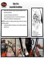
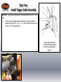
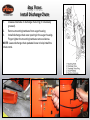
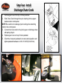
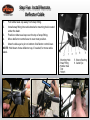
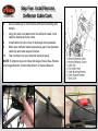
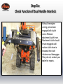
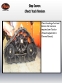
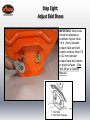
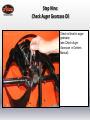
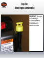
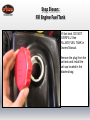
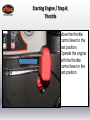
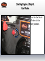
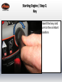
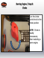
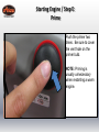
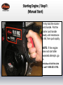
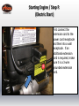
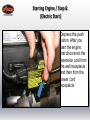
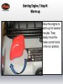
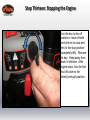
Quick Start Guide
Compact 24 LET (920020 s/n 000101 & up)
•
•
•
•
•
•
•
•
•
•
•
•
•
Step
Step
Step
Step
Step
Step
Step
Step
Step
Step
Step
Step
Step
1: Assemble Handlebar
2: Install Trigger Cable Assembly
3: Install Discharge Chute
4: Install Discharge Chute Crank
5: Install Remote Deflector Cable
6: Check Function of Dual Handle Interlock
7: Check Track Tension
8: Adjust Skid Shoes
9: Check Auger Gearcase Oil
10: Check Engine Crankcase Oil
11: Fill Engine Fuel Tank
12: Starting the Engine
13: Stopping the Engine
READ AND UNDERSTAND ALL INSTRUCTION, WARNING, AND DANGER LABELS.
IMPORTANT: READ OPERATOR’S MANUAL AND ENGINE MANUAL
THOROUGHLY AND FOLLOW THE IMPORTANT SAFE OPERATION PRACTICES
BEFORE OPERATING.
Step One:
Assemble Handlebar
1.
Remove the lower and loosen the upper hardware on the
handlebar assembly.
2.
Loosen the hardware on the shift rod.
3.
Put the speed selector lever in the sixth forward position.
4.
Rotate the handlebar into operating position.
NOTE: Be careful not to damage cable spring hooks when rotating
handlebar upward.
5.
Install and tighten the hardware on the handlebar assembly
and shift rod.
Step Two:
Install Trigger Cable Assembly
NOTICE: Trigger cable assembly comes attached to the Sno-Thro
unit.
1.
Attach remote trigger cable assembly to upper handlebar
assembly using one ¼ in x 1- ½ in oval head machine screw
and one ¼ in locking washer.
Step Three:
Install Discharge Chute
1.
Grease underside of discharge chute ring (if not already
greased).
2.
Remove mounting hardware from auger housing
3.
Install discharge chute over opening in the auger housing.
Finger tighten the mounting hardware removed above.
NOTE: Leave discharge chute pedestal loose to help install the
chute crank.
Step Four: Install
Discharge Chute Crank
1.
2.
Remove gear cover from top of chute pedestal.
Slide Chute Crank through the nylon bushing in the support
bracket under control panel.
NOTE: Be careful not to damage nylon bushing when attaching
crank to the control panel.
3. Connect the chute crank to the pinion gear on discharge chute
with spring clip pin.
4. Replace gear cover on top of chute pedestal.
5. Orient the chute and pedestal to its most vertical position and
tighten pedestal hardware to 14.8-31.0 lbf-ft (20-42 N∙m).
Step Five: Install Remote
Deflector Cable
1.
2.
Pull rubber seal cap away from snap fitting.
Install snap fitting into cable bracket’s mounting hole located
under the dash.
3.
Position rubber seal cap over the top of snap fitting.
4.
Move deflector control lever to rear most position.
5.
Attach cable eye to pin on bottom of deflector control lever.
NOTE: Hold down chute deflector cap, if needed, for more cable
slack.
Step Five: Install Remote
Deflector Cable Cont.
6.
Secure cable eye to control lever with sleeve bushing and
hairpin.
7.
Using the wire hook attached to the deflector cable, hook
cable to discharge chute crank.
8.
Install cable into clip on top of discharge chute pedestal.
9.
Make sure deflector cable loops above gear cover between
cable clip and cable support bracket.
10. Test controls to be sure deflector works properly.
NOTE: If deflector does not follow full range of travel See Remote
Discharge Deflector Control Adjustment in Owners Manual.
Step Six:
Check Function of Dual Handle Interlock
Without the engine
running, press down
(engage) both clutch
levers. Release
attachment clutch lever.
Attachment clutch should
remain engaged until
traction clutch lever is
released, then both
clutches must disengage.
If they do not, contact your
dealer for repairs.
Step Seven:
Check Track Tension
Check tracking of unit and
tension the tracks as
required (see Traction
Tension Adjustment in
Owners Manual).
Step Eight:
Adjust Skid Shoes
IMPORTANT: Skid shoes
should be adjusted as
conditions require. Allow
1/8 in. (3mm) between
scraper blade and hard
smooth surfaces. Allow 7/8
in (22 mm) between
scraper blade and uneven
or gravel surfaces. (See
Skid Shoes in Owners
Manual).
Step Nine:
Check Auger Gearcase Oil
Check oil level in auger
gearcase
(see Check Auger
Gearcase in Owners
Manual).
Step Ten:
Check Engine Crankcase Oil
IMPORTANT: The engine
is shipped with oil
in crankcase. Refer to
Engine Manual for
detailed instructions.
Step Eleven:
Fill Engine Fuel Tank
Fill fuel tank. DO NOT
OVERFILL! See
FILLING FUEL TANK in
Owners Manual.
Remove the plug from the
fuel tank and install the
fuel cap located in the
attached bag.
Step Twelve: Starting the Engine
Starting Engine / Step A:
Throttle
Move the throttle
control lever to the
fast position.
Operate the engine
with the throttle
control lever in the
fast position.
Starting Engine / Step B:
Fuel Valve
Turn the fuel shutoff valve to the
“ON” position.
Starting Engine / Step C:
Key
Insert the key and
turn to the on/start
position.
Starting Engine / Step D:
Choke
Turn the choke
control knob to the
choke position.
NOTE: Choke is
usually
unnecessary
when restarting a
warm engine.
Starting Engine / Step E:
Prime
Push the primer two
times. Be sure to cover
the vent hole on the
primer bulb.
NOTE: Priming is
usually unnecessary
when restarting a warm
engine.
Starting Engine / Step F:
(Manual Start)
Firmly hold the starter
cord handle. Pull the
starter cord handle
slowly until resistance
is felt, then pull rapidly.
NOTE: If the engine
does not start after
repeated attempts, go
to
BRIGGSandSTRATTON.COM
or call 1-800-233-3723.
Starting Engine / Step F:
(Electric Start)
First connect the
extension cord to the
power cord receptacle
and then into a wall
receptacle. If an
additional extension
cord is required, make
sure it is a 3-wire
grounded extension
cord.
Starting Engine / Step G:
(Electric Start)
Depress the push
button. After you
start the engine,
first disconnect the
extension cord from
the wall receptacle
and then from the
power cord
receptacle.
Starting Engine / Step H:
Warm up
Allow the engine to
warm up for several
minutes. Then,
slowly move the
choke control knob
to the run position.
Step Thirteen: Stopping the Engine
Turn the key to the off
position or move throttle
control lever to slow and
then to the stop position
(completely left). Remove
the key. Keep away from
reach of children. After
engine stops, turn the fuel
shut-off valve to the
closed (vertical) position.
Additional Resources
• Refer to Owners Manual and Engine Manual
• Contact Ariens Company
www.ariens.com
Phone: 920-756-4688
E-mail: [email protected]
• For issues concerning engine, please contact Briggs
and Stratton
www.BRIGGSandSTRATTON.com
Phone: 800-233-3723
2013 The Ariens Company. All rights reserved.