1
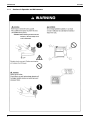
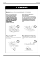
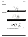
Ask a qualified installer or contractor to install this product. Do not try to install the product yourself.
Improper installation can result in water or refrigerant leakage, electrical shock, fire or explosion.
Si71 - 502
Use only those parts and accessories supplied or specified by Daikin. Ask a qualified installer or
contractor to install those parts and accessories. Use of unauthorized parts and accessories or
improper installation of parts and accessories can result in water or refrigerant leakage, electrical
shock, fire or explosion.
Read the User's Manual carefully before using this product. The User's Manual provides important
safety instructions and warnings. Be sure to follow these instructions and warnings.
Service Manual Heat Reclaim Ventilation
For any inquiries, contact your local distributor.
Heat Reclaim Ventilation
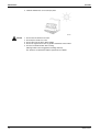
Cautions on product corrosion
1. Air conditioners should not be installed in areas where corrosive gases, such as acid gas or alkaline gas, are produced.
2. If the outdoor unit is to be installed close to the sea shore, direct exposure to the sea breeze should be avoided and choose an
outdoor unit with anti-corrosion treatment.
Dealer
Head Office:
Umeda Center Bldg., 2-4-12, Nakazaki-Nishi,
Kita-ku, Osaka, 530-8323 Japan
Tokyo Office:
JR Shinagawa East Bldg., 2-18-1, Konan,
Minato-ku, Tokyo, 108-0075 Japan
http://www.daikin.com/global/
c All rights reserved
Printed in Japan 03/2006 AK
Si71-502
The specifications, designs, and information in this brochure are subject to change without notice.
[Applied Models]
VAM 150GJVE
VAM 250GJVE
VAM 350GJVE
VAM 500GJVE
VAM 650GJVE
VAM 800GJVE
VAM1000GJVE
VAM1500GJVE
VAM2000GJVE
Si71-502
Heat Reclaim Ventilation
VAM 150GJVE
VAM 250GJVE
VAM 350GJVE
VAM 500GJVE
VAM 650GJVE
VAM 800GJVE
VAM1000GJVE
VAM1500GJVE
VAM2000GJVE
Table of Contents
i
Si71-502
1. Introduction .............................................................................................v
1.1 Safety Cautions ........................................................................................v
Part 1 General Constructions ....................................................... 1
1. General Constructions ............................................................................2
1.1 Explanation...............................................................................................2
Part 2 Product Specification ........................................................ 5
1. Product Specification ..............................................................................6
1.1 Specification .............................................................................................6
Part 3 Operation ............................................................................ 9
1. Operation ..............................................................................................10
1.1 Explanation for Systems.........................................................................10
1.2 Operation HRV Units with the Remote Control exclusively for
Air Conditioning Operation. (BRC301B61).............................................11
1.3 Operating the HRV Unit Using the Remote Controller of the
VRV-System Air Conditioner ..................................................................13
1.4 Independent operation of the HRV unit using the
Centralized controller (DCS302C(A)61) .................................................14
Part 4 Maintenance ..................................................................... 15
1. Maintenance..........................................................................................16
1.1 Maintenance for the Air Filter .................................................................16
1.2 Maintenance for the Heat Exchange Element........................................19
Part 5 Control Functions ............................................................. 21
1. Control Functions ..................................................................................22
1.1 List of Control Functions.........................................................................22
1.2 Explanation of Individual Functions........................................................23
1.3 Layout of switches on Printed Circuit Board...........................................29
Part 6 Circuit Operations ............................................................ 31
1. Circuit Operations .................................................................................32
1.1 Circuit Configuration...............................................................................32
1.2 Circuit Functions.....................................................................................33
Part 7 Troubleshooting ............................................................... 35
1. Troubleshooting ....................................................................................36
1.1
1.2
1.3
1.4
1.5
1.6
1.7
1.8
ii
Error Code Indication .............................................................................36
Overall Alarm..........................................................................................37
Overall Malfunction.................................................................................38
Indoor Air Thermistor Error.....................................................................39
Outdoor Air Thermistor Error..................................................................40
Damper System Error (Alarm)................................................................41
Damper System Error (Alarm)................................................................42
Dedicated LCD Remote Controller.........................................................43
Table of Contents
Si71-502
1.9 Data Transmission Error
(Between LCD Remote Controller and Main Unit) .................................44
1.10 Data Transmission Error (LCD Remote Controller)................................45
1.11 Data Transmission Error (Between LCD Master Remote Controller
and Slave Remote Controller) ................................................................46
1.12 Field Setting Error ..................................................................................47
1.13 Overlapping Central Control Address.....................................................48
1.14 Main Unit PCB Assembly .......................................................................49
1.15 Dedicated LCD Remote Controller.........................................................50
1.16 How to Check .........................................................................................51
1.17 Thermistor ..............................................................................................52
1.18 Power Transformer.................................................................................53
1.19 Damper Motor ........................................................................................54
Part 8 Supplementary Explanation............................................. 55
1. Supplementary Explanation ..................................................................56
1.1 Field Setting, Service Mode Operation...................................................56
Part 9 Operation Manual ............................................................. 65
1. Safety Cautions.....................................................................................68
2. What to do Before Operation ................................................................71
2.1 Names of Parts.......................................................................................71
2.2 Remote Controller and Changeover Switch:
Name and Function of Each Switch and Display ...................................73
2.3 Explanation for Systems.........................................................................76
3. Operation Procedure.............................................................................78
3.1 Independent, Combined Operation ........................................................78
3.2 Programming Start and Stop of the System with Timer .........................82
3.3 Nighttime Free Cooling Operation..........................................................84
4. Maintenance (for a Qualified Service Person Only) ..............................85
4.1
4.2
4.3
4.4
How to Clean the Air Filter .....................................................................85
Optimum Operation ................................................................................87
How to Clean the Heat Exchange Element ............................................88
Inspection of the Fan Moter....................................................................89
5. Troubleshooting ....................................................................................90
5.1 The Following Situations are not Malfunctions.......................................90
5.2 If One of the Following Malfunctions Occurs, Take the
Measures Shown Below and Contact Your Daikin Dealer .....................90
5.3 If the System does not Properly Operate Except for the above Mentioned
Case, and None of the above Mentioned Malfunctions is Evident,
Investigate the System According to the Following Procedures. ...........91
5.4 The Following Malfunctions must be Cheched by a
Qualified Service Person........................................................................92
5.5 If the System does not Properly Operate Except for the above Mentioned
Case, and None of the above Mentioned Malfunctions is Evident, Contact
Your Dealer, and Request for Investigation the System According to
the Following Procedures by a Qualified Service Person ......................92
6. After-sales Service ................................................................................93
Table of Contents
iii
Si71-502
Part 10 Appendix........................................................................... 95
1. Appendix ...............................................................................................96
1.1 Wiring Diagram.......................................................................................96
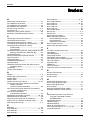
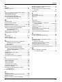
Index
............................................................................................. i
Drawings & Flow Charts ............................................................... iii
iv
Table of Contents
Si71-502
Introduction
1. Introduction
1.1
Safety Cautions
Cautions and
Warnings
Be sure to read the following safety cautions before conducting repair work.
Warning” and “
Caution”. The “
The caution items are classified into “
Warning” items
are especially important since they can lead to death or serious injury if they are not followed closely.
The “
Caution” items can also lead to serious accidents under some conditions if they are not
followed. Therefore, be sure to observe all the safety caution items described below.
About the pictograms
This symbol indicates an item for which caution must be exercised.
The pictogram shows the item to which attention must be paid.
This symbol indicates a prohibited action.
The prohibited item or action is shown inside or near the symbol.
This symbol indicates an action that must be taken, or an instruction.
The instruction is shown inside or near the symbol.
After the repair work is complete, be sure to conduct a test operation to ensure that the equipment
operates normally, and explain the cautions for operating the product to the customer.
v
Introduction
1.1.1
vi
Cautions in Operation and Maintenance
Si71-502
Si71-502
Introduction
vii
Introduction
1.1.2
Si71-502
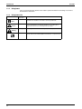
Using Icons
Icons are used to attract the attention of the reader to specific information. The meaning of each icon is
described in the table below:
1.1.3
Using Icons List
Icon
Type of
Information
Description
Note
A “note” provides information that is not indispensable, but may
nevertheless be valuable to the reader, such as tips and tricks.
Caution
A “caution” is used when there is danger that the reader, through
incorrect manipulation, may damage equipment, loose data, get an
unexpected result or has to restart (part of) a procedure.
Warning
A “warning” is used when there is danger of personal injury.
Reference
A “reference” guides the reader to other places in this binder or in this
manual, where he/she will find additional information on a specific topic.
Note:
Caution
Warning
viii
Si71-502
Part 1
General Constructions
1. General Constructions ............................................................................2
1.1 Explanation...............................................................................................2
General Constructions
1
General Constructions
Si71-502
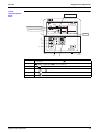
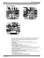
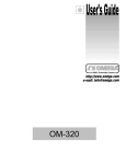
1. General Constructions
1.1
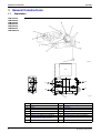
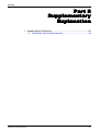
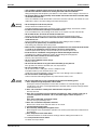
Explanation
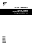
VAM150GJVE
VAM250GJVE
VAM350GJVE
VAM500GJVE
VAM650GJVE
VAM800GJVE
VAM1000GJVE
15
14
17
13
16
(HL002)
12
2
1
Hanger Bracket
2
Duct Connection Flange
3
Exhaust Fan
4
Air Filter (Long Life Filter)
5
Damper
6
Control Box
7
Maintenance Cover
8
Heat Exchange Elements
9
Name Plate
10
Air Supply Fan
11
Remote Controller (Option Accessory)
12
Damper Plate
13
EA (Exhaust Air) [Exhaust Air to Outdoor]
14
OA (Outdoor Air) [Fresh Air from Outdoor]
15
Maintenance Space for The Air Filters, Heat
Exchange Elements and Control Box
16
RA (Return Air) [Exhaust Air from Room]
17
SA (Supply Air) [Feed Air to Room]
General Constructions
Si71-502
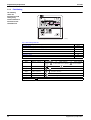
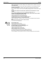
General Constructions
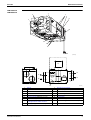
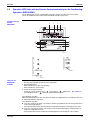
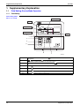
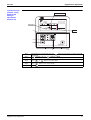
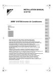
VAM1500GJVE
VAM2000GJVE
1
3
7
9
6
2
10
5
4
8
11
(HL016)
15
14
17
13
16
12
General Constructions
(HL017)
1
H Hock
2
Duct Connection Flange
3
Exhaust Fan
4
Air Filter (Long Life Filter)
5
Damper
6
Control Box
7
Maintenance Cover
8
Heat Exchange Elements
9
Name Plate
10
Air Supply Fan
11
Remote Controller (Option Accessory)
12
Damper Plate
13
EA (Exhaust Air) [Exhaust Air to Outdoor]
14
OA (Outdoor Air) [Fresh Air from Outdoor]
15
Maintenance Space for The Air Filters, Heat
Exchange Elements and Control Box
16
RA (Return Air) [Exhaust Air from Room]
17
SA (Supply Air) [Feed Air to Room]
3
General Constructions
4
Si71-502
General Constructions
Si71-502
Part 2
Product Specification
1. Product Specification ..............................................................................6
1.1 Specification .............................................................................................6
Product Specification
5
Product Specification
Si71-502
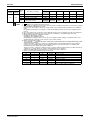
1. Product Specification
1.1
Specification
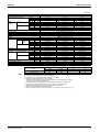
(50 / 60Hz)
Model name
Power supply
Temperature exchange efficiency
Enthalpy
exchange
efficiency
VAM150GJVE
Cooling
Heating
Casing
Insulation material
Dimensions
Heat exchange system
Heat exchange element
Air filter
Fan
Type
Air flow
rate
Ultra-High
High
Low
Ultra-High
High
Low
Ultra-High
High
Low
%
%
%
%
%
%
%
%
%
H×W×D
mm
Ultra-High
High
Low
External static pressure Ultra-High
High
Low
Fan motor
Motor output
Operating
sound
Heat
exchange
mode
Heat exchange mode
Bypass mode
Operation range (Ambient)
Connection duct diameter
Weight
Drawing number
Ultra-High
High
Low
Ultra-High
High
Low
m3 / h
m3 / h
m3 / h
Pa
Pa
Pa
Type
kW
dBA
dBA
dBA
dBA
dBA
dBA
mm
kg
VAM250GJVE
VAM350GJVE
Single phase 220 – 240 V / 220 V, 50 / 60 Hz
79 / 79
75 / 75
79 / 79
79 / 79
75 / 75
79 / 79
84 / 85
79 / 79
82 / 82
66 / 66
63 / 63
66 / 66
66 / 66
63 / 63
66 / 66
70 / 70.5
66 / 66
70 / 70
72 / 72
71 / 71
70 / 70
72 / 72
71 / 71
70 / 70
76 / 76.5
74 / 74
77 / 77
Galvanized steel plate
Self-extinguishable urethane foam
278 × 810 × 551
278 × 810 × 551
306 × 879 × 800
Air to air cross flow total heat (sensible heat + latent heat) exchange
Specially processed nonflammable paper
Multidirectional fibrous fleeces
Sirroco fan
150 / 150
250 / 250
350 / 350
150 / 150
250 / 250
350 / 350
100 / 95
155 / 155
230 / 230
120 / 154
70 / 96
169 / 222
106 / 131
54 / 65
141 / 145
56 / 60
24 / 20
67 / 30
Open type capacitor permanent split-phase induction motor, 4 poles × 2
0.030 × 2
0.030 × 2
0.090 × 2
27 – 28.5 / 28.5
27 – 29 / 29
31.5 – 33 / 33
26 – 27.5 / 27.5
26 – 27.5 / 28
30 – 31.5 / 30
20.5 – 21.5 / 21
21 – 22 / 21
23 – 25 / 23
28.5 – 29.5 / 29.5
28.5 – 30.5 / 30.5
33 – 34.5 / 34.5
27.5 – 28.5 / 28.5
27.5 – 29 / 29.5
31.5 – 33 / 31.5
22.5 – 23.5 / 22
22.5 – 23 / 22.5
24.5 – 26.5 / 24.5
–15°C to 50°CDB (80% RH or less)
φ 100
φ 150
φ 150
24
24
32
C : 4D051116
C : 4D051117
C : 4D051118
Test conditions are as follows.
Condition
Note:
1.
2.
3.
4.
5.
6.
7.
8.
6
Indoor
Outdoor
°CDB
R·H (%)
°CDB
Cooling condition
27
50
35
R·H (%)
60
Heating condition
20
40
7
70
Operation sound is measured at 1.5 m below the center of the body.
Air flow rate can be changed over to Low mode or High mode.
Normal AMP., input, efficiency depend on the other above conditions.
Operating sound is measured in an anechoic chamber.
Operating sound level generally may become greater than this value depending on the operating
conditions, reflected sound, and peripheral noise.
The sound level at the air discharge port is about 8 dB higher than the unit’s operating sound.
The specifications, designs and information here are subject to change without notice.
Temperature Exchange Efficiency is the mean value in cooling and heating.
Efficiency is measured under the following conditions.
Ratio of rated external static pressure has been kept as follows. Outdoor side to indoor side = 7 to 1
Product Specification
Si71-502
Product Specification
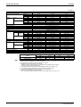
(50 / 60Hz)
Model name
Power supply
Temperature exchange efficiency
Enthalpy
exchange
efficiency
VAM500GJVE
Cooling
Heating
Casing
Insulation material
Dimensions
Heat exchange system
Heat exchange element
Air filter
Fan
Type
Air flow
rate
Ultra-High
High
Low
Ultra-High
High
Low
Ultra-High
High
Low
%
%
%
%
%
%
%
%
%
H×W×D
mm
Ultra-High
High
Low
External static pressure Ultra-High
High
Low
Fan motor
Motor output
Operating
sound
Heat
exchange
mode
Heat exchange mode
Bypass mode
Operation range (Ambient)
Connection duct diameter
Weight
Drawing number
Ultra-High
High
Low
Ultra-High
High
Low
m3 / h
m3 / h
m3 / h
Pa
Pa
Pa
Type
kW
dBA
dBA
dBA
dBA
dBA
dBA
mm
kg
VAM650GJVE
VAM800GJVE
Single phase 220 – 240 V / 220 V, 50 / 60 Hz
74 / 74
75 / 75
72 / 72
74 / 74
75 / 75
72 / 72
80 / 80.5
77 / 77.5
74 / 74.5
55 / 55
61 / 61
61 / 61
55 / 55
61 / 61
61 / 61
59 / 59.5
64 / 64.5
64 / 64.5
67 / 67
67.5 / 67.5
65 / 65
67 / 67
67.5 / 67.5
65 / 65
74 / 74.5
71.5 / 72
67.5 / 68
Galvanized steel plate
Self-extinguishable urethane foam
306 × 879 × 800
338 × 973 × 832
387 × 1,111 × 832
Air to air cross flow total heat (sensible heat + latent heat) exchange
Specially processed nonflammable paper
Multidirectional fibrous fleeces
Sirroco fan
500 / 500
650 / 650
800 / 800
500 / 500
650 / 650
800 / 800
320 / 295
500 / 470
700 / 670
105 / 150
85 / 125
133 / 170
66 / 52
53 / 67
92 / 85
32 / 18
35 / 38
72 / 61
Open type capacitor permanent split-phase induction motor, 4 poles × 2
0.090 × 2
0.140 × 2
0.280 × 2
33 – 35.5 / 34
34 – 36 / 36
39 – 40.5 / 39.5
31.5 – 34 / 32
33 – 34.5 / 34
37 – 39.5 / 37.5
25 – 28.5 / 24
27.5 – 29.5 / 28
35 – 37.5 / 34
34.5 – 36 / 35.5
35 – 37.5 / 37.5
40.5 – 42 / 41
33 – 34.5 / 33.5
33 – 35.5 / 35.5
38.5 – 40 / 39
25.5 – 28.5 / 25.5
27.5 – 30.5 / 29.5
36 – 38.5 / 35.5
–15°C to 50°CDB (80% RH or less)
φ 200
φ 200
φ 250
32
45
55
C : 4D051120
C : 4D051121
C : 4D051122
Test conditions are as follows.
Condition
Note:
1.
2.
3.
4.
5.
6.
7.
8.
Product Specification
Indoor
Outdoor
°CDB
R·H (%)
°CDB
Cooling condition
27
50
35
R·H (%)
60
Heating condition
20
40
7
70
Operation sound is measured at 1.5 m below the center of the body.
Air flow rate can be changed over to Low mode or High mode.
Normal AMP., input, efficiency depend on the other above conditions.
Operating sound is measured in an anechoic chamber.
Operating sound level generally may become greater than this value depending on the operating
conditions, reflected sound, and peripheral noise.
The sound level at the air discharge port is about 8 dB higher than the unit’s operating sound.
The specifications, designs and information here are subject to change without notice.
Temperature Exchange Efficiency is the mean value in cooling and heating.
Efficiency is measured under the following conditions.
Ratio of rated external static pressure has been kept as follows. Outdoor side to indoor side = 7 to 1
7
Product Specification
Si71-502
(50 / 60Hz)
Model name
Power supply
Temperature exchange efficiency
Enthalpy
exchange
efficiency
VAM1000GJVE
Cooling
Heating
Casing
Insulation material
Dimensions
Heat exchange system
Heat exchange element
Air filter
Fan
Type
Air flow
rate
Ultra-High
High
Low
Ultra-High
High
Low
Ultra-High
High
Low
%
%
%
%
%
%
%
%
%
H×W×D
mm
Ultra-High
High
Low
External static pressure Ultra-High
High
Low
Fan motor
Motor output
Operating
sound
Heat
exchange
mode
Heat exchange mode
Bypass mode
Operation range (Ambient)
Connection duct diameter
Weight
Drawing number
Ultra-High
High
Low
Ultra-High
High
Low
m3 / h
m3 / h
m3 / h
Pa
Pa
Pa
Type
kW
dBA
dBA
dBA
dBA
dBA
dBA
mm
kg
VAM1500GJVE
VAM2000GJVE
Single phase 220 – 240 V / 220 V, 50 / 60 Hz
78 / 78
72 / 72
77 / 77
78 / 78
72 / 72
77 / 77
80.5 / 81
75.5 / 76
79 / 81
64 / 64
61 / 61
62 / 62
64 / 64
61 / 61
62 / 62
68.5 / 69
64 / 64.5
66 / 67
70 / 70
65 / 65
72 / 72
70 / 70
65 / 65
72 / 72
72.5 / 73
67 / 67.5
75 / 76
Galvanized steel plate
Self-extinguishable urethane foam
387 × 1,111× 1,214
785 × 1,619 × 832
785 × 1,619 × 1,214
Air to air cross flow total heat (sensible heat + latent heat) exchange
Specially processed nonflammable paper
Multidirectional fibrous fleeces
Sirroco fan
1,000 / 1,000
1,500 / 1,500
2,000 / 2,000
1,000 / 1,000
1,500 / 1,500
2,000 / 2,000
860 / 840
1,320 / 1,260
1,720 / 1,580
168 / 192
112 / 150
116 / 140
110 / 86
73 / 72
58 / 32
85 / 60
56 / 50
45 / 45
Open type capacitor permanent split-phase induction motor, 4 poles × 2
0.280 × 2
0.280 × 4
0.280 × 4
39.5 – 41.5 / 39.5
39.5 – 41.5 / 41.5
41.5 – 43.5 / 42
37.5 – 39.5 / 37.5
37.5 – 39.5 / 39.5
39 – 43 / 40
35 – 37.5 / 34.5
35 – 37.5 / 36
36 – 39 / 39
40.5 – 42.5 / 40.5
41 – 43 / 42.5
43 – 45.5 / 44
38.5 – 40.5 / 38.5
39.5 – 41 / 41.5
40.5 – 45 / 42
36 – 38.5 / 35.5
36.5 – 38 / 37.5
37.5 – 39.5 / 41
–15°C to 50°CDB (80% RH or less)
φ 250
φ 350
φ 350
67
129
157
C : 4D051123
C : 4D051119
C : 4D051124
Test conditions are as follows.
Condition
Note:
1.
2.
3.
4.
5.
6.
7.
8.
8
Indoor
Outdoor
°CDB
R·H (%)
°CDB
Cooling condition
27
50
35
R·H (%)
60
Heating condition
20
40
7
70
Operation sound is measured at 1.5 m below the center of the body.
Air flow rate can be changed over to Low mode or High mode.
Normal AMP., input, efficiency depend on the other above conditions.
Operating sound is measured in an anechoic chamber.
Operating sound level generally may become greater than this value depending on the operating
conditions, reflected sound, and peripheral noise.
The sound level at the air discharge port is about 8 dB higher than the unit’s operating sound.
The specifications, designs and information here are subject to change without notice.
Temperature Exchange Efficiency is the mean value in cooling and heating.
Efficiency is measured under the following conditions.
Ratio of rated external static pressure has been kept as follows. Outdoor side to indoor side = 7 to 1
Product Specification
Si71-502
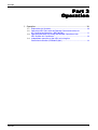
Part 3
Operation
1. Operation ..............................................................................................10
1.1 Explanation for Systems.........................................................................10
1.2 Operation HRV Units with the Remote Control exclusively for
Air Conditioning Operation. (BRC301B61).............................................11
1.3 Operating the HRV Unit Using the Remote Controller of the
VRV-System Air Conditioner ..................................................................13
1.4 Independent operation of the HRV unit using the
Centralized controller (DCS302C(A)61) .................................................14
Operation
9
Operation
Si71-502
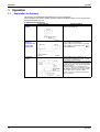
1. Operation
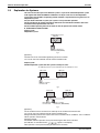
1.1
Explanation for Systems
This product is operated differently depending on the system configuration.
For the operation of the remote controller for indoor unit and centralized controller, refer to the instruction
manual provided with each unit.
Operation for Each System
System Example
Operation Method
Independent
System
The remote controller turns on and off the air
conditioner and HRV unit.
Combined
Operation
System with VRV
Systems and
Skyair Series
The remote controller for VRV turns on and off
the air conditioner and HRV unit.
If only the HRV unit is used without operating
”
the air conditioner, set the unit in the “
VENTILATION mode.
Centralized
System
When the HRV remote controllers is not
connected, the Centralized controller controls
the operation of the HRV unit.
When the HRV remote controllers is connected,
operation can be started and stopped using the
Centralized controller or the indoor and the HRV
remote controllers.
During the indication of centralized control
” appears on the display, the ON/
“
OFF and timer operation may not be possible
with the HRV remote controllers. Other
operations can be performed using the HRV
remote controllers.
10
Operation
Si71-502
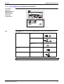
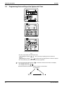
1.2
Operation
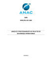
Operation HRV Units with the Remote Control exclusively for Air Conditioning
Operation. (BRC301B61)
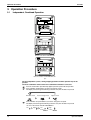
For non-independent systems, starting/stopping operation and timer operation may not be possible.
Use the air conditioner remote control or the Centralized controller in such cases.
Remote Controller
for HRV
BRC301B61
5
7
1
2
6
8
11
12
13
4
10
9
3
(HL006)
Operation for
INDIVIDUAL
SYSTEM
1. Operation lamp
This pilot lamp (red) light up while the unit is in Operation.
2. Operation/Stop button
When pushed once, the unit starts operating.
When pushed twice, the unit stops.
3. Air flow rate changeover button
Air flow rate can be changed over to “
” [Low] mode or “
” [High] mode, “
[Low FRESH UP] mode, “
FRESH UP” [High FRESH UP] mode.
FRESH UP”
For “FRESH UP” operation
When this indication does not show: The volume of outdoor air supplied into the room and that of the room
air exhausted outdoors is equivalent.
For “FRESH UP” operation,
If it is set to “Fresh up air supply”: The volume of outdoor air supplied into the room is larger than that of
room air exhausted outdoors.
(This operation prevents the odor and moisture from kitchens and toilets from flowing into the rooms.
If it is set to “Fresh up air exhaust”: The volume of room air exhausted outdoors is larger than that of
outdoor air supplied into the room.
(This operation prevents the hospital odor and floating bacteria from flowing out to the corridors.)
Operation
11
Operation
Si71-502
4. Ventilation mode changeover: button
“
” (Automatic) mode ...... The temperature sensor of the unit automatically changes the
ventilation of the unit in [Bypass] mode and [Heat Exchange] mode.
“
” (Heat Exchange) mode ...... In this mode, the air passes through the heat exchange element
to effect [Total Heat Exchanging] ventilation.
“
” (Bypass) mode ...... In this mode, the air does not pass through the heat exchange element
but bypasses it to effect [Bypass] ventilation.
5. Indication of operation control method:
When the operation of HRVs are linked with the air conditioners, this indication may be shown. While
the indication is shown, the ON/OFF of HRVs cannot be operated by the HRV remote controller.
6. Indication of operation standby:
It indicates the precooling/preheating operation. This unit is at stop and will start operation after the
precooling/preheating operation is over.
Precooling/preheating operation means the operation of HRVs is delayed during the startup operation
of linked air conditioners such as before the office hours. During this period the cooling or heating load
is reduced to bring the room temperature to the set temperature in a short time.
7. Indication of centralized control:
When a remote controller for air conditioners or devices for centralized control are connected to the
HRVs, this indication may show.
During this indication appears on the display, the ON/OFF and timer operation may not be possible with
the HRV remote controllers.
8. Indication of air filter cleaning
When the indication “
” appears on the display, clean the filter.
9. Filter signal reset button
10.Inspection button
This button is to be used only for service. It is not to be used normally.
HOW TO OPERATE WITH TIMER
11.Push the button “
” and select either one of “
” or “
Each time the button is pushed, the indication changes as shown below.
”.
12.Push the button “
” and set the time.
Each time when “
” is pushed, the time advances one hour.
Each time when “
” is pushed, the time goes back one hour.
13.Push the button “
”.
Then, the reservation is finished.
Either “
” or “
” changes from flashing to lighting.
After the reservation is finished, the remaining time is indicated in the display.
For cancelling the timer operation, push the button “
” once again.
The indication disappears.
12
Operation
Si71-502
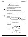
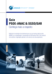
1.3
Operation
Operating the HRV Unit Using the Remote Controller of the VRV-System Air
Conditioner
Remote Controller
for VRV
BRC1C51·61
1. Operation lamp
2. Operation/stop button
3. Air flow rate changeover button
4. Ventilation mode changeover button
5. Indication of air flow rate
6. Indication of operation control method
7. Indication of centralized control
8. indication of air filter cleaning
9. Filter signal reset button
10.Inspection button
11.Push the button “
” and select either one of “
” or “
Each time the button is pushed, the indication changes as shown below.
”.
12.Push the button “
” and set the time.
Each time when “
” is pushed, the time advances one hour.
Each time when “
” is pushed, the time goes back one hour.
13.Push the button “
”
Then, the reservation is finished.
Either “
” or “
” changes from flashing to lighting.
After the reservation is finished, the remaining time is indicated in the display.
For cancelling the timer operation, push the button “
” once again.
The indication disappears.
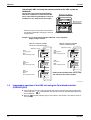
14.If you press these buttons when using independent operation of the HRV unit, the message “Not
Available” will appear on the display for a few seconds.
When the VRV-system air conditioner is connected with the HRV unit with a direct duct, the remote
controller of the air conditioner cannot be used to select the VENTILATION mode. To use the HRV unit
without operating the air conditioner, set the air conditioner in the FAN VENTILATION mode and select
the low fan speed.
Operation
13
Operation
Si71-502
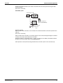
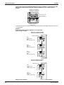
Operating the HRV unit using the remote controller of the VRV- system air
conditioner
The HRV unit cannot be operated independently
when the air conditioner is connected to the HRV
unit via a duct. When using the HRV unit, set the air
conditioner to “fan” mode on weak fan strength.
Operation mode display
“Ventilation” is displayed.
Operation mode
selector button
hr
hr
TEST
NOT
AVAILABLE
TEST
•
Each time you press the operation selection button,
the operation mode display will change as shown in
the figure below.
Remote controller for indoor unit
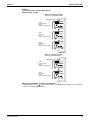
Example 1: In case of the remote controller “BRC1C61” and as equivalent.
Display changes as below.
When air conditioner and HRV
unit are not connected via duct
<Operation mode>
When air conditioner and HRV
unit are connected via duct
<Operation mode>
VRV:
Cooling mode
HRV:
Heat exchange mode
VRV:
Cooling mode
HRV:
Heat exchange mode
VRV:
Fan mode
HRV:
Heat exchange mode
VRV:
Fan mode
HRV:
Heat exchange mode
VRV:
Stopping
HRV:
Heat exchange mode
NOTE) Current Ventilation mode can be visible
and selected on the remote controller.
3P034927-5K
1.4
Independent operation of the HRV unit using the Centralized controller
(DCS302C(A)61)
After selecting the zone where the only the HRV unit operation is desired, press the operation mode
selector and select “
” VENTILATION. The HRV unit can then be operated independently from
the air conditioner.
“FILTER” indication appears on the display, clean the filter of the HRV unit. (Refer to
When the
the section 3.)
14
Operation
Si71-502
Part 4
Maintenance
1. Maintenance..........................................................................................16
1.1 Maintenance for the Air Filter .................................................................16
1.2 Maintenance for the Heat Exchange Element........................................19
Maintenance
15
Maintenance
Si71-502
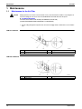
1. Maintenance
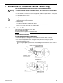
1.1
Maintenance for the Air Filter
Caution
During operation, never check or clean the HRV. It may cause electrical shock and it is very dangerous to
touch the rotating part. Be sure to turn off the OPERATION switch and disconnect the power.
CLEANING FREQUENCY
AT LEAST ONCE EVERY TWO YEARS (FOR GENERAL OFFICE USE)
(CLEAN THE ELEMENT MORE FREQUENTLY IF NECESSARY.)
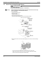
1. Go into ceiling through the inspection hole, remove the hanging metals of maintenance cover and take
it off.
VAM150~1000GJVE
1
Maintenance Cover
3
Hanging Metal
1
Maintenance Cover
3
Hanging Metal
2
Binding Metal
2
Binding Metal
VAM1500~2000GJVE
16
Maintenance
Si71-502
Maintenance
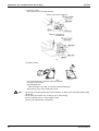
2. Take out the heat exchange elements from the unit body.
VAM150~1000GJVE
1
Heat Exchange Element (X2)
2
Handle
3
Rail
4
Air Filter × 2
1
Heat Exchange Element (X4)
2
Handle
3
Rail
4
Air Filter × 4
VAM1500~2000GJVE
3. To clean the air filter, lightly pat it with hand or remove dust with a vacuum cleaner. If excessively dirty,
wash it in water.
4. If the air filter is washed, remove water completely and allow to dry Air filter for 20 to 30 minutes in the
shade. When dried completely, install the air filter back in place.
Maintenance
17
Maintenance
Si71-502
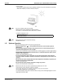
5. Install the maintenance cover securely in place.
Caution
18
1.
2.
3.
4.
5.
Do not wash the air filter in hot water.
Do not dry the air filter over a fire.
Do not expose the air filter to direct sunlight.
Do not use organic solvent such as gasoline and thinner on the air filter.
Be sure to install the air filter after servicing.
(Missing air filter causes clogged heat exchange element.)
The air filter is an optional item and the replacement is available.
Maintenance
Si71-502
1.2
Maintenance
Maintenance for the Heat Exchange Element
CLEANING FREQUENCY
AT LEAST ONCE EVERY TWO YEARS (FOR GENERAL OFFICE USE)
(CLEAN THE ELEMENT MORE FREQUENTLY IF NECESSARY.)
1. Use a vacuum cleaner to remove dust and foreign objects on the surface of the heat exchange element.
Use the vacuum cleaner equipped with a brush on the tip of the suction nozzle.
Lightly contact the brush on the surface of the heat exchanging element when cleaning. (Do not crush
the heat exchange element while cleaning.)
2. Install the air filter securely in place.
3. Put the heat exchange element on the rail and insert it securely in place.
4. Install the maintenance cover securely in place.
Caution
Maintenance
Never wash the heat exchanger element with water.
19
Maintenance
20
Si71-502
Maintenance
Si71-502
Part 5
Control Functions
1. Control Functions ..................................................................................22
1.1 List of Control Functions.........................................................................22
1.2 Explanation of Individual Functions........................................................23
1.3 Layout of switches on Printed Circuit Board...........................................29
Control Functions
21
Control Functions
Si71-502
1. Control Functions
1.1
List of Control Functions
Classification
1. Basic functions
(functions related to
basic performance)
Function name
Outline of function
1.1 Ventilation
operation control
function
Controls supply air fan motor, exhaust air fan motor and damper
motor.
1.2 Abnormality
control function
Detects abnormalities in thermistor, damper motor and data
transmission to prevent errors.
2. Additional functions 2.1 Ventilation mode
changeover function
Operates equipment in selected ventilation mode (total heat
exchange, normal, automatic).
2.2 Automatic
ventilation operation
function
Selects the most suitable ventilation mode by controlling damper
motor according to temperature controller mode, temperature
setting and thermistor data.
2.3 Ventilation
capacity changeover
function
Operates equipment at set airflow rate.
2.4 Humidifier
operation control
function
Controls humidifier output based on temperature controller
judgment. Note 1
2.5 Pre-cool/pre-heat Prevents equipment operation for a preset time (set time) after
function
air conditioner is turned on.
2.6 Fresh-up function
Sets motor tap so that supply air fan airflow rate is larger than
exhaust air fan airflow rate.
2.7 Filter sign function Stores cumulative operation hour data and turns on air filter
cleaning indicator.
3. System control
functions
3.1 Remote controller Operates equipment according to instructions from remote
function
controller.
3.2 Group function
Operates two or more units based on instructions from single
remote controller.
3.3 Air conditioner link Follows air conditioner ON/OFF instructions.
function
4. Other support
functions
Note:
22
3.4 Power ON
operation function
Operates equipment when power is turned on.
3.5 External link
operation function
Turns equipment on and off according to external link terminal
signal (no-voltage contact a).
3.6 Centralized
control function
Allows remote control operation by centralized control
equipment.
3.7 Timer function
Turns equipment on and off at set time.
4.1 Troubleshooting
function
Displays error codes to indicate locations of error.
4.2 Field setting
function
Allows initial setting from LCD remote controller.
Note 1
Requires optional humidifier and optional printed circuit board (KRP50-2 : Wiring adapter for remote
contact).
Control Functions
Si71-502
Control Functions
1.2
Explanation of Individual Functions
1.2.1
Ventilation Operation Control
Controls ventilation fan motors (supply and exhaust air fans) and damper motor.
1) Normal operation
Operation chart
Remote controller
indication
Heat reclaim
ventilation unit
Cleaning
Operation time
Ventilation fan motor
Damper motor
(ventilation mode)
Operation lamp
Filter sign
reset
Stop
Normal ventilation
mode selection
ON
OFF
ON
Total heat exchange
ventilation
ON
Normal ventilation
Total heat
exchange
ventilation
ON
ON
Filter sign indicator
(HL020)
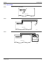
2) Direct duct connection with air conditioner
Operation chart
Air conditioner
Operation
ON/OFF
Operation
Fan motor
ON
Normal ventilation
mode selection
Air conditioner
fan OFF
Air conditioner
fan ON
Remote controller
indication
Heat reclaim
ventilation unit
OFF
Ventilation fan motor
Damper motor
(ventilation mode)
ON
Total heat
exchange
ventilation
OFF
ON Normal
ventilation
OFF
Total heat
exchange
ventilation
10 sec
ON
Normal ventilation
Operation lamp
Lamp
ON
(HL021)
Note:
Control Functions
Direct duct connection setting can be made in VRV system or using field setting mode of HRV LCD remote
controller.
23
Control Functions
1.2.2
Si71-502
Pre-cool/Pre-heat
Pre-cool/pre-heat operations require the following conditions.
1. System
Pre-heat operation is possible only in air conditioner linked system (1 group, 2-group link). Check the
system first.
2. Heat reclaim ventilation setting
Set Pre-heat ON/OFF to ON.
Pre-cool/pre-heat On/OFF setting can be made in air conditioner or using field setting mode of LCD
remote controller of heat reclaim ventilation unit. (Pre-cool time can be set between 30 and 60 min, and
pre-heat time can be set between 30 and 150 min.)
3. Others
a) Heat reclaim ventilation unit must be in non-operating condition for two consecutive hours or more
prior to pre-cool/pre-heat operation.
b) Temperature control mode of the air conditioner must be set to Cool, Heat or Dry.
Heat reclaim
ventilation unit
Air conditioner
Operation
Normal ventilation Pre-cool/pre-heat
mode selection
time over
ON/OFF
Operation
OFF
Ventilation fan motor
ON
Pre-cool/pre-heat ventilation
Damper motor
(ventilation mode)
Total heat exchange ventilation
Remote controller
indication
Stop
Operation lamp
Lamp
ON
Operation standby
indication
Lamp
ON
ON
Normal ventilation
Total heat
exchange
ventilation
(HL022)
Note:
24
Operation standby indication is displayed only on LCD remote controller of heat reclaim ventilation unit.
Control Functions
Si71-502
1.2.3
Control Functions
Cold Area Mode
Stops or lowers ventilation airflow during defrosting operation and compressor non-operating condition
when equipment in heating mode, thus reducing heating load and cold air draft.
Operation chart (in heating operation only)
Air conditioner
Operation
ON/OFF
Operation
Fan motor
ON
Normal ventilation
mode selection
Defrosting operation
or compressor in
Non-defrosting operation or
non-operation
compressor in operation
OFF
Remote controller
indication
Heat reclaim
ventilation unit
10 sec
Ventilation fan motor
ON
OFF
ON
OFF
ON
OFF or lower
Damper motor
(ventilation mode)
Total heat
exchange
ventilation
ON Normal
ventilation
Total heat
exchange
ventilation
ON
Normal ventilation
Operation lamp
Lamp
ON
(HL023)
Note:
Cold area mode can set using remote controller for air conditioner or field setting mode of LCD remoter
controller of heat reclaim ventilation unit.
Protection Control
Operation Control in Cold Climates
To operate the unit at low outdoor temperatures, control the air supply fans and the exhaust fans as shown
below for equipment protection.
Normal operation
Models applicable to outdoor
temperatures of -15˚C at minimum
Outdoor temperature<-10°C
Outdoor temperature>-8°C
Air supply fan
ON for 45 min., OFF for 15 min.
Outdoor temperature<-15°C
Outdoor temperature>-13°C
Air supply fan stop (*)
Exhaust fan stop (*)
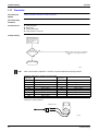
1.2.4
Air Conditioner Link Operation
Link system enables simultaneous ON/OFF operation of heat reclaim ventilation unit and air conditioner
(VRV system, Skyair).
1) 1 group link control
Allows simultaneous ON/OFF from remote controller for air conditioner.
Allows independent operation of heat reclaim ventilation unit from VRV-system remote controller during
interim periods (not possible when direct duct connection is used).
VRV system
Remote
controller for
air conditioner
(HL024)
Control Functions
25
Control Functions
Si71-502
2) Link control of 2 or more groups (zone link)
Heat reclaim ventilation unit can be operated when one or more air conditioners are operating.
Allows independent operation of heat reclaim ventilation unit from VRV-system remote controller during
interim periods (direct duct connection is not allowed in this system).
Group
1
Group
2
Group
3
Remote controller Remote controller Remote controller
for air conditioner for air conditioner for air conditioner
Adapter PCB
for remote control
(KPR2A61)
Note:
1.2.5
(HL025)
With Super Wiring, units of different outdoor systems can be linked in operation.
Field Setting, Service Mode
1. Field setting
Used for initial setting of heat reclaim ventilation unit.
2. Service mode
Used for confirmation of unit Nos. in the group and reallocation of unit Nos.
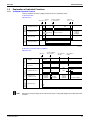
List of Field Setting and Service Mode
List of Settings
Mode No.
Group
settings
17
Individual
settings
Setting
switch
No.
26
02
03
04
05
06
Approx.
2500
hours
Approx.
1250
hours
No
counting
–
–
–
Filter cleaning time setting
1
Nighttime free cooling operation
start time (after other air
conditioners operating together
with the unit have been stopped)
Off
2 hours
4 hours
6 hours
8 hours
–
2
Pre-cool/pre-heat on/off setting
Off
On
–
–
–
–
3
Pre-cool/pre-heat time setting
30 min
45 min
60 min
–
–
–
4
Fan speed initial setting
Normal
Ultra high
–
–
–
–
Yes/No setting for direct duct
connection with VRV system
No duct
(Air flow
setting)
With duct
(fan off)
–
–
–
–
Setting for cold areas (Fan
operation selection for heater
thermo OFF)
–
–
Fan off
Fan L
Fan off
Fan L
High
Ultra high
–
–
–
–
Centralize
d
Individual
–
–
–
–
27
28
01
0
5
18
Setting position No. (NOTE 1)
Description of Setting
6
Nighttime free cooling operation
air flow setting
7
Centralized/individual setting
8
Centralized zone interlock setting
9
Pre-heat time extension setting
0
External signal JC/J2
No duct
With duct
No
Yes
–
–
–
–
0 min
30 min
60 min
90 min
–
–
Last
command
Priority on
external
input
Priority on
operation
–
–
–
–
1
Setting for direct Power ON
Off
On
–
–
–
2
Auto restart setting
Off
On
–
–
–
–
3
External damper operation
–
–
On
–
–
–
4
Indication of ventilation mode/Not
indication
Indication
No
Indication
–
–
–
–
7
Fresh up air supply/exhaust
setting
No
Indication
No
Indication
Indication
Indication
–
–
Supply
Exhaust
Supply
Exhaust
–
8
External input terminal function
selection (between J1 and JC)
Fresh-up
Overall
alarm
Overall
malfunction
9
KRP50-2 output switching
selection (between 1 and 3)
Humidifying
on/off
Abnormal
–
Fan forced
Forced off
off
–
–
–
Air flow
increase
–
Control Functions
Si71-502
Control Functions
Mode No.
Group
settings
19
Individual
settings
Setting
switch
No.
29
Note:
Setting position No. (NOTE 1)
Description of Setting
01
02
03
04
05
06
High
0
Ventilation air flow setting
Low
Low
Low
Low
High
2
Ventilation mode setting
Automatic
Exchange
By pass
–
–
–
3
“Fresh Up” on/off setting
Off
On
–
–
–
–
8
Electric heater setting
No delay
Exchange
On, off
delay
On, off
delay
–
–
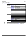
1.
indicates the setting position at the factory.
2. The settings are applied to the entire group, but if the mode no. inside the parentheses is selected, the settings
can be applied to individual indoor units.
However, it is only possible to check any changes made to the settings inside the parentheses in individual
mode.
(For group batch operation, the changes are made but the display remains as it was when shipped from the
factory.)
3. Do not set anything not shown above. If the applicable functions are not available, they will not be displayed.
4. When returning to normal mode, the remote controller is initialized, so the display might show “88.”
5. Group number setting for centralized controller
(1) Mode No. 00 : Group controller
(2) Mode No. 30 : Individual controller
* Regarding the setting procedure, refer to the section “Group number setting for centralized control” in the
operating manual of either the on/off controller or the central controller.
6. Details of external input setting
“Last command”........... Only when HRV units are in independent operation. External input is not available with interlocked operation
of HRV units and air conditioners.
“Priority on external input” ... Remote controllers are available while the external input terminal is closed. Remote
controllers are not available while the external input terminal is open. External input is not available with
interlocked operation of HRV units and air conditioners.
“Priority on operation” ... Either air conditioner remote controllers with interlocked operation of HRV units and air
conditioners, or external input is in operation, when HRV units are in operation.
Setting is available with interlocked operation of HRV units and air conditioners.
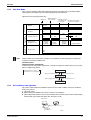
7. Details of external input terminal function are as follows:
Setting position
Input contact
Fan operation
Operation lamp
01
a
ON
Turn ON
02
a
ON
Turn ON
Malfunction code indicates “60”
03
a
OFF
Blinking
Malfunction code indicates “60”
04
b
OFF
Turn OFF
Automatic reset OFF
05
b
OFF
Turn ON
Automatic reset ON
06
a
ON
Turn ON
Air flow rate increases (Low→High, High→Ultra high)
Fresh up operation
* Setting position “04” does not function with interlocked operation of HRVs and air conditioners.
C : 3P034928-5J
Control Functions
27
Control Functions
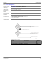
1.2.6
Si71-502
External Damper Operation (FIELD SUPPLY)
Explanation of
Functions
Intake of outdoor air can be prevented when HRV is switched OFF if this damper is incorporated in the
system.
1. The total heat exchanger’s main unit print board supplies power for external damper.
Essential Wiring
1. Connect one end of the harness to the X15A on the print board and the other end to the harness
leading to the damper via a connector such as a closed connector.
With regard to closed connector, select one that suits wire diameter.
Essential Setting
Changes
28
The X15A output is at the default setting and is not in operation, so the output setting should be changed at
the LCD of the remote controller.
Setting changes should be made in the following way.
Mode No.: 18 (group tie up) or 28 (per each unit)
Setting switch No.: 3
Setting position No.: 03
Control Functions
Si71-502
Control Functions
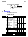
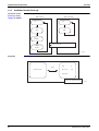
1.3
Layout of switches on Printed Circuit Board
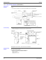
1.3.1
Printed Circuit Board
Layout of switches on printed circuit board
<In case of VAM 150 ~ 1000GJVE>
1.
2.
3.
4.
5.
Transformer
Secondary
Primary
Connector for supply air fan
Connector for exhaust air fan
Control Functions
6. Connector for damper
7. Power supply
8. Terminals
9. Connector for KPR50-2
10.Connector for damper
<In case of VAM 1500 · 2000GJVE>
11.Connector for indoor air
thermistor
12.Connector for outdoor air
thermistor
13.Selector switch
14.Terminal port for remote
controller
15.Terminal port for centralized
control
16.Terminal port for no-voltage
external input
17.Factory setting
3P034928-5J
29
Control Functions
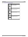
1.3.2
Si71-502
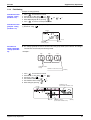
Function of main connection terminal
Input from outside
Centralized control
Remote controller
Power supply
Terminal No.
Contents of function
Single phase 220 – 240 V 50Hz
Single phase 220 – 220 V 60Hz
Power supply and earth terminal
L N
TeS1
P1 P2
Connection terminal for remote controller for HRV
unit.
This terminal is used to receive information of the
indoor unit for interlocked operation.
This terminal is used to receive information when
centralized controller is connected.
F1 F2
J1 J2 JC
Between terminal no. (J1) ~ (JC)
Used for “fresh up operation” by external input.
Between terminal no. (J2) ~ (JC)
Used for Operation / Stop by external input.
(HC0043)
30
Control Functions
Si71-502
Part 6
Circuit Operations
1. Circuit Operations .................................................................................32
1.1 Circuit Configuration...............................................................................32
1.2 Circuit Functions.....................................................................................33
Circuit Operations
31
Circuit Operations
Si71-502
1. Circuit Operations
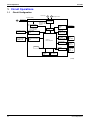
1.1
Circuit Configuration
Fan motor
FM
DM
Damper motor
PCB assembly
Transformer
+16V Power supply
+ 5V circuit
To circuits and
microcomputer
Centralized control
equipment
Central data
transmission interface
circuit
Remote controller
for heat reclaim
ventilation unit
Remote control signal
transmission interface
circuit
Detection and
cut-off of+16V
current
Fan motor,
damper
motor relay
Relay drive
circuit
Thermistor
interface
circuit
Thermistor
Airflow rate
setting switch
interface circuit
Damper motor
limit switch
interface circuit
Damper
motor
limit switch
External input
interface circuit
Air
conditioner
of other
maker, etc.
Control
microcomputer
EEPROM
KRP50-2
interface circuit
Humidifier,
abnormality
signal
output, etc.
Microcomputer Microcomputer
oscillation
reset circuit
circuit
(HL026)
32
Circuit Operations
Si71-502
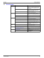
1.2
Circuit Operations
Circuit Functions
Classification
Input/output
Function
Used by centralized control equipment for
operation control. Allows control of up to 64
groups of air conditioners and heat reclaim
ventilation units. Use of KRP2A61 allows zone
link operation.
Remote control data transmission interface
Use of dedicated LCD remote controller allows
control of up to 16 heat reclaim ventilation
units. Also used for linked operation of air
conditioners of 2 groups.
Air conditioner link operation
Connects to remote control line of air
conditioner for linked operation.
KRP50-2 interface
Can be used to output signals of operating
condition and abnormalities to external
equipment or to connect humidifier via KRP502.
Relay drive circuit
Supplies drive voltage to relay coils.
Fan motor, damper motor relay
Power supply relay for fan motor and damper
motor.
Thermistor interface
Uses thermistor (temperature sensor) to detect
inside and outside temperatures.
Airflow rate setting switch interface
Used to set airflow rate of main unit when
dedicated remote controller is not used.
External input interface
Used to control main unit with external contact
point. (Fresh-up, external link operation, etc.)
Damper limit switch interface
Sends signal of limit switch condition to
microcomputer for damper motor cam
positioning.
Control microcomputer
Controls entire equipment by varying output
according to input condition.
EEPROM
Stores operating condition and address data.
Microcomputer Microcomputer reset circuit
Resets microcomputer when power is turned
on.
Output
Input
Peripheral
Parts
Power Supply
Circuit Operations
Circuit
Central data transmission interface
Microcomputer oscillation circuit
Generates clock frequency for microcomputer
operation.
Power transformer
Produces power supply of approx. 26 VAC
from 220-240 VAC.
Power supply circuit
Supplies direct currents (16 VDC, 5 VDC) to
control circuits.
33
Circuit Operations
34
Si71-502
Circuit Operations
Si71-502
Part 7
Troubleshooting
1. Troubleshooting ....................................................................................36
1.1
1.2
1.3
1.4
1.5
1.6
1.7
1.8
1.9
1.10
1.11
1.12
1.13
1.14
1.15
1.16
1.17
1.18
1.19
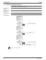
Troubleshooting
Error Code Indication .............................................................................36
Overall Alarm..........................................................................................37
Overall Malfunction.................................................................................38
Indoor Air Thermistor Error.....................................................................39
Outdoor Air Thermistor Error..................................................................40
Damper System Error (Alarm)................................................................41
Damper System Error (Alarm)................................................................42
Dedicated LCD Remote Controller.........................................................43
Data Transmission Error
(Between LCD Remote Controller and Main Unit) .................................44
Data Transmission Error (LCD Remote Controller)................................45
Data Transmission Error (Between LCD Master Remote Controller
and Slave Remote Controller) ................................................................46
Field Setting Error ..................................................................................47
Overlapping Central Control Address.....................................................48
Main Unit PCB Assembly .......................................................................49
Dedicated LCD Remote Controller.........................................................50
How to Check .........................................................................................51
Thermistor ..............................................................................................52
Power Transformer.................................................................................53
Damper Motor ........................................................................................54
35
Troubleshooting
Si71-502
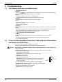
1. Troubleshooting
1.1
Error Code Indication
When an abnormality is generated, take necessary measures by referring to displayed error code.
After the cause of abnormality is removed, operate equipment and check proper functioning.
Operation lamp
(LED)
Inspection indication
Indication of unit No. of abnormal
heat reclaim ventilation unit
Error code
(HL027)
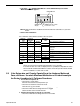
List of malfunction codes displayed by LCD remote controller
LCD Remote Controller Display
Error Code Operation
LED
Inspection
Indication
Description of Abnormality
Unit No.
Page
ON
OFF
Blinking
Overall alarm
P37
Blinking
Blinking
Blinking
Overall malfunction
P38
64
ON
OFF
Blinking
Inside air thermistor error
P39
65
ON
OFF
Blinking
Outside air thermistor error
P40
6A
ON
OFF
Blinking
Damper system alarm
P41
6A
Blinking
Blinking
Blinking
Damper system + thermistor error
P42
U5
Blinking
Blinking
Blinking
Data transmission error between LCD remote
controller and main unit
P44
60
U5
OFF
Blinking
OFF
LCD remote controller connection error
P45
U8
OFF
Blinking
OFF
Data transmission error between master-slave
LCD remote controllers
P46
UA
OFF
Blinking
OFF
LCD remote controller connection error (no
remote controller for air conditioner in air
conditioner group)
P47
Overlapping central control address
P48
Transmission error between the unit and
centralized controller
—
UC
ON
ON
ON
UE
Blinking
Blinking
Blinking
In case of the malfunction with the shaded error code, the unit still operates. However, be sure to have it
inspected and repaired and as soon as possible.
Main Unit PCB
CN1
CN2
CN3
CN4
CN7
Exhaust
air fan
CN10 CN11 CN5 CN6 CN12
CN13
Supply
air fan
CN8
N
FuL 10A
L
KRP
50-2
CN9
LED A
(Microcomputor Operation Monitor)
P2
P1
F1
F2
J1
J2
JC
(HL031)
36
Troubleshooting
Si71-502
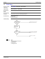
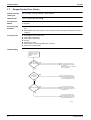
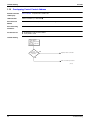
1.2
Troubleshooting
Overall Alarm
60
Remote Controller
LCD Display
Error Code
LED Indication
Remote Controller 4
Error Detection
Method
Abnormalities are detected based on external input terminals (J1-JC).
Error Generating
Conditions
When external input terminal (J1-JC) short-circuit during operation
(“Overall Alarm” must be set in field setting mode Note 1).
Possible Causes
Faulty external device
Broken wire
Faulty control PCB
Inspection OFF Unit No. Blinking
Main Unit 5
Troubleshooting
Is
connected
external device
operating
properly?
NO
Remove the cause of error in
connected external device.
YES
Measure resistance
between external
input terminals
(J1-JC).
Is
resistance
200 Ω or
lower?
NO
Check wires for abnormalities
(broken wire, faulty contact,
etc.).
YES
Replace control PCB.
(HF001)
Note:
Note 1:
Refer the field setting mode page 26
Setting mode 18
Setting switch 8
Setting position 02
{
Troubleshooting
37
Troubleshooting
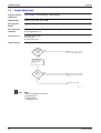
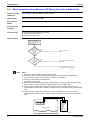
1.3
Si71-502
Overall Malfunction
60
Remote Controller
LCD Display
Error Code
LED Indication
Remote Controller 5 Main Unit 5
Error Detection
Method
Abnormalities are detected based on external input terminals (J1-JC).
Error Generating
Conditions
When external input terminal (J1-JC) short-circuit during operation (“Overall Malfunction” must be set in
field setting mode Note 2.).
Possible Causes
Faulty external device
Broken wire
Faulty control PCB
Inspection Blinking Unit No. Blinking
Troubleshooting
Is
connected
external device
operating
properly?
NO
Remove the cause of error in
connected external device.
YES
Measure resistance
between external
input terminals
(J1-JC).
Is
resistance
200 Ω or
lower?
NO
Check wires for abnormalities
(broken wire, faulty contact,
etc.).
YES
Replace control PCB.
(HF002)
Note:
Note 2:
Refer the field setting mode page 26
Setting mode 18
Setting switch 8
Setting position 03
{
38
Troubleshooting
Si71-502
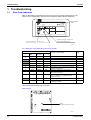
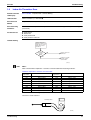
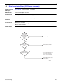
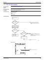
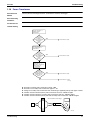
1.4
Troubleshooting
Indoor Air Thermistor Error
64
Inspection OFF Unit No. Blinking
Remote Controller
LCD Display
Error Code
LED Indication
Remote Controller 4 Main Unit 5
Error Detection
Method
Temperature detected by inside air temperature sensor is used to detect errors.
Error Generating
Conditions
When value detected by inside air temperature sensor is -40ºC or below (open circuit) or 70ºC or higher
(short-circuit).
Possible Causes
Faulty sensor
Broken wire
Faulty control PCB
Faulty contact in connector
Troubleshooting
Remove Indoor air
thermistor (R1T) from
X12A (3P) on control
PCB, and measure
resistance.
Is
thermistor
normal?
Note 1
NO
Replace indoor air
thermistor.
YES
If there is no faulty
contact, replace
control PCB.
(HF003)
Note:
Note 1:
Refer to the thermistor temperature - resistance conversion table when measuring resistance.
Thermistor temperature - resistance conversion table
Thermistor
temperature
Sensor resistance
Thermistor
temperature
Sensor resistance
-10ºC or less
108kΩ or more
22ºC
Approx. 23kΩ
-5ºC
Approx. 85kΩ
24ºC
Approx. 21kΩ
0ºC
Approx. 66kΩ
26ºC
Approx. 19kΩ
5ºC
Approx. 51kΩ
28ºC
Approx. 18kΩ
10ºC
Approx. 40kΩ
30ºC
Approx. 16kΩ
14ºC
Approx. 33kΩ
35ºC
Approx. 13kΩ
16ºC
Approx. 30kΩ
40ºC
Approx. 11kΩ
18ºC
Approx. 27kΩ
50ºC or more
7kΩ or less
20ºC
Approx. 25kΩ
If measured value deviates significantly from above values, thermistor is faulty.
Use tester to check resistance
Continuity check
(HL028)
Troubleshooting
39
Troubleshooting
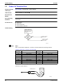
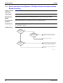
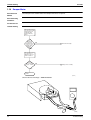
1.5
Si71-502
Outdoor Air Thermistor Error
65
Remote Controller
LCD Display
Error Code
LED Indication
Remote Controller 4 Main Unit 5
Error Detection
Method
Temperature detected by outside air temperature sensor is used to detect errors.
Error Generating
Conditions
When value detected by outside air temperature sensor is -40ºC or below (open circuit) or 70ºC or higher
(short-circuit).
Possible Causes
Inspection OFF Unit No. Blinking
Faulty sensor
Broken wire
Faulty control PCB
Faulty contact in connector
Troubleshooting
Remove outdoor air
thermistor (R2T) from
X13A (2P) on control
PCB, and measure
resistance.
Is
thermistor
normal?
Note 1
NO
Replace outdoor
air thermistor.
YES
If there is no faulty
contact, replace
control PCB.
(HF004)
Note:
Note 1:
Refer to the thermistor temperature - resistance conversion table when measuring resistance.
Thermistor temperature - resistance conversion table
Thermistor
temperature
Sensor resistance
Thermistor
temperature
Sensor resistance
-10ºC or less
108kΩ or more
22ºC
Approx. 23kΩ
-5ºC
Approx. 85kΩ
24ºC
Approx. 21kΩ
0ºC
Approx. 66kΩ
26ºC
Approx. 19kΩ
5ºC
Approx. 51kΩ
28ºC
Approx. 18kΩ
10ºC
Approx. 40kΩ
30ºC
Approx. 16kΩ
14ºC
Approx. 33kΩ
35ºC
Approx. 13kΩ
16ºC
Approx. 30kΩ
40ºC
Approx. 11kΩ
18ºC
Approx. 27kΩ
50ºC or more
7kΩ or less
20ºC
Approx. 25kΩ
If measured value deviates significantly from above values, thermistor is faulty.
Use tester to check resistance
Continuity check
(HL028)
40
Troubleshooting
Si71-502
1.6
Troubleshooting
Damper System Error (Alarm)
6A
Inspection OFF Unit No. Blinking
Remote Controller
LCD Display
Error Code
LED Indication
Remote Controller 4 Main Unit 5
Error Detection
Method
Measurement of damper motor limit ON/OFF time.
Error Generating
Conditions
When damper motor limit switch 1 (or 2) remains ON (or OFF) for more than a certain time duration
after ventilation mode is changed.
When damper motor limit switch 1 (or 2) repeats ON/OFF operations after damper motor 1 (or 2) stops.
Possible Causes
Faulty damper motor or limit switch
Broken wire in cable
Faulty contact in connector (including relay connector)
Faulty control PCB assembly
Troubleshooting
Is
relay
connector of
damper motor unit
connected?
NO
Connect relay connector.
YES
Check connectors
(X3A or X4A) (X5A or
X6A) on PCB assembly
of damper motor unit.
Are connectors
connected?
YES
Is
damper
motor unit
operating
normally?
Note 1
NO
NO
YES
Connect connectors.
Replace damper motor unit.
Replace control PCB assembly.
(HF005)
Note:
Note 1:
Place tester probes on connectors of limit switch. Move switch by hand and check continuity. If tester
indicates 0Ω when limit switch turns on, and infinity when it turns off, limit switch is normal.
Place tester probes on connectors of damper motor and check resistance. If tester indicates approx. 17
kΩ in 200-V model, damper motor is normal.
Check resistance and voltage
(HL029)
Troubleshooting
41
Troubleshooting
1.7
Si71-502
Damper System Error (Alarm)
6A
Remote Controller
LCD Display
Error Code
LED Indication
Remote Controller 5 Main Unit 5
Error Detection
Method
Measurement of damper motor limit switch ON/OFF time and temperatures detected by outdoor and indoor
air thermistor.
Error Generating
Conditions
When damper system error (alarm) and indoor (or outdoor) thermistor error are generated at the same
Inspection Blinking Unit No. Blinking
time.
When damper system error (alarm) occurs and values of indoor and outdoor air thermistor meet frost
conditions.
Possible Causes
Faulty damper motor or limit switch
Faulty indoor air thermistor
Faulty outdoor air thermistor
Frosting
Broken wire in cable
Faulty contact in connector (including relay connector)
Faulty control PCB assembly
Troubleshooting
Check error record on
malfunction history
display in service
mode.
Are
"6A" and "64"
or "65" recorded?
NO
Take corrective measures
specified for damper system
error (alarm).
(Remove the cause of problem,
and reset display.)
YES
Are
"64" and "65"
recorded?
NO
Take corrective measures
specified for damper system
error (alarm) and indoor and
outdoor air thermistor errors.
YES
Is "64" recorded?
NO
Take corrective measures
specified for damper system
error (alarm) and outdoor air
thermistor error.
YES
Take corrective measures
specified for damper system
error (alarm) and indoor and
outdoor air thermistor error.
(HF006)
42
Troubleshooting
Si71-502
1.8
Troubleshooting
Dedicated LCD Remote Controller
88” remains on remote controller display.
When “88” remains on remote controller display.
When “
Error Detection
Method
Error Generating
Conditions
Possible Causes
Master-slave setting of remote controller
Remote controller PCB assembly error
Main unit PCB assembly error
Troubleshooting
Check to see if masterslave remote controller is
used.
Is
master-slave
remote controller
used?
YES
Change master-slave selection
switch to set proper masterslave relation.
One should be set to Master,
and the other set to Slave.
NO
Check microcomputer
operation monitor on
main unit PCB.
YES
Is it flashing?
Replace remote controller.
NO
Replace main unit PCB.
(HF007)
Dedicated Remote Controller
Remote controller
PCB assembly
Master-slave
selection switch
(HL030)
Main Unit PCB
CN1
CN2
CN3
CN4
CN7
Exhaust
air fan
CN10 CN11 CN5 CN6 CN12
CN13
Supply
air fan
CN8
N
FuL 10A
L
KRP
50-2
CN9
LED A
(Microcomputor Operation Monitor)
P2
P1
F1
F2
J1
J2
JC
(HL031)
Troubleshooting
43
Troubleshooting
1.9
Si71-502
Data Transmission Error (Between LCD Remote Controller and Main Unit)
U5
Remote Controller
LCD Display
Error Code
LED Indication
Remote Controller 5 Main Unit 5
Error Detection
Method
Microcomputer checks if data is transmitted properly between main unit and remote controller.
Error Generating
Conditions
When data transmission is not performed correctly for a certain time period.
Possible Causes
Faulty connection of remote controller cable
Faulty remote controller cable
External factor (noise, etc.)
Inspection Blinking Unit No. Blinking
Troubleshooting
Check connection of
remote controller cable to
control PCB assembly on
terminal board.
Is
connection
cable between
main unit and remote
controller
properly
wired?
NO
Correct wiring.
YES
Is
remote
controller cable
normal?
Note 1
NO
Replace remote controller
cable.
YES
Possibility of external factor
(instead of equipment error).
(HF008)
Note:
Note 1:
1. Use tester to check continuity of remote controller cable.
Disconnect cable from main unit terminal board and remote controller terminal board. Measure
resistance between wires in cable. Resistance should be ∞ MΩ (infinity).
2. Use tester to check voltage at terminal board.
Check with power turned on.
With remote controller cable disconnected, voltage between P1 and P2 on terminal board should be
approx. 16 VDC. If measured value is not approx. 16 VDC, PCB assembly is faulty.
Connect remote controller cable and disconnect remote controller. Voltage at the end of remote
controller cable should be approx. 16 VDC. If measured value is not 16 VDC, remote controller cable is
faulty.
Connect remote controller cable and remote controller. Voltage between P1 and P2 on remote
controller terminal should be approx. 16 VDC. If measured valued is not 16 VDC, remote controller is
faulty.
P1 P2
JC J2 J1 F2 F1 P2 P1
Main unit PCB
LCD remote
controller
Remote
controller
for heat
reclaim
ventilation unit
(HL032)
44
Troubleshooting
Si71-502
Troubleshooting
1.10 Data Transmission Error (LCD Remote Controller)
U5
Remote Controller
LCD Display
Error Code
LED Indication
Remote Controller 5 Main Unit 5
Error Detection
Method
Microcomputer checks if data is transmitted properly between main unit and remote controller.
Error Generating
Conditions
When data transmission is not performed correctly for a certain time period.
Possible Causes
Erroneous connection
Faulty remote controller setting
Faulty remote controller
Inspection Blinking Unit No. OFF
Troubleshooting
Is
remote
controller
other than
dedicated LCD
remote controller
connected to
remote
controller
cable?
NO
Correct wiring.
YES
Is
master-slave
remote control
used?
NO
Replace remote controller.
YES
Is
master-slave
selection switch
properly set?
NO
Set one master-slave selection
switch to Master, and set the
other to Slave. Then turn off
power, and restart operation.
YES
Replace either master or slave
remote controller.
(HF009)
Troubleshooting
45
Troubleshooting
Si71-502
1.11 Data Transmission Error (Between LCD Master Remote Controller and Slave
Remote Controller)
U8
Remote Controller
LCD Display
Error Code
LED Indication
Remote Controller 1 Main Unit 5
Error Detection
Method
Microcomputer checks if data is transmitted properly between master-slave remote controller.
Error Generating
Conditions
When data transmission is not performed correctly for a certain time period.
Possible Causes
Faulty remote controller setting
Faulty remote controller
Inspection Blinking Unit No. OFF
Troubleshooting
Is
master-slave
remote control
used?
NO
Is
master-slave
NO
selection switch set
to Master?
YES
Set master-slave selection switch to
Master. Turn off power, then restart.
YES
Replace remote controller.
Is
master/slave
selection switch
properly
set?
NO
Set one master-slave selection switch to
Master, and set the other to Slave. Then
turn off power, and restart operation.
YES
Replace either master or slave remote
controller.
(HF010)
46
Troubleshooting
Si71-502
Troubleshooting
1.12 Field Setting Error
UA
Remote Controller
LCD Display
Error Code
LED Indication
Remote Controller 1 Main Unit 5
Inspection Blinking Unit No. OFF
Error Detection
Method
Error Generating
Conditions
Possible Causes
Faulty combination of remote controller
More than 16 units connected to remote controller cable.
Faulty remote controller
Troubleshooting
Is
combination
of remote
controller and heat
reclaim ventilation
unit (air
conditioner)
correct?
NO
Check the system, and correct
connections.
Refer "Combination-Right or Wrong"
YES
Are
17 or more
units connected
to remote
controller
cable?
NO
Change connections so that 16
or fewer units are connected to
remote controller cable.
YES
Replace remote controller.
(HF011)
<Combination-Right or Wrong>
Troubleshooting
Main body
Remote controller
Heat reclaim ventilation unit only
Heat reclaim ventilation unit
Right/Wrong
Right
Heat reclaim ventilation unit only
Air conditioner
Right
Heat reclaim ventilation unit + air-conditioner
Heat reclaim ventilation unit
Wrong
Heat reclaim ventilation unit + air-conditioner
Air-conditioner
Right
47
Troubleshooting
Si71-502
1.13 Overlapping Central Control Address
UC
Remote Controller
LCD Display
Error Code
LED Indication
Remote Controller 4 Main Unit 5
Error Detection
Method
Remote controller microcomputer checks for double-setting of addresses.
Error Generating
Conditions
When same address is set to two or more units.
Possible Causes
Overlapping of central control address
Faulty remote control
Inspection ON Unit No. ON
Troubleshooting
Change central
control address
settings using remote
controller.
Then, turn off power,
and restart.
Does
equipment reset
properly?
NO
Replace remote controller.
YES
End of correction procedure.
(HF012)
48
Troubleshooting
Si71-502
Troubleshooting
1.14 Main Unit PCB Assembly
Error Detection
Method
Check microcomputer operation monitor.
Error Generating
Conditions
When main unit PCB assembly does not operate.
When communication circuit errors.
Possible Causes
Fuse (excess current)
Power transformer
Noise
Main unit PCB
Troubleshooting
Turn off power, then
restart.
YES
Does equipment
reset properly.
Noise may be causing erroneous
operation. If power reset does not
solve the problem, replace main unit
PCB.
NO
With remote controller
disconnected, check
microcomputer operation
monitor.
NO
Is it flashing?
YES
Is monitor indicator
Off?
After checking
other possible
causes, replace
PCB assembly.
NO
YES
There may be a malfunction in main
unit PCB fuse, main unit PCB or power
transformer.
Check fuse and transformer. If they are
normal, replace PCB.
Monitor indicator remains
On.
Replace main unit PCB.
(HF013)
Main unit PCB
CN1
CN2
CN3
CN4
CN7
Exhaust
air fan
CN10 CN11 CN5 CN6 CN12
CN13
Supply
air fan
CN8
N
FuL 10A
L
KRP
50-2
CN9
LED A
(Microcomputor Operation Monitor)
P2
P1
F1
F2
J1
J2
JC
(HL031)
Troubleshooting
49
Troubleshooting
Si71-502
1.15 Dedicated LCD Remote Controller
When no indication is displayed on remote controller
Error Detection
Method
Check to see if remote controller displays indication.
Error Generating
Conditions
Possible Causes
Troubleshooting
Disconnect remote
controller cable from
both main unit
terminal board and
remote controller
terminal board.
Using tester, check
continuity between
two wires in cable.
Is
measured
value ∞ MΩ
(infinity)?
NO
There may be shorting in
remote controller cable.
Check 1
YES
With remote
controller cable
disconnected from
main unit PCB, check
voltage between P1
and P2 on main unit
terminal board.
Is
measured
value approx. 16
VDC?
NO
Main unit PCB may be
faulty.
Check 2
YES
Connect remote
controller cable to
main unit PCB, and
disconnect remote
controller. Check
voltage at the end of
cable on remote
control side.
Is
measured
value approx. 16
VDC?
YES
NO
There may be open circuit
in remote controller cable.
Check 3
Remote control PCB may
be faulty.
(HF014)
Check 1, 2, 3 : Refer to page 51
50
Troubleshooting
Si71-502
Troubleshooting
1.16 How to Check
Check 1
Dedicated LCD remote controller (Option)
JC
J2
J1
F2
F1
P2
P1
Main unit PCB
(HL034)
Check 2
Dedicated LCD remote controller (Option)
JC
J2
J1
F2
F1
P2
P1
Main unit PCB
(HL035)
Check 3
Dedicated LCD remote controller (Option)
P1 P2
JC
J2
J1
F2
F1
P2
P1
LCD remote controller
Main unit PCB
Remote controller for
heat reclaim ventilation
(HL036)
Troubleshooting
51
Troubleshooting
Si71-502
1.17 Thermistor
Error Detection
Method
Remove thermistor and check resistance with tester.
Error Generating
Conditions
Possible Causes
Faulty thermistor
Broken wire
Faulty control PCB
Faulty contact in connector
Troubleshooting
Remove thermistor
from main unit PCB
(X12A, X13A), and
check resistance
using tester.
Is
resistance
as shown below?
NO
If measured value deviates significantly
from values in the table, thermistor is
faulty.
YES
Thermistor is normal.
(HF015)
Note:
Refer to the thermistor temperature - resistance conversion table when measuring resistance.
Thermistor temperature - resistance conversion table
Thermistor
temperature
Sensor resistance
Thermistor
temperature
Sensor resistance
-10ºC or less
108kΩ or more
22ºC
Approx. 23kΩ
-5ºC
Approx. 85kΩ
24ºC
Approx. 21kΩ
0ºC
Approx. 66kΩ
26ºC
Approx. 19kΩ
5ºC
Approx. 51kΩ
28ºC
Approx. 18kΩ
10ºC
Approx. 40kΩ
30ºC
Approx. 16kΩ
14ºC
Approx. 33kΩ
35ºC
Approx. 13kΩ
16ºC
Approx. 30kΩ
40ºC
Approx. 11kΩ
18ºC
Approx. 27kΩ
50ºC or more
7kΩ or less
20ºC
Approx. 25kΩ
If measured value deviates significantly from above values, thermistor is faulty.
Use tester to check resistance
Continuity check
(HL028)
52
Troubleshooting
Si71-502
Troubleshooting
1.18 Power Transformer
Error Detection
Method
Check resistance and voltage with tester, and insulation resistance with megger.
Error Generating
Conditions
Possible Causes
Troubleshooting
Check resistance of
primary side of
transformer.
Does
measured
resistance
deviate significantly
from values
shown
below?
YES
Transformer is faulty.
NO
Check resistance of
secondary side of
transformer.
Does
measured
resistance
deviate significantly
from values
shown
below?
YES
Transformer is faulty.
NO
Apply rated voltage to
primary side of
transformer, and check
output voltage of
secondary side
of transformer.
Does
measured
voltage deviate
significantly from
values shown
below?
YES
Transformer is faulty.
NO
Transformer is normal
(HF016)
Resistance of primary side of transformer: approx. 140Ω
Resistance of secondary side of transformer: approx. 1.9Ω
Voltage at secondary side of transformer when rated voltage is applied to primary side: approx. 26 VAC
Insulation resistance between primary side of transformer and case: 100 MΩ or higher
Insulation resistance between secondary side of transformer and case: 100 MΩ or higher
Insulation resistance between primary side and secondary side of transformer: 100 MΩ or higher
Check resistance and voltage
(HL037)
Troubleshooting
53
Troubleshooting
Si71-502
1.19 Damper Motor
Error Detection
Method
Check damper motor and limit switch when damper motor does not operate.
Error Generating
Conditions
Possible Causes
Troubleshooting
Place tester probes
at connectors of limit
switch, and check
continuity while
moving switch by
hand.
Is
measured
value 0 Ω
when limit switch
turns on, and
infinity when
it turns
off?
NO
Limit switch is faulty.
YES
Place tester probes
on connectors of
damper motor and
check resistance.
Is
measured
value of EJ type
approx. 17 kΩ?
NO
Damper motor is faulty.
YES
Damper motor is
normal.
(HF017)
Check resistance and voltage — DAMPER MOTOR
(HL038)
54
Troubleshooting
Si71-502
Part 8
Supplementary
Explanation
1. Supplementary Explanation ..................................................................56
1.1 Field Setting, Service Mode Operation...................................................56
Supplementary Explanation
55
Supplementary Explanation
Si71-502
1. Supplementary Explanation
1.1
Field Setting, Service Mode Operation
1.1.1
Field Setting
Initial setting (mode
Nos. 17, 27, 18, 28)
Field setting mode
Unit No.
Setting position No.
Setting switch No.
Mode No.
4
3
6
1, 7
5
2
(HL039)
Step 1
56
With equipment in normal mode, press the
setting mode.
button for more than 4 seconds to enter field
Step 2
Mode No.: UP ↔
Mode No.: DOWN
Use [MODE] and [AIR VOLUME] to select desired mode No.
Step 3
To setting heat reclaim ventilation units by group, press
No.
Step 4
Press
button to select desired setting switch No.
Step 5
Press
button to select desired setting position No.
Step 6
Press
button to enter settings.
Step 7
Press
button to return to normal mode.
button and select desired unit
Supplementary Explanation
Si71-502
Supplementary Explanation
Centralized control
group No. setting
(Mode No. 00)
Setting of
Individual No.
(Mode No. 30)
Field setting mode
Group No.
3
Mode No.
4
1, 5
2
Step 1
Supplementary Explanation
With equipment in normal mode, press the
setting mode.
(HL040)
button for more than 4 seconds to enter field
Step 2
Mode No.: UP ↔
Mode No.: DOWN
Use [MODE] and [AIR VOLUME] to select mode No.00 (30).
Step 3
Press
or
Step 4
Press
button once to enter settings.
Step 5
Press
button to return to normal mode.
button to select Group No.
57
Supplementary Explanation
1.1.2
Si71-502
Service Mode Operation
Turn on the forced
fan (Mode No.43)
Mode No.
Unit No.
3
1, 4
(HL041)
2
Step 1
58
With equipment in field setting mode, press the
service mode.
button for more than 4 seconds to enter
Step 2
Mode No.: DOWN
Mode No.: UP ↔
Use [MODE] and [AIR VOLUME] to select mode No.43.
Step 3
Use
Step 4
Press
to select desired Unit No.
button to return to normal mode.
Supplementary Explanation
Si71-502
Supplementary Explanation
Unit No.
reallocation (Mode
No.45)
Field setting mode
Unit No. before reallocation
Unit No. after reallocation
4
Mode No.
3
5
1, 6
4
Step 1
Supplementary Explanation
(HL042)
2
With equipment in field setting mode, press the
service mode.
button for more than 4 seconds to enter
Step 2
Mode No.: UP ↔
Mode No.: DOWN
Use [MODE] and [AIR VOLUME] to select mode No.45.
Step 3
Use
Step 4
Press
or
Step 5
Press
button once to enter settings.
Step 6
Press
button to return to normal mode.
to select setting Unit No.
button to select Unit No. after reallocation.
59
Supplementary Explanation
1.1.3
Si71-502
Field Setting
The following
shows the
procedure for field
setting using
remote controller of
new heat reclaim
ventilation unit.
BRC301B61
(HL044)
List of field setting mode Nos.
Centralized control group No. setting
00
General setting
10-29
Centralized control group No. setting (group)
30
Error record display
40
Sensor data
41
Forced fan ON
43
Individual setting
44
Unit No. reallocation
45
Step 1
To field setting mode
Step 2
Mode No. selection 1
Step 3
Mode No. selection 2
Step 4
Switch No. selection
(
Step 5
Position selection
(
Step 6
Position enter
Enters currently selected position.
Step 7
To normal mode
Exits field setting mode and enters normal mode.
In group control, use
60
Press
for more than 4 sec.
[Mode (00-30)]
→ [Mode (40-49)]
(Press
for more than 4 sec.) (Press
sec. )
Mode No.: UP ↔
→
[Mode (50-59)]
for more than 4
Mode No.: DOWN
) Switch No. selection
) Position selection
to select unit No.
Supplementary Explanation
Si71-502
1.1.4
Supplementary Explanation
LCD and Operation Panel (Reference Information)
The following
shows the
operation panel and
LCD of remote
controller of new
heat reclaim
ventilation unit.
BRC301B61
(HL045)
LCD
LCD is equipped with a new function that graphically displays currently selected ventilation mode, as
shown below.
(Ventilation mode: Auto)
Total heat exchange ventilation
mode
(HL046)
Normal ventilation mode
(HL047)
Display OFF in automatic
ventilation mode
(HL048)
(Ventilation mode: Total heat
exchange)
(HL049)
(Ventilation mode: Normal)
Normal ventilation mode
(HL050)
Display can be turned off using field setting 19 (29) - 7.
Supplementary Explanation
61
Supplementary Explanation
1.1.5
Si71-502
Ventilation Volume (Fresh-up)
Ventilation volume
(Fresh-up) setting
changes as follows.
(With Freshup)
(Without Freshup)
Low
Low
High
High
Low
Freshup
Function modes change in sequence every time
button is pressed.
High
Freshup
(HL051)
Inspection
Inspection operation is shown below.
Unit
0
Error code
00
Cyclic
(Normal screen)
“Inspection”
“Inspection” indication flashes.
(HL052)
62
Supplementary Explanation
Si71-502
1.1.6
Supplementary Explanation
Field Setting
(Example of setting operation)
Centralized control
group No. setting
(mode No.: 00)
1.
2.
3.
4.
5.
Press
for more than 4 seconds.
Set mode No. to “00” using
or
.
Set centralized control group No. using
[
] or
Enter displayed group No. by pressing
.
Press
to return to normal operation mode.
Centralized control
group No. setting
(mode No.: 30)
For group control, the following step must be performed.
(*) Set unit No. using
.
[
].
Unit No.
(HL053)
Mode No.
Centralized
control group No.
Procedure for
entering individual
settings (mode No.:
44)
The setting is generally the same for all units in the same group control system. However, the setting of
selected units can be fixed by the following method.
< Example >
High
High
Low
Ventilation volume
at High
Ventilation volume fixed at Low
1.
2.
3.
4.
5.
6.
Press
for more than 4 seconds.
Set mode No. to “44” using
or
Set unit No. using
.
Set ventilation mode using
[
].
Set ventilation volume using
[
].
Enter settings by pressing
.
(HL054)
.
Ventilation mode
(heat reclaim ventilation unit)
Unit No.
A
Mode No.
Supplementary Explanation
Ventilation volume
(heat reclaim ventilation unit)
(HL055)
63
Supplementary Explanation
Si71-502
Individual Settings
Heat Reclaim Ventilation Unit
64
Ventilation Volume
Ventilation Mode
As indicated by LCD
As indicated by LCD
Supplementary Explanation
Si71-502
Part 9
Operation Manual
1.
2.
3.
4.
5.
6.
Operation Manual
Safety Cautions.....................................................................................68
What to do Before Operation ................................................................71
Operation Procedure.............................................................................78
Maintenance (for a Qualified Service Person Only) ..............................85
Troubleshooting ....................................................................................90
After-sales Service ................................................................................93
65
Si71-502
OPERATION MANUAL
Total Heat Exchanger
HRV (Heat Reclaim Ventilation)
MODELS
(Ceiling mounted duct type)
VAM 150GJVE
VAM 250GJVE
VAM 350GJVE
VAM 500GJVE
VAM 650GJVE
VAM 800GJVE
VAM 1000GJVE
VAM 1500GJVE
VAM 2000GJVE
3P034927-5J EM03A029 (0511)
66
FS
HT
Operation Manual
Si71-502
HRV
HRV; Heat Reclaim Ventilation
Before using the DAIKIN HRV, be sure to read this operation manual thoroughly. If you have any problems
or there is a malfunction, please refer to this operation manual.
Please keep this manual for your future reference whenever you do not understand how to use it when
something is wrong with the unit during the operation.
Operation Manual
67
Safety Cautions
Si71-502
1. Safety Cautions
Read the following cautions carefully and use your equipment properly.
This unit comes under the term “appliances not accessible to the genetic public.”
There are two kinds of safety cautions and tips listed here as follows:
Warning......Improper handling can lead to such serious consequences as death or severe injury.
Caution.......Improper handling can lead to injury or damage. It could also have serious
consequences under certain conditions.
Note
• These instructions will ensure proper use of the equipment.
Be sure to follow these important safety cautions.
Keep these warning sheets handy so that you can refer to them if needed.
Also, if this equipment is transferred to a new user, make sure to hand over this user’s manual to the new
user.
Warning
(During Opertaion)
• When the unit is in abnormal conditions (smell of something burning, etc.), cut off the power, and
contact your dealer.
Continued operation under such circumstances may result in a failure, electric shock, and fire.
• It is not good for your health to expose your body to the air flow for a long time.
• Do not operate the unit with a wet hand.
An electric shock may result.
• Open the windows and ventilate the room if flammable gas is leaked.
Insufficient ventilation when the unit is turned on or off may cause an explosion from sparks at the
electrical connection.
• Do not wash the HRV unit with water.
Electric shock or fire may result. (Not including air filters, etc.)
• Be sure to stop the unit and turn off the power when cleaning or inspecting it.
As the fan is rotating at high speed, it will cause injury.
• Never inspect or service the unit by yourself.
Ask a qualified service person to perform this work.
(The qualified service person)
Caution
(During Opertaion)
• Do not use the HRV unit for other purposes.
In order to avoid any quality deterioration, do not use the unit for cooling precision instruments, food,
plants, animals or works of art.
• Do not use burning appliances directly in the path of the air from the unit.
Incomplete combustion of the burning appliances may occur.
• Never expose little children, plants or animals directly to the air flow.
Adverse influence to little children, animals and plants may result.
• Neither place a flammable spray bottle near the HRV unit or indoor intake and outlet grills nor
perform spraying.
Doing so may result in a fire.
• Turn off the power when the unit is not to be used for long periods of time.
Otherwise, the unit may get hot or catch on fire due to dust accumulation.
• Do not block the intake or outlet grills.
If the fan does not blow air throughout the entire room it may cause machine trouble.
• Use gloves when cleaning.
Cleaning without gloves may cause injury.
• Do not operate the remote controller with wet hands.
This may cause electric shock.
• Never touch the internal parts of the controller.
Do not remove the front panel. Some parts inside are dangerous to touch, and a machine trouble may
happen. For checking and adjusting the internal parts, contact your dealer.
• Do not let any kind of sprays get on the remote controller (insecticides, cleaning materials, etc.)
This may cause breakage, deformation, or malfunction.
• Do not wipe the controller operation panel with benzine, thinner, chemical dustcloth, etc.
The panel may get discolored or the coating peeled off. If it is heavily dirty, soak a cloth in water-diluted
neutral detergent, squeeze it well and wipe the panel clean. And wipe it with another dry cloth.
• The appliance is not intended for use by young children or infirm persons without supervision.
68
Operation Manual
Si71-502
Safety Cautions
• Young children should be supervised to ensure that they do not play with the appliance.
• Consult with installation contractor for cleaning the inside of the air conditioner.
Wrong cleaning may make the plastics parts broken or cause failure of water leakage or electric shock.
• Do not place objects in direct proximity of the outdoor unit and do not let leaves and other debris
accumulate around the unit.
Leaves are a hotbed for small animals which can enter the unit. Once in the unit, such animals can cause
malfunctions, smoke or fire when making contact with electrical parts.
Warning
(For Installation)
• Do not attempt to install the unit yourself.
Ask your dealer for installation of the unit.
Incomplete installation performed by yourself may result in a water leakage, electric shock, and fire.
• Installation should be done following the installation manual.
Incorrect installation may cause leaking, electric shock, or fire. Injuries may result if the unit falls.
• Do not allow exhaust air to enter the outside air intake vent.
This may cause the interior of the room to become contaminated and harming the health.
• Locate the outside air intake vent so that it does not take in exhaust air which contains
combustion air, etc.
Incorrect installation may cause a loss of oxygen in the room, leading to serious accidents.
• All wiring must be performed by an authorized electrician.
To do wiring, ask your dealer. Never do it yourself.
• Make sure that a separate power supply circuit is provided for this unit and that all electrical work
is carried out by qualified personnel according to local lows and regulations.
Insufficient power circuit capacity or incorrect work may cause electric shock or fires.
• Install the unit on a foundation strong enough to withstand the weight of the unit.
A foundation of in sufficient strongth may result in the unit falling and causing injuries.
• Connect the remote controller to the correct model.
This may cause electric shock or fire.
• Do not connect additional electric wirings.
This may cause fire.
• Do not install the HRV unit at any place where flammable gas may leak out.
If the gas leaks out and stays around the unit, a fire may break out.
• Be sure to establish an earth.
Do not earth the unit to a utility pipe, arrester, or telephone earth.
Incomplete earth may cause electrical shock, or fire.
A high surge current from lightning or other sources may cause damage to the air conditioner.
• Be sure to install an earth leakage breaker.
Failure to install an earth leakage breaker may result in electric shocks, or fire.
Caution
(For Installation)
• Do not use the HRV unit or an air suction/discharge grille in the following places.
a. Place subjected to high temperature or direct flame.
Avoid a place where the temperature near the HRV unit and the air suction/discharge air grille
exceeds 40°C. If the unit is used at high temperature, deformed air filter and heat exchange element
or burned motor result.
b. Place such as kitchens or other places where oil fumes are present.
This may cause fire.
c. Place such as machinery plant and chemical plant where gas, which contains noxius gas or
corrosive components of materials such as acid, alkali, organic solvent and paint, is
generated.
Place where combustible gas leakage is likely.
This may cause gas poisoning or fires.
d. Place such as bathroom subjected to moisture.
Electric leak or electric shock and other failure can be caused.
e. Locations below freezing point.
f. Near machinery emitting electromagnetic waves.
Electromagnetic waves may disturb the operation of the control system and result in a malfunction of
the equipment.
g. Place subjected to much carbon black.
Carbon black attaches to air filter and heat exchange element, marking them unable to use.
• Is a snow protection measure taken?
For detail, consult your dealer.
Operation Manual
69
Safety Cautions
Si71-502
• Make sure the temperature and the humidity of the installation location is within the usage range,
not exceed the limit.
Do not install in cold storage or other locations with low temperatures or near heated pools. This may
cause fires or short circuits.
• Install the two outdoor ducts with down slope to prevent rainwater from entering the unit.
If this is not done completely, water may enter the building, damaging furniture, and cause electric shock
and fire.
• Insulate the two outdoor ducts to prevent dew condensation (and the indoor duct as well if
needed).
If this is not done completely, water may enter the building, damaging furniture, etc.
• Use electric insulation between the duct and the wall when using metal ducts to pass metal or
wire laths or metal plating into wooden buildings.
This may cause electric shock, short circuits, or fire.
• Arrange the drain hose to ensure smooth drainage.
Incomplete drainage may cause wetting of the building, furniture etc.
• Avoid placing the controller in a spot splashed with water.
Water coming inside the controller may cause an electric leak or may damage the internal electronic
parts.
• Never pull or twist the electric wire of a remote controller.
It may cause the unit to malfunction.
Warning
(For moving and
reinstalling/
repairing)
70
• Do not modify the unit.
This may cause electric shock or fire.
• Ask your dealer to move and reinstall the unit.
Incomplete installation may result in electric shock, and fire.
• Do not disassemble or repair the unit yourself.
This may cause electric shock or fire.
Contact your dealer to have such work done.
• When removing the unit, be sure not to tip it.
The water inside the unit may drip or leak out, and get on furniture, etc.
• Do not move or attempt to re-install the remote controller yourself.
Incorrect installation, may cause electric shock or fire. Contact your dealer to have such work done.
Operation Manual
Si71-502
What to do Before Operation
2. What to do Before Operation
This operation manual is for the following systems with standard control. Before initiating operation, contact
your Daikin dealer for the operation that corresponds to your system type and mark.
If your installation has a customized control system, ask your dealer for the operation that corresponds to
your system.
2.1
Names of Parts
MODELS
VAM150GJVE VAM250GJVE VAM350GJVE VAM500GJVE
VAM650GJVE VAM800GJVE VAM1000GJVE
fig 1 [1]
Operation Manual
71
What to do Before Operation
MODELS
Si71-502
VAM1500GJVE VAM2000GJVE
(3) Exhaust fan
(1) Hanger bracket
(7) Maintenance cover
(2)Duct connecting flange
(6) Control box
(10) Air supply fan
(5) Damper
(4) Air filter (Long life filter)
(8) Heat exchange elements
It exchanges the heat (temperature and humidity)
from indoors with the air taken in from outdoors,
changes the outside air to the same condition as
indoors and then brings it indoors.
(11) Remote controller
(Optional accessory)
Important
Sometimes when first using the unit, the
smell of the heat exchanging element may
be noticeable, but it is not harmful. The smell
will gradually go away as the unit is used.
(15) Maintenance
space for the air
filters, the heat
exchange elements
and control box
(14) OA
(Outdoor air)
[Fresh air
from outdoors]
(17) SA
(Supply air)
[Supply air
to room]
(13) EA
(Exhaust air)
[Exhaust air
to outdoors]
(16) RA
(Retun air)
[Return air
from room]
(12) Damper motor
fig 1 [2]
72
Operation Manual
Si71-502
2.2
What to do Before Operation
Remote Controller and Changeover Switch: Name and Function of Each
Switch and Display
25
NOT
AVAILABLE
NOT
AVAILABLE
27
Remote controller for VRV BRC1A61, 62
Remote controller for VRV BRC1C61
Remote controller for HRV BRC301B61
fig 3
• Only the items marked with an asterisk (* mark) are explanation relating to the functions and display of
the unit. Unmarked items are functions of the combined air conditioners. When using buttons for
functions which are not available (buttons which are not described in the text) will cause “NOT
AVAILABLE” to be displayed.
Contact your dealer for more detailed descriptions of those functions (buttons).
∗1 On/off button
Press the button and the system will start. Press the button again and the system will stop.
∗2 Operation lamp (red)
The lamp lights up during operation.
∗3 Display “
” (changeover under control)
May be displayed when combined with a VRV-system air conditioner.
While the indication is shown, the ON/OFF of HRVs cannot be operated by the HRV remote controller.
It is impossible to changeover heat/cool with the remote controller when this icon is displayed.
4 Display “
” (air flow flap)
This displays the direction and mode of the air flow flap of the combined air conditioner.
5 Display “
” (ventilation/air cleaning)
This display shows that the total heat exchange and the air cleaning unit are in operation. (These are
optional accessories.)
6 Display “
C ” (set temperature)
This displays the set temperature of the combined air conditioner.
It is not displayed when the unit is used as an independent system.
Operation Manual
73
What to do Before Operation
Si71-502
7 Display “
”“
”“
”“
”“
”
(operation mode)
This displays the operating status of the combined air conditioner.
• There is no “heating” for the VRVII system
(Cooling only type).
• “
” is only available for systems operating in cooling and heating at the same time.
∗8 Display “
” (programmed time)
This dispay shows the programmed time of the system start or stop.
9 Display “
TEST ” (inspection/test operation)
When the inspection/test operation button is pressed, the display shows the mode in which the system
actually is.
• Do not use under usual use
(service person/installer only).
10 Display “
” (under centralized control)
When this display shows, the system is under centralized control. (This is not a standard specification.)
During this indication appears on the display, the ON/OFF and timer operation may not be possible
with the HRV remote controllers.
∗11 Display “
” (fan speed)
This display shows the fan speed you have selected.
This is always displayed when you use the remote controller BRC301B61.
But, this is only displayed when the fan speed selection button is pressed. It normally displays the set
fan strength of the combined air conditioner. (only to use BRC1C61, BRC1A61, A62)
∗12 Display “
” (time to clean air filter)
Refer to “4-1 How to Clean the Air Filter”.
13 Display “
” (defrost/hot start)
It may be displayed when the combined air conditioner is in heating mode.
∗14 Timer mode start/stop button
Refer to the chapter “Operation procedure Programming start and stop of the system with timer.” (3-2)
∗15 Timer on/off button
Refer to the chapter “Operation procedure Programming start and stop of the system with timer.” (3-2)
∗16 Inspection/test operation button
Pressed during inspection or “test run.”
• Do not use under usual use.
(service person/installer only)
∗17 Programming time button
Use this button for programming start and/or stop time.
18 Temperature setting button
Use this button for setting the desired temperature of air conditioner combined with this unit.
∗19 Filter sign reset button
Refer to “4-1 How to Clean the Air Filter”.
20 Fan speed control button
Press this button to select the fan speed of air conditioner combined with this unit.
∗21 Operation mode selector button
Press this button to select the operation mode of air conditioner combined with this unit.
22 Air flow direction adjust button
Press this button to select the air flow direction of air conditioner combined with this unit.
23 Fan only/air conditioning selector switch
Set the switch to “
” for fan only operation or to “
” for heating or cooling operation.
24 Cool/heat changeover switch
Set the switch to “
” for cooling or to “
” for heating operation.
25 Remote controller thermo
This detects the temperature around the remote controller. This is not the same as the temperature of
return air from room (RA) by heat exchanger unit.
∗26 Display “
”“
”“
”
This displays the ventilation mode.
(BRC301B61, BRC1C61 and so on.)
(This is not displayed on the controller BRC1A61, 1A62)
74
Operation Manual
Si71-502
What to do Before Operation
∗27 Display “NOT AVAILABLE”
• “NOT AVAILABLE” may be displayed for a few seconds if the function for the button pressed is not
available for the unit or the air conditioner.
• “NOT AVAILABLE” is only displayed when none of the indoor units is equipped with the function in
question when running several units simultaneously. It is not displayed if the function is available on
even one of the units.
∗28 Ventilation fan mode selector button
(available only connecting the HRV unit)
This is pressed to switch the fan mode of the HRV unit.
∗29 Ventilation fan speed control button
(available only connecting the HRV unit)
This is pressed to control the fan speed of the HRV unit.
(Refer to item 11)
∗30 Display “
” (operation standby)
It indicates the pre-cooling/pre-heating operation. This unit is at stop and will start operation after the
pre-cooling/pre-heating operation is over.
Pre-cooling/pre-heating operation means the operation of HRVs is delayed during the startup
operation of linked air conditioners such a before the office hours.
During this period the cooling or heating load is reduced to bring the room temperature to the set
temperature in a short time.
31 Display “FRESH UP”
This displays the status of two fans. Refer to “Operation Procedure”
Note
Operation Manual
• In contradistinction to actual operating situations, the display on figure 3 shows all possible indications.
• If the filter sign lamp lights up, clean the air filter as explained in the chapter “MAINTENANCE”. After
cleaning and reinstalling the air filter: press the filter sign reset button on the remote controller. The filter
sign lamp on the display will go out.
75
What to do Before Operation
2.3
Si71-502
Explanation for Systems
This unit can be made a part of two different systems: as part of the combined operation system
used together with VRVII SYSTEM Air Conditioners or Sky-air series and as the independent
system using only the HRV. An operating remote controller is required when using the unit as an
independent system.
Ask your dealer what kind of system your system is set up for before operation.
For the operation of the remote controller for indoor unit and centralized controller, refer to the
instruction manual provided with each unit.
See the included operating manuals for details on how to operate each remote control.
OPERATION for EACH SYSTEM
Sample system
Independent system
• Independent system
HRV unit
Remote controller for
HRV unit (BRC301B61)
fig 2
[Operation]
The HRV unit can be started and stopped using the remote controller.
You can also select the ventilation amount and the ventilation mode.
Sample system
Combined operation system with VRV systems and Sky-air series
• Combined operation system with VRV systems and Sky-air series
Indoor unit
HRV unit
Remote controller
for indoor unit
fig 2
Indoor unit
HRV unit
Remote controller Remote controller
for indoor unit
for HRV unit (BRC301B61)
fig 2
[Operation]
The air conditioner remote controller starts and stops the air conditioner and the HRV unit.
You can also select the ventilation amount and the ventilation mode.
During intermediate periods when only the HRV unit is used without the air conditioner, select “ventilation”
with the operation selection button.
[Operation method]
The ON/OFF and timer operation can be performed using the HRV remote controllers.
(The indication of centralized control “
” appears on the display.)
Other operations can be performed using the HRV remote controllers.
76
Operation Manual
Si71-502
What to do Before Operation
Starting and stopping operations of the indoor unit and the HRV unit can be performed using the indoor
remote controllers.
(Refer to the section 3-2)
Centralized system
• Centralized system
HRV unit
Centralized
controller
Remote controller for
HRV unit (BRC301B61)
Remote controller
for indoor unit
fig 2
[Operation method]
When the HRV remote controllers is not connected, the Centralized controller controls the operation of the
HRV unit.
(Refer to the section 3-3)
When the HRV remote controllers is connected, operation can be started and stopped using the Cetralized
controller or the indoor and the HRV remote controllers.
During the indication of centralized control “
” appears on the display, the ON/OFF and timer
operation may not be possible with the HRV remote controllers.
Other operations can be performed using the HRV remote controllers. (Refer to the section 3-2, 3-3)
Operation Manual
77
Operation Procedure
Si71-502
3. Operation Procedure
3.1
Independent, Combined Operation
1·4
2
3
Remote controller for HRV BRC301B61
1·4
2
3
Remote controller for VRV BRC1C61
1·4
Remote controller for VRV BRC1A61, 62
fig 4
For non-independent systems, starting/stopping operation and timer operation may not be
possible.
Use the air conditioner remote control or the Centralized controller in such cases.
Press the on/off button. Operation lamp lights up and the system will start operation.
1
Press ventilation mode button if you wish to change the mode.
2
The display rotates through the following selections every time the button is pressed.
Automatic mode
3
Bypass mode
Press ventilation fan speed button if you wish to change the fan speed.
The display rotates through the following selections every time the button is pressed.
<In case of the remote controller “BRC301B61”>
Low
High
L
78
Heat exchange mode
H
Low
Fresh up L
FRESH UP
High
Fresh up
H
FRESH UP
Operation Manual
Si71-502
Operation Procedure
The display doesn’t disapper.
<In case of the remote controller “BRC1C61, BRC1A61, BRC1A62”>
High
Low
L
H
After the selection, the ventilation fan speed display dis-appears.
And the fan speed of the combined air conditioner regu-lary displays.
Stopping the system
Press start/stop one more time. The operation lamp will go off. The unit will stop.
• After stopping operation, the fan may continue operating for up to a minute.
• The fan may stop, but this is not a malfunction.
Note
• Do not change operations sunddenly.
It can result not only in malfunction but also failure of switches or relays in the remote controller.
• Never press the button of the remote controller with a hard, pointed object.
The remote controller may be damaged.
EXPLANATION OF FRESH UP
• If it is set to “Fresh up air supply” : The volume of outdoor air supplied into the room is larger than that of
room air exhausted outdoors. (This operation prevents the odor and moisture from kitchens and toilets
from flowing into the rooms.)
• If it is set to “Fresh up air exhaust” :The volume of room air exhausted outdoors is larger than that of
outdoor air supplied into the room. (This operation prevents the hospital odor and floating bacteria from
flowing out to the corridors.)
Note
• This does not be changed with the button of the remote controller BRC1C61. Ask your dealer for the set
up of FRESH UP.
EXPLANATION OF VENTILATION MODE
Automatic mode
:When combined with a VRVII-system air conditioner
The unit automatically switches between “
” and “
” based on information
from the VRVII system air conditioner (heating, cooling, fan, and set temperature)
and information from the HRV unit (indoor and outdoor temperatures).
The unit automatically switches between “
” and “
” when it is combined with
an air conditioner (Not producted by Daikin) and based on only the information from
the HRV unit (indoor and outdoor temperatures) when the HRV unit is operating
alone.
Total heat exchange mode
:Outdoor air passes through the heat exchange element and heat
exchanged air is sent into the room.
Bypass mode
:In this mode outdoor air does not through the heat exchange element, but rather sent
into the room as is.
ABOUT DIRECT DUCT CONNECTION SYSTEM
Installation Examples
Direct duct connection system
(HC0007)
Independent duct system
(HC0008)
Operation Manual
79
Operation Procedure
Si71-502
The HRV unit cannot be operated independently when the air conditioner is connected to the HRV
unit via a duct. When using the HRV unit, set the air conditioner to “fan” mode on weak fan
strength.
Operation mode display
“Ventilation” is displayed.
Operation mode
selector button
hr
hr
TEST
NOT
AVAILABLE
TEST
Remote controller
for indoor unit
• Each time you press the operation selection button, the operation mode display will change as shown in
the figure below.
Example 1:
In case of the remote controller “BRC1C61” and as equivalent.
Display changes as below.
When air conditioner and HRV
unit are not connected via duct
<Operation mode>
VRV:
Cooling mode
HRV:
Heat exchange mode
VRV:
Fan mode
HRV:
Heat exchange mode
VRV:
Stopping
HRV:
Heat exchange mode
When air conditioner and HRV
unit are connected via duct
<Operation mode>
VRV:
Cooling mode
HRV:
Heat exchange mode
VRV:
Fan mode
HRV:
Heat exchange mode
NOTE) Current Ventilation mode can be visible and selected on the remote controller.
80
Operation Manual
Si71-502
Operation Procedure
Example 2:
In case of the remote controller “BRC1A61,62”
Display changes as below.
When air conditioner and HRV
unit are not connected via duct
<Operation mode>
VRV:
Cooling mode
HRV:
Heat exchange mode
VRV:
Fan mode
HRV:
Heat exchange mode
VRV:
Stopping
HRV:
Heat exchange mode
When air conditioner and HRV
unit are connected via duct
<Operation mode>
VRV:
Cooling mode
HRV:
Heat exchange mode
VRV:
Fan mode
HRV:
Heat exchange mode
NOTE) Current Ventilation mode doesn’t be displayed.
• When the display shows “
” (time to clean air filter), ask a qualified service person to clean the filters
(Refer to the chapter “Maintenance”).
Operation Manual
81
Operation Procedure
3.2
Si71-502
Programming Start and Stop of the System with Timer
1
2
3
Remote controller for HRV BRC301B61
1
3
2
Remote controller for VRV BRC1C61
1
3
2
Remote controller for VRV BRC1A61,62
fig 5
• The timer is operated in the following two ways.
Programming the stop time
“”. The system stops operating after the set time has
elapsed.
Programming the start time “
”. The system starts operating after the set time has elapsed.
• The start and the stop time can be simultaneously programmed.
1
Press the timer mode start/stop button “
” several times and select the mode on the display.
• For setting the timer stop “
”
• For setting the timer start “
”
Each time the button is pushed, the indication changes as shown below.
“No indication”
“
82
”
“
”
Operation Manual
Si71-502
Operation Procedure
Press the programming time button and set the time for stopping or starting the system.
2
Each time this button is pressed, the time advances or goes backward by 1 hour.
• The timer can be programmed for a maximum of 72 hours.
• Each time when “
” is pushed, the time advances one hour.
Each time when “
” is pushed, the time goes back one hour.
Press the timer on/off button.
3
The timer setting procedure ends. The display “
” or “
” changes from flashing light
to constant light.
• After the timer is programmed, the display shows the remaining time.
For cancelling the timer operation, push the timer on/off button “
” once again.
The indication disappears.
Note
• When setting the timer off and on at the same time, repeat the above procedure (from “
once again.
DETAIL EXPLANATION
When you want to stop operation after a desired time,
Example:
Set the time to “8”.
↓
“
8hr
1
” to “
3
”)
” will display.
Stops operation 8 hours after the reservation is complete.
The program will be cleared after the operation stops.
• Set the stop time during operation.
When you want to start operation after a desired time has elapsed
Example:
Set the time to “8”.
↓
“
8hr
” will display.
Starts operation 8 hours after the reservation is complete.
The reservation is cancelled after operation starts.
• Set the start time while the unit is stopped.
• The remaining time will count at the same time after reservation is complete.
See the example below if you want to reserve “off after time” and “on after time” at the same time.
For example: (Refer to figure below)
When the timer is programmed to stop the system after 3 hours and start the system after 4 hours, the
system will stop after 3 hours and start 1 hour later.
Example:
hr
hr
• Setting “off after 3 hours” and “on after 4 hours” will
↓
• Operation will stop after 3 hours.
Operation will then start in 1 hour from the time it stopped.
Operation Manual
83
Operation Procedure
3.3
Si71-502
Nighttime Free Cooling Operation
〈AUTOMATIC HEAT PORGE FUNCTION AT NIGHT〉
The nighttime free cooling is an energy-conserving function which works at night when the air conditioners
is off, reducing the cooling load in the morning when the air conditioner is turned on by ventilating rooms
which contain office equipment which raises the room temperature.
• Nighttime free cooling only works during cooling and when connected to Building Multi or VRV systems.
• Nighttime free cooling is set to “off” in the factory settings; so request your dealer to turn it on if you
intend to use it.
40
(a)
30
20
(c)
(b)
(e)
OFF
(d)
Operating state Temperature (˚C)
Operation image
ON
OFF
Nighttime free cooling operation
OFF
22:00
24:00
(time)
Following morning
(a) Outside temperature
(b) Indoor temperature
(c) Set temperature
(d) Operating state of Air conditioner
(e) Operating state of Total heat exchanger
EXPLANATION OF NIGHTTIME FREE COOLING OPERATION IMAGE
The unit compares the indoor and outdoor temperatures after the air conditioning operation stops for the
night. If the following conditions are satisfied, the operation starts, and when the indoor temperature
reaches the air conditioning setting, the operation stops.
<Conditions>
(1) the indoor temperature is higher than the air conditioning setting and
(2) the outdoor temperature is lower than the indoor temperature,
If the above conditions are not satisfied, reevaluation is made every 60 minutes.
Note
84
• The night purge operation works when the HRV unit is off. Therefore, it is not possible to stop the night
purge operation, though the forced off is input from the optional controllers for centralized control.
Operation Manual
Si71-502
Maintenance (for a Qualified Service Person Only)
4. Maintenance (for a Qualified Service Person Only)
ONLY A QUALIFIED SERVICE PERSON IS ALLOWED TO PERFORM MAINTENANCE
4.1
Warning
• BEFORE OBTAINING ACCESS TO TERMINAL DEVICES, ALL POWER SUPPLY CIRCUITS MUST
BE INTERRUPTED.
• To clean the HRV, or maintenance be sure to stop operation, and turn the power switch off. It may cause
electrical shock and it is very dangerous to touch the rotating part.
• Do not wash the HRV with water.
Doing so may result in an electric shock.
Caution
• Use gloves when cleaning.
Cleaning without gloves may cause injury.
• Watch your step.
Use caution, as this requires working in high places.
• Do not use benzene or thinner to clean the outside surfaces of the air conditioner.
This may cause cracks, discoloration, or machine trouble.
How to Clean the Air Filter
Clean the air filter when the display shows “
”
(TIME TO CLEAN AIR FILTER).
It will display that it will operate for a set amount of time.
CLEANING FREQUENCY
AT LEAST ONCE EVERY YEARS
(FOR GENERAL OFFICE USE)
(CLEAN THE MORE FREQUENTLY IF NECESSARY.)
• Increase the frequency of cleaning if the unit is installed in a room where the air is etermely
contaminated.
• If the dirt becomes impossible to clean, change the air filter (Air filter for exchange is optional).
1. Detach the maintenance cover.
Go into ceiling through the inspection hatch, remove binding metal of maintenance cover and take it
off.
MODELS VAM150GJVE-1000GJVE
MODELS VAM1500GJVE
VAM2000GJVE
fig 6
Operation Manual
85
Maintenance (for a Qualified Service Person Only)
Si71-502
2. Detach the air filter.
Take out from the heat exchange elements.
MODELS VAM150GJVE-1000GJVE
MODELS VAM1500GJVE
VAM2000GJVE
fig 7
3. Clean the air filter.
Use vacuum cleaner A) or wash the air filter with water B).
A) Using a vacuum cleaner
B) Washing with water
When the air filter is very dirty, use soft brush and neutral detergent.
After cleaning, remove water and dry in the shade.
Note
86
• Do not wash the air filter with hot water of more than 50°C, as doing so may result in discoloration and/or
deformation.
• Do not expose the air filter to fire, as doing so may result in burning.
• Do not use gasoline, thinner, or other organic solvents.
This may cause discoloration or deformation.
Operation Manual
Si71-502
Maintenance (for a Qualified Service Person Only)
4. Fix the air filter.
If the air filter is washed, remove water completely and allow to dry for 20 to 30 minutes in the shade.
When dried completely, install the air filter back in place.
Note
• Be sure to install the air filter after servicing.
(Missing air filter causes clogged heat exchange element.)
The air filter is an optional item and the replacement is available.
5. Install the maintenance cover.
Refer to the section (4-1, 1).
For remote controllers which display the filter sign, turn on the power after maintenance, and press
the filter sign reset button.
∗Consult your dealer if you want to change the time setting for when the filter sign goes on.
Note
4.2
• Do not remove the air filter except when cleaning.
Breakdown may occur.
Optimum Operation
Observe the following precautions to ensure the system operates.
• When the display shows “
”, ask a qualified service person to clean the filters (Refer to
Maintenance).
• Do not operate the HRV unit in Bypass mode when the room air is under heating in winter or
when the outside temperature is 30°C or higher.
This may cause condensation to form on the main unit or on discharge grill, or around air supply opening.
• Keep the indoor unit and the remote controller at least 1 m away from televisions, radios, stereos,
and other similar equipments.
This may cause distorted picture or noise.
• Turn off the main power supply switch when it is not used for long periods of time. When the
main power switch is turned on, some watts of electricity is being used even if the system is not
operating.
• Do not install the remote controller where the indoor temperature and humidity, respectively, are
out of the range of 0-35°C and RH 40-80%.
This may cause malfunction.
• Do not install the remote controller where direct sunlight may fall on it.
This may cause discoloration or deformation.
Note
Operation Manual
• When the fan motor fails, the remote controller does not display any error code.
Usage under that status will lead to insufficient ventilation.
The air supply and exhaust fans should be checked once every one or two months.
You can make a simple check such as below way.
To check the wind flow, hold a bar of which the end has a string or other similar lightweight item over the
supply grille and exhaust grille.
87
Maintenance (for a Qualified Service Person Only)
4.3
Si71-502
How to Clean the Heat Exchange Element
CLEANING FREQUENCY
AT LEAST ONCE EVERY TWO YEARS
(FOR GENERAL OFFICE USE)
(CLEAN THE ELEMENT MORE FREQUENTLY IF NECESSARY.)
Warning
• Please exchange the heat exchange element if you find that the knob of the heat exchange
element is damaged or is deteriorated when cleaning it.
There is falling danger.
1. Detach the maintenance cover.
Refer to the section (4-1, 1).
2. Detach the air filter.
Refer to the section (4-1, 2).
3. Take out the heat exchange elements.
Pull out the air filter and then pull out the two heat exchanger elements.
MODELS VAM150GJVE-1000GJVE
MODELS VAM1500GJVE
VAM2000GJVE
fig 7
4. Use a vacuum cleaner to remove dust and foreign objects on the surface of the heat exchange
element.
• Use the vacuum cleaner equipped with a brush on the tip of the suction nozzle.
• Lightly contact the brush on the surface of the heat exchange element when cleaning.
(Do not crush the heat exchange element while cleaning.)
88
Operation Manual
Si71-502
Maintenance (for a Qualified Service Person Only)
Caution
(During Opertaion)
• Do not clean touching strongly with a vacuum cleaner. This may crush the mesh of the heat exchange
elements.
• Never wash the heat exchange element with water.
• Have your dealer professionally clean the filter if it is very dirty.
5. Put the heat exchange element on the rail and insert it securely in place.
6. Install the air filter securely in place.
(Refer to the section (4-1, 4))
7. Install the maintenance cover securely in place.
(Refer to the section (4-1, 5))
Caution
• Always use the air filter.
If the air filter is not used, heat exchange elements will be clogged, possibly causing poor performance
and subsequent failure.
4.4
Inspection of the Fan Moter
Note
Operation Manual
• When the fan motor fails, the remote controller does not display any error code.
Usage under that status will lead to insufficient ventilation.
The air supply and exhaust fans should be checked once every one or two months.
You can make a simple check such as below way.
To check the wind flow, hold a bar of which the end has a string or other similar lightweight item over the
supply grille and exhaust grille.
89
Troubleshooting
Si71-502
5. Troubleshooting
5.1
The Following Situations are not Malfunctions
• Operation does not start.
<Symptom>
The icon “
” (under centralized control) is displayed on the remote controller and pressing
the on/off button causes the display to blink for a few seconds.
<Cause>
This indicates that the central device is controlling the unit.
The blinking display indicates that the remote controller cannot be used.
<Symptom>
The fans rotates after 1 minutes when pressing on on/off button.
<Cause>
This indicates that the operation is in preparation.
Wait for about 1 minute.
• Operation stops sometimes.
<Symptom>
“U5” is displayed on the remote controller and the operation stops but then restarts after a few minutes.
<Cause>
This indicates that the remote controller is intercepting noise from electrical appliances other than the
HRV unit, and this prevents communication between the units, causing them to stop.
Operation automatically restarts when the noise goes away.
• “
” is displayed on the remote controller.
<Symptom>
It displays immediately after the power is turned on, and disappears after several seconds.
<Cause>
This indicates that the unit is checking whether or not the remote controller is normal.
It is only displayed temporarily.
5.2
If One of the Following Malfunctions Occurs, Take the Measures Shown Below
and Contact Your Daikin Dealer
The system must be repaired by a qualified service person.
DO NOT CHECK AND REPAIR OPENING INSIDE THE UNIT BY YOURSELF.
Warning
90
When the HRV is in abnormal conditions (smell of something burning, etc), cut off the power, and
contact your dealer.
Continued operation under such circumstances may result in a failure, electric shock, and fire.
• The unit does not operate at all.
a.Check if there is a power failure.
Measure:After power has been restored, start operation again.
b.Check if the fuse has blown.
Measure:Turn the power off.
ON
c.Check if breaker has worked.
Switch
Measure:Turn the power on with the breaker switch in the off position.
Trip position
Do not turn the power on with the breaker switch in the trip position.
Breaker
(Contact your dealer.)
OFF
• If a safety device such as a fuse, a breaker, or an earth leakage
breaker frequency actuates, or ON/OFF switch does not properly work.
Measure: Do not turn the power on.
• The remote control buttons do not work well.
Measure: Turn off the main power switch.
Operation Manual
Si71-502
Troubleshooting
• If the display “
T” (INSPECTION), “UNIT No.” and the OPERATION lamp flash and the
“MALFUNCTION CODE” appears.
OPERATION lamp
UNIT No.
INSPECTION
display
INDOOR UNIT No. in which
a malfunction occurs
MALFUNCTION CODE
Measure: Notify and inform the model name and what the malfunction code indicates to your Daikin
dealer.
• There are other malfunctions.
Measure: Stop the unit.
List of malfunction codes of Remote controller of the HRV-system
Operation
lamp
Inspection
indicator
Unit No.
Malfunction
code
On
Off
Blinking
64
On
Off
Blinking
65
Outdoor air thermistor malfunction
On
Off
Blinking
6A
Dumper-related malfunction
Blinking
Blinking
Blinking
6A
Dumper-related malfunction + thermistor
malfunction
Blinking
Blinking
Blinking
U5
Transmission error between the unit and remote
controller
Off
Blinking
Off
U5
Setting error of remote controller
Description
Indoor air thermistor malfunction
Off
Blinking
Off
U8
Transmission error between main remote
controller and sub remote controller
Off
Blinking
Blinking
UA
Incorrect combination with indoor unit and remote
controller.
On
Blinking
On
UC
Central control address over lapping
Blinking
Blinking
Blinking
UE
Transmission error between the unit and
centralized controller
In case of the malfunction with the code in white letters on the black background in the unit still
operates.
However, be sure to have it inspected and repaired and as soon as possible.
If other than the above error codes are displayed, there is a possibility that the problem in question
has occurred with a combined air conditioner or outdoor unit. See the operation manuals included
with the air conditioners or outdoor units for details.
5.3
If the System does not Properly Operate Except for the above Mentioned
Case, and None of the above Mentioned Malfunctions is Evident, Investigate
the System According to the Following Procedures.
1. The unit does not operate at all.
• Check if there is a power failure.
After power has been restored, start operation again.
• Check if the fuse has blown or breaker has worked.
Change the fuse or set the breaker.
2. Amount of discharged air is small and the discharging sound is high.
• Check if the air filter and heat exchange element are clogged.
Clean tha air filter and heat exchange element.
3. Amount of discharged air is large and so is the sound.
• Check if the air filter and heat exchange element are not installed.
Install the air filter and heat exchange element.
Operation Manual
91
Troubleshooting
5.4
Si71-502
The Following Malfunctions must be Cheched by a Qualified Service Person
1. Do not operate
• Are there any problems with the power or wiring?
Inspect the power and wiring.
• Are there any problems with the fan unit?
Inspect the fan motor and fan.
5.5
If the System does not Properly Operate Except for the above Mentioned
Case, and None of the above Mentioned Malfunctions is Evident, Contact Your
Dealer, and Request for Investigation the System According to the Following
Procedures by a Qualified Service Person
The following malfunctions must be cheched by a qualified service person. Do not check by
yourself.
• The unit does not operate at all.
a.Check if there is a power failure.
After power has been restored, start operation again.
b.Check if the fuse has blown.
Change the fuse.
c.Check if breaker has worked.
Contact your dealer.
d.Are there any problems with the power or wiring?
Inspect the power and wiring.
e.Are there any problems with the fan unit?
Inspect the fan motor and fan.
• Amount of discharged air is small and the discharging sound is high.
a.Check if the air filter and heat exchange element are clogged. (Check both SA and RA air filter. Check
both sides of elements.)
Clean the air filter and heat exchange element.
• Amount of discharged air is large and so is the sound.
a.Check if the air filter and heat exchange element are not installed.
Install the air filter and heat exchange element.
92
Operation Manual
Si71-502
After-sales Service
6. After-sales Service
After-sales service:
Warning
Operation Manual
• Do not modify the unit.
This may cause electric shock or fire.
• Do not disassemble or repair the unit.
This may cause electric shock or fire.
Contact your dealer.
• Do not remove or reinstall the unit by yourself.
Incomplete installation may cause a water leakage electric shock and fire.
Contact your dealer.
When asking your dealer to repair, inform related staff of the details as follows:
• Shipping date and installation date:
• Malfunction:
Inform the staff of the defective details.
(Malfunction code being displayed on the remote controller.)
• Name, address, telephone number
Repair where the warranty term is expired
Contact your dealer. If necessary to repair, pay service is available.
Minimum storage period of important parts
Even after a certain type of the HRV unit is discontinued, we have the related important parts in stock for
6 years at least.
The important parts indicate parts essential to operate the HRV unit.
Recommendations for maintenance and inspection
Since dust collects after using the unit for several years, the performance will be deteriorated to some
extent.
Taking apart and cleaning inside require technical expertise, so we recommend entering a maintenance
and inspection contract (at a cost) separate from normal maintenance.
Recommended inspection and maintenance cycles [Note: The maintenance cycle is not the same
as the warranty period.]
Table 1 assumes the following usage conditions.
• Normal use without frequent starting and stopping of the machine.
(Although it varies with the model, we recommend not starting and stopping the machine more than 6
times/hour for normal use.)
• Operation of the product is assumed to be 10 hours/day, 2500 hours/year.
93
After-sales Service
94
Si71-502
Operation Manual
Si71-502
Part 10
Appendix
1. Appendix ...............................................................................................96
1.1 Wiring Diagram.......................................................................................96
Appendix
95
Appendix
Si71-502
1. Appendix
1.1
Wiring Diagram
VAM150GJVE / VAM250GJVE / VAM350GJVE / VAM500GJVE / VAM650GJVE / VAM800GJVE / VAM1000GJVE
96
Appendix
Si71-502
Appendix
VAM1500GJVE / VAM2000GJVE
Appendix
97
Appendix
Si71-502
98
Appendix
Si71-502
Index
A
Abnormality control function ...................................22
Air conditioner link function ....................................22
Air Conditioner Link Operation ...............................25
Air conditioner link operation ..................................33
Air Filter (Long Life Filter) .....................................2, 3
Air Supply Fan ......................................................2, 3
Airflow rate setting switch interface ........................33
Automatic ventilation operation function ................22
C
Central data transmission interface ........................33
Centralized control function ....................................22
Centralized control group No. setting .....................60
Centralized control group No. setting (group) ........60
Centralized control group No. setting
(mode No.00) ..................................................63
(mode No.30) ..................................................63
Centralized control group No. setting (Mode No. 00)
Setting of Individual No. (Mode No. 30) ..........57
Centralized System ................................................10
Check microcomputer operation monitor. ..............49
Circuit Functions ....................................................33
Circuit Operations ..................................................32
CLEANING FREQUENCY .....................................16
Cold Area Mode .....................................................25
Combined Operation System with VRV Systems
and Skyair Series ............................................10
Control Box ..........................................................2, 3
Control microcomputer ...........................................33
D
Damper ................................................................2, 3
Damper limit switch interface .................................33
Damper Motor ........................................................54
Damper Plate .......................................................2, 3
Damper System Error (Alarm) ..........................41, 42
Data Transmission Error (Between LCD Master
Remote Controller
and Slave Remote Controller) .........................46
Data Transmission Error (Between LCD Remote
Controller and Main Unit) ................................44
Data Transmission Error
(LCD Remote Controller) ................................45
Dedicated LCD Remote Controller ...................43, 50
Dedicated Remote Controller .................................43
Direct duct connection with air conditioner .............23
Display OFF in automatic ventilation mode ............61
Duct Connection Flange .......................................2, 3
E
EEPROM ................................................................33
Error Code 60 ...................................................37, 38
Error Code 64 .........................................................39
Error Code 65 .........................................................40
Index
Error Code 6A ................................................. 41, 42
Error Code Indication ............................................ 36
Error Code U5 ................................................. 44, 45
Error Code U8 ....................................................... 46
Error Code UA ....................................................... 47
Error Code UC ...................................................... 48
Error record display ............................................... 60
Exhaust Air .......................................................... 2, 3
Exhaust Fan ........................................................ 2, 3
Explanation for Systems ....................................... 10
External Damper Operation
Essential Setting Changes .............................. 28
Essential Wiring .............................................. 28
Explanation of Functions ................................ 28
External input interface ......................................... 33
External link operation function ............................. 22
F
Fan motor, damper motor relay ............................. 33
Field Setting .......................................................... 60
Field Setting Error ................................................. 47
Field setting function ............................................. 22
Field Setting, Service Mode .................................. 26
Field Setting, Service Mode Operation ................. 56
Filter sign function ................................................. 22
Forced fan ON ....................................................... 60
FRESH UP ............................................................ 11
Fresh-up function .................................................. 22
Function of main connection terminal ................... 30
G
General Constructions ............................................ 2
General setting ...................................................... 60
Group function ....................................................... 22
H
Heat Exchange Element (X2) ................................ 17
Heat Exchange Element (X4) ................................ 17
Heat Exchange Elements .................................... 2, 3
How to Check ........................................................ 51
HOW TO OPERATE WITH TIMER ....................... 12
Humidifier operation control function ..................... 22
I
Independent operation of the HRV unit
using the Centralized controller
(DCS302C(A)61) ............................................ 14
Independent System ............................................. 10
Individual setting ................................................... 60
Individual Settings ................................................. 64
Indoor Air Thermistor Error .................................... 39
Initial setting (mode Nos. 17, 27, 18, 28) .............. 56
Inspection operation .............................................. 62
i
Si71-502
K
KRP50-2 .................................................................22
KRP50-2 interface ..................................................33
L
Remote Controller for VRV BRC1C51·61 ............. 13
Remote controller function .................................... 22
Remove thermistor and check resistance
with tester ....................................................... 52
Return Air ............................................................ 2, 3
Layout of switches on Printed Circuit Board ..........29
LCD and Operation Panel ......................................61
List of Control Functions ........................................22
List of field setting mode Nos. ................................60
List of malfunction codes displayed
by LCD remote controller ................................36
S
M
Thermistor ............................................................. 52
Thermistor interface .............................................. 33
Thermistor temperature - resistance
conversion table ................................. 39, 40, 52
Timer function ....................................................... 22
To clean the air filter .............................................. 17
to dry Air filter ........................................................ 17
Total heat exchange ventilation mode .................. 61
Troubleshooting function ....................................... 22
Turn on the forced fan (Mode No.43) .................... 58
Main Unit PCB ........................................................43
Main Unit PCB Assembly .......................................49
Maintenance Cover ........................................2, 3, 16
Maintenance for the Air Filter .................................16
Maintenance for the Heat Exchange Element ........19
Maintenance Space for The Air Filters,
Heat Exchange Elements
and Control Box ............................................2, 3
Microcomputer oscillation circuit ............................33
Microcomputer reset circuit ....................................33
N
Name Plate ..........................................................2, 3
Normal operation ....................................................23
Normal ventilation mode ........................................61
O
Operating the HRV Unit Using the Remote
Controller of the VRV-System
Air Conditioner ................................................13
Operation chart ......................................................23
Operation for INDIVIDUAL SYSTEM .....................11
Operation HRV Units with the Remote
Control exclusively for Air Conditioning
Operation. (BRC301B61) ................................11
Outdoor Air ...........................................................2, 3
Outdoor Air Thermistor Error ..................................40
Overall Alarm .........................................................37
Overall Malfunction ................................................38
Overlapping Central Control Address ....................48
Sensor data ........................................................... 60
Service Mode Operation ....................................... 58
Supply Air ............................................................ 2, 3
T
U
Unit No. reallocation .............................................. 60
Unit No. reallocation (Mode No.45) ....................... 59
V
Ventilation capacity changeover function .............. 22
Ventilation mode
Total heat exchange ....................................... 61
Ventilation mode changeover function .................. 22
Ventilation Operation Control ................................ 23
Ventilation operation control function .................... 22
Ventilation volume (Fresh-up) setting changes ..... 62
W
When no indication is displayed
on remote controller ....................................... 50
P
Power ON operation function .................................22
Power supply circuit ...............................................33
Power Transformer ................................................53
Power transformer ..................................................33
Pre-cool/pre-heat function ......................................22
Pre-cool/pre-heat operations ..................................24
Printed Circuit Board ..............................................29
Procedure for entering individual settings
(mode No.44) ..................................................63
Product Specification ...............................................6
R
Relay drive circuit ...................................................33
Remote control data transmission interface ...........33
Remote Controller ................................................2, 3
Remote Controller for HRV BRC301B61 ...............11
ii
Index
Si71-502
Drawings & Flow Charts
A
VAM250GJVE
VAM350GJVE
VAM500GJVE
VAM650GJVE
VAM800GJVE
Air Conditioner Link Operation
1 group link control ..........................................25
Link control of 2 or more groups ......................26
Air flow rate can be changed over .........................11
C
Centralized control group No. setting .............. 57, 63
Check 1 ..................................................................51
Check 2 ..................................................................51
Check 3 ..................................................................51
Check damper motor .............................................54
Check microcomputer operation monitor ...............49
Check resistance and voltage ................................41
Check resistance and voltage DAMPER MOTOR ..........................................54
Check resistance and voltage with tester ...............53
Circuit Configuration ..............................................32
Cold Area Mode .....................................................25
Connect remote controller cable and
remote controller .............................................44
D
H
HOW TO OPERATE WITH TIMER ....................... 12
I
Initial setting (mode Nos. 17, 27, 18, 28) .............. 56
Inspection operation .............................................. 62
L
LCD and Operation Panel ..................................... 61
M
Main Unit PCB ....................................................... 43
Main unit PCB ....................................................... 49
Maintenance Cover
VAM150~1000GJVE ...................................... 16
VAM1500~2000GJVE .................................... 16
Maintenance for the Heat Exchange Element ....... 19
Dedicated Remote Controller .................................43
Display OFF in automatic ventilation mode ............61
dry Air filter .............................................................17
N
E
O
Error Code 60 ................................................. 37, 38
Error Code 64 ........................................................39
Error Code 65 ........................................................40
Error Code 6A ................................................. 41, 42
Error Code Indication .............................................36
Error Code U5 ................................................. 44, 45
Error Code U8 ........................................................46
Error Code UA .......................................................47
Error Code UC .......................................................48
Explanation of Individual Functions
Direct duct connection with air conditioner ......23
Normal operation .............................................23
External Damper Operation
Essential Setting Changes ..............................28
Essential Wiring ...............................................28
Explanation of Functions .................................28
F
Field Setting ...........................................................60
Function of main connection terminal ....................30
G
General Constructions
VAM1000GJVE .................................................2
VAM1500GJVE .................................................3
VAM150GJVE ...................................................2
VAM2000GJVE .................................................3
Drawings & Flow Charts
................................................... 2
................................................... 2
................................................... 2
................................................... 2
................................................... 2
Normal ventilation mode ....................................... 61
Operation for Each System ................................... 10
P
Power Transformer ............................................... 53
Pre-cool/pre-heat operations ................................. 24
Printed Circuit Board ............................................. 29
Procedure for entering individual settings
(mode No. 44) ................................................ 63
R
Remote Controller for HRV BRC301B61 .............. 11
Remote Controller for VRV BRC1C51·61 ............. 13
Remove thermistor and check resistance
with tester ....................................................... 52
T
Take out the heat exchange elements
VAM150~1000GJVE ...................................... 17
VAM1500~2000GJVE .................................... 17
To clean the air filter .............................................. 17
Total heat exchange ventilation mode .................. 61
Turn on the forced fan (Mode No.43) .................... 58
U
Unit No. reallocation (Mode No.45) ....................... 59
Use tester to check resistance ........................ 39, 40
iii
Si71-502
V
Ventilation mode
Total heat exchange ........................................61
Ventilation mode changeover ................................12
Ventilation volume (Fresh-up) setting changes ......62
W
When “88” remains on remote controller display ...43
When no indication is displayed on
remote controller .............................................50
Wiring Diagram
VAM1500GJVE / VAM2000GJVE ...................97
VAM150GJVE / VAM250GJVE /
VAM350GJVE / VAM500GJVE /
VAM650GJVE / VAM800GJVE /
VAM1000GJVE ..................................96
iv
Drawings & Flow Charts
Ask a qualified installer or contractor to install this product. Do not try to install the product yourself.
Improper installation can result in water or refrigerant leakage, electrical shock, fire or explosion.
Si71 - 502
Use only those parts and accessories supplied or specified by Daikin. Ask a qualified installer or
contractor to install those parts and accessories. Use of unauthorized parts and accessories or
improper installation of parts and accessories can result in water or refrigerant leakage, electrical
shock, fire or explosion.
Read the User's Manual carefully before using this product. The User's Manual provides important
safety instructions and warnings. Be sure to follow these instructions and warnings.
Service Manual Heat Reclaim Ventilation
For any inquiries, contact your local distributor.
Heat Reclaim Ventilation
Cautions on product corrosion
1. Air conditioners should not be installed in areas where corrosive gases, such as acid gas or alkaline gas, are produced.
2. If the outdoor unit is to be installed close to the sea shore, direct exposure to the sea breeze should be avoided and choose an
outdoor unit with anti-corrosion treatment.
Dealer
Head Office:
Umeda Center Bldg., 2-4-12, Nakazaki-Nishi,
Kita-ku, Osaka, 530-8323 Japan
Tokyo Office:
JR Shinagawa East Bldg., 2-18-1, Konan,
Minato-ku, Tokyo, 108-0075 Japan
http://www.daikin.com/global/
c All rights reserved
Printed in Japan 03/2006 AK
Si71-502
The specifications, designs, and information in this brochure are subject to change without notice.
[Applied Models]
VAM 150GJVE
VAM 250GJVE
VAM 350GJVE
VAM 500GJVE
VAM 650GJVE
VAM 800GJVE
VAM1000GJVE
VAM1500GJVE
VAM2000GJVE