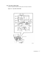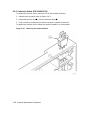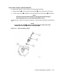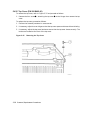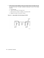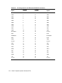
1
TSZ07 Tape Drive digi tal Technical Manual Order Number: EK–TSZ07–TM–003 TSZ07 Tape Drive Technical Manual Order Number: EK–TSZ07–TM–003 Prepared by Information Consulting and Design Digital Equipment Corporation • Merrimack, NH 03054 October 1992 The information in this document is subject to change without notice and should not be construed as a commitment by Digital Equipment Corporation. Digital Equipment Corporation assumes no responsibility for any errors that may appear in this document. No responsibility is assumed for the use or reliability of software on equipment that is not supplied by Digital Equipment Corporation or its affiliated companies. Restricted Rights: Use, duplication, or disclosure by the U.S. Government is subject to restrictions set forth in subparagraph (c)(1)(ii) of the Rights in Technical Data and Computer Software clause at DFARS 252.227-7013. Copyright ©Digital Equipment Corporation 1992 All Rights Reserved. Printed in U.S.A. CDA, DECUS, DDIF, DEC, DECimage, DECwindows, PDP, ThinWire, VAX, VMS, UNIBUS, and the DIGITAL logo are trademarks of Digital Equipment Corporation. Lubriplate® is a registered trademark of Fiske Brothers Refining Co. Loctite® is a registered trademark of Loctite Corporation. This document was prepared using VAX DOCUMENT, Version 2.1. Contents Preface xi Chapter 1 Introduction 1.1 1.2 1.3 1.4 General Description . . . . . . . . . . . . . . . . . . . . . . . . . . . . . . . . . . . . . . . . . . . . . . . . . . . . 1–1 Physical Description . . . . . . . . . . . . . . . . . . . . . . . . . . . . . . . . . . . . . . . . . . . . . . . . . . . . 1–4 1.2.1 Front View . . . . . . . . . . . . . . . . . . . . . . . . . . . . . . . . . . . . . . . . . . . . . . . . . . . . 1–5 1.2.2 Rear View . . . . . . . . . . . . . . . . . . . . . . . . . . . . . . . . . . . . . . . . . . . . . . . . . . . . 1–6 1.2.3 Top View of Deck Plate . . . . . . . . . . . . . . . . . . . . . . . . . . . . . . . . . . . . . . . . . . 1–7 1.2.4 Bottom View of Deck Plate . . . . . . . . . . . . . . . . . . . . . . . . . . . . . . . . . . . . . . . . 1–8 1.2.5 Major Circuit Board Assemblies . . . . . . . . . . . . . . . . . . . . . . . . . . . . . . . . . . . . 1–9 Functional Description . . . . . . . . . . . . . . . . . . . . . . . . . . . . . . . . . . . . . . . . . . . . . . . . . 1–10 1.3.1 Interface . . . . . . . . . . . . . . . . . . . . . . . . . . . . . . . . . . . . . . . . . . . . . . . . . . . . . 1–10 1.3.2 Electronics . . . . . . . . . . . . . . . . . . . . . . . . . . . . . . . . . . . . . . . . . . . . . . . . . . . 1–10 1.3.3 Servo Mechanism . . . . . . . . . . . . . . . . . . . . . . . . . . . . . . . . . . . . . . . . . . . . . . 1–11 Access Positions . . . . . . . . . . . . . . . . . . . . . . . . . . . . . . . . . . . . . . . . . . . . . . . . . . . . . . 1–11 Chapter 2 Operation 2.1 2.2 2.3 2.4 2.5 2.6 2.7 Controls and Indicators . . . . . . . . . . . . . . . . . . . . . . . . . . . . . . . . . . . . . . . . . . . . . . . . . 2–1 Density Selection . . . . . . . . . . . . . . . . . . . . . . . . . . . . . . . . . . . . . . . . . . . . . . . . . . . . . . 2–6 2.2.1 Power-Up Density Selection . . . . . . . . . . . . . . . . . . . . . . . . . . . . . . . . . . . . . . . 2–6 2.2.2 Host Density Selection . . . . . . . . . . . . . . . . . . . . . . . . . . . . . . . . . . . . . . . . . . . 2–6 2.2.3 Automatic Density Selection . . . . . . . . . . . . . . . . . . . . . . . . . . . . . . . . . . . . . . 2–6 2.2.4 Operator Density Selection . . . . . . . . . . . . . . . . . . . . . . . . . . . . . . . . . . . . . . . 2–6 Activity Messages . . . . . . . . . . . . . . . . . . . . . . . . . . . . . . . . . . . . . . . . . . . . . . . . . . . . . 2–7 Automatic Tape Loading . . . . . . . . . . . . . . . . . . . . . . . . . . . . . . . . . . . . . . . . . . . . . . . . 2–8 Manual Tape Loading . . . . . . . . . . . . . . . . . . . . . . . . . . . . . . . . . . . . . . . . . . . . . . . . . 2–10 Unloading Tape Automatically . . . . . . . . . . . . . . . . . . . . . . . . . . . . . . . . . . . . . . . . . . . 2–12 Unloading Tape Manually . . . . . . . . . . . . . . . . . . . . . . . . . . . . . . . . . . . . . . . . . . . . . . 2–12 iii Chapter 3 Maintenance 3.1 3.2 3.3 Tape Path . . . . . . . . . . . . . . . . . . . . . . . . . . . . . . . . . . . . . . . . . . . . . . . . . . . . . . . . . . . . 3–1 Sensors . . . . . . . . . . . . . . . . . . . . . . . . . . . . . . . . . . . . . . . . . . . . . . . . . . . . . . . . . . . . . 3–2 Air Filter . . . . . . . . . . . . . . . . . . . . . . . . . . . . . . . . . . . . . . . . . . . . . . . . . . . . . . . . . . . . 3–3 Chapter 4 Troubleshooting 4.1 4.2 4.3 4.4 4.5 Power-on Diagnostics . . . . . . . . . . . . . . . . . . . . . . . . . . . . . . . . . . . . . . . . . . . . . . . . . . . 4–1 Error Reporting . . . . . . . . . . . . . . . . . . . . . . . . . . . . . . . . . . . . . . . . . . . . . . . . . . . . . . . 4–2 Error Classification . . . . . . . . . . . . . . . . . . . . . . . . . . . . . . . . . . . . . . . . . . . . . . . . . . . . 4–2 4.3.1 Soft Error . . . . . . . . . . . . . . . . . . . . . . . . . . . . . . . . . . . . . . . . . . . . . . . . . . . . . 4–2 4.3.2 Medium Error . . . . . . . . . . . . . . . . . . . . . . . . . . . . . . . . . . . . . . . . . . . . . . . . . 4–2 4.3.3 Medium-Hard Error . . . . . . . . . . . . . . . . . . . . . . . . . . . . . . . . . . . . . . . . . . . . . 4–2 4.3.4 Hard Error . . . . . . . . . . . . . . . . . . . . . . . . . . . . . . . . . . . . . . . . . . . . . . . . . . . . 4–2 Fault Symptom Codes . . . . . . . . . . . . . . . . . . . . . . . . . . . . . . . . . . . . . . . . . . . . . . . . . . 4–3 Service Aids . . . . . . . . . . . . . . . . . . . . . . . . . . . . . . . . . . . . . . . . . . . . . . . . . . . . . . . . . . 4–9 4.5.1 Selecting Service Aids . . . . . . . . . . . . . . . . . . . . . . . . . . . . . . . . . . . . . . . . . . . 4–9 4.5.2 Tape-Unloaded Service Aids . . . . . . . . . . . . . . . . . . . . . . . . . . . . . . . . . . . . . . 4–10 4.5.2.1 Service Aid 111 (Servos) . . . . . . . . . . . . . . . . . . . . . . . . . . . . . . . . . . . 4–10 4.5.2.2 Service Aid 125 (Firmware ID) . . . . . . . . . . . . . . . . . . . . . . . . . . . . . 4–11 4.5.2.3 Service Aid 131 (Sensors) . . . . . . . . . . . . . . . . . . . . . . . . . . . . . . . . . . 4–12 4.5.2.4 Service Aid 132 (Solenoids) . . . . . . . . . . . . . . . . . . . . . . . . . . . . . . . . 4–12 4.5.2.5 Service Aid 134 (Blower) . . . . . . . . . . . . . . . . . . . . . . . . . . . . . . . . . . 4–13 4.5.2.6 Service Aid 142 (Configuration) . . . . . . . . . . . . . . . . . . . . . . . . . . . . . 4–13 4.5.3 Tape-Loaded Service Aids . . . . . . . . . . . . . . . . . . . . . . . . . . . . . . . . . . . . . . . 4–15 4.5.3.1 Service Aid 211 (Single-Pass Write/Read Check) . . . . . . . . . . . . . . . . 4–15 4.5.3.2 Service Aid 212 (Read/Write Data) . . . . . . . . . . . . . . . . . . . . . . . . . . . 4–17 4.5.3.3 Service Aid 222 (Tape Motion) . . . . . . . . . . . . . . . . . . . . . . . . . . . . . . 4–18 4.5.3.4 Service Aid 223 (Multi-Pass Write/Read Check) . . . . . . . . . . . . . . . . . 4–19 4.5.3.5 Service Aid 225 (Firmware ID) . . . . . . . . . . . . . . . . . . . . . . . . . . . . . 4–19 4.5.3.6 Service Aid 242 (Configuration) . . . . . . . . . . . . . . . . . . . . . . . . . . . . . 4–19 4.5.3.7 Service Aid 244 (Tape Read) . . . . . . . . . . . . . . . . . . . . . . . . . . . . . . . 4–19 4.5.4 Special Service Aids . . . . . . . . . . . . . . . . . . . . . . . . . . . . . . . . . . . . . . . . . . . . 4–21 4.5.4.1 Service Aid 513 (Head Calibration) . . . . . . . . . . . . . . . . . . . . . . . . . . 4–21 4.5.4.2 Service Aid 524 (Memory Initialization) . . . . . . . . . . . . . . . . . . . . . . . 4–21 4.5.4.3 Service Aid 525 (Motor Calibration) . . . . . . . . . . . . . . . . . . . . . . . . . . 4–22 4.5.4.4 Service Aid 533 (Door Lock and Interlock Disable) . . . . . . . . . . . . . . 4–22 4.5.4.5 Service Aid 542 (Vendor ID) . . . . . . . . . . . . . . . . . . . . . . . . . . . . . . . . 4–23 4.5.4.6 Service Aid 543 (Product ID) . . . . . . . . . . . . . . . . . . . . . . . . . . . . . . . 4–23 iv Chapter 5 Removal/Replacement Procedures 5.1 5.2 5.3 5.4 Tools and Materials . . . . . . . . . . . . . . . . . . . . . . . . . . . . . . . . . . . . . . . . . . . . . . . . . . . . 5–4 Opening the Tape Drive to the Operator Access Position . . . . . . . . . . . . . . . . . . . . . . . . 5–4 5.2.1 Operator Access for the Rack-Mount Drive . . . . . . . . . . . . . . . . . . . . . . . . . . . 5–4 5.2.2 Operator Access for the Table-Top Drive . . . . . . . . . . . . . . . . . . . . . . . . . . . . . 5–5 Opening the Tape Drive to the Service Access Position . . . . . . . . . . . . . . . . . . . . . . . . . 5–6 5.3.1 Service Access for the Rack-Mount Drive . . . . . . . . . . . . . . . . . . . . . . . . . . . . . 5–6 5.3.2 Service Access for the Table-Top Drive . . . . . . . . . . . . . . . . . . . . . . . . . . . . . . . 5–9 Removal/Replacement Procedures . . . . . . . . . . . . . . . . . . . . . . . . . . . . . . . . . . . . . . . . 5–10 5.4.1 Blower (P/N 29-28465-01) . . . . . . . . . . . . . . . . . . . . . . . . . . . . . . . . . . . . . . . 5–10 5.4.2 Control Switch Circuit Board (P/N 29-28463-01) . . . . . . . . . . . . . . . . . . . . . . 5–12 5.4.3 Front Door (P/N 29-28466-01) . . . . . . . . . . . . . . . . . . . . . . . . . . . . . . . . . . . . 5–13 5.4.4 Door Lock (P/N 29-28476-01) . . . . . . . . . . . . . . . . . . . . . . . . . . . . . . . . . . . . . 5–14 5.4.5 EOT/BOT Sensor Assembly (P/N 29-28649-01) . . . . . . . . . . . . . . . . . . . . . . . 5–15 5.4.6 File-Protect Sensor (P/N FD-11389-01) . . . . . . . . . . . . . . . . . . . . . . . . . . . . . . 5–16 5.4.7 Front Panel (P/N 29-28467-01) . . . . . . . . . . . . . . . . . . . . . . . . . . . . . . . . . . . . 5–17 5.4.8 Front Panel Display Circuit Board (P/N 29-28468-01) . . . . . . . . . . . . . . . . . . 5–18 5.4.9 Head Circuit Board (P/N 29-28478-01) . . . . . . . . . . . . . . . . . . . . . . . . . . . . . . 5–20 5.4.10 Hub Lock Solenoid (P/N 29-28475-01) . . . . . . . . . . . . . . . . . . . . . . . . . . . . . . 5–22 5.4.11 Input Air Duct . . . . . . . . . . . . . . . . . . . . . . . . . . . . . . . . . . . . . . . . . . . . . . . . 5–24 5.4.11.1 Removal Procedure Without Plenum Access Panel . . . . . . . . . . . . . . 5–24 5.4.11.2 Removal Procedure With Plenum Access Panel . . . . . . . . . . . . . . . . . 5–24 5.4.11.3 Replacing the Input Air Duct . . . . . . . . . . . . . . . . . . . . . . . . . . . . . . . 5–24 5.4.12 Interface Circuit Board (P/N 29-28477-01/29-30410-01) . . . . . . . . . . . . . . . . . 5–26 5.4.13 Interlock Switch (P/N 29-28476-02) . . . . . . . . . . . . . . . . . . . . . . . . . . . . . . . . 5–28 5.4.14 Left Output Air Duct . . . . . . . . . . . . . . . . . . . . . . . . . . . . . . . . . . . . . . . . . . . 5–29 5.4.15 Manual Release Switch . . . . . . . . . . . . . . . . . . . . . . . . . . . . . . . . . . . . . . . . . 5–30 5.4.16 Packer Arm . . . . . . . . . . . . . . . . . . . . . . . . . . . . . . . . . . . . . . . . . . . . . . . . . . 5–31 5.4.17 Plenum (P/N 29-28482-01) . . . . . . . . . . . . . . . . . . . . . . . . . . . . . . . . . . . . . . . 5–32 5.4.18 Power Supply (P/N 29-28461-01) . . . . . . . . . . . . . . . . . . . . . . . . . . . . . . . . . . 5–34 5.4.19 Read/Write Formatter Circuit Board (P/N 29-28480-01) . . . . . . . . . . . . . . . . . 5–36 5.4.20 Read/Write Head (P/N 29-28472-01) . . . . . . . . . . . . . . . . . . . . . . . . . . . . . . . . 5–38 5.4.21 Right Output Air Duct . . . . . . . . . . . . . . . . . . . . . . . . . . . . . . . . . . . . . . . . . . 5–39 5.4.22 Roller Guide 1 (P/N 29-24101-00) . . . . . . . . . . . . . . . . . . . . . . . . . . . . . . . . . . 5–41 5.4.23 Roller Guide 2 . . . . . . . . . . . . . . . . . . . . . . . . . . . . . . . . . . . . . . . . . . . . . . . . 5–42 5.4.24 Roller Guide 3 or 4 (P/N 29-24081-00) . . . . . . . . . . . . . . . . . . . . . . . . . . . . . . 5–42 5.4.25 Roller Guide 5 (P/N 29-24081-00) . . . . . . . . . . . . . . . . . . . . . . . . . . . . . . . . . . 5–43 5.4.26 Servo Circuit Board (P/N 29-28479-01) . . . . . . . . . . . . . . . . . . . . . . . . . . . . . 5–44 5.4.27 Supply Hub (P/N 29-24077-00) . . . . . . . . . . . . . . . . . . . . . . . . . . . . . . . . . . . . 5–46 5.4.28 Supply Hub Bell Crank . . . . . . . . . . . . . . . . . . . . . . . . . . . . . . . . . . . . . . . . . 5–47 5.4.29 Supply Motor (P/N 29-28470-01) . . . . . . . . . . . . . . . . . . . . . . . . . . . . . . . . . . 5–48 v 5.4.30 5.4.31 5.4.32 5.4.33 5.4.34 5.4.35 Take-Up Hub . . . . . . . . . . . . . . . . . . . . . . . . . . . . Take-Up Motor (P/N 29-28469-01) . . . . . . . . . . . . Tape-In-Path Receiver (P/N 29-24093-00) . . . . . . . Tape-In-Path Transmitter (P/N 29-28483-01) . . . . Tension Sensor/Roller Guide 2 (P/N 29-28471-01) Top Cover (P/N 29-28462-01) . . . . . . . . . . . . . . . . . . . . . . . . . . . . . . . . . . . . . . . . . . . . . . . . . . . . . . . . . . . . . . . . . . . . . . . . . . . . . . . . . . . . . . . . . . . . . . . . . . . . . . . . . . . . . . . . . . . . . . . . . . . . . . . . . . . . . . . . . . . . . . 5–50 5–52 5–54 5–55 5–56 5–58 . . . . . . . . . . . . . . . . . . . . . . . . . . . . . . . . . . . . . . . . . . . . . . . . . . . . . . . . . . . . . . . . . . . . . . . . . . . . . . . . . . . . . . . . . . . . . . . . . . . . . . . . . . . . . . . . . . . . . . . . . . . . . . . 6–2 . 6–4 . 6–4 . 6–7 . 6–9 6–11 Introduction . . . . . . . . . . . . . . . . . . . . . . . . . . . . . . . . . . . . . . . . . . . . . . . . . . . . . . . . . Signals . . . . . . . . . . . . . . . . . . . . . . . . . . . . . . . . . . . . . . . . . . . . . . . . . . . . . . . . . . . . . SCSI Bus Phases . . . . . . . . . . . . . . . . . . . . . . . . . . . . . . . . . . . . . . . . . . . . . . . . . . . . . SCSI Bus Conditions . . . . . . . . . . . . . . . . . . . . . . . . . . . . . . . . . . . . . . . . . . . . . . . . . . B.4.1 Attention Condition . . . . . . . . . . . . . . . . . . . . . . . . . . . . . . . . . . . . . . . . . . . . B.4.2 Reset Condition . . . . . . . . . . . . . . . . . . . . . . . . . . . . . . . . . . . . . . . . . . . . . . . SCSI Message System . . . . . . . . . . . . . . . . . . . . . . . . . . . . . . . . . . . . . . . . . . . . . . . . . B.5.1 Messages — Format and Codes . . . . . . . . . . . . . . . . . . . . . . . . . . . . . . . . . . . B.5.2 Messages . . . . . . . . . . . . . . . . . . . . . . . . . . . . . . . . . . . . . . . . . . . . . . . . . . . . Status . . . . . . . . . . . . . . . . . . . . . . . . . . . . . . . . . . . . . . . . . . . . . . . . . . . . . . . . . . . . . Commands . . . . . . . . . . . . . . . . . . . . . . . . . . . . . . . . . . . . . . . . . . . . . . . . . . . . . . . . . . B–1 B–1 B–5 B–5 B–5 B–5 B–6 B–6 B–7 B–8 B–9 Chapter 6 Adjustment Procedures 6.1 6.2 6.3 6.4 6.5 6.6 Interlock Switch Disable Procedure Read Threshold Adjustment . . . . . . Skew Adjustment . . . . . . . . . . . . . . Supply Hub Adjustment . . . . . . . . . Take-Up Hub Adjustment . . . . . . . Operation Verification . . . . . . . . . . . . . . . . . . . . . . . . . . . . . . . . . . . . . . . . . . . . . . . . . . . . . . . . . . . . . . . . . . . . . . . . . . . . . . . . . . . . . . . . . . . . . . . . . . . . . . . . . . . . . . . . . . . . . . Appendix A Specifications Appendix B Small Computer System Interface (SCSI) B.1 B.2 B.3 B.4 B.5 B.6 B.7 Figures 1–1 1–2 1–3 1–4 1–5 1–6 2–1 TSZ07 Tape Drive Versions . . . . Front Parts . . . . . . . . . . . . . . . . Rear Parts . . . . . . . . . . . . . . . . . Top Parts of Deck Plate . . . . . . . Bottom Parts of Deck Plate . . . . Major Circuit Board Assemblies . TSZ07 Controls and Indicators . . . . . . . . . . . . . . . vi . . . . . . . . . . . . . . . . . . . . . . . . . . . . . . . . . . . . . . . . . . . . . . . . . . . . . . . . . . . . . . . . . . . . . . . . . . . . . . . . . . . . . . . . . . . . . . . . . . . . . . . . . . . . . . . . . . . . . . . . . . . . . . . . . . . . . . . . . . . . . . . . . . . . . . . . . . . . . . . . . . . . . . . . . . . . . . . . . . . . . . . . . . . . . . . . . . . . . . . . . . . . . . . . . . . . . . . . . . . . . . . . . . . . . . . . 1–2 . 1–5 . 1–6 . 1–7 . 1–8 . 1–9 . 2–5 2–2 2–3 2–4 3–1 3–2 4–1 5–1 5–2 5–3 5–4 5–5 5–6 5–7 5–8 5–9 5–10 5–11 5–12 5–13 5–14 5–15 5–16 5–17 5–18 5–19 5–20 5–21 5–22 5–23 5–24 5–25 5–26 5–27 5–28 5–29 5–30 5–31 5–32 5–33 5–34 5–35 5–36 Write-Enable Ring . . . . . . . . . . . . . . . . . . . . . . . . . Tape Reel Insertion . . . . . . . . . . . . . . . . . . . . . . . . TSZ07 Tape Path . . . . . . . . . . . . . . . . . . . . . . . . . . Location of Tape Path and Sensors . . . . . . . . . . . . Location of Air Filter . . . . . . . . . . . . . . . . . . . . . . . Assigned Numbers of Control Panel Switches . . . . Operator Access Position . . . . . . . . . . . . . . . . . . . . Location of Retaining Screws . . . . . . . . . . . . . . . . . Service Access Position . . . . . . . . . . . . . . . . . . . . . Removing the Blower . . . . . . . . . . . . . . . . . . . . . . . Removing the Control Switch Circuit Board . . . . . Removing the Door . . . . . . . . . . . . . . . . . . . . . . . . . Removing the Door Lock . . . . . . . . . . . . . . . . . . . . Removing the EOT/BOT Sensor Assembly . . . . . . . Removing the File-Protect Sensor . . . . . . . . . . . . . Removing the Front Panel . . . . . . . . . . . . . . . . . . . Removing the Front Panel Display Circuit Board . Removing the Head Circuit Board . . . . . . . . . . . . . Removing the Hub Lock Solenoid . . . . . . . . . . . . . . Removing the Input Air Duct . . . . . . . . . . . . . . . . . Removing the Interface Circuit Board . . . . . . . . . . Removing the Interlock Switch . . . . . . . . . . . . . . . Removing the Left Output Air Duct . . . . . . . . . . . . Removing the Manual Release Switch . . . . . . . . . . Removing the Packer Arm . . . . . . . . . . . . . . . . . . . Removing the Plenum . . . . . . . . . . . . . . . . . . . . . . Removing the Power Supply . . . . . . . . . . . . . . . . . Removing the Read/Write Formatter Circuit Board Removing the Read/Write Head . . . . . . . . . . . . . . . Removing the Right Output Air Duct . . . . . . . . . . Removing Roller Guide 1 . . . . . . . . . . . . . . . . . . . . Removing Roller Guide 3 or 4 . . . . . . . . . . . . . . . . Removing Roller Guide 5 . . . . . . . . . . . . . . . . . . . . Removing the Servo Circuit Board . . . . . . . . . . . . . Removing the Supply Hub . . . . . . . . . . . . . . . . . . . Removing the Supply Hub Bell Crank . . . . . . . . . . Removing the Supply Motor . . . . . . . . . . . . . . . . . . Removing the Take-Up Hub . . . . . . . . . . . . . . . . . . Removing the Take-Up Motor . . . . . . . . . . . . . . . . Removing the Tape-in-Path Receiver . . . . . . . . . . . Removing the Tape-in-Path Transmitter . . . . . . . . Removing Tension Sensor/Roller Guide 2 . . . . . . . . vii . . . . . . . . . . . . . . . . . . . . . . . . . . . . . . . . . . . . . . . . . . . . . . . . . . . . . . . . . . . . . . . . . . . . . . . . . . . . . . . . . . . . . . . . . . . . . . . . . . . . . . . . . . . . . . . . . . . . . . . . . . . . . . . . . . . . . . . . . . . . . . . . . . . . . . . . . . . . . . . . . . . . . . . . . . . . . . . . . . . . . . . . . . . . . . . . . . . . . . . . . . . . . . . . . . . . . . . . . . . . . . . . . . . . . . . . . . . . . . . . . . . . . . . . . . . . . . . . . . . . . . . . . . . . . . . . . . . . . . . . . . . . . . . . . . . . . . . . . . . . . . . . . . . . . . . . . . . . . . . . . . . . . . . . . . . . . . . . . . . . . . . . . . . . . . . . . . . . . . . . . . . . . . . . . . . . . . . . . . . . . . . . . . . . . . . . . . . . . . . . . . . . . . . . . . . . . . . . . . . . . . . . . . . . . . . . . . . . . . . . . . . . . . . . . . . . . . . . . . . . . . . . . . . . . . . . . . . . . . . . . . . . . . . . . . . . . . . . . . . . . . . . . . . . . . . . . . . . . . . . . . . . . . . . . . . . . . . . . . . . . . . . . . . . . . . . . . . . . . . . . . . . . . . . . . . . . . . . . . . . . . . . . . . . . . . . . . . . . . . . . . . . . . . . . . . . . . . . . . . . . . . . . . . . . . . . . . . . . . . . . . . . . . . . . . . . . . . . . . . . . . . . . . . . . . . . . . . . . . . . . . . . . . . . . . . . . . . . . . . . . . . . . . . . . . . . . . . . . . . . . . . . . . . . . . . . . . . . . . . . . . . . . . . . . . . . . . . . . . . . . . . . . . . . . . . . . . . . . . . . . . . . . . . . . . . . . . . . . . . . . . . . . . . . . . . . . . . . . . . . . . . . . . . . . . . . . . . . . . . . . . . . . . . . . . . . . . . . . . . . . . . . . . . . . . . . . . . . . . . . . . . 2–8 . 2–9 2–11 . 3–2 . 3–3 . 4–9 . 5–5 . 5–7 . 5–8 5–11 5–12 5–13 5–14 5–15 5–16 5–17 5–19 5–21 5–23 5–25 5–27 5–28 5–29 5–30 5–31 5–33 5–35 5–37 5–38 5–40 5–41 5–42 5–43 5–45 5–46 5–47 5–49 5–51 5–53 5–54 5–55 5–57 5–37 6–1 6–2 6–3 6–4 6–5 6–6 Removing the Top Cover . . . . . . . . . . . . . . . . Location of Interlock Switch . . . . . . . . . . . . . . Location of Skew Adjustment Screw . . . . . . . Skew Adjustment Waveform . . . . . . . . . . . . . Location of Supply Hub Screws . . . . . . . . . . . Aligning Motor Shaft with Supply Hub Dwell Adjusting the Take-Up Hub . . . . . . . . . . . . . . . . . . . . . . . . . . . . . . . . . . . . . . . . . . . . . . . . . . . . . . . . . . . . . . . . . . . . . . . . . . . . . . . . . . . . . . . . . . . . . . . . . . . . . . . . . . . . . . . . . . . . . . . . . . . . . . . . . . . . . . . . . . . . . . . . . . . . . . . . . . . . . . . . . . . . . . . . . . . . . . . . . . . . . . . . . . . . . 5–58 . 6–3 . 6–5 . 6–6 . 6–7 . 6–8 6–10 Tables 1–1 2–1 2–2 4–1 4–2 4–3 4–4 4–5 4–6 4–7 4–8 4–9 4–10 4–11 4–12 4–13 4–14 4–15 4–16 4–17 4–18 4–19 4–20 4–21 4–22 4–23 5–1 5–2 A–1 B–1 B–2 B–3 B–4 TSZ07 Tape Drive Versions . . . . . . . . . . . . . . . . . . . . . . . . . . . . . . . . . . . . . . . . 1–3 TSZ07 Controls and Indicators . . . . . . . . . . . . . . . . . . . . . . . . . . . . . . . . . . . . . 2–2 Operating Messages . . . . . . . . . . . . . . . . . . . . . . . . . . . . . . . . . . . . . . . . . . . . . . 2–7 Fault System Codes (FSC) with Related FM, ERPs and FRUs . . . . . . . . . . . . . 4–3 Fault Messages (FM) . . . . . . . . . . . . . . . . . . . . . . . . . . . . . . . . . . . . . . . . . . . . . 4–6 Error Recovery Procedure (ERP) . . . . . . . . . . . . . . . . . . . . . . . . . . . . . . . . . . . . 4–7 Field Replaceable Units (FRU) . . . . . . . . . . . . . . . . . . . . . . . . . . . . . . . . . . . . . . 4–8 Service Aid 111 Test Selection . . . . . . . . . . . . . . . . . . . . . . . . . . . . . . . . . . . . . 4–10 Service Aid 111 Switch Functions . . . . . . . . . . . . . . . . . . . . . . . . . . . . . . . . . . 4–11 Service Aid 125 Front Panel Switches . . . . . . . . . . . . . . . . . . . . . . . . . . . . . . . 4–12 Front Panel Switch Functions in Review Mode . . . . . . . . . . . . . . . . . . . . . . . . 4–13 Front Panel Switch Functions in Change Mode . . . . . . . . . . . . . . . . . . . . . . . . 4–13 TSZ07 Configuration Parameters . . . . . . . . . . . . . . . . . . . . . . . . . . . . . . . . . . . 4–14 Switch Functions in the Execution Mode . . . . . . . . . . . . . . . . . . . . . . . . . . . . . 4–16 Front Panel Switch Functions in the Status Mode . . . . . . . . . . . . . . . . . . . . . . 4–16 Error Messages . . . . . . . . . . . . . . . . . . . . . . . . . . . . . . . . . . . . . . . . . . . . . . . . 4–17 Service Aid 212 Front Panel Switches . . . . . . . . . . . . . . . . . . . . . . . . . . . . . . . 4–18 Front Panel Switch Function in the Selection Mode . . . . . . . . . . . . . . . . . . . . 4–18 Front Panel Switch Functions in the Robot Mode . . . . . . . . . . . . . . . . . . . . . . 4–18 Front Panel Switch Functions in the Read Mode . . . . . . . . . . . . . . . . . . . . . . . 4–19 Front Panel Switch Functions in the Status Mode . . . . . . . . . . . . . . . . . . . . . . 4–20 Error Messages . . . . . . . . . . . . . . . . . . . . . . . . . . . . . . . . . . . . . . . . . . . . . . . . 4–20 Front Panel Switch Functions During Service Aid 524 . . . . . . . . . . . . . . . . . . 4–22 Front Panel Switch Functions during Service Aid 525 . . . . . . . . . . . . . . . . . . . 4–22 Front Panel Switch Functions during Service Aid 542 . . . . . . . . . . . . . . . . . . . 4–23 Front Panel Switch Functions during Service Aid 543 . . . . . . . . . . . . . . . . . . . 4–23 TSZ07 FRUs . . . . . . . . . . . . . . . . . . . . . . . . . . . . . . . . . . . . . . . . . . . . . . . . . . . 5–2 Special Tools and Materials . . . . . . . . . . . . . . . . . . . . . . . . . . . . . . . . . . . . . . . . 5–4 TSZ07 Specifications . . . . . . . . . . . . . . . . . . . . . . . . . . . . . . . . . . . . . . . . . . . . A–1 SCSI Bus Signals . . . . . . . . . . . . . . . . . . . . . . . . . . . . . . . . . . . . . . . . . . . . . . . B–2 Pin Assignments for the Single-Ended Shielded Connections . . . . . . . . . . . . . B–3 Pin Assignment for the Differential Shielded Connections . . . . . . . . . . . . . . . . B–4 SCSI Bus Phases . . . . . . . . . . . . . . . . . . . . . . . . . . . . . . . . . . . . . . . . . . . . . . . B–5 viii B–5 B–6 B–7 B–8 Messages — Format and Codes SCSI Messages . . . . . . . . . . . . . Status Bytes . . . . . . . . . . . . . . . TSZ07 SCSI Commands . . . . . . . . . . . . . . . . . . ix . . . . . . . . . . . . . . . . . . . . . . . . . . . . . . . . . . . . . . . . . . . . . . . . . . . . . . . . . . . . . . . . . . . . . . . . . . . . . . . . . . . . . . . . . . . . . . . . . . . . . . . . . . . . . . . . . . . . . . . . . . . . . . . . . . . . B–6 B–7 B–8 B–9 Preface This manual provides the information necessary to troubleshoot, and repair the TSZ07 Tape Drive. Programming information concerning the Small Computer System Interface (SCSI) used in the TSZ07 is also provided. Throughout this manual the TSZ07 Tape Drive will be referred to as either the TSZ07 or the drive. Structure of this Manual This manual is structured as follows: Chapter 1, Introduction — Provides a general, physical and functional description of the TSZ07 Tape Drive. Chapter 2, Operation — Describes the controls and indicators and describes how to load and unload tape. Chapter 3, Maintenance — Describes how to perform the required tape drive preventive maintenance, which is limited to regular cleaning of the tape path, sensors, and air filter. Chapter 4, Troubleshooting — Describes the self-diagnostic and troubleshooting capabilities designed in the tape drive; how tape processing errors and tape drive faults are reported; and how to use service aids resident in the firmware of the drive. This chapter also provides a list of the error recovery procedures. Chapter 5, Removal/Replacement Procedures — Provides the removal/replacement procedures for various components and assemblies of the tape drive with references to service aids and the appropriate adjustment procedures when necessary. The procedures are for use by qualified service personnel familiar with the drive unit. Chapter 6, Adjustments — Provides the adjustment procedures, purpose of the adjustments and when they should be used. Appendix A, Specifications — Provides the specifications for the TSZ07 Tape Drive. Appendix B, Small Computer System Interface (SCSI) — Describes the SCSI 2 and the associated control signals, messages, status bytes and commands. xi Related Documents The following are publications that support the TSZ07 Tape Drive: • TSZ07 Tape Drive Installation/Owner’s Manual (EK-TSZ07-IN) • TSZ07 Tape Drive Pocket Service Guide (EK-TSZ07-PG) • Small Computer System Interface: An Overview (EK-SCSIS-OV) • Small Computer System Interface: A Developer’s guide (EK-SCSIS-DK) • KZQSA Module Installation Guide (EK-KZQSA-IG) • H9642 Cabinet Maintenance Guide (EK-187AA-MG) • Field Maintenance Print Set (MP-03190-01) • MicroVAX Diagnostic Monitor User’s Guide (AA-FM7AE-DN) Notes, Cautions, and Warnings Where notes, cautions, and warnings are used in this document, specific types of information are highlighted as follows: NOTE — Calls the attention to any item of information that may be of special importance to the reader. CAUTION — Contains essential information to avoid damage to the equipment. WARNING — Contains essential information for the safety of the user. xii FCC USER STATEMENT NOTICE: This equipment generates, uses, and may emit radio frequency. The equipment has been type tested and found to comply with the limits for a Class A digital device pursuant to Part 15 of FCC rules, which are designed to provide reasonable protection against such radio frequency interference. Operation of this equipment in a residential area may cause interference in which case the user at his own expense will be required to take whatever measures may be required to correct the interference. xiii Für Bundesrepublik Deutschland end Berlin (West) For Federal Republic of Germany end West Berlin Pour la République féderale d’Allemagne et Berlin Ouest Hochfrequenzgerätezulassung end Betriebsgenehmigung Bescheinigung des Herstellers/Importeurs Hiermit wird bescheinigt, daß die Einrichtung in Übereinstimmung mit den Bestimmungen der DBP-Verfügung 523/1969, Amtsblatt 113/1969, end Grenzwertklasse "A" der VDE0871, funkentstört ist. Das Zentralamt für Zulassungen im Fernmeldewesen der Deutschen Bundespost (DBP), hat diesem Gerät eine FTZ-Serienprüfnummer zugeteilt. Betriebsgenehmigung Hochfrequenzgeräte dürfen erst in Betrieb genommen werden, nachdem hiefür von dem für den vorgesehenen Aufstellungsort zuständigen Fernmeldeamt mit Funkstörungsmeßstelle die Genehmigung erteilt ist. Als Antrag auf Erteilung einer Genehmigung dient eine Anmeldepostkarte (Anhang des Handbuches) mit Angabe der FTZSerienprüfnummer. Der untere Teil der Postkarte ist vom Betreiber zu vervollständigen end an das örtliche Fernmeldeamt zu schicken. Der obere Teil bleibt beim Gerät. Betreiberhinweis Das Gerät wurde funktechnisch sorgfältig entstört end geprüft. Die Kennzeichnung mit der Zulassungsnummer bietet Ihnen die Gewähr, daß dieses Gerät keine anderen Fernmeldeanlagen einschließlich Funkanlagen stört. Sollten bei diesen Geräten ausnahmsweise trotzdem, z.B. im ungünstigsten Fall beim Zusammenschalten mit anderen EDVGeräten, Funkstörungen auftreten kann das im Einzelnen zusätzliche Funkenstörungsmaßnahmen durch den Benutzer erfordern. Bei Fragen hierzu wenden Sie sich bitte an die örtlich zuständige Funkstörungsmeßstelle Ihres Fernmeldeamtes. Externe Datenkabel Sollte ein Austausch der von Digital spezifizierten Datenkabel nötig werden, muß der Betreiber für eine einwandfreie Funkentstörung sicherstellen, daß Austauschkabel im Aufbau end Abschirmqualität dem Digital Originalkabel entsprechen. Kennzeichnung Die Geräte werden bereits in der Fertigung mit der Zulassungsnummer gekennzeichnet end mit einer Anmeldepostkarte versehen. Sollte Kennzeichnung end Anmeldepostkarte übergangsweise nicht mit ausgeliefert werden kontaktieren Sie bitte das nächstgelegene Digital Equipment Kundendienstbüro. xiv Chapter 1 Introduction This chapter provides general, physical, and functional descriptions of the TSZ07 Tape Drive and provides illustrations showing the major parts of the drive. 1.1 General Description The TSZ07 Tape Drive (shown in Figure 1–1) is a high-capacity streaming, nine-track, reelto-reel, half-inch magnetic tape drive unit with the capability of reading or writing in one of two selectable recording densities. The drive is designed for the interchanging of data, archival storage, software distribution, online transaction management, and the backup of small and large computing systems. Connection to external computer equipment is by way of an onboard Small Computer System Interface (SCSI 2) which conforms to the American National Standard Institute (ANSI) specification X3T9.2/89-042. The TSZ07 Tape Drive comes with either a single-ended or differential-ended SCSI interface (see to Table 1–1). Single-ended drives allow a total SCSI bus length of 6 meters; differential-ended drives allow a total SCSI bus length of 25 meters. Introduction 1–1 Figure 1–1: TSZ07 Tape Drive Versions 1–2 Introduction There are four versions of the TSZ07 Tape Drive as described in Table 1–1. Table 1–1: TSZ07 Tape Drive Versions Description Order Number Rackmount unit without power cord. Customer must order the correct country kit to obtain power cord. Single-ended SCSI. TSZ07-AA Rackmount unit installed in a Digital 40-inch high H9642 style cabinet with an 874-D, 120 Volt, 24 Ampere, Filtered Power Controller. Singleended SCSI. TSZ07-BA Rackmount unit installed in a Digital 40-inch high H9642 style cabinet with an 874-F, 240 Volt, 12 Ampere, Filtered Power Controller. Power cord for the power controller must be ordered separately. Single-ended SCSI. TSZ07-BB Table-top unit without power cord. Customer must order the correct country kit to obtain power cord. Single-ended SCSI. TSZ07-CA SCSI interface magtape, rackmountable reel to reel, 1600/6250 bits/in. Differential-ended SCSI. TSZ07-DA SCSI magtape in H9642 cabinet with 874D, 120-Volt Power Controller. Differential-ended SCSI. TSZ07-EA SCSI magtape in H9642 cabinet with 874F, 240-Volt Power Controller. Differential-ended SCSI. TSZ07-EB SCSI interface magtape, table-top, reel to reel, 1600/6250. Differentialended SCSI. TSZ07-FA The table-top unit (TSZ07-CA/FA) is suitable for an open office environment that conforms to the environmental limits stated in Appendix A. The rackmount unit (TSZ07-AA/DA) is suitable for either a computer room or a manufacturing location. The Digital cabinet versions (TSZ07-BA/EA or TSZ07-BB/EB) may be used in the same type environment as specified for either the table-top or rackmount unit. Details covering the installation of the drive are provided in the TSZ07 Tape Drive Installation/Owner’s Manual. The TSZ07 reads and writes data at 100 inches per second (ips) in either the Phase Encoding (PE) format at 1600 bits per inch (bpi) or the Group Code Recording format at 6250 bpi. The drive uses industry-standard 0.5-inch wide tape with any of four reel sizes, 6.0, 7.0, 8.5, and 10.5 inches. The three larger tape reel sizes are auto-loaded by the TSZ07. The 6-inch reel size does not have the same tape loading characteristics. Manual loading may be required depending on the amount of tape on the 6-inch reel. Greater than 300 feet of tape is required for auto-loading to be achieved with a high degree of confidence. Introduction 1–3 Communication to the drive is by way of the SCSI 2 interface at a synchronous rate of 4 Megabytes (1.5 Megabytes asynchronous) per second. The standard features of the drive include: • Mounting in standard 19-inch EIA/RETMA † rack (rackmount version) • Automatic tape loading and threading • Drive parameters configurable from the front panel • Eight-character alphanumeric display on the front panel • Automatic read/write retry • Autoranging ac power supply 1.2 Physical Description The three main physical assemblies of the drive are: • front panel • deck plate • chassis The front panel is fastened to the deck plate. The front panel has a door that opens to allow easy operator access for loading and unloading the magnetic tape. Beneath the door are operator switches, indicators, and an eight-character alphanumeric display. Air inlets in the front panel provide for cooling and automatic tape loading. The deck plate is made of cast-aluminum and supports two dc motors, tape path sensors, and a read/write head. The deck plate is hinged to the sheet metal chassis. The chassis forms a box-like structure to protect the internal circuit boards and components. Power and system interface connections are made at the back of the chassis. The drive is designed for rack mounting, and is compatible with cabinets meeting the standard 19-inch EIA/RETMA form factor. A table-top enclosure is also available for the drive. For the location of the major mechanical parts and electronic circuit board assemblies, refer to Section 1.2.1 through Section 1.2.5. † RETMA racks are standard sized cabinets used by Digital and other major manufacturers of electronic equipment. The cabinet rails, mounting hole patterns, and spacing conform to international standards that allow compatibility with products manufactured by Digital and other major manufacturers. 1–4 Introduction 1.2.1 Front View Figure 1–2 shows the location of parts accessible from the front of the tape drive. Figure 1–2: Front Parts Introduction 1–5 1.2.2 Rear View Figure 1–3 shows the location of the major parts at the rear of the drive. Figure 1–3: Rear Parts 1–6 Introduction 1.2.3 Top View of Deck Plate Figure 1–4 shows the location of major parts at the top of the drive. Figure 1–4: Top Parts of Deck Plate Introduction 1–7 1.2.4 Bottom View of Deck Plate Figure 1–5 shows the location of the major parts at the bottom of the deck plate. Figure 1–5: Bottom Parts of Deck Plate 1–8 Introduction 1.2.5 Major Circuit Board Assemblies Figure 1–6 shows the location of the major circuit board assemblies in the TSZ07. Figure 1–6: Major Circuit Board Assemblies Introduction 1–9 1.3 Functional Description The drive is designed to stream in a start/stop environment using standard start/stop software. It uses an internal one-megabyte cache memory as an electronic tape buffer that decouples the physical and logical tape operations. The primary function of the cache memory is to provide higher performance on systems that are not able to stream. The drive has three main functional assemblies: the interface, the electronics, and the servo mechanism. These assemblies interact to accomplish the various functions performed by the drive. 1.3.1 Interface The SCSI 2 interface translates bus commands into tape-drive-executable commands. The interface also translates tape drive data and status signals into the correct bus format. 1.3.2 Electronics A Z8002 microprocessor controls all necessary logic functions relating to read/write, servo control, cache memory, and the transfer of data and commands in the drive. An 80188 microprocessor operates in synchronous with the Z8002 control communications with the external SCSI bus. The SCSI bus transmits data to the TSZ07, which writes it on the tape with the PE and GCR recording methods at 1600 and 6250 bpi. Nine tracks (8 data, 1 parity) are written simultaneously across the width of the tape. The TSZ07 reads recorded data from the tape and transfers it to the SCSI bus. To perform this function, a microprocessor interprets commands from the interface; accelerates and decelerates the tape; positions it at the read/write head; controls formatting; and provides status to the host. The TSZ07 is self-loading. The user inserts a reel of tape into the front panel opening, and presses the LOAD switch. Then, the drive automatically threads the tape around the tension sensor, across the read/write head, and around the take-up hub. Finally, the drive tensions the tape, and positions the tape at the Beginning of Tape (BOT) . The drive has automatic error recovery capability. Errors detected during a write operation result in the tape being automatically backspaced, erased, and the data rewritten on a faultfree section of tape. The drive corrects read errors "on the fly" for up to two tracks in GCR and one track in PE. The drive automatically backspaces and retries multi-track read errors that are not correctable. Standard features of the drive electronics include: • Configuration parameters stored in non-volatile memory • One megabyte of cache memory • Custom analog read amplifier chip for each track • Extensive use of large scale integration (LSI) and surface mount technology • Solid-state tension transducer 1–10 Introduction 1.3.3 Servo Mechanism The mechanical assemblies of the drive are managed by the microprocessor. These assemblies control tape loading and unloading and maintain correct tape tension. The drive mechanism uses two direct-drive DC torque motors, a tachometer assembly that senses tape speed and position, and a servo-drive that eliminates the need for a capstan. Tape movement is controlled primarily by the take-up servo and the tachometer. The tape path has five roller guides, a dual-gap head, and a tape cleaner. The roller guides, positioned on each side of the head, are designed to minimize friction, skew, and tape-width variations. Standard features of the drive mechanism include: • Unbuffered tape path • Velocity tachometers mounted on motors • Brushless dc blower motor for loading and cooling 1.4 Access Positions There are two ways of gaining access to the drive: • The operator access position, which provides operator access to the tape path • The service access position, which provides field service access to the internal electronic and mechanical parts of the drive Throughout this manual it is expected that the reader is a trained, qualified technician who is familiar with both ways of accessing the drive. Accessing the tape drive is described in Chapter 5. Introduction 1–11 Chapter 2 Operation This chapter defines the use of all controls and indicators of the TSZ07 and explains how to load and unload tapes. 2.1 Controls and Indicators The controls and indicators are described in Table 2–1 and shown in Figure 2–1. NOTE The function of the front panel controls and indicators described in Table 2–1 is for normal operation. The control panel is also used in selecting service aids for configuring the drive, testing various Field Replaceable Units (FRUs) and troubleshooting. For details on the service aids and how to use the control panel in the service aid mode of operation, refer to Chapter 4. Operation 2–1 Table 2–1: TSZ07 Controls and Indicators Item Function AC Power Switch Located at the rear of the drive (not shown in Figure 2–1). When set to the on (1) position, ac power is applied to the tape drive power supply. When set to off (0), ac power is disconnected from the power supply. This switch must be on to operate the drive. CAUTION Once the drive is installed and running on a host system, setting the switch to off (0) may interrupt the normal operation of the system. When ac power is applied to the power supply, the drive initializes, causing the following to occur: 1. 2. 3. 4. Load Rewind, Unload, Online, Wrt En Test, and Density Select indicators flash and TESTING appears on the display. TESTING changes to TESTPASS and the indicators continue to flash. Indicators extinguish. Display goes blank, then the Unload and On/Off indicators light showing that the tape drive is ready for loading tape operation. Front Door When opened, provides access to the supply hub for the insertion or removal of a reel of tape. Also provides access to the manual release switch. The front door must be closed for operation. Manual Release Switch When pressed, engages/retracts the supply hub pawls to enable the loading /unloading of a reel of tape. Used when performing the procedure for manually loading/unloading a reel of tape. Load Rewind Indicator When flashing, indicates a tape is being loaded. Unload Indicator When flashing, indicates that a tape is being unloaded. When lit, indicates that a tape is unloaded. When not lit, indicates that there is no tape loaded in the drive. Online Indicator When lit, indicates the drive is on line. When extinguished, the drive is off line. Wrt En Test Indicator When lit, indicates that the loaded tape has a write-enable ring. Density Select Indicator Flashes along with all other indicators during initialization, when the AC Power Switch or ON/OFF Switch is set to on. Alphanumeric Display Displays status and error messages during normal operation and while in the service aid mode as described in Chapter 4. On/Off Indicator When lit, indicates that dc power is applied to the drive circuits and that the drive is ready to operate. When not lit, indicates that the dc power is disconnected. 2–2 Operation Table 2–1 (Cont.): TSZ07 Controls and Indicators Item Function ON/OFF Switch When pressed once, connects dc power throughout the drive and lights the On/Off indicator. When pressed again, disconnects dc power and turns off the indicator. CAUTION Once the drive is installed and running on a host system, operating this switch may interrupt the normal operation of that system. When set to on, the drive initializes causing the following to occur: 1. 2. 3. 4. DENSITY SELECT Switch Load Rewind, Unload, Online, Wrt En Test, and Density Select indicators flash and TESTING appears in the display. TESTING changes to TESTPASS and the indicators continue to flash. Indicators extinguish. Display goes blank, then the Unload and On/Off indicators light showing that the drive is ready for loading tape and normal operation. This switch functions only when the drive is off line and tape is loaded at BOT, or when no tape is loaded. When pressed, selects the operating density that tapes are to be written in. This causes the drive to select the next available density as the operating density and display the selection on the alphanumeric display. For example, if the drive powers-up with a default density of 1600, and the Density Select switch is pressed, the drive switches to the 6250 density and the message CMD 6250 appears at the alphanumeric display. Using this switch to select an operating density (commanded density) different from the one selected by the drive as a result of reading an identification burst (found density) does not necessarily cause the drive to begin immediately using the newly commanded density. The identification burst on the tape always determines the operating density — unless the condition is met as explained under "Automatic Density Selection" in the TSZ07 Tape Drive Installation /Owner’s Manual. WRT EN TEST Switch This switch functions only when the drive is off line. When pressed, provides access to the TSZ07 service aids explained in Chapter 4. (It does not write enable the drive.) ONLINE Switch When pressed, places the drive on line and causes the Online indicator to light. If the drive is already on line, pressing this switch cause the drive to go off line and the Online indicator to extinguish. Operation 2–3 Table 2–1 (Cont.): TSZ07 Controls and Indicators Item Function UNLOAD Switch Causes the drive to unload tape at any point. While the tape is unloading, the Unload indicator flashes and the message UNLOAD’G appears on the alphanumeric display. When unloading is completed, the Unload indicator lights and the message UNLOADED appears on the alphanumeric display for a short time. Before the tape can be unloaded, the drive must be placed in the offline mode. When this is done (by pressing the ONLINE switch), all cache-resident data is written to tape before the drive actually goes off line. The UNLOAD switch may be pressed while the drive is loading a tape. If so, the loading process is halted, the message LD ABORT is displayed, and the tape is unloaded. LOAD/REWIND Switch This switch only functions when the TSZ07 Tape Drive is off line (Online indicator is not lit.) When pressed, causes the drive to load a tape and position it at BOT, or, when a tape is already loaded, to rewind it to BOT. When a tape is being loaded, the message LOADING appears in the alphanumeric display. Once the tape is loaded, the tape density is displayed. The tape density messages are ID 1600, ID6250, AND BLANK. If the loaded tape is written in an invalid format, the message ID UNKWN is displayed. Pressing this switch while the drive is off line (Online indicator is not lit) and the tape is at BOT causes a density message to display for five seconds. 2–4 Operation Figure 2–1: TSZ07 Controls and Indicators Operation 2–5 2.2 Density Selection The density at which the drive is reading or writing, is termed the operating density. When the drive is active, it communicates the operating density to the alphanumeric display. The operating density is set in one of four ways: • At power-up by the drive • Commanded by the system through the interface • Found by the drive automatically when it reads the identification burst from a recorded tape • Commanded by an operator at the front panel 2.2.1 Power-Up Density Selection At power-up the drive reads its non-volatile memory to determine the default density and sets this as the operating density. The default density is a configuration option that can be changed with Service Aid 142 as described in Chapter 4. 2.2.2 Host Density Selection Selecting the operating density through the interface is a function of the host system software and the interface itself. 2.2.3 Automatic Density Selection The drive automatically selects the operating density when it reads an identification burst from a tape. When a load is completed with the drive off line, or after a rewind with the drive off line, the density detected (found density) by the drive appears in the alphanumeric display for approximately five seconds. The message displayed is either, ID 6250 or ID 1600. If the drive does not detect an allowable density, it displays either the message BLANK or the message ID UNKWN. The BLANK message indicates that the tape is blank. The ID UNKWN message indicates that the tape was written in a format that the drive cannot read. The drive can prevent writing in a density commanded by an operator or the host under one condition. If a read from BOT is followed immediately by a write command in a different density, the drive will only write in the density determined by the identification burst found on the tape (found density); in other words, it ignores the command to append data in a different density. However, if a rewind precedes the write command, or if a write is the first tape motion command after a tape is loaded, the commanded density becomes the operating density and the drive ignores the found density. This feature ensures that an operator or the system cannot write a mixed density tape. 2.2.4 Operator Density Selection The operating density may be selected by an operator at the front panel as previously described in Table 2–1. 2–6 Operation 2.3 Activity Messages The drive uses the alphanumeric display to provide status messages to the user. Table 2–2 lists the messages normally displayed during operation. Table 2–2: Operating Messages Operation Message Density Read ID (density) Density selected CMD (density) Erase fixed ERA (density) Erase security ERAS (density) Erase variable ERAV (density) Load LOADING Read forward FRD (density) Read reverse RRD (density) Rewind REWIND’G Unloading UNLOAD’G Unload finished UNLOADED Write block WRT (density) Write file mark WFMK (density) Operation 2–7 2.4 Automatic Tape Loading To automatically load a tape in the TSZ07, proceed as follows: CAUTION Lifting the top cover when the tape drive is powered on stops tape motion and prevents tape from loading or unloading. 1. If you are using a new reel of tape, or the leader of the tape is damaged, crimp the end of the tape. Tape crimping tool 47-00038-00 is available from Digital. 2. Open the door by gently pressing down on the center of the door. 3. Make sure the tape is completely wound on the reel; and, if you intend to write data to the tape, ensure that a write-enable ring (shown in Figure 2–2) is installed on the reel. Figure 2–2: Write-Enable Ring 4. Place the tape reel on the supply hub with the write-enable ring side of the reel down. The reel should lie evenly on the supply hub, as shown in Figure 2–3. 2–8 Operation Figure 2–3: Tape Reel Insertion 5. Close the front door. 6. Press the LOAD/REWIND switch. NOTE You can load the tape with the front door open by pressing the LOAD /REWIND and DENSITY SELECT switches simultaneously. During loading, the Load/Rewind indicator flashes and the message LOADING appears in the alphanumeric display. When loading finishes, the tape density message appears. The Wrt En Test indicator also lights if a write-enable ring is installed. 7. Press the ONLINE switch. If the Online indicator lights, the drive is on line and ready for commands. Operation 2–9 2.5 Manual Tape Loading To load tape manually, proceed as follows: 1. Place the drive in the operator access position (procedure described in Chapter 5). 2. Make sure the tape is completely wound on the reel; and, if you intend to write data to the tape, ensure that a write-enable ring (shown in Figure 2–2) is installed on the reel. 3. Place the tape reel on the supply hub with the write-enable ring side of the reel down. The reel must lie evenly on the supply hub. 4. While pressing the manual release switch (shown in Figure 2–1), rotate the supply hub clockwise until the hub locks. The hub has three pawls that raise and hold the tape reel in place. 5. Thread the tape along the tape path shown in Figure 2–4. 6. Move the packer arm away from the take-up hub. Wrap the tape clockwise around the take-up hub until the end of the tape is held by the next layer, and then turn the hub clockwise at least five complete turns. Gently place the packer arm against the take-up hub. 7. Check that the tape is seated correctly in the tape guides and against the read/write head. 8. Close the front door and top cover. 9. Press the LOAD REWIND switch. While loading, the Load/Rewind indicator flashes and the message LOADING appears on the alphanumeric display. The Write-Enable indicator also lights if a write-enable ring is installed. If the loaded reel of tape has recorded data, a tape density message appears on the display when the tape loading is complete. 10. If the manual load is unsuccessful, the Load/Rewind indicator flashes and a message appears on the alphanumeric display. Repeat steps 1 through 11. 11. Return the drive to the normal operating condition. 2–10 Operation Figure 2–4: TSZ07 Tape Path NOTE When performing step 7, ensure that the tape is wound five or more turns on the take-up reel, or else the tape may not manually load. Operation 2–11 2.6 Unloading Tape Automatically 1. Check that the Online indicator is off (if not, press the ONLINE switch) and that the front panel door is closed. When the ONLINE switch is pressed, buffered commands are synchronized. Synchronization is a process that writes all data from cache to tape before executing the next command. 2. Press the UNLOAD switch. While the tape is unloading, the Unload indicator flashes and the message UNLOAD’G appears at the alphanumeric display. 3. Open the front panel door when the Unload indicator stops flashing and stays lit and the message UNLOADED appears on the alphanumeric display (for several seconds). 4. Remove the tape reel. NOTE If the drive does not automatically unload a tape, it may be necessary to manually unload it as described in Section 2.7. 2.7 Unloading Tape Manually To unload a tape manually, proceed as follows: 1. Place the drive in the operator access position (procedure described in Chapter 5). 2. Rotate the supply reel counterclockwise to wind the tape on the reel. 3. When all the tape is on the supply reel, press the manual release switch (shown in Figure 2–1) and simultaneously rotate the supply hub counterclockwise until the hub unlocks. 4. Remove the tape reel. 2–12 Operation Chapter 3 Maintenance This chapter explains how to perform all required preventive maintenance to the tape drive, which is limited to regular cleaning of the tape path, sensors, and air filter. CAUTION It is not necessary to turn off ac power to perform preventive maintenance. However, if the ac power needs to be turned off on the tape drive, the system must be shut down first to prevent an abnormal interruption of system operation. 3.1 Tape Path The read/write head should be cleaned every 8 hours; the rest of the tape path should be cleaned every 40 hours. To clean the read/write head and tape path related items, proceed as follows: CAUTION Do not apply a cleaner directly to the item to be cleaned, even if the manufacturer of the cleaner states to do so. Always apply the cleaner to a swab or wipe first. Cleaning agents can dissolve the lubricants in precision bearings. • Clean the tape path using the cleaning agent applied to a lintless swab. Use the agent contained in the tape cleaning kit (P/N 22-00012-00). • Apply the cleaning agent to a lintless swab or wipe and then clean the read/write head, tape cleaner, roller guides, the three supply hub pawls, take-up hub, and packer arm roller. The location of these components is shown in Figure 3–1. Maintenance 3–1 Figure 3–1: Location of Tape Path and Sensors 3.2 Sensors The EOT, BOT, and tape-in-path transmitter and receiver (shown in Figure 3–1) should be cleaned every 40 hours. Clean the sensors by gently wiping the face of the LED transmitter and receiver with a lintless swab. No cleaning solution is required. 3–2 Maintenance 3.3 Air Filter The air filter is located at the inlet of the intake air duct (see Figure 3–2), and should be cleaned every six months. To clean the filter, remove the filter and clean it by blowing compressed air or vacuuming in the opposite direction of the airflow. To install the air filter, always insert the air filter through the front panel opening and ensure that the filter flexes properly into position over the intake air duct inlets (see Figure 3–2). CAUTION If the air filter is not properly seated over the intake air duct inlet, foreign matter may be drawn into the tape drive, effecting operation and causing damage to an installed magnetic tape and other components in the tape path. Figure 3–2: Location of Air Filter Maintenance 3–3 Chapter 4 Troubleshooting This chapter provides the following: • A description of the self-diagnostic and troubleshooting capabilities designed into the TSZ07 Tape Drive • An explanation of how tape processing errors and tape drive faults are reported and how to use the diagnostic aids (referred to as service aids) resident in the TSZ07 firmware • A list of error recovery procedures External diagnostics should be run on all systems where the TSZ07 is connected to a KZQSA. For information on running MicroVAX Diagnostic Monitor (MDM) and other external diagnostics, refer to the TSZ07 Tape Drive Installation Manual. 4.1 Power-on Diagnostics The power-on diagnostics are ROM-resident tests that verify the integrity of the TSZ07 hardware and firmware at power-up. If the diagnostics detect a fault, a Fault Symptom Code (FSC) appears in the alphanumeric display (display) located on the control panel. The power-on diagnostics are initialized when power is applied to the drive using the AC Power Switch or the ON/OFF Switch. When initialized, the power-on diagnostics begin by illuminating the front panel indicators and display segments for several seconds. Then the message TESTING flashes in the display throughout the remainder of the tests. Once the power-on diagnostics complete successfully, the UNLOAD indicator lights and the message TESTPASS appears for several seconds in the display. Normally, the power-on diagnostics are run with the front panel door closed. If the drive is powered-on with the door open, the message DOOR AJAR appears. Pressing the LOAD /REWIND and the DENSITY SELECT switches simultaneously, after the DOOR AJAR message appears, allows the power-on diagnostics to be completed. Troubleshooting 4–1 4.2 Error Reporting Error conditions that occur during normal operation cause a message to appear in the display along with an FSC. Depending on the class of error detected, the error is also reported to the system. 4.3 Error Classification There are four classes of errors based on the severity of the problem: • Soft • Medium • Medium hard • Hard 4.3.1 Soft Error Soft errors are usually caused by an operator or a defective tape, and will prevent the drive from being loaded and placed on line. Soft errors are not reported to the system. However, an error message and an FSC are posted in the display. 4.3.2 Medium Error Medium errors occur on the interface and usually do not involve hardware failures. These errors may be reported to the system. In any case, an error message and an FSC are posted in the display. 4.3.3 Medium-Hard Error Medium-hard errors are machine failures that could result in data corruption if the operation is allowed to continue. Medium-hard errors are reported to the system. An error message and an FSC may appear in the display. 4.3.4 Hard Error Hard errors may cause media damage if the tape and servos are not stopped. These errors usually cannot be recovered at the drive, except by cycling the power switch. Hard errors are considered catastrophic to the drive and cause the following actions: • Display of an error message and an FSC • Transmission of a hard failure report to the host • Disabling of the TSZ07 servos • Braking reel motors to a stop • Release of tape tension 4–2 Troubleshooting 4.4 Fault Symptom Codes The TSZ07 is capable of detecting operator errors and machine faults. When the drive detects an operator error or machine fault, a Fault Symptom Code (FSC) and Fault Message (FM) appear in the display (Table 4–1 lists the FSCs.) Error Recovery Procedures (ERP) should then be performed to correct the error or fault. When several ERPs are identified, try the first ERP, then check the drive for the same or a new FSC before trying the second, third, and so on, of the recommended ERPs for the FSC. In some cases, the ERP requires the replacement of a Field Replaceable Unit (FRU). When several FRUs are identified as possible causes of an FSC, replace the first FRU, then check the drive for the same or a new FSC before replacing the next FRU. Repeat this procedure for the remaining FRUs identified as possible causes. The following pages contain tables that help decode the FSCs. Table 4–1 lists a code number for the FM, ERP, and FRUs associated with each FSC, as well as a description of the FSC. Table 4–2 decodes the FM column. Table 4–3 decodes the ERP column, and Table 4–4 decodes the FRU column. Table 4–1: Fault System Codes (FSC) with Related FM, ERPs and FRUs FSC Error or Fault Description 01 02 03 04 05 Z8002 CPU, ROM, or RAM CPC parity error detection CPC register SPC or CPC interrupt 80188 RAM data path to SPC or CPC FIFO Inter-processor interrupt lines Communications buffer arbitration HSB to SPC or CPC data transmission SPC or CPC to HSB data transmission DBC interrupt absent Z8002 RAM Z8002 CPU CIO register CIO timer accuracy NVRAM Z8002-side communication buffer HSB RAM HSB to Z8002 parity DMA register DMA scratch RAM DMA auto-test HSB to cache parity HSB to cache data transfer Cache to HSB data transfer CDM FIFO loopback Write ID failure Write file mark 06 07 08 09 0A 0B 0C 0D 0E 0F 10 11 12 13 14 15 16 17 18 19 1A 1B FM Table 4-2 ERP Table 4-3 FRU Table 4-4 22 22 22 22 22 3, 3, 3, 3, 3, 5, 5, 5, 5, 5, 6 6 6 6 6 1 1 1 1 1 22 22 22 22 22 22 22 22 22 22 22 22 22 22 22 22 22 22 22 22 22 22 3, 3, 3, 3, 3, 3, 3, 3, 3, 3, 3, 3, 3, 3, 3, 3, 3, 3, 3, 3, 3, 3, 5, 5, 5, 5, 5, 5, 5, 5, 5, 5, 5, 5, 5, 5, 5, 5, 5, 5, 5, 5, 5, 5, 6 6 6 6 6 6 6 6 6 6 6 6 6 6 6 6 6 6 6 6 6 6 1 1 1 1 1 1 1 1 1 1 1 1 1 1 1 1 1 1 1 1 2, 3, 1 2, 3, 1 Troubleshooting 4–3 Table 4–1 (Cont.): Fault System Codes (FSC) with Related FM, ERPs and FRUs FSC Error or Fault Description FM Table 4-2 ERP Table 4-3 FRU Table 4-4 1C 1D 1E 1F 20 21 22 23 24 25 26 27 28 29 2A 2B 2C 2D 2E 2F 30 31 32 33 34 35 36 37 38 39 50 51 52 53 54 55 56 57 58 59 5A 5B 5C 5D 5E 5F 60 CPC rewind interrupt GCR ARA ID burst not written Z8002 ROM checksum Block size mismatch Read CRC mismatch Single-track error correction Two-track error correction Write formatter overrun detection Write formatter CRC detection No GAPOUT signal No RIRQ signal No WIRQ signal Hard error during loopback test Write command reject Write CRC mismatch Data overrun Cache RAM Parity error on corrected data Single-track error correction Two-track error correction Unload tape timeout No door lock (solenoid energized) No reel-seated detection No bell crank Load retries exceeded Tape reel may be upside-down Tape stuck Tape slippage on take-up hub Tape out of tape-in-path sensor No BOT marker No tachometer phasing Tension ADC null TACH ULA check PAL Illegal servo loop state Motor position Fine-line tach EOT/BOT position error Forward speed too fast Forward speed too slow Reverse speed too fast Reverse speed too slow One millisecond overrun Servo positioning routine Servo interface routine EOT/BOT interrupt No once-around tachometer No supply reel movement with tape 22 22 22 22 22 22 22 22 22 22 22 22 22 22 22 22 22 22 22 22 17 6 4 17 9 7 5 9 9 8 17 17 17 17 17 17 17 17 17 17 17 17 17 17 17 17 17 3, 5, 3, 5, 3, 5, 3, 5, 3, 5, 3, 5, 3, 5, 3, 5, 3, 5, 3, 5, 3, 5, 3, 5, 3, 5, 3, 5, 3, 5, 3, 5, 3, 5, 3, 5, 3, 5, 3, 5, 3, 5, 7, 3, 8, 3, 3, 5, 9, 2 8, 5, 8, 9, 9, 2, — 2, 3, 3, 5, 3, 5, 3, 5, 3, 5, 3, 5, 9, 2, 2, 3, 3, 5, 3, 5, 3, 5, 3, 5, 3, 5, 3, 5, 3, 5, 3, 5, 3, 5, 9, 2, 1 2, 3, 1 1 2, 3, 1 2, 3, 1 2, 3, 1 2, 3, 1 2, 3, 1 2, 3, 1 2, 3, 1 2, 3, 1 2, 3, 1 2, 3, 1 2, 3, 1 2, 3, 1 2, 3, 1 2, 3, 1 2, 3, 1 2, 3, 1 2, 3, 1 18, 19 21, 22 20 23 — 18, 19 28 — — 17 12, 4, 1 3, 2 12, 4, 1 1 12,4 12, 13, 1 17 4, 12 4, 12 4, 12 4, 12 1 1 1 17 13, 4 12, 13 4–4 Troubleshooting 6 6 6 6 6 6 6 6 6 6 6 6 6 6 6 6 6 6 6 6 6 5, 6 5, 6 6 6 5, 6, 12 3, 6 5, 6 6 6 6 6 6 3, 5, 6 5 ,6 6 6 6 6 6 6 6 6 6 3, 5, 6 Table 4–1 (Cont.): Fault System Codes (FSC) with Related FM, ERPs and FRUs FSC Error or Fault Description FM Table 4-2 ERP Table 4-3 FRU Table 4-4 61 62 63 64 65 66 67 68 69 6A 6B 80 81 82 83 84 85 86 87 88 89 8A 8B 8C 8D 8E 8F 90 91 92 93 94 95 96 98 B B1 B2 B3 B4 C0 C1 C2 C3 C4 C5 C6 No supply reel movement at load No spooling at load No tension sensor at spool Fine-line count out of specification Motor calibration required Head calibration required Motor current limit Servo board Tension sensor dead Tension sensor installed backward Tension sensor detected stuck tape No WIRQ interrupt Reinstruct error at write Reinstruct error at read Write command reject Read command reject No write voltage at write Write or erase voltage at read Write CRC Write overrun No GAPOUT at write No RIRQ with GAPOUT at write Data block greater than 64k read Cache data overrun at read Hard error at write Two-track error corrected at write One-track error corrected at write Block size error at write CRC mismatch at write CRC mismatch at read Block sequence error at write Non-standard format read Hardware/firmware Hardware/firmware error Physical end of tape Noise error Firmware error Internal bus Hardware/firmware Noise error Firmware error DBC interrupt error Hardware malfunction Invalid host type File mark detected Undefined parity error Block sequence error 17 17 17 17 13 14 17 17 17 17 5 16 16 15 16 15 16 15 16 16 16 16 11 15 16 16 16 16 16 15 16 15 16 16 16 23 23 23 23 23 18 18 18 18 18 18 18 3, 5, 6 3, 5, 6 3, 5, 6 9, 2, 3, 5, 6 10, 5, 6 10, 5, 6 3, 5, 6 3, 5, 6 5, 6 5, 6 1, 2 3, 5, 6 3, 5, 6 3, 5, 6 3, 5, 6 3, 5, 6 3, 5, 6 3, 5, 6 3, 5, 6 3, 5, 6 1, 3, 5, 6 1, 3, 5, 6 4, 5, 6 3, 5, 6 1, 3, 5, 6 1, 3, 5, 6 1, 3, 5, 6 1, 3, 5, 6 1, 3, 5, 6 1, 3, 5, 6 3, 5, 6 1, 2, 3, 5, 6 3, 5, 6 3, 5, 6 2, 3, 5, 6 3, 5, 6 3, 5, 6 3, 5, 6 3, 5, 6 3, 5, 6 3, 5, 6 3, 5, 6 3, 5, 6 3, 5, 6 11, 3, 5, 6 3, 5, 6 3, 5, 6 12 13, 4 14, 3, 2 1 1, 16 1 4 4 2, 14, 3 14 — 2 1 1 1, 2 1, 2 3, 2, 6, 1 3, 2, 1 2, 1 1 3, 6, 2, 1 3, 6, 2,1 1 1, 2 2 1, 2, 3 1, 2, 3 2 2 2 1 2, 3 1 1 17 1 1 1 1 1 1 1 1 1 1 1 1 Troubleshooting 4–5 Table 4–1 (Cont.): Fault System Codes (FSC) with Related FM, ERPs and FRUs FSC Error or Fault Description C7 C8 C9 CA CB CD CE E0 E1 E2 E3 Communication buffer interrupt Read retries exceeded Unrecognizable format Cache to HSB CRC I/O bus parity HSB to cache parity HSB to Z8002 parity 80188 firmware error 80188 kernel error SCSI bus parity error Cipher interface commanded overlap error Cipher interface write overrun Cipher interface illegal command E4 E5 FM Table 4-2 ERP Table 4-3 FRU Table 4-4 18 18 18 18 18 18 18 19 19 12 19 3, 1, 1, 3, 4, 3, 3, 3, 3, 4, 4, 1 3, 2, 1 1, 2, 3 1, 2 1 1 1 1 1 1 1 19 19 4, 13, 5, 6 4, 13, 5, 6 5, 6 3, 5, 6 3, 5, 6 5, 6 3, 5, 6 5, 6 5, 6 5, 6 5, 6 13, 3, 5, 6 13, 5, 6 Table 4–2: Fault Messages (FM) Number Code† Description Number Code† Description 1 Write retries exceeded 12 Bus parity error 2 End of media 13 Requires motor test 525 3 Door ajar 14 Requires head test 513 4 Hub seat 15 Read error 5 Tape stuck 16 Write error 6 No door lock 17 Motor fault 7 Reel upside-down 18 Machine error 8 No BOT 19 Interface error 9 Load error 20 Timeout error 10 Illegal status 22 PUST 11 Block size error 23 Trap †These number codes are referred to in the FM column of Table 4-1. 4–6 Troubleshooting 1 1 Table 4–3: Error Recovery Procedure (ERP) Number Code † Description 1 Clean head and ensure tape path is free of debris. 2 Change tape reel and try again the operation that failed. 3 Cycle power to run the power-on diagnostics and try again the operation that failed. 4 Shut off power, reseat interface connectors, switch on power, and try again the operation that failed. 5 Replace indicated FRU and try again the operation that failed. 6 Call field service. 7 Close the front door and try again the operation that failed. 8 Ensure a reel of tape is seated correctly on the supply hub. 9 Check the condition and length of tape leader; recrimp if necessary. 10 Run requested service aid and try again. 11 Check to ensure command sequence is correct. 12 Use "Loading the High-Static Tape" procedure. 13 Check the I/O cables, termination, and configuration parameters. †These number codes are referred to in the ERP column of Table 4-1. Troubleshooting 4–7 Table 4–4: Field Replaceable Units (FRU) Number Code† Description 1 Interface circuit board, single-ended SCSI(P/N 29-28477-01), differential-ended SCSI (P/N 29-30410-01) 2 Read/write circuit board (P/N 29-28480-01) 3 Head circuit board (P/N 29-28478-01) 4 Servo circuit board (P/N 29-28479-01) 5 Front panel display circuit board (P/N 29-28468-01) 6 Read/write head (P/N 29-28474-01) 7, 8 Front panel (P/N 29-28467-01) 9, 10 Control switches (P/N 29-28463-01) 11 Front door (P/N 29-28466-01) 12 Supply motor (P/N 29-28470-01) 13 Take-up motor (P/N 29-28469-01) 14 Tension sensor (P/N 29-28471-01) 15 Roller guides 1, 3, 4, 5 (1: P/N 29-24101-00; 3,4, & 5: P/N 29-24081-00) 16 Power supply (P/N 29-28461-01) 17 EOT/BOT sensors (P/N 29-28649-01) 18 Tape-in-path transmitter (P/N 29-28483-01) 19 Tape-in-path receiver (P/N 29-24093-00) 20 File protect/reel seat sensor 21 Front door lock (P/N 29-28476-01) 22 Top cover interlock (P/N 29-28476-02) 23 Hub lock (P/N 29-28475-01) 24 Take-up hub 25 Supply hub (P/N 29-24077-00) 26 Packer arm 27 Mounting hardware kit 28 Blower (P/N 29-28465-01) †These number codes are referred to in the FRU column of Table 4-1. 4–8 Troubleshooting 4.5 Service Aids The TSZ07 service aids provide the capability of configuring the drive, testing various FRUs, and troubleshooting. There are three types of service aids: • Tape Unloaded Service Aids • Tape Loaded Service Aids • Special Service Aids Section 4.5.1 describes how to select the service aids, and Section 4.5.2 through Section 4.5.4 describe the three types of service aids. 4.5.1 Selecting Service Aids The service aids are selected from the front panel only when the drive is off line. With the drive off line, the front panel switches take on the characteristics of a number keypad with the numbers 1 through 5 assigned as shown in parenthesis in Figure 4–1. Figure 4–1: Assigned Numbers of Control Panel Switches The service aids are initiated by entering a six-digit code with the front panel switches. The code sequence is 45XXX5, with the three X’s representing the code of the desired service aid. As each digit is entered, it appears in the display. The following steps describe how to access a service aid. Steps two through four must be performed within three seconds, or the drive ignores the request to initiate a service aid. 1. Press the WRT EN/TEST switch (4). 2. Press the DENSITY/SELECT switch (5). 3. Press the three switches that represent the service aid to be executed. (For example: For Service Aid 125, you would press the LOAD/REWIND switch (1), the UNLOAD switch (2), and the DENSITY/SELECT switch (5). Troubleshooting 4–9 4. Press the DENSITY/SELECT switch (5) to start the service aid. A service aid may be exited by pressing the WRT EN/TEST switch 4. If a nonexistent service-aid code is entered, the drive ignores it. NOTE For ease of reference in the remainder of this chapter, the control panel switches will be referred to as switch 1, 2, 3, 4 or 5 as identified in Figure 4–1. 4.5.2 Tape-Unloaded Service Aids The tape-unloaded service aids can only be executed without the tape loaded. These service aids are listed below and described in Sections 4.5.2.1 through 4.5.2.6. • Service Aid 111 (Servos) • Service Aid 125 (Firmware ID) • Service Aid 131 (Sensors) • Service Aid 132 (Solenoids) • Service Aid 134 (Blower) • Service Aid 142 (Configuration) 4.5.2.1 Service Aid 111 (Servos) Service Aid 111 checks the take-up and supply motors and their servo circuits. As soon as this service aid begins, MODE ? appears in the display. Three test options are available: • Auto oscillation (AUTO OSC), • Supply motor (MAN SPLY) • Take-up motor (MAN TKUP) While this service aid is active, the front panel switches select and start the tests as described in Table 4–5. Table 4–5: Service Aid 111 Test Selection Switch Function at MODE ? 1 Selects AUTO OSC test. 2 Selects MAN SPLY test. 3 Selects MAN TKUP test. 4 Exits the service aid. 5 Starts the selected test. During the execution of any of the three tests the front panel switches function as described in Table 4–6. 4–10 Troubleshooting Table 4–6: Service Aid 111 Switch Functions Switch Function During Test 1 Causes supply motor to rotate clockwise (MAN SPLY test) or the take-up motor to rotate counterclockwise (MAN TKUP). 2 Causes the take-up motor to rotate clockwise (MAN TKUP test) or the supply motor to rotate counterclockwise (MAN SPLY) test. 3 Reverses motor direction. 4 Exits the service aid. 5 Exits any test and returns to the MODE ? prompt. At the MODE? prompt, the oscillation test (Auto OSC), the supply motor test (MAN SPLY), or the take-up motor test (MAN TKUP) may be selected by pressing switch 1, 2 or 3, respectively. After selecting the test, switch 5 must be pressed to start the test. The auto oscillation test (AUTO OSC) cycles the take-up and supply motors in alternate directions. The supply motor test (MAN SPLY) and the take-up motor test (MAN TKUP) operate their respective motors in either the clockwise or counterclockwise direction. The initial motor speed is zero. By pressing continuously on either switch 1 or 2, the speed increases to the maximum capability of the motor in the direction specified in Table 4–6. Pressing continuously on the other switch (2 if 1 was pressed initially, or vice versa) decreases the speed to zero, reverses direction, then increases the speed to maximum in the new direction. 4.5.2.2 Service Aid 125 (Firmware ID) Service Aid 125 displays the revision levels of the firmware for the Z8002 and 80188 microprocessors and the type of interface. Three messages are displayed during this service aid: NOTE This service aid is used when a tape is not loaded. Service Aid 225 may be used when a tape is loaded. 1. DEV REV for the Z8002 revision level 2. I/F REV for the 80188 revision level 3. I/F TYPE for the type of interface During this service aid the front panel switches function as described in Table 4–7. Troubleshooting 4–11 Table 4–7: Service Aid 125 Front Panel Switches Switch Function 1 Selects the next message prompt. 2 Selects the previous message prompt. 3 Displays the revision level or interface type, depending on which message type is selected. 4 Exits the service aid. 5 No function. 4.5.2.3 Service Aid 131 (Sensors) Service Aid 131 checks the status and operation of the file protect/reel seat, BOT, EOT, and tape-in-path sensors. The file protect/reel seat sensor is tested by placing a tape reel with a write-enable ring on the supply hub and starting the test. The test begins by slowly rotating the supply hub. As the supply hub rotates, the Unload indicator flashes twice when the reel seat tab passes the sensor. The Unload indicator flashes once when the file protect tab passes the sensor. The tape-in-path, BOT, and EOT sensors are tested by passing a length of tape with both BOT and EOT reflective markers through the tape path. While the service aid is running, the letters "B," "E," and "T" appear in the display. When the tape reaches the tape-in-path sensor, the "T" disappears from the display. When the tape reaches the BOT and EOT sensors, the "B" and "E" disappear from the display. When the reflective markers move past the BOT and EOT sensors, the "B" and "E" reappear. Service Aid 131 can also be used to check the sensitivity of the BOT and EOT sensors to shiny tape, which can produce false BOT and EOT signals. Place a dull, non-shiny covering over the reflective material opposite the BOT and EOT sensors. Place a piece of shiny tape in the tape path and hold it taut. Use a pencil or similar object to disturb the tape near the sensors. If a "B," "E," or "S" does not appear in the display, the sensor passes. If only an "S" appears, the sensors are acceptable but marginal. If a "B" or "E" appears, shiny tape should not be used, or else the sensors should be replaced. 4.5.2.4 Service Aid 132 (Solenoids) Service Aid 132 cycles the supply hub and front door lock solenoids. When the solenoids are energized with the front door closed, LOCKED appears in the display. When the solenoids are energized with the front door opened, UNLOCKED appears at the display. Pressing switch 1 stops the cycling action and the message SW CLOSD appears in the display. The switch must be pressed a second time to resume the cycling action. If the front door is opened when the switch is pressed, the message SW OPEN appears. 4–12 Troubleshooting 4.5.2.5 Service Aid 134 (Blower) Service Aid 134 allows the blower motor to be controlled from the front panel. Switch 1 switches the blower off and on; its status appears in the alphanumeric display as BLWR ON and BLWR OFF. Switch 4 exits the service aid. 4.5.2.6 Service Aid 142 (Configuration) Service Aid 142 allows the drive configuration parameters to be reviewed and changed. Table 4–8 lists the front panel switch functions in the Review Mode. NOTE This service aid is used when a tape is not loaded. If a tape is loaded, use Service Aid 242. Table 4–8: Front Panel Switch Functions in Review Mode Switch Function in Review Mode 1 Displays the next parameter. 2 Displays the previous parameter. 3 Displays the value set for the current parameter and enters the drive into the Change Mode where parameters may be changed. 4 Exits the service aid without changing any parameters in the non-volatile memory. However, the parameters are changed in RAM, and stay changed until the drive is switched off. 4&5 Pressing and holding switch 5 and then pressing switch 4 saves the new parameter values in non-volatile memory and exits the service aid. The message SAVING appears in the display. 5 No function. Pressing switch 3 enters the drive into the Change Mode, which redefines the control panel switches and allows parameters to be changed. Table 4–9 describes the function of the front panel switches while in the Change Mode. Table 4–9: Front Panel Switch Functions in Change Mode Switch Function in Change Mode 1 Selects yes and no for yes/no parameters or increments parameter value3 . 2 Selects yes and no for yes/no parameters or decrements parameter value3 . 3 Must be pressed and held while using switches 1 and 2 to change a parameter. 4 No function. 5 No function. 3 Table 4–10 provides the default and option values. Troubleshooting 4–13 Table 4–10: TSZ07 Configuration Parameters Configuration Parameter Default Options Unit address (UNIT) 4 0 to 7 Host supplied parity (HOST PAR) yes yes or no Default density (DFLT DEN) 6250 bpi 1600 or 6250 bpi Write sync option 2 file marks No sync, 1 file mark, 2 file marks, always Synchronize on reverse (SYNC REV). When "yes", only the second WRITE in a WRITE, BACKSPACE, WRITE string is recognized. no yes or no Read error retries (RD RETRY) 8 0, 1, 2, 4, 8, 16 Write error retries (WR RETRY) 16 0, 1, 2, 4, 8, 16 Allows one track write errors in GCR (1 TRKWER) no yes or no Block size (BLK SIZE) 0 0, 4, 8, 16, 32, . . . 32K, 64K Return ready status during rewind immediate (RWD RDY) yes yes or no Synchronous data transfer request initiation (SDTRINIT).1 When "yes", the target will attempt synchronous data transfer negotiation with the host. no yes or no Two’s Compliment (2’s COMP)1; When "yes", makes the drive a bootable device from the host. no yes or no 2 Note: Two’s compliment will be supported in a later version of VMS. 1 This configuration is not selectable in some early models, depending on the two firmware chips installed (in sockets) on the interface circuit board (see Figure 5-15 for location of the board). If the chips are P/N 967018-xxx or 967019-xxx, the feature is selectable. 2 Earlier versions of the tape drive will not have the two’s compliment as part of the NOVRAM. For example, assume that you want to change the host supplied parity (HOST PAR) from yes—the default—to no (refer to Table 4–10). 1. Select Service Aid 142. This places the drive in Review Mode. 2. Press switch 1 two times to view the host supplied parity (HOST PAR). 3. Press switch 3 to enter the Change Mode (refer to Table 4–9) to change the current parameter being viewed. 4–14 Troubleshooting 4. Press switch 1 or 2 to step to the next parameter value (in this case, no). 5. Press switch 3 to enter the parameter value (no), and to return the drive to the Review Mode. 6. To save the new setting in nonvolatile memory and exit the service aid, press and hold 5, and then press 4. The message SAVING appears in the display. 4.5.3 Tape-Loaded Service Aids The tape-loaded service aids can only be executed with tape loaded in the TSZ07. These service aids are listed below and described in Sections 4.5.3.1 through 4.5.3.7. • Service Aid 211 (Single-Pass Write/Read Check) • Service Aid 212 (Read/Write Data) • Service Aid 222 (Tape Motion) • Service Aid 223 (Multi-Pass Write/Read Check) • Service Aid 225 (Firmware ID) • Service Aid 242 (Configuration) • Service Aid 244 (Tape Read) 4.5.3.1 Service Aid 211 (Single-Pass Write/Read Check) When activating Service Aid 211, it enters into its Execution Mode where the following operations may be performed: • Write 32-kilobyte blocks of data to EOT (the tape reel must have a write-enable ring) • Read reverse to BOT • Read forward to EOT • Rewind tape to BOT The read operations check for parity, CRC, and channel drop errors. The drive then switches to the next higher density and performs the same cycle of operations. Once all densities are tested, the tape rewinds to BOT and a pass or fail message appears in the display. Passing or failing is primarily determined by logged errors; the test is successful (pass) if no hard errors are detected in any density. The number and types of errors that occur while writing and reading the tape are logged by the drive and can be observed from the status mode. NOTE A poor quality tape with large areas of dropout can cause the test to fail. While the service aid is in the Execution Mode, the front panel switches function as described in Table 4–11. Troubleshooting 4–15 Table 4–11: Switch Functions in the Execution Mode Switch Function in Execution Mode 1 Increments the next operation in the cycle. 2 Aborts the current operation, rewinds, and skips to the next density. SKIP DEN appears in the display. 3 Locks and unlocks switching to the next density. The default is unlocked, which causes switching. Locked causes continuous cycling in the current density until switch 3 is pressed again or the service is terminated. LOCK DEN appears in the display when locked. 4 If pressed once while service aid is running, enables the Status Mode and causes the service to be exited after the Status Mode is exited. If pressed once after the service aid is completed, it enables the Status Mode. If pressed twice, the drive exits the service aid. 5 Enables the Status Mode and allows the service aid to continue after the status mode is exited. While in the Status Mode, the front panel switches function as described in Table 4–12. Table 4–12: Front Panel Switch Functions in the Status Mode Switch Function in Status Mode 1 Displays the total number of errors for all densities. TOTAL message is in the display. 2 Displays the type and number of errors detected in 1600 bpi. 3 Displays the type and number of errors detected in 6250 bpi. 4 Exits the Status Mode and re-enters the Execution Mode or exits the service aid, depending on when the Status Mode is enabled. 5 No function. Once either switch 1, 2, or 3 is pressed to select which errors to view, switch 1 must be pressed to display the number of errors and retries in the following sequence. If no errors occurred, the message NO ERRS appears when switch 1 is pressed. Once the above sequence is entered, it cannot be exited until all of the error messages have been read, and the STATUS prompt is reached. During the sequence only switch 1 functions to step through the sequence. From the STATUS prompt, switches 1 through 4 then function as explained previously for the Status Mode. Table 4–13 lists the error messages. 4–16 Troubleshooting Table 4–13: Error Messages Message Explanation HD En Number (n) of hard errors CR E n Number (n) of corrected errors CRC E n Number (n) of cyclical redundancy check errors WT T n Number (n) of blocks that required write retries RD T n Number (n) of blocks that required read retries WT C n Number (n) of blocks that required write retries RD C n Number (n) of blocks that required read retries TRK ERRS=nK Total number (n) of read and write errors for all tracks TKt=n Total number (n) of read and write errors for tracks (t) 0 through 7 and P, only tracks with errors are displayed TOT 1600 n Total of all errors for this density. Only shown from the total prompt. TOT 6250 n Total of all errors for this density. Only shown from the total prompt. 4.5.3.2 Service Aid 212 (Read/Write Data) NOTE To perform Service Aid 212, the tape reel must have a write-enable ring installed. Service Aid 212 writes data until EOT, reads reverse back to BOT, then repeats this cycle until the service aid is exited. No error correction is done. The block size, the data pattern, and the density of the data written to the tape are selectable parameters for this service aid. The block size ranges from 1 byte to 8192 bytes in 1-byte increments, then to 64 kilobytes in 8-kilobyte increments. The data pattern can be set to all zeros, all ones, 55, AA, or an incrementing pattern that starts at one. Any density available on the drive can be selected. The default for block size is 16, data pattern is incrementing, and density is 1600 PE. During this service aid, the front panel switches function as described in Table 4–14: Troubleshooting 4–17 Table 4–14: Service Aid 212 Front Panel Switches Switch Function 1 Displays the next selectable parameter; used with switch 3 to increment a parameter setting. 2 Displays the previous selectable parameter; used with switch 3 to decrement a parameter setting. 3 Displays the selection for a parameter; must be pressed simultaneously with switch 1 or 2 to change the selections for a parameter; displays the current selection while tape is moving. 4 When pressed once, starts the service aid; when pressed twice, causes the tape to rewind and the drive to exit from the service aid. 5 Stops tape movement and allows for the changing of parameters when writing. 4.5.3.3 Service Aid 222 (Tape Motion) The Service Aid 222 moves the tape forward and then in reverse for a length of time as selected in the Selection Mode at the beginning of the service aid. If the Robot Mode is selected, there are no time options. While this service aid is in the Selection Mode, the front panel switches function as described in Table 4–15. Table 4–15: Front Panel Switch Function in the Selection Mode Switch Function in the Selection Mode 1 Selects forward movement of 0.5 seconds and reverse movement of 0.2 seconds. 2 Selects forward movement of 2 seconds and reverse movement of 1 second. 3 Selects forward movement of 10 seconds and reverse movement of 5 seconds. 4 Exits the service aid after rewinding the tape. 5 Starts the Execution Mode if switch 1, 2, or 3 was pressed, or selects the Robot Mode if switch 1, 2, or 3 was not pressed. Pressing again stops the tape movement and returns the drive to the Selection Mode. Table 4–16 describes the function of the front panel switches while in the Robot Mode. Table 4–16: Front Panel Switch Functions in the Robot Mode Switch Function in the Robot Mode 1 Rewinds to BOT. 2 Starts and stops forward movement, goes to EOT and reverses. 3 Starts and stops reverse movement, goes to BOP and then reverses to forward movement. 4 Exits the service aid after rewinding the tape. 5 Stops the tape movement and returns the drive to the selection mode. 4–18 Troubleshooting 4.5.3.4 Service Aid 223 (Multi-Pass Write/Read Check) Service Aid 223 is identical to Service Aid 211 with the following exceptions: • Service Aid 223 continues making passes until manually exited. (Service Aid 211 makes one pass that includes a sequence of operations for each density, then outputs the status.) • The first status message displayed after pressing switches 2 and 3 is PASS n, which is the number of complete passes the service aid made. 4.5.3.5 Service Aid 225 (Firmware ID) Service Aid 225 is identical to Service Aid 125, except that it is used when a tape is loaded. 4.5.3.6 Service Aid 242 (Configuration) Service Aid 242 is identical to Service Aid 142, except that it is used when a tape is loaded. 4.5.3.7 Service Aid 244 (Tape Read) When Service Aid 244 is activated, it enters its Read Mode. In this mode, the service aid allows the drive to read a tape without being attached to a system. The drive reads forward until it reaches EOT, a double file mark, or blank tape; reads reverse to BOT; then repeats this cycle until exited manually. The number and types of errors that occur while reading a tape are logged by the drive and can be observed from the Status Mode. Table 4–17 describes the function of the front panel switches while in the Read Mode. Table 4–17: Front Panel Switch Functions in the Read Mode Switch Function in the Read Mode 1 If reading forward, pressing once shifts to read reverse, pressing twice causes a rewind and starts the cycle again. If reading reverse, pressing once causes a rewind and starts the cycle again. 2 Same as switch 1. 3 No function, may cause unpredictable results. 4 When pressed once, enables the Status Mode and causes the service aid to be exited after the Status Mode has been exited. Pressing twice rewinds the tape and exits the service aid. 5 Enables the Status Mode and allows the service aid to continue after the Status Mode had been exited. Table 4–18 describes the function of the front panel switches while in the Status Mode. Troubleshooting 4–19 Table 4–18: Front Panel Switch Functions in the Status Mode Switch Function in the Status Mode 1 Displays the errors for the density read. If no errors occurred, the message NO ERRS appears in the display. 2 May be used instead of switch 1 to view 1600 bpi status. Displays the errors for 1600 bpi density in the sequence shown in Table 4–19. If no errors occurred, the message NO ERRS appears in the display. Do not press if 6250 bpi tape was read, it will cause unpredictable results. 3 May be used instead of switch 1 to view 6250 bpi status. Displays the errors for 6250 bpi density in the sequence shown in Table 4–19. If no errors occurred, the message NO ERRS appears in the display. Do not press if 1600 bpi tape was read, it will cause unpredictable results. 4 Exits the Status Mode and re-enters the Read Mode, or exits the service aid, depending on whether switch 4 or 5 enabled the Status Mode. 5 No function. Once switch 1, 2 or 3 is pressed to view the status, switch 1 must be pressed to display the number of errors and retries in the sequence shown in Table 4–19. Once the above sequence is entered, it cannot be exited until all of the error messages have been read, and the STATUS prompt is reached. During the sequence, only switch 1 functions to step through the sequence. From the STATUS prompt, switch 4 then functions as explained in Table 4–18 for the Status Mode. Table 4–19: Error Messages Message Explanation HD En Number (n) of hard errors CR E n Number (n) of corrected errors CRC E n Number (n) of cyclical redundancy check errors WT T n Number (n) of blocks that required write retries RD T n Number (n) of blocks that required read retries WT C n Number (n) of blocks that required write retries RD C n Number (n) of blocks that required read retries TRK ERRS=nK Total number (n) of read and write errors for all tracks TKt=n Total number (n) of read and write errors for tracks (t) 0 through 7 and P, only tracks with errors are displayed TOT 1600 n Total of all errors for this density. Only shown from the total prompt. TOT 6250 n Total of all errors for this density. Only shown from the total prompt. 4–20 Troubleshooting 4.5.4 Special Service Aids The special service aids are listed below and described in Sections 4.5.4.1 through 4.5.4.6. • Service Aid 513 (Head Calibration) • Service Aid 524 (Memory Initialization) • Service Aid 525 (Motor Calibration) • Service Aid 533 (Door Lock and Interlock Disable) • Service Aid 542 (Vendor ID) • Service Aid 543 (Product ID) 4.5.4.1 Service Aid 513 (Head Calibration) Service Aid 513 automatically calibrates the read/write head by adjusting the write current to the head and setting the read-after-write threshold for all densities. NOTE A reference level tape or a known high-quality tape with a write-enable ring must be loaded to run this service aid. The tape is written on during the service aid, so any data previously recorded on the tape is lost. After several minutes of running, the following events may be initiated: • If the message PASSED 513 appears; press switch 4. • The message SAVE NEW will appear; press switch 1 to save the new calibration values and exit the service aid. • To keep the old values and exit the service aid, press switch 2, message OLD DATA will appear. • If the message FAILED 513 appears at any time during the service aid, execution of the service aid terminates; switch 4 must be pressed to exit the service aid. The values calculated during the calibration can be displayed using the following procedure: 1. After the message PASSED 513 appears and before pressing switch 4, press switch 1. This displays the write current value in hundredths of milliamps preceded by the message .95 ISAT (for example, ".95 ISAT 5000" equals 50 milliamps). 2. Press switch 2 to display the read-after-write threshold value in millivolts preceded by the message EOUT AVG (for example, "EOUT AVG 512" equals 512 millivolts). 4.5.4.2 Service Aid 524 (Memory Initialization) Service Aid 524 clears the non-volatile memory and sets the configuration parameters to the default values listed in Table 4–10. NOTE If the EEPROM (non-volatile memory) or the Interface circuit board is replaced, this service aid must be run. Troubleshooting 4–21 During this service aid the front panel switches function as described in Table 4–20. Table 4–20: Front Panel Switch Functions During Service Aid 524 Switch Function 1 Initializes memory and exits the service aid. The message SAVING appears in the display. 2 No function. 3 No function. 4 Aborts initialization and exits the service aid. 5 No function. 4.5.4.3 Service Aid 525 (Motor Calibration) Service Aid 525 automatically calibrates the servo offset values. NOTE This service aid must be run without a tape in the drive. It takes several minutes to run this service aid, and while it is running a number of values are displayed. When finished, a message appears that indicates the calibration has passed, and the new calibration values are stored in the non-volatile memory. If a message indicating that the calibration failed appears, the non-volatile memory is not changed. During this service aid, the front panel switches function as described in Table 4–21. Table 4–21: Front Panel Switch Functions during Service Aid 525 Switch Function 1 Starts the motor calibration routine. 2 No function. 3 No function. 4 Aborts the service. 5 No function. 4.5.4.4 Service Aid 533 (Door Lock and Interlock Disable) Service Aid 533 disables the front panel door lock and the top cover interlock. Switching the drive off re-enables them. This service aid enables you, if needed, to observe the operation of the tape drive with the top cover in the operator access position. Another method of disabling the front door lock and top cover interlock is by using the interlock disable tool, as described in Section 6.1. 4–22 Troubleshooting 4.5.4.5 Service Aid 542 (Vendor ID) This service aid allows the Vendor ID field for the SCSI Inquiry (12h) command response to be edited. When the service aid begins, the current Vendor ID appears in the display and a cursor is placed on the left character space. The Vendor ID is factory set to DEC. During this service aid, the front panel switches function as described in Table 4–22. Table 4–22: Front Panel Switch Functions during Service Aid 542 Switch Function 1 Increments the selected character up the ASCII character set. Holding the switch depressed causes the characters to continuously increment. 2 Decrements the selected character down the ASCII character set. Holding the switch depressed causes the characters to continuously decrement. 3 Moves the cursor one position to the right to select a character. 4 Exits the service aid without saving the changed characters. 4&5 Pressing and holding switch 5 and then pressing switch 4 saves new characters and exits the service aid. The message SAVING appears in the display. 5 No function 4.5.4.6 Service Aid 543 (Product ID) This service aid allows the Product ID field for the SCSI Inquiry (12h) command response to be edited. When this service aid begins, the current Product ID appears on the alphanumeric display and a cursor is placed on the left character space. The Product ID is factory set to TSZ07. During this service aid, the front panel switches function as described in Table 4–23. Table 4–23: Front Panel Switch Functions during Service Aid 543 Switch Function 1 Increments the selected character up the ASCII character set. Holding the switch depressed causes the characters to continuously increment. 2 Decrements the selected character down the ASCII character set. Holding the switch depressed causes the characters to continuously decrement. 3 Moves the cursor one position to the right to select a character. 4 Exits the service aid without saving the changed characters. 4&5 Pressing and holding switch 5 and then pressing switch 4 saves new characters and exits the service aid. The message SAVING appears in the display. 5 No function. Troubleshooting 4–23 Chapter 5 Removal/Replacement Procedures This chapter provides the removal and replacement procedures for most field replaceable units (FRUs). The procedures included in this manual are based on the recommended spares listed in Table 5–1. The removal/replacement procedures provided are intended for use by qualified technicians familiar with the drive. Each FRU is listed in Table 5–1 with its part number and, if applicable, the title of the associated removal/replacement procedure and section where the procedure is located. When performing certain removal/replacement procedures, an adjustment procedure may be needed to complete the replacement and a service aid may need to be performed to verify that the replaced part is operating properly. Adjustment procedures are provided in Chapter 6 and service aids are described in Chapter 4. WARNING Before performing any removal or replacement procedures, ensure the tape drive is powered OFF and the power cord is disconnected from the wall outlet. CAUTION Once the drive is installed and running on a host system, removing ac power from the drive (disconnecting power cord or setting ac power switch to off (0)) can interrupt the normal operation of the system. Always shut down the system before removing or connecting the TSZ07 to the SCSI bus, or while preparing to replace a FRU. Removal/Replacement Procedures 5–1 Table 5–1: TSZ07 FRUs Part Number Removal/Replacement Procedure Section AC Power Cord, 120 Vac, (BN19P-1K), US/Canada/Japan 17-00606-02 — — AC Power Cord (BN19K-2E), Denmark 17-00310-08 — — AC Power Cord (BN26B-2E), UK/Ireland 17-00209-15 — — AC Power Cord (BN19W-2E), Germany /Central Europe 17-00199-21 — — AC Power Cord (BN19Z-2E), Italy 17-00364-18 — — AC Power Cord, 240 Vac, US/Canada /Japan 17-00083-44 — — AC Power Cord (BN22P-2E), Israel 17-00457-16 — — AC Power Cord (BN24R-2E), Australia /New Zealand 17-00198-14 — — AC Power Cord (BN22Z-2E), India/South Africa 17-00456-16 — — AC Power Cord (BN19E-2E), Switzerland 17-00210-07 — — Blower 29-28465-01 Blower 5.4.1 Cable, SCSI (BC06P) 17-02659-xx — — Cable, SCSI (BC56H) 17-02008-xx — — Cable, SCSI (BC09D-03) 17-02641-01 — — Cable, SCSI (BC09D-06) 17-02641-02 — — Diagnostic Display PWB Assy 29-28468-01 Front Panel Display Circuit Board 5.4.8 Door Assy 29-28466-01 Front Door 5.4.3 EOT/BOT Sensor Assy 29-28649-01 EOT/BOT Sensor Assy 5.4.5 File Protect PWB Assy FD-11389-01 File-Protect Sensor 5.4.6 Front Panel Assy 29-28467-01 Front Panel 5.4.7 Front Panel Air Filter 29-28481-01 Air Filter 3.3 Front Panel Touch Switch 29-28463-01 Control Switch Circuit Board 5.4.2 Gas Spring Assy 29-28484-01 — — Head Assy 29-28474-01 Read/Write Head 5.4.20 Head PWB Assy 29-28478-01 Head Circuit Board 5.4.9 FRU 5–2 Removal/Replacement Procedures Table 5–1 (Cont.): TSZ07 FRUs FRU Part Number Removal/Replacement Procedure Section Hub Lock Solenoid 29-28475-01 Hub Lock Solenoid 5.4.10 Interface SCSI PWB Assy, Single-ended 29-28477-01 Interface Circuit Board 5.4.12 Interface SCSI PWB Assy, Differential 29-30410-01 Interface Circuit Board 5.4.12 Door Lock 29-28476-01 Door Lock 5.4.4 Interlock Switch 29-28476-02 Interlock Switch 5.4.13 Plenum Assy 29-28482-01 Plenum 5.4.17 Power Supply Assy 29-28461-01 Power Supply 5.4.18 Read Head Flex Circuit Assy 29-28473-01 Head Circuit Board 5.4.9 Read/Write Formatter PWB Assy 29-28480-01 Read/Write Formatter Circuit Board 5.4.19 Roller Guide Assy 29-24101-00 Roller Guide 1 5.4.22 Roller Guide Assy 29-24081-00 Roller Guide 3 and 4 Roller Guide 5 5.4.24 5.4.25 Servo PWB Assy 29-28479-01 Servo Circuit Board 5.4.26 Supply Hub 29-24077-00 Supply Hub 5.4.27 Supply Motor Assy 29-28470-01 Supply Motor 5.4.29 Tape-in-Path Sensor 29-28483-01 Tape-in-Path Transmitter 5.4.33 Tape Sensor Assy 29-24093-00 Tape-in-Path Receiver 5.4.32 Tape Tension Sensor Assy 29-28471-01 Tension Sensor/Roller Guide 2 5.4.34 Take-up Motor Assy 29-28469-01 Take-up Motor 5.4.31 Top Cover Assy 29-28462-01 Top Cover 5.4.35 Write/Erase Flex Circuit Assy 29-28472-01 Head Circuit Board 5.4.9 Terminator, SCSI 12-30522-01 — — Removal/Replacement Procedures 5–3 5.1 Tools and Materials Table 5–2 lists the special tools and materials necessary to service the TSZ07 Tape Drive. Table 5–2: Special Tools and Materials Item Part Number Tape, Master Skew FD-11319-01 Glyptol 90-09536-00 Loctite 601 90-09321-00 Lubriplate — Tape, Cleaning Kit 22-00012-00 (TUC01-00) Tape, Crimping Tool 47-00038-00 Interlock Disable Tool 29-28408-01 5.2 Opening the Tape Drive to the Operator Access Position The operator access position provides access to the tape path. There are two procedures for obtaining operator access to the drive, as follows: • Operator Access for the Rack-Mount Drive • Operator Access for the Table-Top Drive 5.2.1 Operator Access for the Rack-Mount Drive To place the tape drive in the operator access position, proceed as follows: WARNING Before performing Step 1, ensure that the cabinet is stabilized by extending its support legs fully before pulling the drive out of the cabinet on its slides. 1. If the drive is mounted in the H9642 style cabinet, remove the shipping bracket from the rear of the drive next to the SCSI cable connector. Otherwise, proceed to step 2. 2. Reach underneath the left front corner of the front panel and squeeze the rack latch. See Figure 5–1 for location of rack latch. 3. Pull the drive outward until the slide locks engage. 4. Raise the top cover and place the cover retainer arm in the recess next to the tape path. See Figure 5–1 for location of the cover retaining arm. To reinstall the drive into the cabinet or rack, proceed as follows: 1. Fold the cover retaining arm out of the way and then close the top cover. 2. Press the slide locks inward and push the drive into the cabinet. 5–4 Removal/Replacement Procedures 5.2.2 Operator Access for the Table-Top Drive To place the tape drive in the operator access position, proceed as follows: NOTE Step 1 applies to early versions of the TSZ07 which have latches that engage the top cover. If these latches are not present, proceed to step 2. 1. Push down on the top front corners to release the latches, then lift the enclosure lid. 2. Raise the top cover and place the cover retainer arm in the recess next to the tape path. To close the enclosure, proceed as follows: 1. Fold the cover retaining arm out of the way and close the top cover of the tape drive. 2. Close the enclosure lid by pushing down on the top front corners of the enclosure lid until the latches lock. Figure 5–1: Operator Access Position Removal/Replacement Procedures 5–5 5.3 Opening the Tape Drive to the Service Access Position The service access position provides access to the internal electronic and mechanical parts of the drive. There are two procedures for obtaining service access to the drive, one for the rack-mounted drive and one for the table-top drive, as follows: • Service Access for the Rack-Mount Drive • Service Access for the Table-Top Drive 5.3.1 Service Access for the Rack-Mount Drive To place the tape drive in the service access position, proceed as follows: WARNING Before performing Step 1, ensure that the cabinet is stabilized by extending its support legs fully before pulling the drive out of the cabinet on its slides. 1. If the drive is mounted in the H9642 style cabinet, remove the shipping bracket from the rear of the drive next to the SCSI cable connector. Otherwise, proceed to step 2. 2. Reach underneath the left front corner of the front panel and squeeze the rack latch, then pull the drive outward until the slide locks engage. 3. Raise the top cover and place the cover retainer arm in the recess next to the tape path. 4. Locate and loosen the two retainer screws on the deckplate (shown in Figure 5–2). 5–6 Removal/Replacement Procedures Figure 5–2: Location of Retaining Screws 5. Fold the cover retaining arm out of the way and then close the top cover. 6. While grasping the bottom of the front panel, lift upward. When the gas strut is fully extended, the safety support automatically locks the deck plate in the service access position. The service access position is shown in Figure 5–3. WARNING Do not service the drive unless the safety support is set against the gas strut shaft. Removal/Replacement Procedures 5–7 Figure 5–3: Service Access Position To reinstall the drive into the cabinet or rack, proceed as follows: CAUTION When performing the next step, make sure the cables are secure and are not pinched. 1. Pull upward on the safety support to disengage it, then lower the deck plate. 2. Raise the top cover and place the cover retainer arm in the recess next to the tape path. 3. Tighten the two retaining screws into the chassis. 4. Press the slide locks inward and push the drive into the cabinet. 5–8 Removal/Replacement Procedures 5.3.2 Service Access for the Table-Top Drive To place the tape drive in the service access position, proceed as follows: NOTE Step 1 applies to early versions of the TSZ07 which have latches that engage the top cover. If these latches are not present, proceed to step 2. 1. Push down on the top front corners to release the latches, then lift the enclosure lid. 2. Raise the top cover and place the cover retainer arm in the recess next to the tape path. 3. Locate and loosen the two retainer screws on the deckplate (shown in Figure 5–2). 4. Fold the cover retaining arm out of the way and close the top cover. 5. While grasping the bottom of the front panel, lift upward. When the gas strut is fully extended, the safety support automatically locks the deck plate in the service access position. The service access position is shown in Figure 5–3. WARNING Do not service the drive unless the safety support is set against the gas strut shaft. To close the table-top drive, proceed as follows: CAUTION When performing the next step, make sure the cables are secure and are not pinched. 1. Pull upward on the safety support to disengage it, then lower the deck plate. 2. Raise the top cover and place the cover retainer arm in the recess next to the tape path. 3. Tighten the two retaining screws into the chassis. 4. Fold the cover retaining arm out of the way and close the top cover. 5. Close the enclosure lid by pushing down on the top front corners of the enclosure lid until the latches lock. Removal/Replacement Procedures 5–9 5.4 Removal/Replacement Procedures The following sections provide the specific removal/replacement procedures for the TSZ07. These procedures are intended for use by qualified technicians who are thoroughly familiar with the tape drive. Therefore, it is assumed that technicians know whether the drive needs to be placed in the operator access position or the service access position to perform a particular removal and replacement procedure. Procedures for placing the drive in the operator and service positions are provided in Section 5.2 and Section 5.3 respectively. 5.4.1 Blower (P/N 29-28465-01) To remove the blower, see Figure 5–4 and proceed as follows: ! from the power supply cable. Remove the three screws " securing the blower # to the plenum $. 1. Disconnect the blower motor connector 2. To replace the blower, follow the removal procedure in reverse order. 5–10 Removal/Replacement Procedures Figure 5–4: Removing the Blower Removal/Replacement Procedures 5–11 5.4.2 Control Switch Circuit Board (P/N 29-28463-01) To remove the control switch circuit board, see Figure 5–5 and proceed as follows: 1. Remove the front panel display circuit board (refer to Section 5.4.8). 2. Remove two nuts ! to remove control switch circuit board ". To replace the control switch circuit board, follow the removal procedure in reverse order. Figure 5–5: Removing the Control Switch Circuit Board 5–12 Removal/Replacement Procedures 5.4.3 Front Door (P/N 29-28466-01) To remove the front door, see Figure 5–6 and proceed as follows: 1. Remove the front panel (refer to Section 5.4.7). 2. With the front door fully opened, remove the two springs 3. Push the front door inward to separate the arms 4. Remove the front door !. " from the pivots #. $ through the opening in the front panel. To replace the front door, follow the removal procedure in reverse order. However, note the following about lubrication and spring attachment: 1. Put a small amount of Lubriplate on each pivot onto the pivots. " # before snapping the front door arms ! 2. The straight arm of the springs attach to the front panel support; the angled arm of the spring attaches to the front door arm. Figure 5–6: Removing the Door Removal/Replacement Procedures 5–13 5.4.4 Door Lock (P/N 29-28476-01) To remove the door lock, see Figure 5–7 and proceed as follows: 1. Disconnect both connectors 2. Remove the two clips lock. ! and " from the door lock #. $ securing the door lock to the front panel, then remove the door To replace the door lock, follow the removal procedure in reverse order. However, note the following about installing clips and using the service aid: 1. Follow the removal procedure in reverse order. The tab on the clips $ goes downward. 2. Use Service Aid 132 (Section 4.5.2.4) to verify that the door lock functions properly. Figure 5–7: Removing the Door Lock 5–14 Removal/Replacement Procedures 5.4.5 EOT/BOT Sensor Assembly (P/N 29-28649-01) To remove the EOT/BOT Sensor Assembly, see Figure 5–8 and proceed as follows: ! 1. Remove the two screws and washers securing the EOT/BOT Sensor Assembly deck plate, then remove the assembly. 2. Disconnect the connector " to the # from the EOT/BOT Sensor Assembly. To replace the sensors, follow the removal procedure in the reverse order. Use Service Aid 132 (Section 4.5.2.4) to verify that both sensors function properly. Figure 5–8: Removing the EOT/BOT Sensor Assembly Removal/Replacement Procedures 5–15 5.4.6 File-Protect Sensor (P/N FD-11389-01) To remove the file-protect sensor, see Figure 5–9 and proceed as follows: ! from the file-protect sensor ". Remove the two screws # securing the sensor to the deck plate. 1. Disconnect the cable 2. To replace the file-protect sensor, follow the removal procedure in the reverse order. Use Service Aid 131 (Section 4.5.2.3) to verify that the sensor functions properly. Figure 5–9: Removing the File-Protect Sensor 5–16 Removal/Replacement Procedures 5.4.7 Front Panel (P/N 29-28467-01) To remove the front panel, see Figure 5–10 and proceed as follows: ! securing the front panel " to the deck plate %. Disconnect the electrical connectors # and $, then remove the front panel. 1. Remove the four screws 2. To replace the front panel, follow the removal procedure in the reverse order. Use Service Aid 132 (Section 4.5.2.4) to verify that the door lock functions properly. Figure 5–10: Removing the Front Panel Removal/Replacement Procedures 5–17 5.4.8 Front Panel Display Circuit Board (P/N 29-28468-01) To remove the front panel display circuit board, see Figure 5–11 and proceed as follows: 1. Remove the front panel (refer to Section 5.4.7). ! by placing a board 2. Release the front panel display circuit board from the four standoffs removal tool over the standoff and gently prying the board away from the standoff. 3. Connector J5, on the opposite side of the board, connects to the control switch circuit board shown in Figure 5–5. To replace the front panel display circuit board, follow the removal procedure in the reverse order. Make sure that connector J5 on the front panel display board connects to the control switch circuit board. 5–18 Removal/Replacement Procedures Figure 5–11: Removing the Front Panel Display Circuit Board Removal/Replacement Procedures 5–19 5.4.9 Head Circuit Board (P/N 29-28478-01) To remove the head circuit board, see Figure 5–12 and proceed as follows: CAUTION When removing or replacing the head circuit board, be careful not to damage the head cables plugged into J3 and J4 of the head circuit board; they are fragile. The cable plugged into J3 (closest to J2 ) is referred to as the Read Head Flex Circuit Assembly (P/N 29-28473-01) in Table 5–1. The cable plugged into J4 (next to J3 ) is referred to as the Write/Erase Flex Circuit Assembly (P/N 29-28472-01) in Table 5–1. $ 1. Disconnect connectors J1 !, J2 ", J3, J4 $ and J5 #. 2. While supporting the head circuit board, remove the three screws to the top plate, then remove the board from the drive. " % attaching the board To replace the head circuit board, follow the removal procedure in the reverse order. When connecting the head cables, the printed-circuit-board portion of each connector faces outward and the ninety-degree pins face inward. After replacing the head circuit board, calibrate the read/write head using Service Aid 513 (refer to Section 4.5.4.1). 5–20 Removal/Replacement Procedures Figure 5–12: Removing the Head Circuit Board Removal/Replacement Procedures 5–21 5.4.10 Hub Lock Solenoid (P/N 29-28475-01) To remove the hub lock solenoid, see Figure 5–13 and proceed as follows: ! from the hub lock solenoid ". Remove the two screws # attaching the solenoid to the deck plate, then remove the 1. Disconnect the connector 2. solenoid. To replace the hub lock solenoid, follow the removal procedure in the reverse order. However, make sure the bell crank plunger is inserted through the spring and into the solenoid . Verify that the hub lock functions properly using Service Aid 132 Section 4.5.2.4. " $ 5–22 Removal/Replacement Procedures % Figure 5–13: Removing the Hub Lock Solenoid Removal/Replacement Procedures 5–23 5.4.11 Input Air Duct There are two procedures for removing the input air duct. The procedure used depends on if the TSZ07 has a plenum with or without a removable access panel. To remove the input air duct, see Figure 5–14 and proceed to Section 5.4.11.1 or Section 5.4.11.2 as appropriate: 5.4.11.1 Removal Procedure Without Plenum Access Panel Use this procedure if the plenum does not have a removable access panel. 1. Remove the front panel (refer to Section 5.4.7). ! 2. To remove the input air duct , gently move it backwards (towards rear of drive) to disengage the two teeth from the metal shield (located behind the control panel) and by squeezing the left side of simultaneously disengage the duct from the plenum tooth the duct where it enters the plenum . Then slide the duct out of the plenum. (Rotating the duct while you slide it out makes removing it easier.) " $ # 5.4.11.2 Removal Procedure With Plenum Access Panel Use this procedure if the plenum has a removable access panel. 1. Remove the front panel (Refer to Section 5.4.7). 2. Remove the input air duct the front of the shield. ! by moving it backwards to disengage the two teeth " at 5.4.11.3 Replacing the Input Air Duct Follow the appropriate removal procedure (Section 5.4.11.1 or Section 5.4.11.2) in reverse order. 5–24 Removal/Replacement Procedures Figure 5–14: Removing the Input Air Duct Removal/Replacement Procedures 5–25 5.4.12 Interface Circuit Board (P/N 29-28477-01/29-30410-01) To remove the interface circuit board, see Figure 5–15 and proceed as follows: 1. If possible, record configuration parameters before replacing the board. Use Service Aid 142 to review the configuration parameters. For information on Service Aid 142, refer to Section 4.5.2.6. 2. Remove the read/write formatter circuit board (refer to Section 5.4.19). 3. Disconnect connectors J1 !, J5 ", and J6 #. $ by placing the board removal 4. Release the interface circuit board from the six standoffs tool over each standoff and gently prying the board away from the standoff. To replace the interface circuit board, proceed as follows: 1. Follow the removal procedure in the reverse order. 2. Run Service Aid 524 (refer to Section 4.5.4.2). 3. Run Service Aid 525 (refer to Section 4.5.4.3). 4. Run Service Aid 513 (refer to Section 4.5.4.1). 5. If the default configuration parameters need to be changed, run Service Aid 142 (refer to Section 4.5.2.6). 6. Run Service Aid 543 (refer to Section 4.5.4.6). 7. Run Service Aid 542 (refer to Section 4.5.4.5). 5–26 Removal/Replacement Procedures Figure 5–15: Removing the Interface Circuit Board Removal/Replacement Procedures 5–27 5.4.13 Interlock Switch (P/N 29-28476-02) To remove the interlock switch, see Figure 5–16 and proceed as follows: 1. Remove the front panel (refer to Section 5.4.7). 2. Disconnect the two wires ! from the interlock switch ". 3. Press inward on the sides of the switch and move it upward to remove it. To replace the interlock switch, follow the removal procedure in reverse order. Figure 5–16: Removing the Interlock Switch 5–28 Removal/Replacement Procedures 5.4.14 Left Output Air Duct To remove the left output air duct, see Figure 5–17 and proceed as follows: ! attaching the air duct " to the deck plate. Disconnect the air duct from the nozzle #. 1. Remove the screw 2. To replace the left output air duct, follow the removal procedure in reverse order. Figure 5–17: Removing the Left Output Air Duct Removal/Replacement Procedures 5–29 5.4.15 Manual Release Switch To remove the manual release switch, refer to Figure 5–18 and proceed as follows: 1. Remove the front panel (refer to Section 5.4.7). 2. Place both front panel cables behind the metal shield. The metal shield is located behind the front panel and not shown in Figure 5–18. 3. Remove the screw attaching the right output air duct to the shield. 4. Remove the three screws attaching the metal shield to the deck plate, then remove the shield. ! 5. Remove the two screws and washers securing the manual release switch plate, then remove the switch. " to the deck To replace the manual release switch, follow the removal procedure in reverse order. Note that the short leg of the switch hooks behind the pin in the deck plate. # Figure 5–18: Removing the Manual Release Switch 5–30 Removal/Replacement Procedures 5.4.16 Packer Arm To remove the packer arm, refer to Figure 5–19 and proceed as follows: 1. Remove the read/write formatter circuit board (refer to Section 5.4.9). ! and wave washer ". Remove the packer arm # from the deck plate by pulling it upward. Check whether the upper bearing $ and lower bearing % are damaged. 2. Remove the grip ring 3. 4. Replace if necessary. To replace the packer arm, follow the removal procedure in reverse order. When replacing the packer arm, adjust the grip ring on the packer arm shaft until the wavewasher is compressed to approximately 50%. If either bearing ( or ) needs to be replaced, apply Loctite 601 (P/N 90-09321-00) to the outside of the bearing where it contacts the deck plate before installing the new bearing. $ % Figure 5–19: Removing the Packer Arm Removal/Replacement Procedures 5–31 5.4.17 Plenum (P/N 29-28482-01) To remove the plenum, refer to Figure 5–20 and proceed as follows: 1. Remove the left output air duct (refer to Section 5.4.14). 2. Remove the right output air duct (refer to Section 5.4.21). 3. Remove the input air duct (refer to Section 5.4.11). 4. Disconnect the motor connector 5. Remove the four screws !. " attaching the plenum # to the top plate. To replace the plenum, follow the removal procedure in reverse order. 5–32 Removal/Replacement Procedures Figure 5–20: Removing the Plenum Removal/Replacement Procedures 5–33 5.4.18 Power Supply (P/N 29-28461-01) To remove the power supply, refer to Figure 5–21 and proceed as follows: ! and J2 " from the power supply #. Remove the two nuts $ and nut plate % attaching the power supply to the side of the 1. Disconnect the connector J1 2. chassis. 3. Remove the two nuts & attaching the power supply to the bottom of the chassis. 4. Lift the rear of the power supply just enough to clear the standoffs and then lift the front of the supply and carefully maneuver it out of the drive. To replace the power supply, follow the removal procedure in reverse order. 5–34 Removal/Replacement Procedures Figure 5–21: Removing the Power Supply Removal/Replacement Procedures 5–35 5.4.19 Read/Write Formatter Circuit Board (P/N 29-28480-01) To remove the read/write formatter circuit board, refer to Figure 5–22 and proceed as follows: ! and J4 ". Remove the two screws #. Release the circuit board $ from the standoff % by pulling the board off the standoff. Remove the board by pulling on the two extractor grips &. 1. Disconnect J3 2. 3. 4. To replace the read/write formatter board, follow the removal procedure in reverse order. Run Service Aid 513 (refer to Section 4.5.4.1). 5–36 Removal/Replacement Procedures Figure 5–22: Removing the Read/Write Formatter Circuit Board Removal/Replacement Procedures 5–37 5.4.20 Read/Write Head (P/N 29-28472-01) To remove the read/write head, see Figure 5–23 and proceed as follows: 1. Remove the head circuit board (refer to Section 5.4.9). ! that attach the read/write head " to the deck plate $. While holding the head, remove the center screw #, then remove the head. 2. Remove the four screws 3. To replace the read/write head, proceed as follows: 1. Follow the removal procedure in reverse order. However, leave the head covered until the installation is completed, and do not tighten the center screw . # 2. Perform the Skew Adjustment (refer to Section 6.3). 3. Run Service Aid 513 (refer to Section 4.5.4.1). Figure 5–23: Removing the Read/Write Head 5–38 Removal/Replacement Procedures 5.4.21 Right Output Air Duct To remove the right output air duct, refer to Figure 5–24 and proceed as follows: • • • Remove the front panel (refer to Section 5.4.7). ! attaching the air duct " to the deck plate. Disconnect the air duct from the nozzle # and slide it forward through the opening in Remove the screw the shield. To replace the right output air duct, follow the removal procedure in reverse order. Removal/Replacement Procedures 5–39 Figure 5–24: Removing the Right Output Air Duct 5–40 Removal/Replacement Procedures 5.4.22 Roller Guide 1 (P/N 29-24101-00) To remove roller guide 1, refer to Figure 5–25 and proceed as follows: ! attaching the roller guide ", then remove the roller guide. If there are any shims # between the roller guide and the mounting plate $, save them. 1. Remove the screw 2. NOTE Any shims removed from the location of roller guide 1 must be used again when replacing the roller guide. Do not swap shims between rollers. To replace roller 1, perform the removal procedure in reverse order and adhere to the following note. NOTE # when you removed the roller guide, place them " and the mounting plate $. If you saved any shims between the roller guide Figure 5–25: Removing Roller Guide 1 Removal/Replacement Procedures 5–41 5.4.23 Roller Guide 2 For removal and replacement instructions for roller guide 2, refer to Section 5.4.34. 5.4.24 Roller Guide 3 or 4 (P/N 29-24081-00) To remove roller guide 3 or 4, refer to Figure 5–26 and proceed as follows: 1. Remove the screw ! securing the roller guide ", then remove the roller guide. To replace roller guide 3 or 4, perform the removal procedure in reverse order. Figure 5–26: Removing Roller Guide 3 or 4 5–42 Removal/Replacement Procedures 5.4.25 Roller Guide 5 (P/N 29-24081-00) To remove roller guide 5, refer to Figure 5–27 and proceed as follows: ! from the top of the roller guide ", then remove the roller guide. If there are any shims # between the roller guide and the mounting plate $, save them. 1. Remove the screw 2. NOTE Any shims removed from the location of roller guide 5 must be used again when replacing roller 5. Do not swap shims between rollers. To replace roller 5, perform the removal procedure in reverse order and adhere to the following note. NOTE # when you removed the roller guide, place them " and the mounting plate $. If you saved any shims between the roller guide Figure 5–27: Removing Roller Guide 5 Removal/Replacement Procedures 5–43 5.4.26 Servo Circuit Board (P/N 29-28479-01) To remove the servo circuit board, refer to Figure 5–28 and proceed as follows: 1. Remove the read/write formatter circuit board (refer to Section 5.4.19). 2. Disconnect connectors J2 # ! and J3 ". 3. Release the board from the nine standoffs by placing the board removal tool over each standoff and gently prying the board away from the standoff. To replace the servo circuit board, proceed as follows: 1. Perform the removal procedure in reverse order. 2. Run Service. 5–44 Removal/Replacement Procedures Figure 5–28: Removing the Servo Circuit Board Removal/Replacement Procedures 5–45 5.4.27 Supply Hub (P/N 29-24077-00) To remove the supply hub, refer to Figure 5–29 and proceed as follows: ! 1. Rotate the supply hub until the two screws shaft are facing toward the front door. 2. Loosen the two screws " that secure the supply hub to the motor ", then remove the supply hub. To replace the supply hub, proceed as follows: 1. Install the supply hub ! on the motor shaft, but do not tighten the two screws. 2. Perform the Supply Hub Adjustment (refer to Section 6.4). Figure 5–29: Removing the Supply Hub 5–46 Removal/Replacement Procedures 5.4.28 Supply Hub Bell Crank To remove the supply hub bell crank, refer to Figure 5–30 and proceed as follows: 1. Remove the supply hub (refer to Section 5.4.27). 2. Remove the clip the bell crank. ! securing the supply hub bell crank " to the supply motor, then remove To replace the supply hub bell crank, proceed as follows: 1. Perform the removal procedure in reverse order. 2. To ensure that the hub lock functions properly, run Service Aid 132 (refer to Section 4.5.2.4). Figure 5–30: Removing the Supply Hub Bell Crank Removal/Replacement Procedures 5–47 5.4.29 Supply Motor (P/N 29-28470-01) To remove the supply motor, refer to Figure 5–31 and proceed as follows: 1. Remove the supply hub (refer to Section 5.4.27). ! securing the supply hub bell crank " to the supply motor #. Disconnect the two connectors ($ and %) from the motor. Loosen the four screws & securing the supply motor to the deck plate. Hold the motor while removing the four screws &. When removing the motor from the deck plate, slide the supply hub bell crank " off the stud ' on the motor. 2. Remove the clip 3. 4. 5. 6. To replace the motor, proceed as follows: 1. Perform the removal procedure in reverse order. 2. Perform the Supply Hub Adjustment (Section 6.4). 5–48 Removal/Replacement Procedures Figure 5–31: Removing the Supply Motor Removal/Replacement Procedures 5–49 5.4.30 Take-Up Hub To remove the take-up hub, refer to Figure 5–32 and proceed as follows: ! away from the take-up hub " using tape or string. Loosen the two screws # that secure the take-up hub " to the take-up motor shaft, then 1. Secure the packer arm 2. remove the take-up hub. To replace the take-up hub, proceed as follows: 1. Install the take-up hub " on the take-up motor shaft. Do not tighten the two screws #. 2. Perform the Take-Up Hub Adjustment (refer to Section 6.5). 5–50 Removal/Replacement Procedures Figure 5–32: Removing the Take-Up Hub Removal/Replacement Procedures 5–51 5.4.31 Take-Up Motor (P/N 29-28469-01) To remove the take-up motor, refer to Figure 5–33 and proceed as follows: 1. Remove the take-up hub (Section 5.4.30) and the plenum (Section 5.4.17) or the plenum access panel, depending on the configuration. ! and ") from the motor #. 2. Disconnect the two connectors ( $ securing the take-up motor to the deck plate. Hold the motor while removing the four screws $, then remove the motor. 3. Loosen the four screws 4. To replace the take-up motor, proceed as follows: 1. Perform the removal procedure in reverse order. 2. Perform the Take-Up Hub Adjustment (refer to Section 6.5). 5–52 Removal/Replacement Procedures Figure 5–33: Removing the Take-Up Motor Removal/Replacement Procedures 5–53 5.4.32 Tape-In-Path Receiver (P/N 29-24093-00) To remove the tape-in-path receiver, refer to Figure 5–34 and proceed as follows: ! from the tape-in-path receiver ". Remove the screw # attaching the tape-in-path receiver " to the deck plate, then remove 1. Disconnect the connector 2. the receiver. To replace the tape-in-path receiver, proceed as follows: 1. Perform the removal procedure in reverse order. 2. Check that the sensor functions properly using Service Aid 131 (Section 4.5.2.3). Figure 5–34: Removing the Tape-in-Path Receiver 5–54 Removal/Replacement Procedures 5.4.33 Tape-In-Path Transmitter (P/N 29-28483-01) To remove the tape-in-path transmitter, refer to Figure 5–35 and proceed as follows: ! from the tape-in-path transmitter ". Remove the two screws # attaching the tape-in-path transmitter " to the deck plate, 1. Disconnect the connector 2. then remove the transmitter. To replace the tape-in-path transmitter, proceed as follows: 1. Perform the removal procedure in reverse order. 2. Check that the sensor functions properly using Service Aid 131 (Section 4.5.2.3). Figure 5–35: Removing the Tape-in-Path Transmitter Removal/Replacement Procedures 5–55 5.4.34 Tension Sensor/Roller Guide 2 (P/N 29-28471-01) To remove tension sensor/roller guide 2, refer to Figure 5–36 and proceed as follows: ! from the head circuit board. Remove the screw " attaching the roller guide #, then remove the roller guide. If there are any shims $, save them. 1. Disconnect connector J5 2. 3. NOTE $ Any shims removed from the location of tension sensor/roller guide 2 must be used again when replacing the roller guide. Do not swap shims between roller guides. To replace tension sensor/roller guide 2, perform the removal procedure in reverse order and adhere to the following note. NOTE $ when you removed the roller guide, place them # and the mounting plate. If you saved any shims between the roller guide 5–56 Removal/Replacement Procedures Figure 5–36: Removing Tension Sensor/Roller Guide 2 Removal/Replacement Procedures 5–57 5.4.35 Top Cover (P/N 29-28462-01) To remove the top cover, refer to Figure 5–37 and proceed as follows: 1. Remove the four screws cover. ! attaching the top cover " to the hinges, then remove the top To replace the top cover, proceed as follows: 1. Perform the removal procedure in reverse order. 2. If necessary, adjust the rear hinges so that the top cover opens and closes without binding. 3. If necessary, adjust the top cover latches to ensure that the top cover closes correctly. The latches are located at the front of the top cover. Figure 5–37: Removing the Top Cover 5–58 Removal/Replacement Procedures Chapter 6 Adjustment Procedures This chapter provides the Interlock Switch Disable Procedure to disable the front panel for troubleshooting, testing and adjustment of the drive. This chapter also provides the following adjustment procedures and the Operation Verification procedure. The adjustment procedures include: • Read Threshold Adjustment • Skew Adjustment • Supply Hub Adjustment • Take-up Hub Adjustment The Operation Verification procedure is used to ensure that the drive operates properly after troubleshooting, FRU replacement, and/or adjustment procedures have been performed. CAUTION If it is necessary to turn off or remove the drive to make an adjustment, always shut down the host system first to prevent an abnormal interruption to system operation. Adjustment Procedures 6–1 6.1 Interlock Switch Disable Procedure This procedure describes how to disable the top cover interlock switch on the front panel using the interlock switch disable tool (P/N 29-28408-01) for troubleshooting, testing, and adjustment purposes. Disabling this interlock switch also disables the front door lock. Another method of disabling the top cover interlock switch and front door lock is by using Service Aid 533, as described in Section 4.5.4.4. To disable the interlock switch, proceed as follows: 1. Switch off the tape drive and place it in the operator access position (refer to Section 5.2). 2. Insert the interlock switch disable tool into the interlock switch located behind the front panel (see Figure 6–1) and turn the tool ninety degrees clockwise. 3. To re-enable the interlock switch, turn the tool ninety degrees counterclockwise and remove it. 6–2 Adjustment Procedures Figure 6–1: Location of Interlock Switch Adjustment Procedures 6–3 6.2 Read Threshold Adjustment The read threshold adjustment calibrates the read/write head by adjusting the write current to the head and setting the read-after-write threshold for all densities. To make this adjustment, proceed as follows: 1. Switch on the drive. 2. Load a reference level tape, or a known good tape, with a write-enable ring. Data will be written to the tape. 3. Run Service Aid 513. It automatically adjusts the read threshold. For information on the service aid, refer to Section 4.5.4.1. 6.3 Skew Adjustment The skew adjustment sets the coils in the read/write head so that they align with recorded data on a tape. This ensures that a tape written to in this drive may be read on another drive. To perform this adjustment, proceed as follows: 1. Place the tape drive in the service access position (refer to Section 5.3). 2. Switch on the drive. 3. Load a master skew tape without a write-enable ring. 4. Connect an oscilloscope probe to pin 10/19 of connector J6 of the head circuit board. Connect the ground clip to pin 20 of J6. 5. Set the controls of the oscilloscope as follows: Gain—0.2 volts/division Trigger—Internal, (+), ac Sweeptime—2 microseconds/division. Adjust the time base so that one period of the wave form fills the display. 6. Start Service Aid 222 in the Robot Mode (refer to Section 4.5.3.3). CAUTION To prevent the master skew tape from being damaged, reverse the tape direction only at BOT and EOT, and do not use the REWIND switch to move the tape. 7. While running the tape forward and then in reverse, turn the skew adjustment screw (see Figure 6–2) until the outputs of all tracks fall within 27 percent or less of the data time as shown in Figure 6–3. (The screw can be reached through the circular hole in the center of the head circuit board.) 8. Apply glyptol or torque seal to the skew adjustment screw. The Digital part number for glyptol is 90-09536-00, however, any non-conductive sealant of this type may be used. 6–4 Adjustment Procedures 9. Unload the master skew tape and exit the service aid. 10. Disconnect the oscilloscope. Figure 6–2: Location of Skew Adjustment Screw Adjustment Procedures 6–5 Figure 6–3: Skew Adjustment Waveform 6–6 Adjustment Procedures 6.4 Supply Hub Adjustment The supply hub adjustment is used to set the vertical position of the supply hub on the supply motor shaft so that tape is wound and rewound properly on a loaded reel. To perform this adjustment, proceed as follows: 1. Refer to Figure 6–4 and then loosen the two screws supply motor shaft. " securing the supply hub ! to the Figure 6–4: Location of Supply Hub Screws 2. Position the supply hub until the top of the supply motor shaft and the base of the supply hub dwell are aligned as shown in Figure 6–5. 3. Tighten the two locking screws. 4. Load a scratch tape. 5. Run the tape to EOT then back to BOT using Service Aid 222 in the Robot Mode. For details on Service Aid 222, refer to Section 4.5.3.3. Adjustment Procedures 6–7 6. After the tape has been completely unwound and rewound back on the supply reel, check that the tape is vertically centered on the supply hub (top or bottom of the tape should not be rubbing on the reel). If the tape is centered, the adjustment is correct; if not, proceed as follows: a. Unload the tape. b. Loosen the two screws on the supply hub. c. Move the hub up or down as necessary on the motor shaft. d. Retighten the screws, then go back to step 4. Figure 6–5: Aligning Motor Shaft with Supply Hub Dwell 6–8 Adjustment Procedures 6.5 Take-Up Hub Adjustment The take-up hub adjustment is used to set the vertical position of the take-up hub on the take-up motor shaft so that tape is wound and rewound properly on the take-up hub. To perform this adjustment, proceed as follows: 1. Refer to Figure 6–6, and secure the packer arm tape or string. 2. Loosen the two screws ! away from the take-up hub " using # securing the take-up hub " to the motor shaft $. 3. Align the base of the take-up hub with the top plate. 4. Place the packer arm against the hub. 5. Load a scratch tape. 6. Wind the tape on the take-up hub by running the tape to EOT using Service Aid 222 in the Robot Mode. For details on Service Aid 222, refer to Section 4.5.3.3. 7. The tape is now loaded on the take-up hub. Check that the tape is vertically centered on the take-up hub. If it is, the adjustment is correct; if not, proceed as follows: a. Unload the tape. b. Secure the packer arm away from the take-up hub. c. Loosen the two screws on the take-up hub. d. Move the hub up or down as necessary on the motor shaft. e. Retighten the screws, then go back to step 4. Adjustment Procedures 6–9 Figure 6–6: Adjusting the Take-Up Hub 6–10 Adjustment Procedures 6.6 Operation Verification When you have completed troubleshooting, replaced a FRU, or made an adjustment to the drive, the drive must be verified for proper operation. To verify the drive operation, proceed as follows: 1. Power on the drive and see that it passes the power up diagnostics as described in Chapter 4. 2. Load a tape and run it to EOT and back to BOT, or use Service Aid 222. For details on Service Aid 222, refer to Section 4.5.3.3. 3. Read and write to a known good tape or use Service aid 212. For details on Service Aid 212, refer to Section 4.5.3.2. 4. Unload the tape to ensure that it unloads properly as described in Chapter 2. Adjustment Procedures 6–11 Appendix A Specifications Table A–1 provides the physical, environmental, electrical, and performance specifications for the TSZ07 Tape Drive. Table A–1: TSZ07 Specifications PHYSICAL Table-Top Unit (TSZ07-CA/FA) Rackmount Unit (TSZ07-AA/DA) Cabinet Unit (TSZ07-BA/BB, -EA /EB) Height 26.90 cm (10.59 in) 22.23 cm (8.75 in) 106.7 cm (42 in) Width 50.50 cm (19.88 in) 43.18 cm (17.00 in) 55.9 cm (22 in) Depth 68.43 cm (26.94 in) 62.23 cm (24.5 in) 76.2 cm (30 in) Weight 36.74 kg (81 lbs) 31.8 kg (70 lbs) 106.6 kg (235 lbs) Shipping Weight 40.82 kg (90 lbs) 36.28 kg (80 lbs) 148.5 kg (330 lbs) Specifications A–1 Table A–1 (Cont.): TSZ07 Specifications ENVIRONMENTAL Acoustic Noise Emission Acoustics—declared values per ISO 9296 and ISO 7779: Sound Power Level LWAd, B Sound Pressure Level LpAm, dBA (bystander positions) Product Idle Operate Idle Operate TSZ07-CA 5.8 6.2 41 43 TSZ07-BA/B 5.8 6.2 38 43 TSZ07-AA 5.8 6.2 39 43 (Current values for specific configurations are available from Digital representatives. 1 B = 10 dBA.) Schallemissionswerte - Werteangaben nach ISO 9296 und ISO 7779/DIN EN27779: Schalleistungspegel LWAd, B Schalldruckpegel LpAm, dBA (Zuschauerpositionen) Produkt Leerlauf Betrieb Leerlauf Betrieb TSZ07-CA 5,8 6,2 41 43 TSZ07-BA/B 5,8 6,2 38 43 TSZ07-AA 5,8 6,2 39 43 (Aktuelle Werte für spezielle Ausrüstungsstufen sind über die Digital Equipment Vertretungen erhältlich. 1 B = 10 dBA.) Temperature Operating without tape 10°C to 40°C (50°F to 104°F) Operating with tape 15°C to 32°C (59°F to 90°F) Non-operating -40°C to 66°C (-40°F to 151°F) Storage 5°C to 50°C (41°F to 122°F) Operating without tape 28°C (82°F) max. Operating with tape 25°C (77°F) max. Storage 32°C (90°F) max. (Wet Bulb Temperature) A–2 Specifications Table A–1 (Cont.): TSZ07 Specifications ENVIRONMENTAL Relative Humidity (Noncondensing) Operating with tape 20% to 80% Operating without tape 10% to 90% Non-operating 95% max. Storage 10% to 95% 2400 m (8,000 ft) max. Non-operating 9000 m (30,000 ft) max. Altitude Operating PERFORMANCE Tape Speed Record 100 ips (2.54 m/s) Long Term Speed Variation ±3% of nominal Instantaneous Speed Variation ±4% of long term Load/Unload Time 55 seconds nominal Ramp Delay 250 milliseconds ±5% Rewind Time 110 seconds nominal (150 maximum) with 2400 foot tape Reposition Time 780 ms Tape Tension 8.0 ounce (226.8 g) nominal Record Size 1 byte to 64 kilobytes Data Format Phase Encoding, 1600 bpi, compatible with ANSI X3.39-1986 Group Code Recording, 6250 bpi, compatible with ANSI X3.54-1986 Specifications A–3 Table A–1 (Cont.): TSZ07 Specifications PERFORMANCE SCSI Data Transfer Rates Mode: Asynchronous Synchronous Cable Length: Rate (maximum): 1.5 Mb/sec (Asynchronous) 4.0 Mb/sec (Synchronous) Part Number TSZ07-AA Single-ended TSZ07-BA Single-ended TSZ07-BB Single-ended TSZ07-CA Single-ended TSZ07-DA Differential-ended TSZ07-EA Differential-ended TSZ07-EB Differential-ended TSZ07-FA Differential-ended Tape Data Capacity (Unformatted) Density 2400 ft (732m) Reel Size 15.25 17.78 21.59 26.67 A–4 Specifications cm cm cm cm 1600 bpi/43 Mb 6250 bpi/160 Mb (6.0 in) with a minimum of 300 feet of tape (7.0 in) (8.5 in) (10.5 in) 19.68 ft (6 m) Table A–1 (Cont.): TSZ07 Specifications POWER The ac power supply operates on single-phase ac power. The supply provides auto-range operation in either of two voltage ranges, low or high (see below). The power supply automatically selects the appropriate voltage and frequency range without any internal or external modification. Voltages Nominal Operating Low range High range 100 to 120 V ac 200 to 240 V ac 88 to 140 V ac 176 to 259 V ac Frequency Nominal Operating Low range High range 50 Hz 60 Hz 47.5 to 52.5 Hz 57.0 to 63.0 Hz Power Consumption 250 W nominal 400 W maximum TAPE Tape used must be half-inch (12.7 mm) width computer grade tape that complies to ANSI standard X3.40-1983. Digital recommends that only 1.5 mil (0.038 mm) be used. Specifications A–5 Appendix B Small Computer System Interface (SCSI) B.1 Introduction The Small Computer System Interface (SCSI) consists of circuitry and a bus for handling control signals, messages, status bytes, and commands. The SCSI 2 generates signals and translates tape drive data and status information into the appropriate format for the SCSI bus. Commands presented to the SCSI bus are translated into drive executable commands by the interface. NOTE For more information on these topics, please refer to the Small Computer System Interface: A Developer’s Guide (EK-SCSIS-DK). B.2 Signals The definitions of the SCSI signals are provided in Table B–1. On single-ended interfaces, signals are active-low. Table B–2 provides pinout information for the single-ended connectors. Table B–3 provides pinout information for the differential-ended connectors. Small Computer System Interface (SCSI) B–1 Table B–1: SCSI Bus Signals Signal Name Description Acknowledge (ACK) Set by an initiator to acknowledge a REQ/ACK data transfer handshake. Attention (AN) Set by an initiator to indicate the Attention condition. Busy (BSY) Indicates that the bus is being used. Control/Data (C/D) Indicates whether control information or data is on the bus. A true signal indicates control. Data Bits (DB0-7, P) There are eight data bits and a parity bit. DB7 is the most significant bit and has the highest priority during arbitration. Parity is odd. Input/Output (I/O) This signal controls the direction of data movement on the bus with respect to an initiator. A true signal indicates input to the initiator. This signal is also used to distinguish between the Selection and Reselection phases. Message (MSG) This signal is set active by a target during the Message phase. Request (REQ) This signal is set active by a target to request a REQ/ACK data handshake. Reset (RST) Indicates the Reset condition. Select (SEL) Set active by an initiator to select a target, or by a target to reselect an initiator. B–2 Small Computer System Interface (SCSI) Table B–2: Pin Assignments for the Single-Ended Shielded Connections Signal Contact Number Contact Number Signal † Ground 1 26 -DB0 Ground 2 27 -DB1 Ground 3 28 -DB2 Ground 4 29 -DB3 Ground 5 30 -DB4 Ground 6 31 -DB5 Ground 7 32 -DB6 Ground 8 33 -DB7 Ground 9 34 -DBP Ground 10 35 Ground Ground 11 36 Ground Ground 12 37 Ground Open 13 38 TERMPWR Ground 14 39 Ground Ground 15 40 Ground Ground 16 41 -AN Ground 17 42 Ground Ground 18 43 -BSY Ground 19 44 -ACK Ground 20 45 -RST Ground 21 46 -MSG Ground 22 47 -SEL Ground 23 48 -C/D Ground 24 49 -REQ Ground 25 50 -I/O †A minus sign indicates an active low signal. Small Computer System Interface (SCSI) B–3 Table B–3: Pin Assignment for the Differential Shielded Connections Signal Contact Number Contact Number Signal Ground 1 26 Ground +DB0 2 27 -DB0 +DB1 3 28 -DB1 +DB2 4 29 -DB2 +DB3 5 30 -DB3 +DB4 6 31 -DB4 +DB5 7 32 -DB5 +DB6 8 33 -DB6 +DB7 9 34 -DB7 +DBP 10 35 -DBP DIFFSENS 11 36 Ground Open 12 37 Open TERMPWR 13 38 TERMPWR Open 14 39 Open +ATN 15 40 -ATN Ground 16 41 Ground +BSY 17 42 -BSY +ACK 18 43 -ACK +RST 19 44 -RST +MSG 20 45 -MSG +SEL 21 46 -SEL +C/D 22 47 -C/D +REQ 23 48 -REQ +I/O 24 49 -I/O Ground 25 50 Ground B–4 Small Computer System Interface (SCSI) B.3 SCSI Bus Phases A description of the SCSI bus phases are provided in Table B–4. Table B–4: SCSI Bus Phases Bus Phase Description Bus control phases: Bus Free Indicates that no SCSI device is actively using the bus. Arbitration Allows one SCSI device to gain control of the bus. Selection Allows an initiator to select a target. Reselection Allows the target to reconnect to an initiator. Information transfer phases: Command Allows the target to request command information from the initiator. Data Provides data transfer between the initiator and the target. Status Provides status information from the target to the initiator. Message Allows the transfer of messages between the initiator and the target. B.4 SCSI Bus Conditions The SCSI bus has two asynchronous conditions, the Attention (AN) condition, and the Reset (RST) condition. B.4.1 Attention Condition The Attention (AN) condition allows an initiator to inform a target that the initiator has a message ready. The target may get this message by performing a Message Out phase. B.4.2 Reset Condition The Reset (RST) condition is used to immediately clear all SCSI devices from the bus. This condition takes precedence over all other phases and conditions. During the Reset condition, the state of all SCSI bus signals other than RST is not defined. Small Computer System Interface (SCSI) B–5 B.5 SCSI Message System The SCSI message system allows communication between an initiator and a target for the purpose of interface management. A message may be one, two or multiple bytes in length. One or more messages may be sent during a single Message phase, but a message may not be split over Message phases. The initiator is required to end the Message Out phase (by negating AN) when it sends certain messages. B.5.1 Messages — Format and Codes One-byte, two-byte, and extended message formats are defined. The first byte of the message determines the format as follows: Table B–5: Messages — Format and Codes Value Message Format 00h One-byte message (COMMAND COMPLETE) 01h Extended messages 02h-1Fh One-byte messages 20h-2Fh Two-byte messages 30h-7Fh Reserved for future standardization 80h-FFh One-byte message (IDENTIFY) B–6 Small Computer System Interface (SCSI) B.5.2 Messages Table B–6 lists the SCSI messages implemented by Digital in the TSZ07. Table B–6: SCSI Messages Message ABORT BUS DEVICE RESET COMMAND COMPLETE DISCONNECT IDENTIFY INITIATOR DETECTED ERROR MESSAGE PARITY ERROR MESSAGE REJECT NO OPERATION RESTORE POINTERS SAVE DATA POINTER SYNCHRONOUS DATA TRANSFER REQUEST Small Computer System Interface (SCSI) B–7 B.6 Status A status byte must be sent from the target to the initiator during the Status phase at the completion of each command. The contents of the SCSI status byte must conform to rules of the SCSI 2 specification. Otherwise, there are no restrictions on the use of this byte. Table B–7 lists the status bytes. Table B–7: Status Bytes Status Byte Description Good The target has successfully completed the command. Check Condition Any error, exception, or abnormal condition that causes sense data to be set must cause a Check Condition status. The REQUEST SENSE command must be issued following a Check Condition status, to determine the nature of the condition. Condition Met The SEARCH DATA command returns this status whenever a search condition is satisfied. The logical block address of the logical block that satisfies the search may be determined with a REQUEST SENSE command. This status is also returned by the PRE-FETCH command when there is sufficient space in the cache memory for all of the addressed logical blocks. Busy The target is busy. This status is returned whenever a target is unable to process the command from an otherwise acceptable initiator (that is, there are no conflicting reservations). The recommended initiator recovery action is to issue the command again at a later time. Intermediate Linked commands are not implemented. Reservation Conflict This status is returned whenever a SCSI device attempts to access a logical unit or an extent within a logical unit that is reserved with a conflicting reservation type for another SCSI device. The recommended initiator recovery action is to issue the command again at a later time. Queue Full Tagged queuing is not implemented. B–8 Small Computer System Interface (SCSI) B.7 Commands For a complete discussion of the SCSI commands implemented by Digital, please refer to the Small Computer Systems Interface: A Developer’s Guide (EK-SCSIS-DK). Table B–8 provides a list of the supported SCSI commands for the TSZ07. Table B–8: TSZ07 SCSI Commands COPY ERASE INQUIRY LOAD/UNLOAD LOG SENSE MODE SELECT MODE SENSE READ READ BLOCK LIMITS READ BUFFER READ REVERSE RECOVER BUFFERED DATA RELEASE UNIT REQUEST SENSE RESERVE UNIT REWIND SEND DIAGNOSTIC SPACE TEST UNIT READY VERIFY WRITE WRITE BUFFER WRITE FILEMARKS Small Computer System Interface (SCSI) B–9