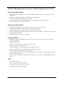
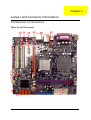
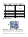
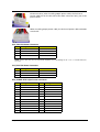
1
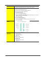
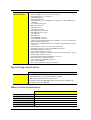
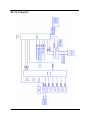
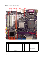
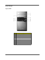
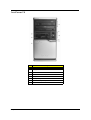
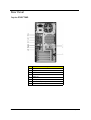
Acer
Aspire E560/T660 and AcerPower F6
Service Guide
Service guide files and updates are
available on the ACER/CSD web. For
more information, please refer to http:/
/csd.acer.com.tw
PRINTED IN TAIWAN
Revision History
Please refer to the table below for the updates of Desktop Aspire E560/T660 and AcerPower F6
service guide.
Date
September 11, 2006
II
Chapter
Updates
first release
Copyright
Copyright© 2006 by Acer Incorporated. All rights reserved. No part of this publication may be
reproduced, transmitted, transcribed, stored in a retrieval system, or translated into any
language or computer language, in any form or by any means, electronic, mechanical, magnetic,
optical, chemical, manual or otherwise, without the prior written permission of Acer
Incorporated.
III
Disclaimer
The information in this guide is subject to change without notice.
Acer Incorporated makes no representations or warranties, either expressed or implied, with
respect to the contents hereof and specifically disclaims any warranties of merchantability or
fitness for any particular purpose. Any Acer Incorporated software described in this manual is
sold or licensed “as is”. Should the programs prove defective following their purchase, the buyer
(and not Acer Incorporated, its distributor, or its dealer) assumes the entire cost of all necessary
servicing, repair, and any incidental or consequential damages resulting from any defect in the
software.
Acer is a registered trademark of Acer Incorporated.
Other brand and product names are trademarks and/or registered trademarks of their respective
holders.
IV
Conventions
The following conventions are used in this manual:
SCREEN MESSAGES
Denotes actual messages that appear on screen.
NOTE
Gives bits and pieces of additional information
related to the current topic.
WARNING
Alerts you to any damage that might result from
doing or not doing specific actions.
CAUTION
Gives precautionary measures to avoid possible
hardware or software problems.
IMPORTANT
Reminds you to do specific actions relevant to the
accomplishment of procedures.
V
Preface
Before using this information and the product it supports, please read the following general
information.
1. This Service Guide provides you with all technical information relating to the BASIC CONFIGURATION
decided for Acer's “global” product offering. To better fit local market requirements and enhance
product competitiveness, your regional office MAY have decided to extend the functionality of a
machine (e.g. add-on card, modem, or extra memory capability). These LOCALIZED FEATURES will NOT
be covered in this generic service guide. In such cases, please contact your regional offices or the
responsible personnel/channel to provide you with further technical details.
2. Please note WHEN ORDERING FRU PARTS, you should check the most up-to-date information available
on your regional web or channel. For whatever reason, if a part number change is made, it will not be
noted in the printed Service Guide. For ACER-AUTHORIZED SERVICE PROVIDERS, your Acer office may
have a DIFFERENT part number code to those given in the FRU list of this printed Service Guide. You
MUST use the list provided by your regional Acer office to order FRU parts for repair and service of
customer machines.
VI
Chapter 1
System Specification
Overview
Main Board
Description
Size
Max. 244 mm x 244 mm, MicroATX
Processor
• Socket type: Intel socket T LGA775 pin
• Socket quantity: one
• Intel Prescott 775 / Smithfield / Cedar Mill / Presler / Conroe, FSB 533/800/
1066MHz (FMB 95W or lower)
• Intel Celeron D 775, FSB 533MHz
System Chipset
• GMCH: ATI RC415s
• ICH: ATI SB600
Memory
• Two DDR2 connectors
• Capacity:
• 256MB to 1GB DDR2 667/533/400 unbuffered ECC SDRAM module
support
• Max. 256MB to 4GB memory support
• Dual-channel function enabled when plugging in two same memory
size DDR2 memory modules
Onboard Graphic
Solution
• ATI RC415s integrated graphics device (IGD) solution
• DVMT technology support
• One VGA port on the rear side
PCI Express / PCI
Slots
• One PCI Express x16 slot
• One PCI Express x1 slot
• Two PCI 2.2 5V slots
FDD
• One slot for FDD
• 1.44MB / 3 mode 3.5” devices support
IDE
• One 40-pin PATA IDE slot, PIO mode 0/1/2/3/4 and ATA mode 33/66/100
support
• Four SATA slots, HDD/CD-ROM/CD-RW/DVD-ROM/DVD-RW/DVD+RW/
DVD Dual/DVD Super Multi Plus support
Audio
• Controller: ATI SB600 compatible
• Chip: HD audio codec ALC888 HD codec 7.1 with S/PDIF out/in
• Connectors support:
• Rear six jacks that follow HD audio definition
• Front microphone in
• Front headphone out
• S/PDIF header (1*3)
• CD-in
• AUX-in
• Front panel audio header (2*5) support
• HD de-pop CKT added
• S/N ration: 90 dB at rear output jack
Chapter 1
1
LAN
• Controller: PCI-E Giga LAN
• H/W, F/W, and S/W should be able to support ASF compliant
USB
•
•
•
•
•
Controller: ATI SB600 compatible
Onboard four USB back panel ports
Connector pin: standard Intel FPIO pin definition
Data transfer rate support: USB 2.0/1.1
For 1394 SKU: ten ports
• Two for front daughter board
• Two for internal USB card reader
• Four for rear I/O (two co-lay with rear I/O, under RJ-45 port, for internal
USB RF & IR receiver board support)
• Two reserved header
• For non-1394 SKU: ten ports
• Four for front daughter board
• Four for rear I/O (two co-lay with rear I/O, under RJ-45 port)
• Two reserved header
Front Panel IO
Header
System LDE
Definition
2
• Power state LED:
• S0: blue steady
• S1/S3: blue blinking
• S4/S5: off
• HDD state LED:
• IDE active: blue blinking
• IDE idle: off
• LAN state LED:
• LAN active: blue blinking
• LAN idle: off
Chapter 1
All Onboard
Connectors List
• Rear I/O connectors:
• One PS/2 keyboard port, one PS/2 mouse port
• One parallel port, one serial port
• One GA (CRT) port
• One RJ-45 LAN port
• Four USB ports for non-1394 SKU; four USB ports + IEEE 1394 port for
1394 SKU
• 7.1 channel phone jack
• Onboard connectors:
• One CPU socket
• Two memory sockets
• One PCI Express x16 socket
• One PCI Express x1 socket
• Two PCI slots
• One FDD slot
• One PATA IDE connector
• Four SATA IDE connectors
• Three 2*7 pin Intel FPIO specification USB pin connectors (follow Intel
FPIO standard specification)
• One 2*5 pin Intel FPIO specification microphone-in/headphone-out pin
connector
• One serial port 2*5 pin connector (2nd serial port)
• One CD-in four-pin connector (CD-ROM audio input)
• One S/PDIF three-pin connector
• One four-pin CPU fan connector
• One four-pin system fan connector with three-pin system fan co-layout
• One intrusion alarm connector
• One 24-pin ATX interface PS3/PS2 SPS connector
• One 2*7 pin front panel IO header
• Two reserved two-pin GPIO connector
• One onboard buzzer
• Color management for onboard connector
Special Design Specification
Description
Thermal Design
• At least four steps fan speed control by hardware monitor
• Intel MTM technology, default read/write enabled
• CPU overheat (120oC) power off protection
• Compliant with Intel 2005 Mainstream and Performance FMB design
• Compliant with Intel 2006 TDP
Wake-Up Event Specification
S1
S3
S4
S5
Power Button
Enabled
Enabled
Enabled
Enabled
PS2 Keyboard
Enabled
Enabled
n/a
n/a
USB Keyboard
Enabled
Enabled
n/a
n/a
WOL (wake on LAN)
n/a
n/a
n/a
n/a
WOR (wake on Ring)
n/a
n/a
n/a
n/a
RTC (real time clock)
n/a
n/a
n/a
Enabled
Chapter 1
3
Block Diagram
4
Chapter 1
Main Board Placement
#
Label
Component
#
Label
Component
1
CPU socket
LGA775 socket for Intel
Pentium D/Pentium 4/
Celeron D CPUs
2
CPU_FAN
CPU cooling fan
connector
3
DIMM1~2
240-pin DDR2 SDRAM
slots
4
IR1
Infrared header
5
CHS1
Chassis detect header
6
ATX_POWER
Standard 24-pin ATX
power connector
7
FDD
Floppy diskette drive
connector
8
IDE1
Primary IDE channel
Chapter 1
5
6
9
CLR_CMOS
Clear CMOS jumper
10
PANEL1
Front panel switch/LED
header
11
SATA1~4
Serial ATA connectors
12
JP2
To be defined
13
JP1
To be defined
14
BIOS_WP
BIOS protect jumper
15
USB3~5
Front panel USB headers
16
1394A1*
Onboard 1394a header
17
COM2
Onboard serial port
header
18
AUDIO1
Front panel audio header
19
SPDIFO2
SPDIF out header
20
PCI1~2
32-bit add-on card slots
21
AUX_IN
Auxiliary In connector
22
PCIEX1
PCI Express x1 slot
23
PCIEX16
PCI Express x16 slot
24
SYS_FAN
System fan connector
25
ATX_12V
Auxiliary 4-pin power
connector
Chapter 1
Front Panel
Aspire E560
#
Chapter 1
Description
1
Optical driver
2
Optical drive eject button
3
Power button
4
USB ports
5
Speaker/Headphone jack
6
Microphone jack
7
Indicators
8
Floppy disk drive
9
Card reader
10
IEEE 1394 port
7
Aspire T660
#
8
Description
1
Optical device
2
Floppy drive
3
Power button
4
Microphone jack
5
Speaker/Headphone jack
6
USB ports
Chapter 1
AcerPower F6
#
Chapter 1
Description
1
Optical driver
2
Floppy disk drive
3
Card reader
4
indicators
5
USB ports
6
Microphone jack
7
Speaker/Headphone jack
8
Power button
9
Rear Panel
Aspire E560/T660
#
10
Description
1
Optical driver
2
Floppy disk drive
3
Card reader
4
indicators
5
USB ports
6
Microphone jack
7
Speaker/Headphone jack
8
Power button
Chapter 1
Acer Empowering Technology
Acer’s innovative Empowering Technology makes it easy for you to access frequently used
functions and manage your new Acer notebook. It features the following handy utilities:
AcerPower F6
•
Acer eSettings Management accesses system information and adjusts settings easily.
•
Acer eLock Management limits access to external storage media.
•
Acer eDataSecurity Management protects data with passwords and advanced encryption
algorithms.
•
Acer ePerformance Management improves system performance by optimizing disk space, memory
and registry settings.
•
Acer eAcoustics Management offers a useful tool to balance your computing power needs with
your desired level of quietness.
•
Acer eRecovery Management backs up and recovers data flexibly, reliably and completely.
Aspire E560/T660
•
Acer eDataSecurity Management protects data with passwords and advanced encryption
algorithms.
•
Acer ePerformance Management improves system performance by optimizing disk space, memory
and registry settings.
•
Acer eRecovery Management backs up and recovers data flexibly, reliably and completely.
For more information, press the
key to launch the Empowering Technology menu, then click
on the appropriate utility and select the Help or Tutorial function.
Empowering Technology password
Before using Acer eLock Management and Acer eRecovery Management, you must initialize the
Empowering Technology password. Right-click on the Empowering Technology toolbar and
select “Password Setup” to do so. If you do not initialize the Empowering Technology password,
you will be prompted to do so when running Acer eLock Management or Acer eRecovery
Management for the first time.
Chapter 1
11
Acer eSettings Management
Acer eSettings Management allows you to inspect hardware specifications, change BIOS
passwords or other Windows settings, and to monitor the system health status. Acer eSettings
Management also:
•
Provides a simple graphical user interface for navigating.
•
Displays general system status and advanced monitoring for power users on Acer computer.
Acer eLock Management
Acer eLock Management is a security utility that allows you to lock your removable data, optical
and floppy drives to ensure that data can’t be stolen while your notebook is unattended.
•
Removable data devices - includes USB disk drives, USB pen drives, USB flash drives, USB MP3 drives,
USB memory card readers, IEEE 1394 disk drives and any other removable disk drives that can be
mounted as a file system when plugged into the system.
•
Optical drive devices - includes any kind of CD-ROM or DVD-ROM drives.
•
Floppy disk drives - 3.5-inch disks only.
•
Interfaces - includes serial ports, parallel port, infrared (IR), and Bluetooth.
To activate Acer eLock Management, a password must be set at first. Once set, you can apply
locks to any of the devices. Lock(s) will immediately be set without any reboot necessary, and will
remain locked after rebooting, until unlocked.
Note: If you lose your password, there is no method to reset it except by reformatting your notebook
12
Chapter 1
or taking your notebook to an Acer Customer Service Center. Be sure to remember or write down your
password.
Acer eDataSecurity Management
Acer eDataSecurity Management is handy file encryption utility that protects your files from
being accessed by unauthorized persons. It is conveniently integrated with Windows explorer as
a shell extension for quick and easy data encryption/decryption and also supports on-the-fly file
encryption for MSN Messenger and Microsoft Outlook.
The Acer eDataSecurity Management setup wizard will prompt you for a supervisor password
and default encryption. This encryption will be used to encrypt files by default, or you can choose
to enter your won file-specific password when encrypting a file.
Note: The password used encrypt a file is the unique key that the system needs to decrypt it. If you lose
the password, the supervisor password is the only other key capable of decrypting the file. If you lose
both passwords, there will be no way to decrypt your encrypted file! Be sure to safeguard all
related passwords!
Chapter 1
13
14
Chapter 1
Acer ePerformance Management
Acer ePerformance Management is a system optimization tool that boosts the performance of
your Acer notebook. It provides and express optimization method to release unused memory and
disk space quickly. The user can also enable advanced options for full control over the following
option:
•
Memory optimization - releases unused memory and check usage.
•
Disk optimization - removes unneeded items and files.
•
Speed optimization - improves the usability and performance of your Windows XP system.
Acer eAcoustics Management
Acer eAcoustics Management offers you a useful tool to balance your computing power needs
with your desired level of quietness. By reducing the processor speed for tasks that require less
processing, the CPU and system fans can run slower, thus reducing the amount of sound
generated by these components.
Using Acer eAcoustics Management
To launch Acer eAcoustics Management
•
Click on the Acer eAcoustics Management icon in the Empowering Technology toolbar.
•
From the Start menu, go to (All) Programs > Acer Empowering Technology > Acer eAcoustics
Management.
Chapter 1
15
Then Acer eAcoustics Management main page will come out.
Acer eAcoustics Management Main Page
Listed on the main page are two options for Acer eAcoustics Management, labeled as Quiet and
Professional. Select the mode that suits your working requirements best, and exit the utility to
apply the settings.
Quiet
Use this mode for tasks that require low processing power, like word processing, Web browsing,
and instant messaging. This mode creates the lowest audio disturbance.
Professional Mode
Use this mode for processing-intensive tasks, when you require full-speed operation.
16
Chapter 1
Acer eRecovery Management
Acer eRecovery Management is a powerful utility that does away with the need for recovery
disks provided by the manufacturer. The Acer eRecovery Management utility occupies space in a
hidden partition on your system’s HDD. User-created backups are stored on D:\ drive. Acer
eRecovery Management provides you with:
•
Password protection
•
Recovery of applications and drivers
•
Image/data backup
•
•
Backup to HDD (set recovery point)
•
Backup to CD/DVD
Image/data recovery tools
•
Recovery from a hidden partition (factory defaults)
•
Recovery from the HDD (most recent user-defined recovery point)
•
Recover from CD/DVD
For more information, please refer to Acer eRecovery Management.
Note: If your computer did not come with a Recovery CD or System CD, please use Acer eRecovery
Management’s System backup to optical disk feature to burn a backup image to CD or DVD. To
ensure the best results when recovering your system using a CD or Acer eRecovery Management,
detach all peripherals (except the external Acer ODD, if your computer has one), including the ezDock.
Chapter 1
17
Acer Disc-to-Disc Recovery
Restore without a Recovery CD
This recovery process helps you restore the C:\ drive with the original software content that is
installed when you purchase your system. Follow the steps below to rebuild your C:\ drive.
Note: The C:\ drive will be reformatted and all data will be erased. It is important to back up all data
files before you use this option.
1. Restart the system.
2. While the Acer logo comes out, press <Alt> + <F10> to enter the recovery process.
3. The message The system has password protection. Please enter 000000: will be displayed.
4. Enter six zeros and continue.
5. The Acer Recovery main page appears.
6. Use the arrow keys to scroll through the items (operating system versions) and press <Enter> to select.
Multilingual Operating System Installation
Follow the instructions to choose the operating system and language you prefer when you first
power on the system.
1. Turn on the system.
2. Acer’s multilingual operating system selection menu will pop up automatically.
3. Use the arrow keys to scroll to the language version you want. Press <Enter> to confirm your selection.
4. The operating system and language you choose now will be the only option for future recovery
operations.
5. The system will install the operating system and language you choose.
18
Chapter 1
Chapter 1
19
20
Chapter 1
Hardware Specification and Configuration
Processor
Item
Specification
Type
Intel Prescott 775 / Smithfield / Cedar Mill / Presler / Conroe
Feature
• FSB: 533/800/1066MHz
• Socket type: Intel socket T LGA 775-pin
• HyperThreading Technology and FSB Dynamic Bus Inversion (DBI)
support
• 36-bit host bus addressing support, allowing the CPU to access the entire
GMCH memory address space
System Main Chipset
Item
Specification
Core logic
ATI RC415 + ATI SB600
System clock
ICS ICS6304471
BIOS ROM
SST 49LF040B
Memory controller
ATI RC415
Super I/O controller
ITE IT8718F-S
Audio Codec & Amplifier
Realtek ALC888 (high definition audio)
North Bridge
Item
Specification
Chipset
ATI RC415
Feature
• 64-bit DDR2 SDRAM system memory interface for optimal performance
support
• One x2 (expandable to x4) A-Link Express interface (PCI Express 1.0a
compliant) for connection to the ATI IXP
• One PCI Express x16 graphics interface support, fully compliant to the PCI
Express Base Specification revision 1.0a
• DDR2 667/533/400 SDRAM support
South Bridge
Item
Specification
Chipset
ATI SB600
Feature
•
•
•
•
•
•
Chapter 1
Enhanced DMA controller, interrupt controller, and timer functions
Compliant to PCI Express Base Specification v1.0a
Compliant to PCI 2.3 specification at 33MHz
Compliant to SATA2 specification
Integrated USB 2.0 Host Controller support up to ten USB 2.0 ports
Compliant to AC’97 Codec/High Definition Audio Codec support eightchannel audio output
• Integrated IDE controller support Ultra DMA 133/100/66
21
System Memory
Item
Feature
Specification
• DDR2 667/533/400MHz SDRAM memory interface design with singlechannel DDR2 architecture
• Accommodates two unbuffered DIMMS slots
• Maximum memory up to 2GB
Onboard LAN
Item
Feature
Specification
•
•
•
•
•
•
Two-wire serial interface (TWSI) for VPD
Compliant to PCI Express base specification 1.1
Compliant to 802.3x flow control
IEEE 802.3u/ab, 802.1p and 802.1q support
Compliant to 10/100/1000 IEEE 802.3
WOL power management and ACPI 2.0 specification
1394 Fireware
Item
Feature
Description
• Fully compliant to provisions of IEEE Std 1394-1395 or a high
performance serial bus and IEEE Std 1394a-2000
• Three IEEE Std 1394a-2000 fully compliant cable ports at 100/200/400 Mb/
s
Audio
Item
Feature
Description
• High performance DACs with 97dB SNR (A-weighting), ADCs with 90dB
SNR (A-weighting)
• 3.3V digital core power; 1.5V~3.3V digital IO power for HDA bus;
3.3V~5.0V analog power
• High quality analog differential CD input
• Meets performance requirements for Microsoft WLP 3.0 audio Premium
desktop and mobile PCs
BIOS Hotkey List
Hotkey
DEL
22
Description
To enter BIOS Setup Utility: press the DEL key while the system is booting
to enter BIOS Setup Utility.
Chapter 1
Hardware Monitor Function
Item
Feature
Description
• Smart fan control system, Thermal Cruise and Speed Cruise support
• Six VID input pins for CPU Vcore identification
• Two thermal inputs from optionally remote thermistors or 2N3904
transistors or Pentium 4 thermal diode output
• Four external voltage detect inputs
• Three intrinsic voltage monitoring (typical for Vbat, +5VSB, +5CC)
• Two fan speed monitoring inputs
• Two fan speed control (DC analog output)
• WATCHDOG comparison of all monitored items
• Overheat indication output
• Issue SMI#, IRQ, OVT# to activate system protection
Environment Requirements
Item
Specification
Temperature
Operating
+5OC ~ +35OC
Non-operating
-20OC ~ +60OC (storage packed), -10OC ~ +60OC (unpacked)
Humidity
Operating
15% to 80% RH, non-condensing
Non-operating
10% to 90% RH, non-condensing at 40oC
Vibration
Operating
5 ~ 500Hz, 2.20g RMS random, 10 minutes per axis in all three axes
Non-operating
5 ~ 500Hz, 1.09g RMS random, one hour per axis in all three axes
Drop Test
Drop Test
Definition
The protection ability of packing & cushion must be capable of
withstanding, with no physical or functional damage, mechanical impact
from height-specific drops.
Test Standard
Package Cross Weight
Drop Height
Not of Drop
KGs
lbs
CM
Inch
0~9.1
0~20
76
30
9.1~18.2
20~40
61
24
10
18.2~27.3
40~60
46
18
10
27.3~45.4
60~100
31
12
10
10
10 drops: one corner, three edges, six surfaces
Chapter 1
23
Power Management Function (ACPI Support Function)
Device Standby Mode
•
Independent power management timer for hard disk drive devices (zero to 15 minutes, time step =
one minute).
•
Hard disk drive goes into Standby mode (for ATA standard interface).
•
Disable V-sync to control the VESA DPMS monitor.
•
Resume method: device activated (keyboard for DOS, keyboard & mouse for Windows).
•
Resume recovery time: three to five seconds.
Global Standby Mode
•
Global power management timer (two to 120 minutes, time step = 10 minutes).
•
Hard disk drive goes into Standby mode (for ATA standard interface).
•
Disable H-sync and V-sync signals to control the VESA DPMS monitor.
•
Resume method: return to original state by pushing external switch button, modem ring in, keyboard
and mouse for APM mode.
•
Resume recovery time: seven to 10 seconds.
Suspend Mode
•
Independent power management timer (two to 120 minutes, time step = 10 minutes) or pushing
external switch button.
•
CPU goes into SMM.
•
CPU asserts STPCLK# and goes into the Stop Grant state.
•
LED on the panel turns amber color.
•
Hard disk drive goes into SLEEP mode (for ATA standard interface).
•
Disable H-sync and V-sync signals to control the VESA DPMS monitor.
•
Ultra I/O and VGA chip go into power saving mode.
•
Resume method: return to original state by pushing external switch button, modem ring in, keyboard
and mouse for APM mode.
•
Return to original state by pushing external switch button, modem ring in and USB keyboard for ACPI
mode.
ACPI
•
ACPI specification 1.0b
•
S0, S1, S3 and S5 sleep state support
•
Onboard device power management support
•
Onboard device configuration support
24
Chapter 1
Chapter 2
Setup Utilities
About the Setup Utility
The computer uses the latest Award BIOS (Basic Input and Output System) with support for
Windows Plug and Play. The CMOS chip on the main board contains the ROM setup instructions
for configuring the main board BIOS.
The BIOS Setup Utility displays the system’s configuration status and provides you with options to
set system parameters. The parameters are stored in Battery-backed-up CMOS RAM that saves
this information when the power is turned off. When the system is turned back on, the system is
configured with the values you have stored in CMOS.
The BIOS Setup Utility enables you to configure:
•
Hard drives, diskette drives and peripherals
•
Video display type and display options
•
Password protection from unauthorized use
•
Power management features
The settings made in the Setup Utility affect how the computer performs. Before using the Setup
Utility, ensure that you understand the Setup Utility options.
Chapter 2
23
Entering the Setup Utility
When you power on the system, BIOS enters the Power-On Self Test (POST) routines. POST is a
series of built-in diagnostics performed by the BIOS. After the POST routines are completed, the
following message will appear.
Press DEL to enter SETUP
Press the delete key to enter the BIOS Setup Utility.
CMOS Setup Utility -- Copyright (C) 1985-2005, American Megatrends, Inc.
fProduct Information
fStandard CMOS Features
fAdvanced BIOS Features
fAdvanced Chipset Features
fIntegrated Peripherals
fPower Management Setup
fPnP/PCI Configurations
Enter : Select
: Move
F1:General Help
f PC Health Status
f Frequency Control
f
f
Load Optimized Defaults
Set Supervisor Password
Set User Password
Save & Exit Setup
Exit Without Saving
+/-/: Value F10: Save & Exit
F9: Optimized Defaults
ESC: Exit
BIOS Navigation Keys
The BIOS navigation keys are listed below.
Key
24
Function
ESC
Exits the current menu.
IKLJ
Scrolls through the items on a menu.
+/-/PU/PD
Modifies the selected field’s values.
F1
Displays a screen that describes all key functions.
F9
Loads an optimized setting for better performance.
F10
Saves the current configuration and exits setup.
Chapter 2
Product Information
This option displays basic information about the system. Press <Esc> to return to the main menu
setting page.
Phoenix-AwardBIOS CMOS Setup Utility
Product Information
Product Name
System S/N
Main Board ID
Main Board S/N
System BIOS Version
SMBIOS Version
BIOS Release Date
: Move
Chapter 2
ASE380/AST180/APM8
Item Help
EC51GM
R01-A0
R01-A0
2.3.3
07/22/06
Enter : Select +/-/: Value F10: Save & Exit
F1:General Help
F9: Optimized Defaults
ESC: Exit
25
Standard CMOS Features
The option displays basic information about the system. Press <Esc> to return to the main menu
setting page.
CMOS Setup Utility - Copyright (C) 1985-2005, American Megatrends, Inc.
Standard CMOS Setup
Date
Time
Thu 07/13/2006
00: 01: 44
f IDE Primary Master
f IDE Primary Slave
f S-ATA 1
2
f S-ATA
3
f S-ATA
S-ATA
4
f
Drive A
Halt On
Base Memory
Extended Memory
Total Memory
: Move
Not Detected
ATAPI CDROM
Not Detected
Not Detected
Not Detected
Not Detected
Help Item
Use [ENTER], [TAB]
or [SHIFT-TAB] TO
select a field.
Use [+] or [-] to
configure system Time.
1.4 MB 31/2’’
All. But Keyboard
640K
383M
512M
Enter : Select +/-/: Value F10: Save & Exit
F1:General Help
F9: Optimized Defaults
ESC: Exit
Date and Time
The Date and Time items show the current date and time set on the computer. If you are running
a Windows OS, these items are automatically updated whenever you make changes to the
Windows Date and Time Properties utility.
IDE Primary Master/Slave SATA 1~4
Your computer has one IDE channel and can be installed with one or two devices (Master and
Slave). Use this item to configure each device on the IDE channel. This main board features four
SATA connectors supporting four SATA drives. SATA refers to Serial ATA (Advanced Technology
Attachment), the standard interface for the IDE hard drives which are currently used in most PCs.
Drive A
The item defines the properties of any diskette drive attached to the system.
Halt On
This item defines the operation of the system POST (Power On Self Test) routine. YOu can use this
item to select which types of errors in the POST are sufficient to halt the system.
26
Chapter 2
Advanced BIOS Features
This page sets up more advanced information about the system. Handle this page with caution.
Any changes can affect the operation of the system.
CMOS Setup Utility - Copyright (C) 1985-2005, American Megatrends, Inc.
Advanced BIOS Features
f
f
f
: Move
f
Disabled
Enabled
Enabled
Disabled
1st FLOPPY DRIVE
JetFlash TS1GJF2A/1
PIONEER DVD-ROM DVD
Press Enter
Press Enter
Press Enter
Enabled
On
Fast
Enabled
Disabled
Disabled
12
Disabled
12
12
Enabled
Enabled
Help Item
Enable/Disable
Boot Sector Virus
Protection.
f
Virus Warning
Quick Power on Self Test
Silent Boot
Configuration Table
First Boot Device
Second Boot Device
Third Boot Device
Hard Disk Drives
Removable Drives
CD/DVD Drives
Boot Other Device
Boot Up Numlock Status
Gate A20 Option
APIC Mode
HDD SMART Capability
BIOS Write Protect
BootBlock BIOS Write Protect
Auto Detect DIMM/PCI Clk
Spread Spectrum
Enter : Select +/-/: Value F10: Save & Exit
F1:General Help
F9: Optimized Defaults
ESC: Exit
Virus Warning
This item enables or disables the boot sector virus protection.
Quick Power On Self Test
You can enable this item to shorten the power on self testing (POST) and have your system
startup faster. You might like to enable this item after you are confident that your system
hardware is operating smoothly.
Silent Boot
If enabled, BIOS will show a full screen logo at boot. If disabled, BIOS will set the initial display
mode to BIOS and show the diagnostic POST screen at boot.
Configuration Table
Use this item to show summary screen.
First / Second / Third Boot Device
Use this item to determine the device order of the devices that your system searches for an
operating system to load at start-up time. The devices showed here will be different depending
on the exact devices installed on the main board.
Chapter 2
27
Hard Disk Drives
Scroll this item and press <Enter> to view the following screen.
CMOS Setup Utility - Copyright (C) 1985-2005, American Megatrends, Inc.
Hard Disk Drives
Item Help
Hard Disk Drives
1st Drive
JetFlash TS1GJF2A/1
: Move
Specifies the boot
sequence from the
available devices.
F10: Save & Exit
Enter : Select +/-/: Value
F1:General Help
F9: Optimized Defaults
ESC: Exit
Removable Drives
Scroll this item and press <Enter> to view the following screen.
CMOS Setup Utility - Copyright (C) 1985-2005, American Megatrends, Inc.
Removable Drives
Item Help
Removable Drives
1st Drive
1st FLOPPY DRIVE
: Move
28
Specifies the boot
sequence from the
available devices.
Enter : Select +/-/: Value F10: Save & Exit
F1:General Help
F9: Optimized Defaults
ESC: Exit
Chapter 2
CD/DVD Drives
Scroll this item and press <Enter> to view the following screen. Press <Esc> to return to the main
menu setting page.
CMOS Setup Utility - Copyright (C) 1985-2005, American Megatrends, Inc.
Removable Drives
Item Help
Removable Drives
1st Drive
PIONEER DVD-ROM DVE
: Move
Specifies the boot
sequence from the
available devices.
F10: Save & Exit
Enter : Select +/-/: Value
F1:General Help
F9: Optimized Defaults
ESC: Exit
Boot Other Device
When enabled, the system searches all other possible locations for an operating system if it fails
to find one in the devices specified under the First, Second, and Third boot devices.
Boot Up NumLock Status
This item defines if the keyboard NumLock key is active when your system is booted.
Gate A20 Option
This item defines how the system handles legacy software that was written for an earlier
generation of processors. Set this item for the default value.
APIC Mode
This item allows you to enable or disable the APIC (Advanced Programmable Interrupt Controller)
mode. APIC provides symmetric multi-processing (SMP) for systems, allowing support for up to 60
processors.
HDD S.M.A.R.T Capability
The S.M.A.R.T (Self-Monitoring, Analysis, and Reporting Technology) system is a diagnostics
technology that monitors and predicts device performance. S.M.A.R.T software resides on both
the disk drive and the host computer.
BIOS Write Protect (Disabled)
This item disables BIOS write protect function.
Chapter 2
29
Boot Block BIOS Write Protect (Disabled)
This item disables Boot Block BIOS write protect function.
Auto Detect DIMM/PCI Clk (Enabled)
This item determines whether the BIOS should actively reduce EMI (Electromagnetic Interference)
and reduce power consumption by turning off unoccupied or inactive expansion slots.
Spread Spectrum (Disabled)
If you enable this item, it can significantly reduce the EMI (Electromagnetic Interference)
generated by the system.
Hyper-Threading Technology (Enabled)
This item enables or disables Hyper-Threading technology function.
Surround View Function (Disabled)
This item enables or disables surround view function.
30
Chapter 2
Advanced Chipset Features
This page sets up more advanced information about the system. Handle this page with caution.
Any changes can affect the operation of the system.
CMOS Setup Utility - Copyright (C) 1985-2005, American Megatrends, Inc.
Advanced Chipset Setup
Boot Graphics Adapter Priori
Current UMA Size:
PEG/IGD
128 MB
Help Item
Select which graphics
controller to use as
the primary boot
device.
: Move
Enter : Select +/-/: Value F10: Save & Exit
F1:General Help
F9: Optimized Defaults
ESC: Exit
Boot Graphics Adapter (PEG/IGD)
This item allows you to choose the primary graphics adapter.
Current UMA Size (256MB)
This item shows the current UMA size.
Chapter 2
31
Integrated Peripherals
This page sets up some parameters for peripheral devices connected to the system. Press <Esc> to
return to the main menu setting page.
CMOS Setup Utility - Copyright (C) 1985-2005, American Megatrends, Inc.
Integrated Peripherals
OnBoard PCI S-ATA Controller
USB 2.0 Support
USB Controller
Onboard LAN Controller
Onboard LAN Boot ROM
Onboard IEEE1394 Controller
Serial Port1 Address
Serial Port2 Address
Serial Port2 Mode
Parallel Port Address
Parallel Port Mode
ECP Mode DMA Channel
Parallel Port IRQ
: Move
IDE
Enabled
Enabled
Enabled
Disabled
Enabled
3F8/IRQ4
2F8/IRQ3
Normal
378
ECP
DMA3
IRQ7
Help Item
Option
IDE
Enter : Select +/-/: Value F10: Save & Exit
F1:General Help
F9: Optimized Defaults
ESC: Exit
Onboard PCI SATA Controller (RAID)
Use this item to enable or disable the onboard PCI SATA controller.
USB 2.0 Support (Enabled)
Use this item to enable or disable the USB 2.0 support.
USB Controller (Enabled)
Use this item to enable or disable the USB controller.
Onboard LAN function (Enabled)
User this item to enable or disable the onboard LAN function.
Onboard LAN Boot ROM (Disabled)
Use this item to enable or disable the booting from the onboard LAN or a network add-on card
with a remote boot ROM installed.
Onboard IEEE 1394 Controller (Enabled)
Use this item to enable or disable the onboard VIA 1394 device.
32
Chapter 2
Serial Port 1/2 Address (3F8/IRQ4/2F8/IRQ3)
This item allows users to manually set the address for serial port 1 and port 2.
Serial Port 2 Mode (Normal)
Use this item to enable or disable the onboard serial port and to assign a port address.
Parallel Port Address (378)
Use this item to enable or disable the onboard parallel port and to assign a port address.
Parallel Port Mode (ECP)
Use this item to set the parallel port mode. You can select Normal (Standard Parallel Port), ECP
(Extended Capabilities Port), EPP (Enhanced Parallel Port), or EPP & ECP.
ECP Mode DMA Channel (DMA3)
When the onboard parallel port is set to ECP mode, the parallel port can use DMA3 or DMA1.
Parallel Port IRQ (IRQ7)
Use this item to assign IRQ to the parallel port.
Chapter 2
33
Power Management Setup
This page sets up some parameters for system power management operation. Press <Esc> to
return to the main menu setting page.
CMOS Setup Utility - Copyright (C) 1985-2005, American Megatrends, Inc.
Power Management Setup
ACPI function
ACPI Suspend Type
Soft-off by PWR-BTTN
Power On After Power Fail
Resume On LAN
Wake-Up by PME
Power On by Ring
USB KB Wake Up from S3
PS2 Keyboard Wakeup
PS2 Mouse Wakeup
Resume by Alarm
: Move
Enabled
S3 (STR)
Delay 4 Sec
Last State
Disabled
Enabled
Disabled
Disabled
Disabled
Disabled
Disabled
Help Item
Enable/Disable
ACPI support for
Operating System.
ENABLE: If OS
supports ACPI.
DISABLED: If OS
does not support
ACPI.
Enter : Select +/-/: Value F10: Save & Exit
F1:General Help
F9: Optimized Defaults
ESC: Exit
ACPI Function (Enabled)
This item allows users to enable or disable the ACPI power management function.
ACPI Suspend Type (S3(STR))
You can use this item to define how your system suspends. In the default, S3 (STR), the suspend
mode is a suspend to RAM, i.e., the system shuts down with the exception of a refresh current to
the system memory.
Soft-Off by PWR-BTTN (Delay 4 Sec.)
Under ACPI (Advanced Configuration and Power management Interface) you can create a
software power down. In a software power down, the system can be resumed by Wake Up
Alarms. This item lets you install a software power down that is controlled by the power button
on the system. If the item is set to Delay 4 Sec., then you have to hold the power button down for
four seconds to cause a software power down.
Power On After Power Fail (Last State)
This item enables the system to restart automatically or return to its operating status.
Resume on LAN (Disabled)
The system can be turned off with a software command. If you enable this item, the system can
automatically resume on LAN. You must use an ATX power supply in order to user this feature.
34
Chapter 2
Wake-Up by PME (Enabled)
The system can be turned off with a software command. If you enable this item, the system can
automatically resume if there is an incoming call on the PCI modem or PCI LAN card. You must
use an ATX power supply in order to use this feature. Use this item to do wake-up action if
inserting the PCI card.
Power On by Ring (Disabled)
The system can be turned off with a software command. If you enable this item, the system can
automatically resume if there is an incoming call on the modem. You must use the ATX power
supply in order to use this feature.
USB KB Wake Up from S3 (Enabled)
This item allows you to enable/disable the USB device wake-up function from S3/S4 mode.
PS2 Keyboard Wake-up (Disabled)
This item allows you to enable or disable the keyboard activity to awaken the system from power
saving mode.
PS2 Mouse Wake-up (Disabled)
This item can enable or disable the mouse movement to awaken the system from power saving
mode.
Resume by Alarm (Disabled)
Under ACPI (Advanced Configuration and Power Management Interface) you can create a
software power down. In a software power down, the system can be resumed by Wake Up
Alarms. This item lets you install a software power down that is controlled by the power button
on your system. If the item is set for Instant-Off, then the power button causes a software power
down. If the item is set for Delay four Sec., then you have to hold the power button down for
four seconds to cause a software power down.
Chapter 2
35
PCI/PnP Configuration
This page sets up some parameters for devices installed on the PCI bus and those utilizing the
system plug and play capability.
CMOS Setup Utility - Copyright (C) 1985-2005, American Megatrends, Inc.
PCI / PnP Configuration
Allocate IRQ to PCI VGA
IDE BusMaster
: Move
Yes
Enabled
Help Item
YES: Assigns IRQ to
PCI VGA card if card
requests IRQ.
NO: Does not assign
IRQ to PCI VGA card
even if card requests
an IRQ.
Enter : Select +/-/: Value F10: Save & Exit
F1:General Help
F9: Optimized Defaults
ESC: Exit
Allocate IRQ to PCI VGA (Yes)
If this item is enabled, an IRQ will be assigned to the PCI VGA graphics system. You set this value
to No to free up an IRQ.
IDE Bus Master (Enabled)
This item is used to enable or disable IDE Bus Master.
36
Chapter 2
PC Health Status
This item lets you monitor the parameters for critical voltages, temperature and fan speeds. Press
<Esc> to return to the main menu setting page.
CMOS Setup Utility - Copyright (C) 1985-2005, American Megatrends, Inc.
PC Health Status
Hardware Health Event Monitoring
VCore
+3.3V
+5V
+12V
VDIMM
5VSB
Current CPU fan speed
Current System fan speed
Current CPU temperature
Current System temperature
ShutDown Temperature
CPU Smart Fan Function
System Smart Fan Function
: Move
Help Item
: 1.312 V
: 3.376 V
: 5.120 V
: 11.968 V
: 1.792 V
: 5.278 V
: 2500 RPM
: 0 RPM
: 66°C/150°F
: 37°C/98°F
90°C/194°F
Enabled
Disabled
Option
Disabled
70°C/158°F
80°C/176°F
90°C/194°F
Enter : Select +/-/: Value F10: Save & Exit
F1:General Help
F9: Optimized Defaults
ESC: Exit
System Component Characteristics
This items display the monitoring of the overall hardware health status.
•
VCore
•
+3.3V
•
+5V
•
+12V
•
VDIMM
•
5VSB
•
Current CPU fan speed
•
Current system fan speed
•
Current CPU temperature
•
Current system temperature
Shut Down Temperature
Enables you to set the maximum temperature that the system can reach before powering down.
Chapter 2
37
CPU Smart Fan Function (Enabled)
This item is used to enable or disable CPU smart fan function.
System Smart Fan Function (Disabled)
This item is used to enable or disable CPU smart fan function.
38
Chapter 2
Frequency Control
You can set the clock speed and system bus for the computer. The clock speed and system bus are
determined by the kind of processor you have installed on the main board. Press <Esc> to return
to the main menu setting page.
CMOS Setup Utility - Copyright (C) 1985-2005, American Megatrends, Inc.
Frequency/Voltage Control
Configure advanced CPU settings
Module Version: 3D.03
Help item
Manufacturer : Intel
Brand String : Genuine Intel (R) CPU 3.80GHz
Frequency
: 3.80GHz
FSB Speed : 800MHz
Cache L1
: 16 KB
Cache L2
: 1024 KB
Ratio Status : Unlocked (Max: 19, Min: 14)
Ratio Actual Value: 14
Current CPU Clock : 3.80GHz
: Move
Enter : Select +/-/: Value F10: Save & Exit
F1:General Help
F9: Optimized Defaults
ESC: Exit
Manufacturer/Brand String/Frequency/FSB Speed
There are display-only fields and show the information of current manufacturer, brand of COU,
frequency and Front side Bus of the CPU installed on the main board.
Cache L1/L2
These items show the actual CPU internal level 1/2 cache size.
Ratio Status/Ratio Actual Value
These items show the locked ratio status and the actual ratio of the CPU installed on the main
board.
Current CPU Clock (3.80GHz)
Use this item to set current CPU clock.
Chapter 2
39
Set Supervisor Password
This page helps you install or change a password. Press <Esc> to return to the main menu setting
page.
CMOS Setup Utility - Copyright (C) 1985-2005, American Megatrends, Inc.
Supervisor Password
Help item
Supervisor Password : Not Installed
Change Supervisor Password
: Move
Press Enter
Install or Change the
password.
Enter : Select +/-/: Value F10: Save & Exit
F1:General Help
F9: Optimized Defaults
ESC: Exit
Supervisor Password (Not Installed)
This item indicates whether a supervisor password has been set. If the password has been
installed, installed will display. If not, Not Installed will come out.
Change Supervisor Password (Press Enter)
You can select this option and press <Enter> to access the sub menu. You can use the submenu to
change the supervisor password.
40
Chapter 2
Set User Password
This item helps you set or change a password. Press <Esc> to return to the main menu setting
page.
CMOS Setup Utility - Copyright (C) 1985-2005, American Megatrends, Inc.
User Password
Help item
User Password : Not Installed
Change User Password
: Move
Press Enter
Install or Change the
password.
Enter : Select +/-/: Value F10: Save & Exit
F1:General Help
F9: Optimized Defaults
ESC: Exit
User Password (Not Installed)
This item indicates whether a supervisor password has been set. If the password has been
installed, installed will display. If not, Not Installed will come out.
Change User Password (Press Enter)
You can select this option and press <Enter> to access the sub menu. You can use the submenu to
change the user password.
Load Optimized Defaults
This option will open a dialog box that lets you install stability-oriented defaults for all
appropriate items in the Setup Utility. Select [OK] then press <Enter> to install the defaults. Select
[Cancel] then press <Enter> to not install the defaults.
Save and Exit Setup
You can highlight this item and press <Enter> to save the changes that you have made in the
Setup Utility and exit the Setup Utility. When the Save and Exit dialog box appears, press [OK] to
save and exit, or press [Cancel] to return to the main menu.
Chapter 2
41
Exit without Saving
You can highlight this item and press <Enter> to discard any changes that you have made in the
Setup Utility and exit the Setup Utility. When the Exit without Saving dialog box appears, press
[OK] to discard changes and exit, or press [Cancel] to return to the main menu.
NOTE: If you have made settings that you do not want to save, choose Discard Changes and Exit
and press [OK] to discard any changes you have made.
42
Chapter 2
Chapter 3
Machine Disassembly and Replacement
General Information
This chapter contains step-by-step procedures on how to disassemble the Aspire E560/T660 and
AcerPower F6 for maintenance and troubleshooting.
To disassemble the notebook, you need the tools below:
•
Wrist ground strap and conductive mat for preventing electrostatic discharge
•
Small Philips screw driver
•
Flat head screw driver
•
Hexagonal driver
•
Tweezers
NOTE: The screws for the different components vary in size. During the disassembly process, group the
screws with the corresponding components to avoid mismatch when putting back the components.
When you remove the stripe cover, please be careful not to scrape the cover.
Before You Begin
Before proceeding with the disassembly procedure, you have to make sure that:
•
The system and all peripherals are powered off.
•
The AC adaptor and all power and signal cables from the system are unplugged.
•
The battery pack is removed.
NOTE: There are several types of screws used to secure the main unit. The screws vary in length. Please
refer to the screws table after the flowchart. Group the same type of screws together during service
disassembling. Please also remember the screw location for each screw type. If you fasten the screws
on the wrong location, the long screws may cause irrecoverable damage to the main board.
Chapter 3
43
Aspire E560 Disassembly Procedure
1. Place the system unit on a flat, steady and nonskid surface.
2. Release the lock handle then slide the left cover out.
3. Detach the VGA card.
4. Detach the modem card.
5. Disconnect the IR cable.
6. Disconnect the front bezel LED cable.
44
Chapter 3
7. Disconnect the SPDIF cable.
8. Disconnect the audio cable and the 1394 cable.
9. Disconnect the USB cables.
10. Disconnect the PA and the PD cables connected to the main board.
11. Disconnect the system power supply cable and FDD data cable and ODD data cable.
Chapter 3
45
12. Disconnect the ODD power cable and the ODD data cable.
13. Disconnect the HDD power cable and the HDD data cable.
14. Slide the HDD holder as shown below then take the HDD out from the chassis.
15. Release the three latches holding the front panel then remove the front panel.
46
Chapter 3
16. Slide the ODD holder as shown below then take the ODD out from the chassis.
17. Detach the card reader.
18. Release the screw holding the USB module then remove the USB module altogether with the USB and
audio cable.
Chapter 3
47
19. Release the four screws securing the CPU cooler then detach the CPU cooler. There are two other
screws on the other side of the CPU cooler.
20. Push and release the two latches at the same time to remove the memory as the arrows indicate.
21. Release the four screws marked below then remove the system fan.
22. Release the CPU latch then carefully detach the CPU.
23. Release the screws securing the main board then detach the main board.
48
Chapter 3
24. Release the four screws fastening the system power supply then remove the system power supply.
Chapter 3
49
Chapter 4
Troubleshooting
Please refer to generic troubleshooting guide in the service guide database for information with
respect to following items:
•
Power-On Self-Test (POST)
•
POST Check Points
•
POST Error Messages List
•
Error Symptoms List
Chapter 4
50
Chapter 5
Jumper and Connector Information
Introduction of Connectors
Main Board Placement
Chapter 5
51
#
Label
Component
#
Label
Component
1
CPU socket
LGA775 socket for Intel
Pentium D/Pentium 4/
Celeron D CPUs
2
CPU_FAN
CPU cooling fan
connector
3
DIMM1~2
240-pin DDR2 SDRAM
slots
4
IR1
Infrared header
5
CHS1
Chassis detect header
6
ATX_POWER
Standard 24-pin ATX
power connector
7
FDD
Floppy diskette drive
connector
8
IDE1
Primary IDE channel
9
CLR_CMOS
Clear CMOS jumper
10
PANEL1
Front panel switch/LED
header
11
SATA1~4
Serial ATA connectors
12
JP2
To be defined
13
JP1
To be defined
14
BIOS_WP
BIOS protect jumper
15
USB3~5
Front panel USB headers
16
1394A1*
Onboard 1394a header
17
COM2
Onboard serial port
header
18
AUDIO1
Front panel audio header
19
SPDIFO2
SPDIF out header
20
PCI1~2
32-bit add-on card slots
21
AUX_IN
Auxiliary In connector
22
PCIEX1
PCI Express x1 slot
23
PCIEX16
PCI Express x16 slot
24
SYS_FAN
System fan connector
25
ATX_12V
Auxiliary 4-pin power
connector
Power Cable Connectors
Please note that the 20-pin and 24-pin power cables can both be connected to the ATX1
connector. With the 20-pin power cable, just align the 20-pin power cable with the pin one of the
ATX1 connector. However, using 20-pin power cable may make the system unbootable or
unstable because of insufficient electricity. A minimum power of 300W is recommended for a
fully-configured system.
52
Chapter 5
Please note that, when installing 20-pin power cable, the latches of
power cable falls on the left side of the ATX1 connector latch, just as the
picture show.
When installing 24-pin power cable, the latches of power cable and ATX1
match well.
CPU_FAN: FAN Power Connector
Pin
Signal Name
Function
1
GND
System Ground
2
+12V
Power +12V
3
Sense
Sensor
4
PWM
CPU FAN control
NOTE: Please note that the fan connector supports the CPU cooling fan of 1.1A ~ 2.2A (26.4W max.)
at +12V.
SYS_FAN: FAN Power Connector
Pin
Signal Name
Function
1
GND
System Ground
2
+12V
Power +12V
3
Sense
Sensor
ATX_POWER: ATX 24-pin Power Connector
Pin
Signal Name
Pin
Signal Name
1
+3.3V
13
+3.3V
2
+3.3V
14
-12V
3
Ground
15
Ground
4
+5V
16
PS_ON
5
Ground
17
Ground
6
+5V
18
Ground
7
Ground
19
Ground
8
PWRGD
20
-5V
9
+5VSB
21
+5V
10
+12V
22
+5V
11
+12V
23
+5V
12
+3.3V
24
Ground
Chapter 5
53
ATX_12V: ATX 12V Power Connector
Pin
Signal Name
1
Ground
2
Ground
3
+12V
4
+12V
Front Panel Header
The front panel header (PANEL1) provides a standard set of switch and LED headers commonly
found on ATX or Micro ATX cases. Refer to the table below for information.
Pin
Signal Name
Function
Pin
Signal Name
Function
1
HD_LED (+)
Hard disk LED (+)
2
PWR_SLP
Power LED (+)
3
HD_LED (-)
Hard disk LED (-)
4
PWR_SLP
Power LED (-)
5
Reset_SW_N
Reset ground
6
PWR_SW_P
Power button
signal
7
Reset_SW_P
Reset signal
8
PWR_SW_N
Power button
ground
9
RSVD
Reserved
10
KEY
Key
11
RSVD
Reserved
12
LAN_LED (+)
LAN LED (+)
13
RSVD
Reserved
14
LAN_LED (-)
LAN LED (-)
Hard Drive Activity LED
Connecting pin one and pin three provides visual indication that data is being read from or
written to the hard drive. For the LED to function properly, and IDE drive should be connected to
the onboard IDE interface. The LED will also show activity for devices connected to the SCSI (hard
drive activity LED) connector.
Power/Sleep/Message Waiting LED
Connecting pin two and pin four to a single or dual-color, front panel mounted LED provides
power on/off, sleep, and message waiting indication.
54
Chapter 5
Reset Switch
Supporting the reset function requires the connection of pin five and pin seven to a momentarycontact switch that is normally opened. When the switch is closed, the board resets and runs
POST.
Power Switch
Supporting the power on/off function requires the connection of pin six and pin eight to a
momentary-contact switch that is normally opened. The switch should maintain contact for at
least 50 ms to signal the power supply to switch on or off. The time requirement is due to
internal de-bounce circuitry. After receiving a power on/off signal, at least two seconds elapse
before the power supply recognizes another on/off signal.
LAN LED
Connecting pin 12 and pin 14 to a LAN LED provides visual indication that data is being read from
or written to the LAN drive.
IDE Connector
The main board supports four high data transfer SATA ports with each runs up to 3.0 Gb/s. To get
better system performance, users can connect the CD-ROM to the IDE channel, and set up the
hard drives on the SATA ports.
IDE devices enclose jumpers or switches used to set the IDE device as Master or Slave. When
installing two IDE devices by one cable, ensure that one device is set as Master and the other as
Slave.
Chapter 5
55
SATA Connectors
The main board features four SATA connectors to support four drives. SATA refers to Serial ATA
(Advanced Technology Attachment) is the standard interface for the IDE hard drives which are
currently used in most PCs. These connectors are well designed and will only fit in one
orientation.
NOTE: This main board does NOT support the Hot-Plug function.
SATA cable
SATA connector
SATA power cable
SATA device
FDD: Floppy Disk Drive Connector
This connector supports the provided floppy drive ribbon cable. The FDD connector is used to
connect the FDD cable while the other end of the cable connects to the FDD drive.
56
Chapter 5
Add-on Card Slots
PCIE x16 slot
The PCI Express x16 slot is fully compliant to the PCI Express Base Specification revision 1.0a.
PCIE2 slot (PCIE x1)
The PCI Express x1 slot is fully compliant to the PCI Express Base Specification revision 1.0a as well.
PCI1~2
This main board is equipped with two standard PCI slots. The PCI slots on this main board are PCI
v2.3 compliant.
NOTE: Before installing an add-on card, check the user guideline for the card carefully. If the card is not
Plug and Play, you may have to manually configure the card before installation.
Chapter 5
57
Optional Devices
Refer to the following information for connecting the main board optional devices.
AUDIO1: Front Panel Audio Header for Azalia
This header allows you to install auxiliary front-oriented microphone and line-out ports for easier
access.
Pin
1
Signal Name
AUD_MIC
Pin
Signal Name
2
AUD_GND
3
MIC_BIAS
4
PRESENCE
5
AUD_F_R
6
AUD_RET_R
7
FRONT_IO_SENSE
8
KEY
9
AUD_F_L
10
AUD_RET_L
AUX_IN: Auxiliary in Connector
This connector is an additional line-in audio connector. It allows you to attach a line-in cable
when the rear line-in jack is set as line-out port for four-channel function.
Pin
58
Signal Name
Function
1
AUX_R
AUX in right channel
2
GND
Ground
3
GND
Ground
4
AUX_L
AUX in left channel
Chapter 5
CHS1: Chassis Intrusion Detect Header
Pin 1-2
Function
Short
Case opened
Open
Case closed
SATA1~4: Serial ATA Connectors
These connectors are used to support the new Serial ATA devices for the higher date transfer
rates (3.0 Gb/s), simpler disk drive cabling and easier PC assembly. It eliminates limitations of the
current Parallel ATA interface but still maintains the register compatibility and software
compatibility with Parallel ATA.
Pin
Signal Name
Pin
Signal Name
1
Ground
2
TX+
3
TX-
4
Ground
5
RX-
6
RX+
7
Ground
-
-
SPDIFO2: SPDIF out Header (Optional)
This is an optional header that provides an SPDIFO (Sony / Philips Digital Interface) output to
digital multimedia device through optional fiber or coaxial connector.
Pin
Signal Name
Function
1
+5VA
5V analog power
2
KEY
No pin
3
SPDIF
SPDIF digital output
4
GND
Ground
1394A1: IEEE 1394a Header (optional)
This header supports any device with IEEE 1394a interface.
Pin
Signal Name
Pin
Signal Name
1
TPA1P
2
TPA1M
3
GND
4
GND
5
TPB1B
6
TPB1M
7
CPWR2
8
CPWR2
9
Key
10
GND
IR1: Infrared Header
The main board supports an infrared (IR1) data port. Infrared port allows the wireless exchange
of information between the computer and similarly equipped devices such as printers, laptops,
PDAs, and other computers.
Chapter 5
59
Pin
Signal Name
Pin
Signal Name
1
NC
2
KEY
3
VCC5
4
Ground
5
IRTX
6
IRRX
USB3~5 Front Panel USB Headers
The main board has four USB ports laid on the rear edge I/O port array. Additionally, some
computer cases have USB ports at the front of the case. If you have this kind of case, use auxiliary
USB connector to connect the front-mounted ports.
Pin
Signal Name
Function
1
USBPWR
Front Panel USB Power
2
USBPWR
Front Panel USB Power
3
USB_FP_P0-
USB Port 0 Negative Signal
4
USB_FP_P1-
USB Port 1 Negative Signal
5
USB_FP_P0+
USB Port 0 Positive Signal
6
USB_FP_P1+
USB Port 1 Positive Signal
7
GND
Ground
8
GND
Ground
9
Key
No pin
10
USB_FP_OC0
Overcurrent signal
NOTE: Please make sure that the USB cable has the same pin assignment as indicated above. A
different pin assignment may cause damage or system hang-up.
COM2: Onboard Serial Port Header
You can connect a serial port extension bracket to this header and add a second serial port to the
system.
Pin
60
Signal Name
Function
1
DCDB
Data Carrier Detect
2
SINB
Serial Input
3
SOUTB
UART B Serial Output
4
DTRB
UART B Data Terminal
Ready
5
GND
Ground
6
DSRB
Data Set Ready
7
RTSB
RART B Request to
Send
8
CTSB
Clear to Send
9
RI
Ring Indicator
10
Key
No pin
Chapter 5
I/O Devices
The backplane of the main board has the following I/O ports:
Part Name
Description
PS2 Mouse
Use the upper PS/2 port to connect a PS/2 pointing
device.
PS2 Keyboard
Use the lower PS/2 port to connect a PS/2 keyboard.
Parallel Port (LPT1)
Use LPT1 to connect printers or other parallel
communication devices.
Serial Port (COM1)
Use the COM port to connect serial devices such as
mouse or fax / modems. COM1 is identified by the
system as COM1/3.
VGA Port
It serves as the connection between the system and an
external monitor.
1394a Port (optional)
Use the 1394a port to connect to any firewire device.
LAN Port (optional)
It is the connection between an RJ-45 jack and the
system.
USB Ports
Use the USB ports to connect USB devices.
Audio Ports
The D port is for stereo line-in jack, while the F port is for
microphone in signal. This main board supports eightchannel audio devices that correspond to the A, B, C,
and E port respectively. In addition, all of the three
ports, B, C, and E provide users with both right and left
channels individually.
• A: Center & Woofer
• B: Back Surround
• C: Side Surround
• D: Line-in
• E: Front Out
• F: Mic-in Rear
NOTE: The above port definition can be changed to
audio input or audio output by changing the driver
utility setting.
Chapter 5
61
Jumper Settings
This section explains how to set jumpers for correct configuration of the main board.
Jumper
BIOS_WP
Type
3 pins
Description
BIOS WRITE
PROTECT
Setting (default)
1-2: DISABLE
2-3: ENABLE
1
BIOS_WP
CLR_CMOS
62
3 pins
CLEAR CMOS
1-2: NORMAL
2-3: CLEAR CMOS
Before clearing the CMOS,
make sure to turn off the
system.
1
CLR_CMOS
Chapter 5