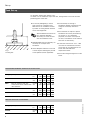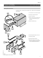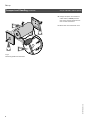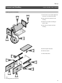
1
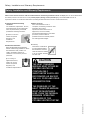
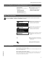
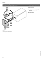
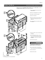
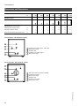
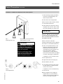
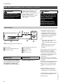
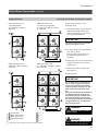
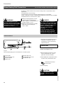
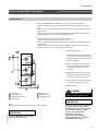
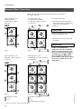
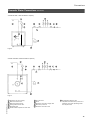
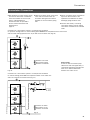
Installation Instructions
Please file in Service Binder
for use by heating contractor
Vitocell 300
EHA Series
Indirect-fired domestic hot water storage tank
42 to 120 USG / 160 to 450 ltr capacity
VITOCELL-H 300
CAUTION
THE HEAT TRANSFER
MEDIUM MUST BE WATER
OR OTHER NON-TOXIC
FLUID HAVING A TOXICITY
RATING OR CLASS OF 1,
AS LISTED IN CLINICAL
TOXICOLOGY OF
COMMERCIAL PRODUCTS,
5TH EDITION.
THE PRESSURE OF THE
HEAT TRANSFER MEDIUM
MUST BE LIMITED TO A
MAXIMUM OF 30 PSIG
BY AN APPROVED SAFETY
OR RELIEF VALVE (SEE
PAGE 2).
IMPORTANT
Read and save these instructions
for future reference.
5167 535 v1.3 07/2008
Safety, Installation and Warranty Requirements
Safety, Installation and Warranty Requirements
Please ensure that this manual is read and understood before commencing installation. Failure to comply with the issues listed below
and details printed in this manual can cause product/property damage, severe personal injury, and/or loss of life. Ensure all
requirements below are understood and fulfilled (including detailed information found in manual subsections).
H Licensed professional heating
contractor
The installation, adjustment, service,
and maintenance of this equipment
must be performed by a licensed
professional heating contractor.
Please see section
entitled “Important
Regulatory and
Installation
Requirements”.
"
H Product documentation
Read all applicable documentation
before commencing installation. Store
documentation near product in a
readily accessible location for
reference in the future by service
personnel.
For a listing of
applicable literature,
please see section
entitled “Important
Regulatory and
Installation Requirements”.
"
H Advice to owner
Once the installation work is
complete, the heating contractor must
familiarize the system
operator/ultimate owner with all
equipment, as well as safety
precautions/requirements, shut-down
procedure, and the need for
professional service annually before
the heating season begins.
H Warranty
Information contained in
this and related product
documentation must be
read and followed. Failure
to do so renders warranty
null and void.
CAUTION
THE HEAT TRANSFER
MEDIUM MUST EITHER BE
POTABLE WATER OR
CONTAIN ONLY
SUBSTANCES WHICH ARE
RECOGNIZED AS SAFE BY
THE U.S. FOOD AND DRUG
ADMINISTRATION.
5167 535 v1.3
THE PRESSURE OF THE
HEAT TRANSFER MEDIUM
MUST BE MAINTAINED
LESS THAN THE NORMAL
MINIMUM OPERATING
PRESSURE OF THE
POTABLE WATER SYSTEM.
2
Contents
Page
Safety
Important Regulatory and Installation Requirements
General Information
About these Instructions
....
4
.......................................................
5
................................................................
5
...............................................................................
6
Transport and Handling
– Removing panels and insulation . . . . . . . . . . . . . . . . . . . . . . . . . . . . . . . . . . . . . .
– Installing panels and insulation . . . . . . . . . . . . . . . . . . . . . . . . . . . . . . . . . . . . . . . .
7
9
Product Information
Set-up
Tank Set-up
Multiple Tank Set-up
Connections
..............................................................
Orientation and Dimensions
.................................................
Control Connections
Sensor well and installation of a
DHW tank temperature sensor or aquastat
.....................
11
12
13
Boiler Water Connections
(heat exchanger connection)
Individual DHW tank . . . . . . . . . . . . . . . . . . . . . . . . . . . . . . . . . . . . . . . . . . . . . . . . . . . . . . . . . . . . . . . 14
Multiple DHW tanks . . . . . . . . . . . . . . . . . . . . . . . . . . . . . . . . . . . . . . . . . . . . . . . . . . . . . . . . . . . . . . . . 15
Steam Heating Connections
(heat exchanger connection)
Individual DHW tank . . . . . . . . . . . . . . . . . . . . . . . . . . . . . . . . . . . . . . . . . . . . . . . . . . . . . . . . . . . . . . . 16
Multiple DHW tanks . . . . . . . . . . . . . . . . . . . . . . . . . . . . . . . . . . . . . . . . . . . . . . . . . . . . . . . . . . . . . . . . 17
..............................................
18
Recirculation Connections
.....................................................
21
Pressure Drop Information
....................................................
22
Domestic Water Connections
Appendix
5167 535 v1.3
Post Installation ...
Start-up information . . . . . . . . . . . . . . . . . . . . . . . . . . . . . . . . . . . . . . . . . . . . . . . . . . . . . . . . . . . . . . . . 23
Service Binder . . . . . . . . . . . . . . . . . . . . . . . . . . . . . . . . . . . . . . . . . . . . . . . . . . . . . . . . . . . . . . . . . . . . . . . . . . . 23
3
Safety
Important Regulatory and Installation Requirements
Codes
The installation of indirect-fired hot
water storage tanks might be governed
by individual local rules and regulations
for this type of product, which must be
observed. The installation of this unit
shall be in accordance with local codes.
Always use latest editions of codes.
In the Commonwealth of
Massachusetts, all plumbing work must
be done by a licensed plumber or
gas-fitter and for gas installations, all
gas piping must be done by a licensed
gas-fitter.”
Mechanical room
Ensure the mechanical room complies
with the requirements of the system
design guideline and/or technical data
manual.
The tank must be installed in a
mechanical room which is never subject
to freezing temperatures.
If not in use and danger of freezing
exists in the mechanical room, ensure
water in tank is drained.
Please carefully read this manual prior
to attempting installation. Any
warranty is null and void if these
instructions are not followed.
This product must be installed
observing not only the information
and instructions provided in the
pertinent product literature (see list),
but also all local, provincial/state
plumbing and building codes, as they
apply to this product and all periphery
equipment.
For information regarding other
Viessmann System Technology
componentry, please reference
documentation of the respective
product.
We offer frequent installation and
service seminars to familiarize our
partners with our products. Please
inquire.
WARNING
If the heating system itself is to be
filled with Glycol or any other
antifreeze, the system fill must be of
non-toxic or food grade antifreeze. In
any circumstance, a non-toxic fluid
must be used. Ensure a copy of the
Material Safety Data Sheet (MSDS) is
supplied to the operator/ultimate
owner of the system.
Ensure main power supply to
equipment, the heating system, and all
external controls has been deactivated.
Close main oil or gas supply valve. Take
precautions in both instances to avoid
accidental activation of power during
service work.
4
The completeness and functionality of
field supplied electrical controls and
components must be verified by the
heating contractor. These include
low-water cut-offs, flow switches (if
used), staging controls, pumps,
motorized valves, air vents,
thermostats, temperature controls, etc.
5167 535 v1.3
Working on the equipment
The installation, adjustment, service,
and maintenance of this equipment
must be done by a licensed professional
heating contractor who is qualified and
experienced in the installation, service,
and maintenance of hot water heating
systems. There are no user serviceable
parts on this equipment.
Safety/General Information
Important Regulatory and Installation Requirements
Technical literature
Literature applicable to all aspects of
the Vitocell:
- Technical Data Manual
- Installation Instructions
- Start-up/Service Instructions
- Operating Instructions
and User’s Information Manual
(Continued)
Leave all literature at the installation
site and advise the system
operator/ultimate owner where the
literature can be found. Contact
Viessmann for additional copies.
About These Instructions
Take note of all symbols and notations intended to draw attention to potential hazards or important product information.
These include ”WARNING”, ”CAUTION”, and ”IMPORTANT”. See below.
WARNING
Indicates an imminently hazardous
situation which, if not avoided, could
result in death, serious injury or
substantial product/property damage.
CAUTION
Indicates an imminently hazardous
situation which, if not avoided, may
result in minor injury or
product/property damage.
IMPORTANT
Warnings draw your attention to the
presence of potential hazards or
important product information.
Cautions draw your attention to the
presence of potential hazards or
important product information.
Helpful hints for installation, operation
or maintenance which pertain to the
product.
This symbol indicates that additional,
pertinent information is to be found in
column three.
This symbol indicates that other
instructions must be referenced.
Product Information
5167 535 v1.3
42 and 53 USG / 160 and 200 ltr capacity
Indirect-fired domestic hot water storage tank with one heat exchanger coil for use
with hot water heating boilers.
92 and 120 USG / 350 and 450 ltr capacity
Indirect-fired domestic hot water storage tank with one heat exchanger coil for use
with hot water heating boilers, commercial heating plants, and low-temperature
heating systems (larger heating surface).
5
Set-up
Tank Set-up
For 92 USG / 350 ltr tank capacity only:
If a boiler is to be installed on top of the tank, arrange boiler to lock into the front
positioning pins of the tank.
H For narrow passageways, remove
lower portion of crating and carry
DHW tank to its installation location
by means of crating boards mounted
on the tank lengthwise.
¾”
20 mm
max: 1½”
35 mm
See Installation Instructions of
the “Transport Handles”
(accessory) to move the tank
into the mechanical room.
min:
Fig 1.
Leveling bolt
H Packaged M 8 bolts are necessary for
the set-up of a multiple tank
installation.
H Leave adequate clearance to the wall
or other objects enabling easy access
to the aquastat (where applicable).
H Locate tank(s) on flooring or
foundation capable of supporting the
weight of the tank(s) filled with
water.
H The tank does not require a special
foundation and can be placed directly
on the floor. If, for cleanliness
purposes, the tank is to be kept off
the floor, a foundation can be used for
each tank or tank battery.
H A minimum clearance of 17¾” / 450
mm must be maintained at the back
of the tank for the installation of the
sensor well and DHW tank
temperature sensor.
H Level tank using leveling bolts on tank
frame.
Recommended installation clearances for service access
Storage capacity
USG
Ltr
42
160
53
200
92
350
120
450
Rear
inches
mm
18
460
18
460
18
460
18
460
May be reduced if rear pipe
inches
connections can be reached with mm
less clearance
12
300
12
300
12
300
12
300
Top
inches
mm
12
300
12
300
12
300
12
300
Front
inches
mm
24
600
24
600
24
600
24
600
Storage capacity
USG
Ltr
42
160
53
200
92
350
120
450
All sides
inches
mm
0
0
0
0
0
0
0
0
Sides
6
5167 535 v1.3
Minimum clearances to combustibles
Set-up
Transport and Handling
only for 120 USG / 450 ltr capacity
Removing panels and insulation
The width of 35¾” / 910 mm can be reduced to 32” / 810 mm by removing panels
and insulation.
1. Turn tank 90° to sit across its pallet.
4.
1.
2. Carefully unhook front panel.
3. Remove insulation.
4. Remove spring clip and carefully pull
sensor of the thermometer out of
tank cap.
5. Remove insulation ring.
5.
3.
2.
8.
6. Pull side panels forward to remove.
7.
9.
7. Unscrew top panel.
8. Unscrew support brackets.
8.
5167 535 v1.3
8.
9. Mark exact position of inner front
panel on top edge of front panel and
on tank insulation using a pencil.
6.
6.
8.
Fig 2.
Removing panels and insulation
7
Set-up
Transport and Handling
(Continued)
only for 120 USG / 450 ltr capacity
10. Using a flat piece of wood and a
rubber mallet, carefully hammer
inner front and rear panels off the
four corners and remove.
11.
11. Move tank into mechanical room.
10.
10.
10.
5167 535 v1.3
Fig 3.
Removing panels and insulation
8
Set-up
Transport and Handling
only for 120 USG / 450 ltr capacity
Installing panels and insulation
1. Place tank on top of pallet again and
turn 90° to sit across the pallet.
4.
1.
8.
2. Push inner front panel onto tank
housing.
3. Position front panel according to
pencil marks.
4. Push inner rear panel onto tank
housing.
3.
2.
5. Fasten support brackets.
6.
6. Install top panel.
7. Install side panels.
5.
5.
5.
5167 535 v1.3
5.
7.
7.
Fig 4.
Installing panels and insulation
9
Set-up
Transport and Handling
(Continued)
only for 120 USG / 450 ltr capacity
8. Mount insulation.
9.
9. Fully insert sensor into opening in
tank cap and secure using
spring-clip.
10. Install insulation.
11. Install front panel.
8.
10.
11.
5167 535 v1.3
Fig 5.
Installing panels and insulation
10
Set-up
Multiple Tank Set-up
only for 92 and 120 USG / 350 and 450 ltr capacity
Two tanks, each with 92 USG / 350 ltr content, and up to three tanks, each with
120 USG / 450 ltr content, may be stacked vertically.
1. Set-up and orient lower tank in its
final location.
5.
2. Remove levelling bolts of top tank.
3. Carefully unhook front panel.
4. Remove insulation.
5. Remove spring clip and carefully pull
sensor of the thermometer out of
tank cap.
6.
6.
6. Pull side panels of top tank forward
to remove.
4.
2.
3.
M8
1.
2.
4.
1. Place top tank on top of bottom tank
and align.
2. Take packaged M 8 bolts, drop in
holes of top tank support brackets
and fasten to bottom tank support
brackets.
3. Reinstall side panels.
IMPORTANT
Install third tank (if applicable) in an
identical fashion as the second tank.
4. Fully insert sensor into opening in
tank cap and secure using spring-clip.
5167 535 v1.3
5. Install insulation.
5.
3.
6. Install front panel.
6.
Fig 6.
Installing tanks in a stacked fashion
11
Connections
Orientation and Dimensions
Storage capacity
USG
Ltr
Number of tanks
42
160
53
200
92
350
120
450
184
700
240
900
360
1350
1
1
1
1
2
2
3
Layout
Connections (individual tank)
Heating water supply/return
∅’’
1
1
11/4
11/4
11/4
11/4
11/4
Domestic cold/hot water
∅’’
3/
4
3/
4
11/4
11/4
11/4
11/4
11/4
Pressure and temperature relief valve
∅’’
3/
4
3/
4
1
11/4
1
11/4
11/4
42 and 53 USG / 160 and 200 ltr capacity
Domestic hot water supply, T&P valve
Boiler water supply
Aquastat well
Domestic cold water supply
Boiler water return
92 and 120 USG / 350 and 450 ltr capacity
5167 535 v1.3
T&P valve (and recirculation tapping)
Domestic hot water
Boiler water supply
Aquastat well
Domestic cold water
Boiler water return
12
Connections
Control Connections
(Continued)
Installation of a DHW tank temperature sensor and/or aquastat
1. Install reducing coupling (included in
Connection Fitting Package). Use
approved pipe sealant.
2. Install sensor well using sealant.
Where Vitotronic 200 or 300 is utilized
to control DHW production:
3. Insert DHW tank temperature sensor
(supplied with Vitotronic 200 or 300)
fully and completely into sensor well.
IMPORTANT
1.
Due to the length of the stainless steel
well (15” / 380 mm), care must be taken
to ensure that the sensing bulb of the
limit is inserted and pushed to the end of
the stainless steel well.
2.
Fig 7.
Installing sensor well
Not present on 42 and 53 USG/
160 and 200 ltr version
WARNING
To ensure optimum, safe operation,
the supplied stainless steel well must
be installed. The well diameter is
large enough to accommodate a wide
variety of sensing bulbs.
Always use spring clip to ensure
proper contact of capillary bulb
against the stainless steel well for
proper sensing/heat transfer!
Where a Vitotronic 100 and a
Viessmann Power/Pump Control Module
are utilized to control DHW production:
4. Insert the extended capillary of the
aquastat (supplied with Viessmann
Power/Pump Control Module, not
illustrated) fully and completely into
sensor well. Mount aquastat
inconspicuously on tank paneling.
Follow instructions below with regard
to sensor and spring clip installation.
... if aquastat is to be mounted remote
from the aquastat well,
5. Align sensor bulb with spring clip.
6. Slide assembly into well.
7. The retention spring clip must press
the bulb properly to ensure surface
contact with the well.
5167 535 v1.3
Fig 8.
Installing aquastat
... if aquastat is to be mounted directly
on the tank well,
8. Mount aquastat with holding clip
supplied directly onto well. Bend
capillary tube into groove opening to
allow for mounting of aquastat.
13
Connections
Boiler Water Connections (heat exchanger connection)
WARNING
The operating aquastat and any
secondary high limit aquastat of the
tank must be set such that the DHW
temperature inside the tank never
exceeds 210°F / 99°C.
H Maximum working pressure on heat
exchanger side up to 220 psig at
392°F / 200°C or a steam pressure of
15 psig at 250°F / 121°C
H Maximum working pressure on DHW
water side of up to 150 psig at
210°F / 99°C
DANGER
Domestic hot water temperatures
over 125°F / 52°C can cause severe
burns instantly or death from scalds.
Children, disabled and elderly are at
highest risk of being scalded.
Feel water before bathing or
showering.
Temperature limiting valves are
available and must be used where
domestic hot water storage tank
temperatures exceed 140°F / 60°C.
Individual DHW tank
1. Pipe together boiler and tank as
illustrated. Connections must be
accessible for service (use factory
supplied adaptors). We recommend
using Viessmann Flexible Piping of
stainless steel (accessory).
Fig 9.
Recommended piping of an individual tank
Vitocell 300
Sensor/Operating aquastat well
Automatic air vent
IMPORTANT
This is a simplified conceptual drawing
only! Piping and necessary componentry
must be field verified. Proper installation
and functionality in the field is the
responsibility of the heating contractor.
Spring-loaded flow-check valve
Circulation pump
Boiler water supply
Boiler
Boiler water return
IMPORTANT
Use hemp and pipe dope on all threaded
stainless steel nipples on tank.
2. For:
- boiler water supply temperatures
over 203°F / 95°C and
- 92 and 120 USG / 350 and 450 ltr
tanks:
Remove plastic supply and return
grommets (grommets are left
threaded).
3. Pipe supply line with an incline and
install componentry as follows:
H flow check valve, to stop gravity
circulation of hot water back to the
boiler when the boiler temperature is
lower than the actual tank
temperature
H automatic air vent, at the high point
from the boiler supply to the tank heat
exchanger
H drain valve, on the boiler return piping
from the tank heat exchanger coil
H isolation valve, on the boiler supply
and boiler return piping to the tank
coil.
5. Install DHW tank temperature sensor
in sensor well (see page 13 or 14).
6. Insulate piping.
14
5167 535 v1.3
4. Protect all domestic hot water
drawpoints from excessive water
temperatures via a tempering valve.
Connections
Boiler Water Connections
(Continued)
Multiple DHW tanks
DHW tank battery with
184 and 240 USG /
700 and 900 ltr capacity
(dual cell)
only for 92 and 120 USG / 350 and 450 ltr capacity
DHW tank battery with
2 x 184 and 2 x 240 USG /
2 x 700 and 2 x 900 ltr capacity
(2×dual cell)
All piping reverse return or use
balancing valves.
1. Pipe together boiler (not shown) and
tanks as illustrated. Connections
must be accessible for service (use
factory supplied adaptors).
IMPORTANT
Use hemp and pipe dope on all threaded
stainless steel nipples on tank.
2. For boiler water supply temperatures
over 203°F / 95°C:
Remove plastic supply and return
grommets (grommets are left
threaded).
DHW tank battery with
1350 USG / 360 ltr capacity
(triple cell)
DHW tank battery with
2 x 1350 USG / 2 x 360 ltr capacity
(2 x triple cell)
3. Pipe supply line with an elevation and
install an automatic air vent at the
highest point.
4. Install boiler sensor in sensor well
(see page 14).
5. Insulate piping.
IMPORTANT
The circulation pump is activated by the
sensor / operating aquastat and by the
control system installed. The operating
aquastat should be mounted on the tank
which receives the boiler water supply
last.
Viessmann recommends the installation of
an additional high limit aquastat in the
main discharge pipe of the DHW system.
This aquastat should be wired in series
with the operating aquastat and should be
set approximately 9°F / 5°C higher than
the operating aquastat.
5167 535 v1.3
WARNING
Vitocell 300
Boiler water supply
Boiler water return
Operating aquastat
*1Pipe
11/4”
2” *1
3” *1
4” *1
5” *1
*1
size for boiler supply and return to heat exchanger.
Install tempering valve(s) to protect
against scalding.
WARNING
Do not stack more than three tanks.
Stack only tanks of identical size.
15
Connections
Steam Heating Side Connections
only for 92 and 120 USG / 350 and 450 ltr capacity
Do not use Vitocell indirect-fired hot water storage tanks in superheated steam
applications.
Use appropriate control strategy.
Control strategy must ensure that the values below are not exceeded.
Install a steam-side control to regulate DHW temperature and ensure that the DHW
temperature does not exceed 210°F / 99°C.
WARNING
The operating aquastat and any
secondary high limit aquastat of the
tank must be set such that the DHW
temperature inside the tank never
exceeds 210°F / 99°C.
H Maximum working pressure on heat
exchanger side up to 220 psig at
392°F / 200°C or a steam pressure of
15 psig at 250°F / 121°C
H Maximum working pressure on DHW
water side of up to 150 psig at
210°F / 99°C
DANGER
Domestic hot water temperatures
over 125°F / 52°C can cause severe
burns instantly or death from scalds.
Children, disabled and elderly are at
highest risk of being scalded.
Feel water before bathing or
showering.
Temperature limiting valves are
available and must be used where
domestic hot water storage tank
temperatures exceed 140°F / 60°C.
Individual DHW tank
1. Pipe steam and condensate lines as
illustrated. Connections must be
accessible for service (use factory
supplied adaptors).
IMPORTANT
Use hemp and pipe dope on all threaded
stainless steel nipples on tank.
Fig 10.
Recommended piping of an individual tank in a steam system
Vitocell 300
Sensor/Aquastat well
Vacuum breaker
Steam valve
Steam supply line
Condensation return line
Condensate trap
2. Remove plastic grommets on tank
where condensate lines connect
(grommets are left threaded).
3. Install DHW tank temperature sensor
in sensor well; install steam valve.
Installation Instructions
Control Valve
4. Insulate piping.
For steam applications, a field
supplied 1” T&P valve must be
utilized.
16
5167 535 v1.3
CAUTION
Connections
Steam Heating Side Connections
only for 92 and 120 USG / 350 and 450 ltr capacity
Multiple DHW tanks
The following installation is also subject to local codes and requirements:
- Install a steam valve and vacuum breaker between steam supply line and each
tank.
Install a drain with a condensate trap at the end of the steam supply line to each
steam valve.
Install a condensate trap on each heat exchanger outlet before connecting all
condensate lines to a common condensate return line.
or
- Install a steam valve in the common steam supply line.
Install a vacuum breaker after the steam valve.
Install a drain with a condensate trap at the end of the steam supply line to each
steam valve.
Install a condensate trap on each heat exchanger outlet before connecting all
condensate lines to a common condensate return line.
All piping reverse return.
1. Pipe together steam and condensate
lines as illustrated. Connections must
be accessible for service (use factory
supplied adaptors).
2. Remove plastic grommets on each
tank where steam and condensate
lines connect (grommets are left
threaded).
3. Install an approved type high limit
aquastat for temperature control of
domestic hot water on each tank.
4. Install aquastat temperature sensor in
sensor well; install steam valve.
5. Insulate piping.
Vitocell 300
Condensate trap
Sensor/Aquastat well
Steam supply
Steam valve
Vacuum breaker
Condensate line
WARNING
Do not stack more than three tanks.
Stack only tanks of identical size.
IMPORTANT
Fig 11.
Recommended piping of a tank battery in a steam system
5167 535 v1.3
IMPORTANT
Use hemp and pipe dope on all threaded
stainless steel nipples on tank.
To ensure uniform heating of domestic
hot water within each tank battery,
install domestic hot water recirculation
as illustrated on pages 21 and 22.
Cap any unused recirculation
connection on each tank.
Follow the control and safety
recommendations of the respective
steam boiler manufacturer.
17
Connections
Domestic Water Connections
Ensure that local rules and regulations regarding this type of product
have been observed.
DHW tank battery with
184 and 240 USG /
700 and 900 ltr capacity
(dual cell)
DHW tank battery with
2 x 184 and 2 x 240 USG /
2 x 700 and 2 x 900 ltr capacity
(2 x dual cell)
All piping reverse return.
1. Pipe boiler and tank as illustrated.
Connections must be accessible for
service (use factory supplied
adaptors).
IMPORTANT
Use hemp and pipe dope on all threaded
stainless steel nipples on tank.
2. Insulate domestic hot water piping
and valves.
IMPORTANT
DHW tank battery with
360 USG / 1350 ltr capacity
(triple cell)
Fig 14.
Fig 13.
DHW tank battery with
2 x 360 USG / 2 x 1350 ltr capacity
(2 x triple cell)
Fig 15.
Domestic hot water
11/4”*1
11/2”*1
*1Pipe
18
size for domestic cold and hot water piping
Domestic cold water
2”*1
21/2”*1
Secondary high limit aquastat
5167 535 v1.3
Fig 12.
In order to avoid temperature
stratification Viessmann recommends
the use of a small recirculation pump
between the DHW supply point
and
the DCW supply point
in multiple
tank arrangements (Figs 14 and 15).
The recirculation pump will only operate
when there is no DHW draw from the
tank batteries.
Connections
Domestic Water Connections
(Continued)
42 and 53 USG / 160 and 200 ltr capacity
Y
Fig 16.
92 and 120 USG / 350 and 450 ltr capacity
5167 535 v1.3
Fig 17.
Domestic hot water supply
DHW recirculation line
DHW recirculation pump
Spring loaded check valve
Discharge pipe
Pressure and temperature relief valve
Shut-off valve
Drain
Domestic cold water supply lines
Back-flow preventer
Domestic cold water inlet
Precharged expansion tank
(required where back-flow preventer is
installed; check local plumbing codes
and requirements)
19
Connections
Domestic Water Connections
(Continued)
Always ensure the use of approved type devices. Safety devices include the following components:
IMPORTANT
Use hemp and pipe dope on all threaded
stainless steel nipples on tank.
H Isolation valves
H Drain valve
H Pressure reducing valve
where required by local jurisdiction
H Drinking water filter
where required by local jurisdiction
H Back-flow preventer
Where backflow preventers are
required, a domestic water expansion
tank installation is required in the cold
water inlet piping before the cold
water enters the tank. The back-flow
device must be installed according to
the manufacturer’s installation
instructions. Observe local codes and
regulations.
H Tempering valve
A tempering valve must be field
installed where storage tank
(domestic hot water temperature)
exceeds local restricted temperatures
or 140°F / 60°C. Check code
requirements.
IMPORTANT
A temperature and pressure relief
valve (T&P relief valve) is supplied
with the tank. The heating contractor
must install the valve on each tank in
a method meeting code requirements.
If local codes require a different relief
valve, substitute the manufacturer’s
supplied valve. The tank is approved
for 100 psig where a CRN is required.
Maximum operating pressure is 150
psig.
The T&P relief valve supplied with the
tank is manufactured by Watts
Industries (Model 40XL-8) set to 100
psi for Canadian installations and set
to 150 psi for US installations (where
applicable). The valve is ASME
pressure steam rated for 998 MBH
and CSA temperature steam rated for
200 MBH. It is tested under ANSI
Z21.22 code for Relief Valves and
Automatic Gas Shut-off Devices for
Hot Water Supply Systems. The relief
temperature is set at 210°F / 99°C.
The valve has a male threaded inlet
and female threaded outlet, both ¾”
sizes.
For steam applications, a field
supplied 1” T&P valve must be
utilized.
Proper installation of the T&P valve
shall include all of the following:
- The T&P valve shall be installed in the
pipe connection point marked TPV in
the tank instruction manual.
- The discharge line from the T&P valve
shall be ¾” / 1.9 cm ∅ and run to a
safe place of discharge approximately
1 ft / 30 cm above the floor, close to
a floor drain.
- The discharge line must be as short
as possible and pitch downward from
the T&P valve and terminate plain.
WARNING
The discharge line for the T&P valve
must be oriented to prevent scalding
of attendants.
- Do not route discharge line to the
outdoors.
- Do not install any type of valve or an
obstruction of any kind between the
tank and the T&P valve, or between
the T&P valve and the discharge line
outlet.
The valve test lever must be operated
at least once per year by the owner to
ensure that waterways are clear. A
licensed professional heating
contractor shall reinspect the T&P
valve at least once every three years.
Failure to inspect can result in unsafe
temperature or pressure build-up,
which can result in death, serious
injury or substantial product/property
damage.
5167 535 v1.3
In situations where a booster pump is
used to maintain DHW pressure,
Viessmann strongly recommends the
installation of an oversized large
expansion tank to ensure longer, less
frequent pump cycles with less severe
pressure gradients. If possible, use
flexible piping before and after booster
pump to isolate system piping from
vibration and shocks.
H Temperature and pressure
relief valve
20
Connections
Recirculation Connections
H Pipe domestic hot water supply piping
with tank as illustrated. Connections
must be accessible for service (use
factory supplied adaptors).
Connection sizes are provided in
section entitled Orientation and
Dimensions on
page 12.
H Install recirculation pump, flow-check
valve and recirculation timer (for
shut-down during off-hours where
feasible) on the recirculation piping
side.
H Gravity circulation of the recirculation
system is restricted due to the
upward-curved domestic hot water
discharge piping inside the tank.
H Connect tank battery to existing
recirculation piping. Cap off unused
recirculation connections of individual
tanks.
Connection of a recirculation system in a multiple tank installation
for systems utilizing boilers or remote heating plants without low temperature boiler return water
and for steam heating operation with 15 psi and one recirculation line (Fig 18.)
Domestic hot water
Recirculation piping
Domestic cold water
Fig. 18.
Saving Energy
A timer on the recirculation pump
reduces the heat loss significantly in
commercial applications during times
when no or reduced demand for
domestic hot water occurs.
5167 535 v1.3
Connection of a recirculation system in a multiple tank installation
for remote heating plants with low temperature boiler return water limit
and/or for multiple recirculation lines (Fig 19.)
Domestic hot water
Recirculation circuit
Domestic cold water
Fig 19.
21
Connections
Recirculation Connections
Recirculation tapping
only for 92 and 120 USG / 350 and 450 ltr capacity
The recirculation tapping on the tank is
also the opening for mounting the
temperature and pressure relief valve
(T&P valve).
Fig 20.
5167 535 v1.3
Pressure and temperature relief
valve discharge
Recirculation connection
If this opening is utilized for
recirculation, extend the stainless steel
nipple on the tank with a brass tee
(field supplied) of the same size as the
stainless steel nipple diameter to
accommodate both connections (see Fig
20).
22
Appendix
Pressure Drop Information
8
11 13 16 21
USGPM
30
8
20
4
10
3.2
8
2.4
2
6
5
1.6
4
1.2
3
Waterflow
8 000
5
12
44 10 000
3
40
6 000
ltr/min
16
35
40 50 60 80
60
50
26
30
24
20
4 000
5 000
20
80
18
22
10
100
32
3 000
1
40
13
0.4
2
200
2 000
0.8
80
9
3
300
800
1.2
120
1 000
4
400
4.4
1.6
500
160
600
5
600
200
3.5
6
2
800
240
500
2.4
1000
2.6
8
mbar
3.2
“ w.c.
10
400
320
2.2
Pressure drop
4
20
Pressure drop
8
Pressure drop on heating water side
(primary circuit)
mbar
“ w.c.
Pressure drop on domestic hot water side
(secondary circuit)
ltr/h
USGPM
Waterflow
42 and 53 USG / 160 and 200 ltr storage capacity
92 and 120 USG / 350 and 450 ltr storage capacity
42 USG /
53 USG /
92 USG /
120 USG
160 ltr storage capacity
200 ltr storage capacity
350 ltr storage capacity
/ 450 ltr storage capacity
23
Appendix
Post Installation ...
Start-up/Service Instructions
DHW Tank
Service Binder
1. File all Parts Lists, Operating and
Service Instructions in the Service
Binder.
Printed on environmentally friendly
(recycled and recyclable) paper.
Start-up information
2. Install a protective hanging case near
the boiler and store the Service
Binder in this location.
Viessmann Manufacturing Company (U.S.) Inc.
45 Access Road
Warwick, Rhode Island • 02886 • USA
Tel. (401) 732-0667 • Fax (401) 732-0590
www.viessmann-us.com • [email protected]
24
Viessmann Manufacturing Company Inc.
750 McMurray Road
Waterloo, Ontario • N2V 2G5 • Canada
Tel. (519) 885-6300 • Fax (519) 885-0887
www.viessmann.ca • [email protected]
5167 535 v1.3
Technical information subject to change without notice.
For a listing of applicable Viessmann
literature, please see Important
Regulatory and Installation
Requirements.