1
Sound Blaster Series
Hardware Programming Guide
Hardware Overview
Digital Sound Processor
Mixer
MIDI Port
License Agreement/Limitation And Disclaimer
Of Warranties
PLEASE NOTE : BY DOWNLOADING AND/OR USING THE SOFTWARE AND/OR MANUAL
ACCOMPANYING THIS LICENSE AGREEMENT, YOU ARE HEREBY AGREEING TO THE
FOLLOWING TERMS AND CONDITIONS:
The software and related written materials, including any instructions for use, are provided on an "AS IS"
basis, without warranty of any kind, express or implied. This disclaimer of warranty expressly includes,
but is not limited to, any implied warranties of merchantability and/or of fitness for a particular purpose.
No oral or written information given by Creative Technology Ltd., its suppliers, distributors, dealers,
employees, or agents, shall create or otherwise enlarge the scope of any warranty hereunder. Licensee
assumes the entire risk as to the quality and the performance of such software and licensee application.
Should the software, and/or Licensee application prove defective, you, as licensee (and not Creative
Technology Ltd., its suppliers, distributors, dealers or agents), assume the entire cost of all necessary
correction, servicing, or repair.
RESTRICTIONS ON USE
Creative Technology Ltd. retains title and ownership of the manual and software as well as ownership of
the copyright in any subsequent copies of the manual and software, irrespective of the form of media on or
in which the manual and software are recorded or fixed. By downloading and/or using this manual and
software, Licensee agrees to be bound to the terms of this agreement and further agrees that :
(1) CREATIVE'S BBS/FTP/COMPUSERVE ARE THE ONLY ONLINE SITES WHERE
USERS MAY DOWNLOAD ELECTRONIC FILES CONTAINING THE MANUAL
AND/OR SOFTWARE,
(2) LICENSEE SHALL USE THE MANUAL AND/OR SOFTWARE ONLY FOR THE
PURPOSE OF DEVELOPING LICENSEE APPLICATIONS COMPATIBLE WITH
CREATIVE’S SOUND BLASTER SERIES OF PRODUCTS, UNLESS OTHERWISE
AGREED TO BY FURTHER WRITTEN AGREEMENT FROM CREATIVE
TECHNOLOGY LTD.; AND,
(3) LICENSEE SHALL NOT DISTRIBUTE OR COPY THE MANUAL FOR ANY REASON
OR BY ANY MEANS (INCLUDING IN ELECTRONIC FORM) OR DISTRIBUTE, COPY,
MODIFY, ADAPT, REVERSE ENGINEER,
TRANSLATE OR PREPARE ANY
DERIVATIVE WORK BASED ON THE MANUAL OR SOFTWARE OR ANY
ELEMENT THEREOF OTHER THAN FOR THE ABOVE SAID PURPOSE, WITHOUT
THE EXPRESS WRITTEN CONSENT OF CREATIVE TECHNOLOGY LTD..
CREATIVE TECHNOLOGY LTD. RESERVES ALL RIGHTS NOT EXPRESSLY
GRANTED TO LICENSEE IN THIS LICENSE AGREEMENT.
LIMITATION OF LIABILITY
In no event will Creative Technology Ltd., or anyone else involved in the creation, production, and/or
delivery of this software product be liable to licensee or any other person or entity for any direct or other
damages, including, without limitation, any interruption of services, lost profits, lost savings, loss of data,
or any other consequential, incidental, special, or punitive damages, arising out of the purchase, use,
inability to use, or operation of the software, and/or licensee application, even if Creative Technology Ltd.
or any authorised Creative Technology Ltd. dealer has been advised of the possibility of such damages.
Licensee accepts said disclaimer as the basis upon which the software is offered at the current price and
acknowledges that the price of the software would be higher in lieu of said disclaimer. Some states do not
allow the limitation or exclusion of liability for incidental or consequential damages so the above
limitations and exclusions may not apply to you.
Information in this document is subject to change without notice. Creative Technology Ltd. shall have no
obligation to update or otherwise correct any errors in the manual and software even if Creative
Technology Ltd. is aware of such errors and Creative Technology Ltd. shall be under no obligation to
provide to Licensee any updates, corrections or bug-fixes which Creative Technology Ltd. may elect to
prepare.
Creative Technology Ltd. does not warrant that the functions contained in the manual and software will be
uninterrupted or error free and Licensee is encouraged to test the software for Licensee's intended use
prior to placing any reliance thereon.
Copyright 1993-1996 by Creative Technology Ltd. All rights reserved.
Sound Blaster, Sound Blaster Pro, Sound Blaster 16, and Wave Blaster are trademarks of Creative
Technology Ltd.
IBM is a registered trademark of International Business Machines Corporation.
MS-DOS is a registered trademark and Windows is a trademark of Microsoft Corporation.
All other products are trademarks or registered trademarks of their respective owners.
Contents
Introduction
What You Should Know...............................................................................................ix
Scope and Manual Organization...................................................................................ix
Document Conventions..................................................................................................x
Determining User's Sound Blaster Card ..................................................................... xii
Determining User's Card Settings.............................................................................. xiii
Chapter 1
Hardware Overview
Anatomy of Sound Blaster Family of Audio Cards.................................................... 1-2
Digital Sound Processor Chip..................................................................... 1-2
Mixer Chip.................................................................................................. 1-3
FM Synthesizer Chip................................................................................... 1-3
Bus Interface Chip....................................................................................... 1-4
Advanced Signal Processor ........................................................................ 1-4
Block Diagrams for Sound Blaster Family of Audio Cards....................................... 1-6
Chapter 2
Introduction to DSP Programming
DSP I/O Addresses ................................................................................................... 2-2
Resetting DSP............................................................................................................ 2-2
Reading from DSP..................................................................................................... 2-3
Writing to DSP .......................................................................................................... 2-4
Handling Interrupts from DSP ................................................................................... 2-4
Sharing of Interrupts.................................................................................... 2-5
Configuring DMA and Interrupt Settings ................................................................... 2-6
Chapter 3
Digitized Sound I/O Programming
Digitized Sound Operation Modes ............................................................................ 3-2
Digitized Sound Data Format...................................................................... 3-2
Digitized Sound I/O Transfer Rate.............................................................. 3-4
Direct-Mode ............................................................................................... 3-4
Single-cycle DMA Mode............................................................................ 3-4
Auto-initialize DMA Mode......................................................................... 3-5
High-Speed DMA Mode............................................................................. 3-6
ADPCM DMA mode................................................................................... 3-6
DSP Digitized Sound I/O Capability........................................................... 3-7
Contents
Sample Procedures ..................................................................................................3-10
General Procedures for a DMA mode Transfer.........................................3-11
Handling the DSP Digitized Sound I/O Interrupt .......................................3-11
8-bit Mono Single-cycle Transfer..............................................................3-12
8-bit Mono Auto-initialize Transfer ..........................................................3-14
8-bit Mono High-Speed Single-cycle Transfer..........................................3-16
8-bit Mono High-Speed Auto-initialize Transfer.......................................3-18
8-bit Stereo High-speed Single-cycle Transfer .........................................3-20
8-bit Stereo High-Speed Auto-initialize Transfer......................................3-22
8-bit or 16-bit Single-cycle Transfer.........................................................3-25
8-bit or 16-bit Auto-initialize Transfer......................................................3-27
Chapter 4
Mixer Chip Programming
Programming Sequence..............................................................................................4-2
CT1335 Mixer ...........................................................................................................4-4
Features .......................................................................................................4-4
Register Functions .......................................................................................4-4
CT1345 Mixer ...........................................................................................................4-6
Features .......................................................................................................4-6
Register Functions .......................................................................................4-7
CT1745 Mixer .........................................................................................................4-10
Features .....................................................................................................4-10
Register Functions .....................................................................................4-11
Chapter 5
MIDI Port I/O Programming
SB-MIDI Mode..........................................................................................................5-2
I/O Addresses..............................................................................................5-2
Sending MIDI Data......................................................................................5-3
Reading MIDI Data......................................................................................5-4
MPU-401 UART Mode..............................................................................................5-5
I/O Addresses..............................................................................................5-5
Checking the Status......................................................................................5-6
Sending a Command ....................................................................................5-7
Sending MIDI Data....................................................................................5-10
Reading MIDI Data....................................................................................5-10
Chapter 6
DSP Commands
Commands by Category..............................................................................................6-2
Command Descriptions..............................................................................................6-5
v
vi
Contents
Appendix A Sound Blaster I/O Address Maps
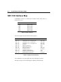
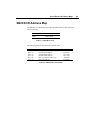
SB1.5 I/O Address Map........................................................................................... A-2
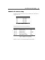
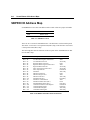
SBMCV I/O Address Map ....................................................................................... A-3
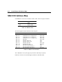
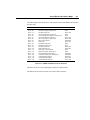
SB2.0 I/O Address Map........................................................................................... A-4
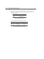
SB2CD I/O Address Map......................................................................................... A-5
SBPRO I/O Address Map ........................................................................................ A-6
SBPRO MCV I/O Address Map............................................................................... A-9
SB16 I/O Address Map.......................................................................................... A-10
Appendix B File Format
Creative Voice File (VOC) Format...........................................................................B-2
Header Block..............................................................................................B-2
Data Block ..................................................................................................B-3
Creative ADPCM Wave Type Format.....................................................................B-12
Appendix C Relevant Information
Index
List of Figures and Tables
Figures
Figure 1-1
Figure 1-2
Figure 1-3
Figure 1-4
Figure 1-5
Figure 3-1
Figure 3-2
Figure 3-3
Figure 3-4
Figure 3-5
Figure 4-1
Figure 4-2
Figure 4-3
Figure 4-4
Figure 4-5
Block Diagram of the Advanced Signal Processor......................................1-4
Block Diagram of the Sound Blaster 2.0......................................................1-6
Block Diagram of the Sound Blaster 2.0 CD Interface ................................1-7
Block Diagram of the Sound Blaster Pro.....................................................1-8
Block Diagram of the Sound Blaster 16 Advanced Signal Processing ........1-9
PCM sample size.........................................................................................3-2
Order of 8-bit mono PCM data....................................................................3-3
Order of 8-bit stereo PCM data...................................................................3-3
Order of 16-bit mono PCM data..................................................................3-3
Order of 16-bit stereo PCM data.................................................................3-3
Register Map of CT1335 Mixer ..................................................................4-4
Register Map of CT1345 Mixer ..................................................................4-7
Register Map of CT1335 Mixer ................................................................4-12
Logical Schematic of the Output Mixing Paths...........................................4-13
Logical Schematic of the Input Mixing Paths .............................................4-14
Tables
Table 2-1
Table 3-1
Table 3-2
Table 3-3
Table 5-1
Table A-1
Table A-2
Table A-3
Table A-4
Table A-5
Table A-6
Table A-7
Table A-8
Table A-9
Table A-10
Table A-11
Table A-12
Table A-13
Table A-14
Table A-15
Table A-16
Table A-17
DSP I/O Ports..............................................................................................2-2
DMA Operation Modes Supported..............................................................3-7
Digitized Sound Output Capabilities ...........................................................3-8
Digitized Sound Input Capabilities..............................................................3-9
MPU-401 I/O Ports......................................................................................5-5
SB1.5 I/O Ports ..........................................................................................A-2
SB1.5 I/O Port Functions............................................................................A-2
SBMCV I/O Ports.......................................................................................A-3
SBMCV I/O Port Functions ........................................................................A-3
SB2.0 I/O Ports ..........................................................................................A-4
SB2.0 I/O Port Functions.............................................................................7-4
SB2CD I/O Ports........................................................................................A-5
SB2CD I/O Port Functions .........................................................................A-5
SBPRO I/O Ports........................................................................................A-6
SBPRO with OPL2 I/O Port Functions.......................................................A-6
SBPRO with OPL3 I/O Port Functions.......................................................A-7
SBPRO MCV I/O Ports ..............................................................................A-8
SBPRO MCV I/O Port Functions................................................................A-8
SB16 I/O Ports ...........................................................................................A-9
SB16 I/O Port Functions.............................................................................A-9
MPU-401 I/O Ports...................................................................................A-10
MPU-401 I/O Port Functions....................................................................A-10
Introduction
This manual covers the hardware programming information for the following Sound
Blaster cards:
Sound Blaster Version 1.5 or earlier (SB1.5)
TM
Sound Blaster for Micro Channel Version (SBMCV)
TM
Sound Blaster Version 2.0 (SB2.0)
TM
Sound Blaster 2.0 CD Interface (SB2CD)
TM
Sound Blaster Pro (SBPRO)
TM
Sound Blaster Pro for Micro Channel Version (SBPRO MCV)
TM
Sound Blaster 16 (SB16)
TM
Sound Blaster 16 with Advanced Signal Processing
TM
TM
This manual documents the programming interface to the main Creative-specific
Sound Blaster hardware components; namely the Digital Sound Processor (DSP),
Mixer chip, and MIDI Port.
The Digital Sound Processor handles digitized sound recording and playback. It
supports 8- or 16-bit digitized sound. Digitized sound I/O can be carried out in mono
or stereo, using Single-cycle or Auto-initialize DMA modes. The Digital Sound
Processor also supports real-time decompression of ADPCM in three compressed
formats: 8 to 4 bits, 8 to 3 bits, and 8 to 2 bits.
The Mixer chip provides volume control of various input and output sources. It also
controls the selection of the recording source.
The MIDI Port on Sound Blaster cards conform to the International MIDI
Association specifications. Through this port, MIDI messages can be transmitted to
and received from external MIDI devices.
Introduction
ix
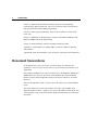
What You Should Know
This manual assumes you are familiar with system level programming on the IBM
PC. This includes programming knowledge of the Direct Memory Access (DMA)
Controller, Programmable Interrupt Controller (PIC), and System Timer. Refer to
"Relevant Information" in the appendix if you need more information on these
subjects.
Familiarity in programming the X86-family of microprocessors is also required,
since assembly code for that range of microprocessors is used in many of the
discussions.
This manual also assumes you are familiar with changing the base I/O address,
interrupt and DMA channels of Sound Blaster cards.
Some chapters in this manual assume additional knowledge on your part. The
introductions to these chapters will list these assumptions.
Scope and Manual Organization
This manual focuses on the Creative-specific hardware programming of the
following:
Digital Sound Processor
Mixer Chip
MIDI Port
Refer to Appendix B, "Relevant Information" if you are interested in programming
the FM chips or the joystick.
This manual is divided into the following chapters:
Chapter 1, "Hardware Overview", gives an overview and functional block diagram of
the Sound Blaster cards.
Chapter 2, "Introduction to DSP Programming", presents the basic knowledge needed
to access the DSP. You may not be able to proceed until you have mastered the
characteristics of the DSP. Read this chapter carefully.
x
Introduction
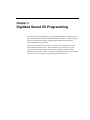
Chapter 3, "Digitized Sound I/O Programming", describes the programming
information for digitized sound I/O. This covers 8-bit and 16-bit, mono and stereo,
high-speed and auto-initialize DMA programming.
Chapter 4, "Mixer Chip Programming", discusses the essentials for control of the
mixer chip.
Chapter 5, "MIDI Port I/O Programming", discusses Sound Blaster MIDI Port and
MPU-401 MIDI UART mode programming.
Chapter 6, "DSP Commands", describes the DSP commands in detail.
Appendix A, "Sound Blaster I/O Address Maps", lists the I/O addresses and their
functionalities.
Appendix B, "Relevant Information", lists the sources of the other relevant materials.
Document Conventions
In this manual, the word "you" refers to you the developer or sometimes your
application. The word "user" does not refer to you, but to the person who uses your
applications.
SB1.5, SB2.0 and SBMCV are referred to collectively as Sound Blaster, SBPRO and
SBPRO MCV are referred to collectively as Sound Blaster Pro, SB16 and Sound
Blaster 16 with Advanced Signal Processing are referred to collectively as Sound
Blaster 16.
The term "Sound Blaster cards" is used to refer to the whole series of Sound Blaster
cards.
The terms "Single-cycle" and "Auto-initialize" are used to refer to DMA mode
digitized sound I/O transfer. "Single-cycle" refers to the Single Transfer Mode, and
"Auto-initialize" refers to the Auto-initialize Single Transfer Mode used in the Intel
data sheets.
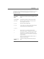
Introduction
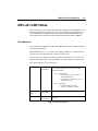
To help you to locate and identify information easily, this manual uses visual cues
and standard text formats. The following typographic conventions are used
throughout this manual:
Example
Description
Write-Buffer
Status
Bold letters are used for keywords or to emphasize certain
words.
CT-VOICE.DRV
All capital letters indicate file names, directory names.
placeholders
Italic letters indicate placeholders. Italics may also be
used to emphasize certain words.
program
This font is used for example codes.
program
.
.
.
fragment
Vertical ellipsis in an example program indicates that part
of the program has been intentionally omitted.
[]
Square brackets in a command line indicate that the
enclosed item is optional. It should not be typed verbatim.
<>
Angle brackets in a command line indicate that you must
provide the actual value of the enclosed item. It should not
be typed verbatim.
/
Slash in a command line indicates an either/or choice. It
should not be typed verbatim.
Sound Blaster Pro
(SBPRO)
Acronyms are usually spelled out the first time they are
used.
xi
xii
Introduction
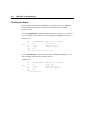
The following DSP version notations will be used in the discussions:
Version Notation
Description
1.xx
This means DSPs with major version number 1.
2.00
This means only the DSPs with version number 2.00.
2.01+
This means DSPs with major version number 2,
version 2.00 is excluded.
3.xx
This means DSPs with major version number 3.
4.xx.
This means DSPs with major version number 4.
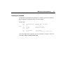
Determining User's Sound Blaster Card
Sound Blaster cards can be distinguished by their DSP version numbers. The table
below lists the Sound Blaster cards and their respective DSP version numbers:
Cards
SB1.5, SBMCV
SB2.0
SBPRO, SBPRO MCV
SB16, Sound Blaster 16 with Advanced Signal Processing
Version Number
1.xx to 2.00
2.01+
3.xx
4.xx
The DSP version can be retrieved by issuing DSP command E1h. This will be
covered in the subsequent chapters.
There are two versions of SBPRO. The difference is in the FM chip used. The earlier
version uses a two-operator FM chip, while the later version uses a four-operator FM
chip. To distinguished them, you can read the value from I/O port 388h, two-operator
cards will return a value of 06h, and four-operator cards will return a value of 00h.
You should determine the actual card used by your user if your application is written
only for a specific card.
Introduction
xiii
Determining User's Card Settings
Most of the Sound Blaster card settings are jumper selectable to avoid conflicts with
other peripheral cards.
To aid the application in determining the settings used by a Sound Blaster card, we
have advocated the use of an environment variable called BLASTER. The user will
set up this environment variable during card installation.
The BLASTER environment variable specifies the base I/O address, interrupt and
DMA channel used by the Sound Blaster card.
The command for setting the BLASTER environment is as follows:
SET BLASTER=A220 I5 D1 [H5 M220 P330]
where:
A
I
D
H
M
P
specifies the Sound Blaster card's base I/O port
specifies the interrupt request line
specifies the 8-bit DMA channel
specifies the 16-bit DMA channel
specifies the mixer chip base I/O port
specifies the MPU-401 base I/O port
Note that there is no space before and after the = (equal) sign, but there must be at
least one space between each setting. Some of the cards may have fewer
environment parameters. For instance, 8-bit sound cards do not have the "Hh"
parameter in the parameter string. If "Mmmm" is not specified, the mixer chip base
I/O port will be the same as the card's base I/O port.
On Sound Blaster 16, 16-bit sound data is usually transfer through 16-bit DMA
channel (specifies on the "Hh" parameter of BLASTER environment variable).
However, the hardware also supports transfer 16-bit sound data via 8-bit DMA
channel. To make this possible, the program SBCONFIG.EXE come with Sound
Blaster 16 package must be run to configure the Sound Blaster 16 appropriately.
When SBCONFIG is run, the BLASTER environment entries "Dd" and "Hh" must be
set such that d and h are the same 8-bit DMA channel number.
We encourage developers to adopt, as standard programming practice, the method of
retrieving the hardware configuration from the BLASTER environment, instead of
scanning the hardware.
Chapter 1
Hardware Overview
This chapter gives an overview of the hardware architecture of the Sound Blaster
family of audio cards. It is meant for developers who intend to do hardware level
programming. Major building blocks of the Sound Blaster family cards and their
functionalities will be discussed.
This chapter also covers the anatomy and block diagrams of Sound Blaster family of
audio cards.
1-2
Hardware Overview
Anatomy of Sound Blaster Family of Audio
Cards
This section describes the major building blocks of the Sound Blaster family of audio
cards. The functionalities and features of the following components will be
presented:
Digital Sound Processor (DSP) chip
Mixer chip
FM Synthesizer chip
Bus Interface chip
Advanced Signal Processor
Digital Sound Processor Chip
The Digital Sound Processor chip is one of the most important components on the
Sound Blaster card. It interprets the DSP commands and then carries out one of the
following tasks:
Performs 8/16 bit Mono/Stereo digitized sound recording and playback
Performs 4:1, 3:1 and 2:1 ADPCM decompression in Sound Blaster mode
Control the sampling rate
Interprets Sound Blaster compatible MIDI and MPU-401 UART mode
commands (Sound Blaster 16 only)
Provides communication path between Host and the Advanced Signal
Processor (Sound Blaster 16 Advanced Signal Processing only)
Provides the Advanced Signal Processor's code downloading (Sound
Blaster 16 Advanced Signal Processing only)
Provides DAC speaker control
Controls various modes of DMA transfer
Hardware Overview
1-3
Different DSP versions are used on various versions of Sound Blaster family cards.
Over the years, the functionality of the DSP has been greatly enhanced. The later
versions of DSP are designed to be downward compatible with its earlier counterparts
with new features introduced. Generally, the DSP versions can be classified under
five majors categories: 1.xx , 2.00 , 2.01+ , 3.xx and 4.xx. In the chapter on
"Introduction to DSP Programming", the essential steps needed to program the DSP
are discussed. In the later chapter on "DSP Commands", various DSP commands are
discussed in details according to their function's category.
Mixer Chip
The main purpose of the mixer chip is to mix signals from different input sources and
to provide software volume control capabilities. All cards in the Sound Blaster
family, except SB2.0 and earlier version of Sound Blaster cards, has mixer chip.
Currently, there are three versions of mixer chip: CT1335 , CT1345 and CT1745.
Each version differs from the other by their ability to accept different number of
sources and to provide volume control resolution. CT1745, the latest version of
mixer chip, can provide a finer resolution of volume control. In the chapter on
"Mixer Chip Programming", each of these mixer chips as well as the included
register maps will be discussed in detail.
FM Synthesizer Chip
The FM synthesizer chip synthesizes the sounds of musical instruments. It tries to
approximate real instrument sounds by applying the Frequency Modulation (FM)
technique to sine waves.
There are two versions of FM synthesizer chips used on Sound Blaster cards;
YAMAHA OPL2 and YAMAHA OPL3. The OPL2 chip is used in earlier versions of
Sound Blaster Pro, SB2.0 and Sound Blaster. The later version of Sound Blaster Pro,
and Sound Blaster 16 use the YAMAHA OPL3 chip.
Please contact the respective vendor for detailed documentation on the FM
synthesizer chip if you are interested on the FM synthesizer chip programming.
1-4
Hardware Overview
Bus Interface Chip
The Bus Interface Chip (CT1336) is responsible for providing handshake signals and
data transfer between the ISA bus and various components on the Sound Blaster card.
On Sound Blaster 16, it provides MPU-401 UART mode compatible MIDI, FIFOs for
digital audio playback and recording, and interrupt channel sharing by three different
processes (8-bit digitized sound, 16-bit digitized sound and MIDI).
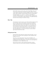
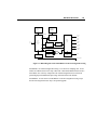
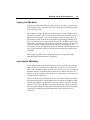
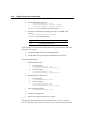
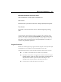
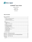
Advanced Signal Processor Chip
The Advanced Signal Processor, used on Sound Blaster 16 Advanced Signal
Processing cards, is a technological breakthrough. It can perform high speed
mathematical processing on digitized sound data. It also provides real-time signal
processing like compression/decompression of sound. The flexibility of the chip is
that it can accept the downloading of algorithms. Below is a simplified block
diagram of this chip:
Clock
Controller
Clocks
Glue Logic
Controller
Interface
AD/DA Data
Interface
Serial
In/Out
Host Data
Interface
Serial
In/Out
Data
RAM
(512 x 16)
Program
RAM
(512 x 32)
DSP Core
Figure 1-1: Block Diagram of the Advanced Signal Processor
Hardware Overview
1-5
These are the main features of the Advanced Signal Processor:
16-bit DSP core
16-bit x 16-bit => 32-bit Multiplier
192 x 16-bit of X-RAM
128 x 16-bit of Y-RAM
512 x 32-bit program memory RAM
512 x 16-bit data memory
Serial I/O for digital audio data
Runs at 12 MIPs
The control of the Advanced Signal Processor, including downloading, is handled by
a device-level driver called CSP.SYS. You can access this device driver via the
Creative Multimedia System (CTMMSYS) driver. Refer to the chapters "Creative
Multimedia System Driver" in the Programmer's Guide and Library Reference
manuals for details.
1-6
Hardware Overview
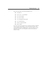
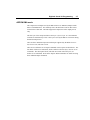
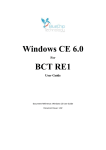
Block Diagrams for Sound Blaster Family of
Audio Cards
After presenting the introduction to the major building blocks of Sound Blaster
cards, we will now present the block diagrams for SB2.0, SB2CD, SBPRO and SB16.
JOYSTICK
PORT
MIDI
PORT
COMMAND/
DATA
MIC
CT1351
DSP
ISA
BUS
CT1336
BUS
INTERFACE
CHIP
AD/DA
FILTER
AGC
LINE IN
CONTROL
FM
SYNTHESIZER
POWER
AMP.
CMS
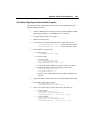
Figure 1-2: Block Diagram of the Sound Blaster 2.0
Note that the CMS chip is optional. The CMS uses Pulse Width Modulation (PWM)
technique to synthesize music. The quality of the sound is not as good as that from a
FM synthesizer, and therefore, has been gradually phased out. All Sound Blaster
cards that is later than SB2.0 does not have the CMS upgrade socket.
Please note the SB2.0 does not contain a mixer chip on board.
SPKR
Hardware Overview
1-7
CD IN
VOICE IN
ISA
BUS
CT1335
Mixer Chip
MUSIC IN
Power
Amp.
ISA
BUS
CD
Interface
SPKR
TO CD-ROM Drive
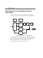
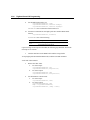
Figure 1-3: Block Diagram of the Sound Blaster 2.0 CD Interface
The SB2CD is the CD-ROM upgrade for SB2.0. It provides a CD-ROM interface
which the SB2.0 does not have. It also includes an audio mixer for software volume
control and a power amplifier.
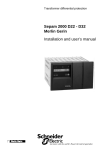
1-8
Hardware Overview
JOYSTICK
PORT
MIDI
PORT
COMMAND/
DATA
FILTER
VOICE DATA
AGC
CT1341
DSP
ISA
BUS
CT1336
BUS
INTERFACE
CHIP
MIC IN
CONTROL
CONTROL
CONTROL
CT1345
MIXER
CHIP
CD IN
LINE IN
FM
SYNTHESIZER
POWER
AMP
CD
INTERFACE
SPKR
CD-ROM DRIVE
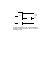
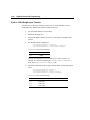
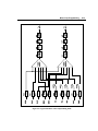
Figure 1-4: Block Diagram of the Sound Blaster Pro
Sound Blaster Pro is a 8-bit stereo sampling card with stereo mixer chip and CD-ROM
interface built in. The DSP has been gradually enhanced to cover wider sampling range.
There are two versions of Sound Blaster Pro. The different is in the FM synthesizer
chip used. The earlier version uses a two-operator FM chip known as OPL2, while the
later version uses a four-operator FM synthesizer chip known as OPL3. The version
with OPL3 is commonly known as Sound Blaster Pro 2.
Hardware Overview
1-9
MIDI PORT
SB and MPU-401
COMPATIBLE
JOYSTICK
PORT
COMMAND/
MIC IN
DATA
CT1741
DSP
(Mono)
CT1745
ISA
BUS
CT1746
BUS
INTERFACE
CHIP
CD IN
(Stereo)
MIXER
CHIP
LINE IN
16-bit
AD/DA
CT1748
CSP
(Stereo)
PC-SPKR
CONTROL
(Mono)
LINE-OUT
(Stereo)
FM
SYNTEHSIZER
CD
INTERFACE
WAVE
BLASTER
POWER
AMP
SPKR
CR-ROM DRIVE
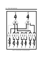
Figure 1-5: Block Diagram of the Sound Blaster 16 Advanced Signal Processing
Sound Blaster 16 Advanced Signal Processing is a 16-bit stereo sampling card. It also
features an enhanced stereo mixer chip. MPU-401 UART mode MIDI interface has also
been added. One of the key component is the Advanced Signal Processor which can
perform high-speed mathematical processing on the data from/to the AD/DA.
Sound Blaster 16 is the same as Sound Blaster 16 Advanced Signal Processing except
the Advanced Signal Processor chip is an optional upgrade.
Chapter 2
Introduction to DSP Programming
This chapter discusses the essentials for programming the Creative Digital Sound
Processor (DSP). The DSP chip handles digitized sound I/O and MIDI operations.
You must read this chapter carefully to ensure you understand the characteristics of
the DSP before you proceed to program digitized sound or MIDI operations.
This chapter covers the following topics:
DSP I/O addresses
Resetting the DSP
Reading from the DSP
Writing to the DSP
Handling interrupt from the DSP
2-2
Introduction to DSP Programming
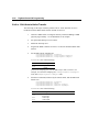
DSP I/O Addresses
The DSP is programmed through four selectable I/O addresses on the Sound Blaster
cards. The following lists the I/O addresses and their functionalities. x represents
the jumper selectable base I/O addresses.
Reset
Used to reset the DSP to its default state.
Write
Command/Data
2x6h
(write only)
2xAh
(read only)
2xCh
(write)
Write-Buffer
Status
2xCh
(read)
Also indicates whether the DSP is ready
to accept commands or data.
Read-Buffer
Status
2xEh
(read only)
Indicates whether there is any in-bound
data available for reading.
Read Data
Used to access in-bound DSP data.
Used to send commands or data to the
DSP.
Table 2-1: DSP I/O Ports
Resetting DSP
The DSP has to be reset before it is first programmed. The reset causes it to perform
an initialization and returns it to its default state. The DSP reset is done through the
Reset port.
After the initialization, the DSP returns a data byte 0AAh at the Read Data port. The
procedure to reset the DSP is as follows:
1.
Write a "1" to the Reset port (2x6h) and wait for 3 microseconds.
2.
Write a "0" to the Reset port.
3.
Poll for a ready byte 0AAh from the Read Data port. You must check the
Read-Buffer Status port to ensure there is data before reading the Read
Data port.
Typically, the DSP takes about 100 microseconds to initialize itself. After this
period of time, if the return value is not 0AAh or there is no data at all, then the
Introduction to DSP Programming
2-3
Sound Blaster card may not be installed or an incorrect I/O address is being used.
You should exit the reset process and declare an error.
The following assembly code fragment shows the process of resetting the DSP:
dx,wSBCBaseAddx
dl,6
; SBC base I/O address 2x0h
; Reset port, 2x6h
mov
out
sub
Delay:
dec
jnz
out
al,1
dx,al
al,al
; Write a 1 to the DSP reset port
;
; Delay loop
al
Delay
dx,al
; Write a 0 to the DSP reset port
sub
Empty:
mov
add
cx,cx
; Maximum of 65536 tries
dx,wSBCBaseAddx
dl,0Eh
; SBC base I/O address 2x0h
; Read-Buffer Status port, 2xEh
in
or
jns
al,dx
al,al
NextAttempt
; Read Read-Buffer Status port
; Data available?
; Bit 7 clear, try again
sub
in
cmp
je
dl,4
al,dx
al,0AAh
ResetOK
;
;
;
;
mov
add
Read Data port, 2xAh
Read in-bound DSP data
Receive success code, 0AAh?
SUCCESS!
NextAttempt:
loop
Empty
; Try again
;***
;*** Failed to reset DSP: Sound Blaster not detected!
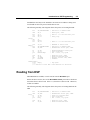
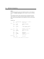
Reading from DSP
When DSP data is available, it can be read in from the Read Data port.
Before the data is read in, bit-7 of the Read-Buffer Status port must be checked to
ensure that there is data to read. If bit-7 is 1, then there is data to read. Otherwise,
no data is available.
The following assembly code fragment shows the process of reading data from the
DSP:
mov
add
dx,wSBCBaseAddx
dl,0Eh
; SBC base I/O address 2x0h
; Read-Buffer Status port, 2xEh
in
or
jns
al,dx
al,al
Busy
; Check for in-bound data
; Data available?
; Bit 7 clear, try again
sub
in
dl,4
al,dx
; Read Data port, 2xAh
; Read in-bound DSP data
Busy:
2-4
Introduction to DSP Programming
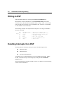
Writing to DSP
DSP commands and data are sent through the Write Command/Data port.
Before data is written to the DSP, bit-7 of the Write-Buffer Status port must be
checked to ensure that the DSP command/data buffer is empty. If bit-7 is 0, the DSP
buffer is empty and is ready to receive commands or data. Otherwise, no commands
or data should be written to the DSP.
The following assembly code fragment shows the process of writing a command or
data byte to the DSP:
mov
add
dx,wSBCBaseAddx
dl,0Ch
; SBC base I/O address 2x0h
; Write-Buffer Status port, 2xCh
in
or
js
al,dx
al,al
Busy
; Read Write-Buffer Status port
; Can write to DSP?
; Bit 7 set, try again
mov
out
al,bData
dx,al
; Get DSP command or data
; Send to DSP
Busy:
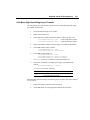
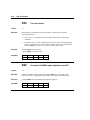
Handling Interrupts from DSP
The DSP generates a hardware interrupt for each of the following processes:
DMA mode ADC
DMA mode DAC
Interrupt mode MIDI input
An interrupt service routine (ISR) has to be set up to handle the interrupts. Within
the ISR, each DSP interrupt is acknowledged by reading the DSP Read-Buffer
Status port once.
The acknowledgment of interrupts on DSP version 4.xx is different; see the following
section for more information.
Introduction to DSP Programming
2-5
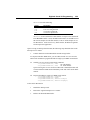
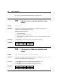
Sharing of Interrupts
With DSP version 4.xx, four interrupts use the same Interrupt Request (IRQ) line.
These are the 8-bit and 16-bit DMA mode digitized sound I/O, Sound Blaster MIDI
(SB-MIDI), and MPU-401 MIDI UART mode interrupts.
The Interrupt Status register, addressed as register 82h on the Mixer register map,
is used by the ISR to determine whether the interrupt is meant for it or for some other
ISR, in which case it should chain to the previous routine.
Reading register 82h is accomplished in the same manner as reading any of the other
mixer registers (see the chapter on "Mixer Chip Programming"). The byte read in
from register 82h is interpreted as follows:
D7
D6
D5
D4
D3
D2
D1
D0
MPU-401
16-bit
DMA-mode
digitized
sound I/O
8-bit
DMA-mode
digitized
sound I/O
SB-MIDI
where the grayed areas denote reserved bits. A bit is set to 1 if the corresponding
interrupt is triggered.
To send an interrupt acknowledgment signal to the DSP, perform a read in from one
of three I/O ports with:
in
al,dx
where register DX has been pre-loaded with
2xEh for 8-bit DMA-mode digitized sound I/O or SB-MIDI
2xFh for 16-bit DMA-mode digitized sound I/O
3x0h for MPU-401
Note that it is not possible to distinguish between 8-bit DMA mode digitized sound
I/O and SB-MIDI interrupts because these two processes share the same interrupt
status bit. It is thus important to avoid running both processes at the same time.
To remain backward compatible, the interrupt acknowledgment of 8-bit DMA mode
digitized sound I/O and SB-MIDI is done via the Read-Buffer Status port of the
DSP.
2-6
Introduction to DSP Programming
The following assembly code fragment illustrates the interrupt handling portion
within a 16-bit DMA mode digitized sound I/O ISR:
mov
add
mov
out
inc
in
test
interrupt?
jz
dx,wSB16BaseAddx
dl,4
al,82h
dx,al
dx
al,dx
al,02h
; SB16 base I/O address 2x0h
; Mixer register address port 2x4h
; Index for Interrupt Status register
; Mixer data port
; Get interrupt status
; 16-bit DMA-mode digitized sound I/O
ChainPreviousISR ; No, chain to previous ISR
;***
;*** 1). Perform your 16-bit DMA digitized sound I/O
instructions
;*** 2). Acknowledge the DSP interrupt; in al,2xFh
;*** 3). Send EOI to the Programmable Interrupt Controller
;***
jmp
ExitISR
ChainPreviousISR:
;***
;*** Chain to previous ISR
ExitISR:
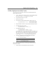
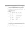
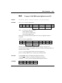
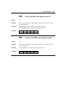
Configuring DMA and Interrupt Settings
With the DSP version 4.xx, the DMA channels Interrupt Request (IRQ) line are
software configurable. The Interrupt Setup register, addressed as register 80h on
the Mixer register map, is used to configure or determine the Interrupt Request line.
The DMA Setup register, addressed as register 81h on the Mixer register map, is
used to configure or determine the DMA channels.
Reading and writing the register 80h and 81h are accomplished in the same manner
as reading and writing any of the other mixer registers (see the chapter "Mixer Chip
Programming").
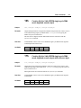
The byte from register 80h is interpreted as follows:
D7
D6
D5
D4
D3
D2
D1
D0
IRQ10
IRQ7
IRQ5
IRQ2
where the grayed areas denote reserved bits.
To configure the IRQ setting, set the corresponding interrupt bit to '1' to select the
IRQ. Note that only a bit can be set on at any one time.
Introduction to DSP Programming
2-7
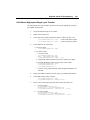
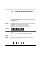
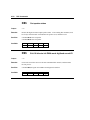
The byte from register 81h is interpreted as follows:
D7
D6
D5
DMA
7
DMA
6
DMA
5
D4
D3
D2
DMA
3
D1
D0
DMA
1
DMA
0
where the grayed areas denote reserved bits.
To configure the DMA channel settings, set the corresponding interrupt bit to '1' to
select the DMA channel. Note that only a bit on the 16-bit DMA channel (DMA5,
DMA6 or DMA7) can be set on at any one time. This applies for the 8-bit DMA
channel (DMA0, DMA1 or DMA3).
DSP version 4.xx also supports the transfer of 16-bit digitized sound data through 8bit DMA channel. To make this possible, set all the 16-bit DMA channel bits to '0'
leaving only an 8-bit DMA channel set.
Note that application should not write to these registers to change the DMA and
interrupt settings as many other system configurations such as BLASTER
environment and Windows SYSTEM.INI file need to be updated when changing
these registers. These registers should only be changed by system software such as
SBCONFIG.EXE that come with Sound Blaster 16 package.
NOTE : Registers 80h and 81h are Read Only for PnP boards.
Chapter 3
Digitized Sound I/O Programming
This chapter discusses the techniques of programming the DSP for digitized sound
I/O and introduces the operational methods and modes available. It assumes that you
have some working knowledge on programming the DMA controller and the
Programmable Interrupt Controller.
This chapter is divided into two sections. The first section describes the various
digitized sound operation modes. The second section provides the step by step
procedures needed to perform the various modes of digitized sound operation
described in the first part. Simple C language I/O port instructions are also included
in the second section to help you use the steps presented effectively.
3-2
Digitized Sound I/O Programming
Digitized Sound Operation Modes
This section describes the digitized sound data format and various digitized sound
operation modes available on the DSP. It covers the following topics:
digitized sound data format
digitized sound I/O transfer rate
direct mode digitized sound I/O
single-cycle DMA mode digitized sound I/O
auto-initialize DMA mode digitized sound I/O
high-speed DMA mode digitized sound I/O
Adaptive Delta Pulse Code Modulation (ADPCM) DMA mode digitized
sound I/O
DSP digitized sound I/O capability
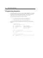
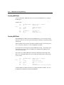
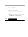
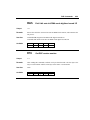
Digitized Sound Data Format
The digitized sound data is in Pulse Code Modulation (PCM) format. For 8-bit PCM
data, each sample is represented by an unsigned byte. For 16-bit PCM data, each
sample is represented by a 16-bit signed value.
The maximum and minimum values for PCM samples of 8-bit and 16-bit sizes are as
follows:
Format
Maximum Value
Minimum Value
Midpoint Value
8-bit PCM
255 (0xFF)
0
128 (0x80)
16-bit PCM
32767 (0x7FFF)
-32768 (-0x8000)
0
Figure 3-1: PCM sample size
Digitized Sound I/O Programming
3-3
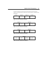
The order of the data varies between 8-bit and 16-bit data, and mono and stereo
formats. The following show the data order for the first four bytes of different PCM
data formats:
sample 1
sample 2
sample 3
sample 4
Channel 0
Channel 0
Channel 0
Channel 0
Figure 3-2: Order of 8-bit mono PCM data
sample 1
Channel 0
(left)
sample 2
Channel 1
(right)
Channel 0
(left)
Channel 1
(right)
Figure 3-3: Order of 8-bit stereo PCM data
sample 1
sample 2
Channel 0
Channel 0
Channel 0
Channel 0
Low-byte
High-byte
Low-byte
High-byte
Figure 3-4: Order of 16-bit mono PCM data
sample 1
Channel 0
(left)
Low-byte
Channel 0
(left)
High-byte
Channel 1
(right)
Low-byte
Figure 3-5: Order of 16-bit stereo PCM data
Channel 1
(right)
High-byte
3-4
Digitized Sound I/O Programming
Digitized Sound I/O Transfer Rate
Other than direct mode, all the digitized sound I/O operation modes require the
transfer rate to be set before any transfer is carried out. To set the transfer rate, you
may either program the DSP with the respective transfer rate Time Constant
(supported by all DSP versions), or program the DSP with the actual sampling rate
(only available on DSP version 4.xx). In the former case, a simple conversion has to
be done first.
Time Constant is the sampling rate representation used by the DSP. It is calculated
as follows:
Time Constant = 65536 - (256 000 000/(channels * sampling rate))
The channels parameter is 1 for mono and 2 for stereo.
Only the high byte of the result is used to program the DSP. Refer to the chapter on
"DSP commands" for the commands to set the digitized sound I/O transfer rate.
Direct Mode
Direct mode digitized sound I/O should be used when direct data input from or output
to the DSP is required.
Under direct mode, only mono 8-bit unsigned PCM data transfer is supported. The
data transfer rate of direct mode is controlled by the application program itself.
Usually, the timer interrupt is used to facilitate this implementation. The frequency
of the timer interrupt is reprogrammed so that it interrupts at the number of times
needed for that particular transfer rate. A new timer interrupt service routine is used
to read the in-bound data from or write the out-bound data to the DSP.
There is no minimum sampling rate in this case. The maximum depends on how fast
the timer interrupt can be programmed, and on how fast the interrupt service routine
can service the interrupt.
Refer to the chapter "DSP Commands" for details on using the direct mode digitized
sound I/O commands.
Digitized Sound I/O Programming
3-5
Single-cycle DMA Mode
In single-cycle DMA mode digitized sound I/O transfer, the DSP is programmed to
make one transfer only. The DSP will generate an interrupt to signal the application
at the end of the transfer.
Due to DMA constraints, the digitized sound data transfer cannot straddle a 64 KB
physical page boundary. Thus, to transfer digitized sound data that reside across a 64
KB physical page boundary, it has to be divided into sub-blocks within a physical
page boundary. Each sub-block must not straddle the physical page boundary and
may be of different sizes (but not more than 64 KB each). The DMA controller and
DSP are then programmed to transfer the data sub-block by sub-block. At the end of
a sub-block transfer, the DSP will generate an interrupt to the application. On
receiving the interrupt, the application reprograms the DMA controller and DSP with
the size of the subsequent sub-block. All sub-blocks are transferred until the data is
exhausted.
Under single-cycle DMA mode, 8-bit unsigned PCM, 16-bit signed PCM, and
ADPCM compressed data transfers are supported.
Auto-initialize DMA Mode
In auto-initialize DMA mode digitized sound I/O transfer, the DMA controller and
DSP need only be programmed once with the block transfer size for the transfer to
begin. When the DMA controller's transfer count "rolls over" from zero to FFFF hex,
the DMA controller will automatically reload the transfer address and count. The
DSP will generate interrupts to the application at constant intervals, according to the
programmed block transfer size.
Usually, the double-buffering method is used for auto-initialize DMA mode transfer.
The application allocates a stationary DMA buffer which must not straddle a 64 KB
physical page boundary. The DSP block transfer size is then set to half of the DMA
buffer size. After every DSP block size transfer, the DSP will generate an interrupt.
On receiving the interrupt, the application can then transfer data to/from (depending
on playback/recording) that half of the DMA buffer whose data has just been
transferred.
3-6
Digitized Sound I/O Programming
There are two ways to terminate auto-initialize DMA mode transfer:
1.
Program the DSP to switch to single-cycle DMA mode transfer. At the
end of the current block transfer, the DSP will exit from auto-initialize
DMA mode and continue to transfer using the specified single-cycle DMA
mode.
2.
Send the exit auto-initialize command; the DSP will exit auto-initialize
DMA mode at the end of current block and terminate the transfer.
Under auto-initialize DMA mode, 8-bit unsigned PCM, 16-bit signed PCM, and
ADPCM compressed data transfers are supported.
Auto-initialize DMA mode is crucial when dealing with high data rates. To give you
some idea of the numbers involved, CD-quality sound (16-bit stereo at 44.1 kHz)
involves transferring data at a rate of 176.4 KB/s. Under these conditions, using singlecycle DMA mode would produce less than optimal sound quality because of the time
needed to reprogram the DMA and DSP to start transferring a new block at the end of
every block of data. The delay between the blocks (though it may be brief), is enough to
distort the sound.
High-Speed DMA Mode
For non high-speed DMA mode, the DSP operates in the command and data modes.
That is, the DSP is able to accept and execute commands that are sent to the DSP
Command/Data port. Using this mode, the DSP can only support data transfer up to a
certain sampling rate. To go beyond that, the DSP has to be switched to high-speed
DMA mode.
Under high-speed DMA mode, the DSP will only perform data transfer. It will not
accept further commands that are sent to the Command/Data port.
Both single-cycle and auto-initialize DMA modes are available for the high-speed
DMA mode. For high-speed single-cycle DMA mode, the DSP will exit high-speed
DMA mode automatically at the end of transfer. For high-speed auto-initialize DMA
mode, a DSP reset is needed to exit high-speed DMA mode.
The DSP reset command behaves differently while the DSP is in high-speed DMA
mode. It terminates high-speed DMA mode and restores all the DSP parameters to
their states prior to entering the high-speed DMA mode.
High-speed DMA mode supports both mono and stereo 8-bit unsigned PCM data.
ADPCM compressed data is not supported.
Digitized Sound I/O Programming
3-7
ADPCM DMA mode
The compression technique used by the DSP is known as ADPCM (Adaptive Delta
Pulse Code Modulation). This technique stores the difference between data values
instead of the actual data. The DSP supports decompression in the output process
only.
The first byte of the compressed data is always a reference byte. It is not ADPCM
code but an actual data byte value. This byte is used by the DSP as a reference during
the data decompression.
There are three ADPCM compression techniques supported by the DSP: 8-bit to 2bit, 8-bit to 3-bit, and 8-bit to 4-bit.
There are two different sets of output commands used to operate on data blocks. The
first block of data to be transferred, which contains a reference byte, uses one set of
commands. The subsequent blocks, which do not contain reference bytes, use
another set of commands. Refer to the chapter "DSP commands" for details on using
these ADPCM output commands.
3-8
Digitized Sound I/O Programming
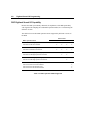
DSP Digitized Sound I/O Capability
Because the DSP is periodically enhanced, the capabilities of the DSP particularly
with regard to the sampling rates and DMA operation modes, have varied among the
different versions.
The table below lists the DMA operation modes supported by different versions of
the DSP:
DMA Operation Mode
DSP Version
2.01+
3.xx
1.xx
2.00
8-bit Mono PCM Single-cycle
8-bit Mono PCM Auto-initialize
9
9
9
9
9
9
9
9
9
8-bit Mono ADPCM Single-cycle
8-bit Mono ADPCM Auto-initialize
9
9
9
9
9
9
9
9
9
9
9
9
9
8-bit Mono PCM High-Speed Single-cycle
8-bit Mono PCM High-Speed Auto-initialize
8-bit Stereo PCM High-Speed Single-cycle
8-bit Stereo PCM High-Speed Auto-initialize
8-bit/16-bit Mono PCM Single-cycle
8-bit/16-bit Mono PCM Auto-initialize
8-bit/16-bit Stereo PCM Single-cycle
8-bit/16-bit Stereo PCM Auto-initialize
Table 3-1: DMA Operation Modes Supported
4.xx
9
9
9
9
9
9
Digitized Sound I/O Programming
3-9
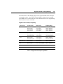
The tables below list the sampling ranges for the supported DMA modes among the
various DSP versions. Normal on the "Transfer Mode" column refers to non highspeed DMA mode. You must take note of the information below when programming
for the different versions of the DSP.
Digitized Sound Output Capability
DSP Version
Transfer Mode
Data Format
Sampling Range
4.xx
Mono/Normal
Mono/Normal
Stereo/Normal
Stereo/Normal
8-bit unsigned
16-bit signed
8-bit unsigned
16-bit signed
5000 to 44100 Hz
5000 to 44100 Hz
5000 to 44100 Hz
5000 to 44100 Hz
3.xx
Mono/Normal
Mono/High-Speed
Stereo/High-Speed
8-bit unsigned
8-bit unsigned
8-bit unsigned
4000 to 23000 Hz
23000 to 44100 Hz
11025 and 22050 Hz
2.01+
Mono/Normal
Mono/High-Speed
8-bit unsigned
8-bit unsigned
4000 to 23000 Hz
23000 to 44100 Hz
2.00 and 1.xx
Mono/Normal
8-bit unsigned
4000 to 23000 Hz
All
Mono/Normal
8 bit to 4 bit ADPCM
4000 to 12000 Hz
All
Mono/Normal
8 bit to 3 bit ADPCM
4000 to 13000 Hz
All
Mono/Normal
8 bit to 2 bit ADPCM
4000 to 11000 Hz
Table 3-2: Digitized Sound Output Capabilities
3-10
Digitized Sound I/O Programming
Digitized Sound Input Capability
DSP Version
Transfer Mode
Data Format
Sampling Range
4.xx
Mono/Normal
Mono/Normal
Stereo/Normal
Stereo/Normal
8-bit unsigned
16-bit signed
8-bit unsigned
16-bit signed
5000 to 44100 Hz
5000 to 44100 Hz
5000 to 44100 Hz
5000 to 44100 Hz
3.xx
Mono/Normal
Mono/High-Speed
Stereo/High-Speed
8-bit unsigned
8-bit unsigned
8-bit unsigned
4000 to 23000 Hz
23000 to 44100 Hz
11025 and 22050 Hz
2.01+
Mono/Normal
Mono/High-Speed
8-bit unsigned
8-bit unsigned
4000 to 13000 Hz
13000 to 15000 Hz
2.00 and 1.xx
Mono/Normal
8-bit unsigned
4000 to 13000 Hz
Table 3-3: Digitized Sound Input Capabilities
Digitized Sound I/O Programming
3-11
Sample Procedures
This section provides step by step procedures needed to perform the various DMA
modes of digitized sound operations described in the first section.
It covers the following sample procedures:
General procedures for a DMA mode transfer
Handling the DSP digitized sound I/O interrupt
8-bit mono PCM or ADPCM single-cycle DMA mode transfer
8-bit mono PCM or ADPCM auto-initialize DMA mode transfer
8-bit mono PCM high-speed single-cycle DMA mode transfer
8-bit mono PCM high-speed auto-initialize DMA mode transfer
8-bit stereo PCM high-speed single-cycle DMA mode transfer
8-bit stereo PCM high-speed auto-initialize DMA mode transfer
8-bit or 16-bit PCM single-cycle DMA mode transfer
8-bit or 16-bit PCM auto-initialize DMA mode transfer
To help you utilize the sample procedures more effectively, we have also included
simple C language I/O port instructions along with the discussions. In order to focus
on the key steps involved, the checking of the status ports before reading from and
writing to the DSP has been deliberately omitted. In your actual program, you must
check the status ports. Refer to the chapter "Introduction to DSP Programming" for
the details on reading from and writing to the DSP.
Before you continue, you should have read earlier section and have yourself familiar
with digitized sound data format and the transfer rate (time constant).
3-12
Digitized Sound I/O Programming
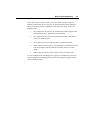
General Procedures for a DMA mode Transfer
The general steps for programming the DSP for digitized sound data transfer in DMA
mode is as follows:
1.
Set up the interrupt service routine.
2.
Program the DMA controller.
3.
Program the DSP sampling rate.
4.
Program the DSP with the DMA transfer mode and length to start I/O
transfer.
5.
Service DSP interrupts.
6.
Restore the original interrupt service routine.
Handling the DSP Digitized Sound I/O Interrupt
The DSP generates an interrupt at the end of each DSP block transfer. The following
lists the general actions needed in the interrupt service routine to handle the
interrupt:
1.
Preserve machine status.
2.
Goto (5) if no more data blocks to transfer.
Depending on the operation mode, perform 3a and 4a if you are using singlecycle mode or 3b and 4b if you are using auto-initialize mode.
3a.
4a.
Program the DMA controller for the next block.
Program the DSP for the next block.
3b.
4b.
Transfer data between the DMA buffer and storage buffer.
If you wish to quit, send the exit command here.
5.
Acknowledge the DSP interrupt.
6.
Output the EOI command (End of Interrupt) to the interrupt controller.
7.
Restore machine status.
8.
Execute an IRET.
Digitized Sound I/O Programming
3-13
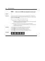
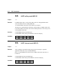
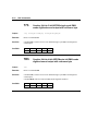
8-bit Mono Single-cycle Transfer
The following are the steps needed to perform 8-bit mono PCM and ADPCM singlecycle DMA mode transfer:
1.
Set up the DSP interrupt service routine.
2.
Enable the interrupt used.
3.
Turn on the DAC speaker for digitized output. Otherwise, turn it off.
to turn off the DAC speaker
outp(wSBCBaseAddx+0xC, 0xD3)
to turn on the DAC speaker
outp(wSBCBaseAddx+0xC, 0xD1)
4.
Program the DMA controller for 8-bit single-cycle DMA mode transfer.
5.
Set the DSP transfer Time Constant.
outp(wSBCBaseAddx+0xC, 0x40)
outp(wSBCBaseAddx+0xC, bTimeConstant)
6.
Send an I/O command followed by data transfer count.
outp(wSBCBaseAddx+0xC, bCommand)
outp(wSBCBaseAddx+0xC, wLength.LowByte)
outp(wSBCBaseAddx+0xC, wLength.HighByte)
bCommand is one of the following:
bCommand
24h
14h
75h
77h
17h
Description
8-bit PCM input
8-bit PCM output
8-bit to 4-bit ADPCM output with reference byte
8-bit to 3-bit ADPCM output with reference byte
8-bit to 2-bit ADPCM output with reference byte
wLength is one less than the actual number of bytes to be transferred.
For example, to transfer 8KB of 8-bit PCM data,
wLength = 2000h - 1 = 1FFFh
Hence, wLength.LowByte = 0FFh and wLength.HighByte = 1Fh.
The transfer begins here. The DSP will generate an interrupt after transferring the
programmed number of bytes.
3-14
Digitized Sound I/O Programming
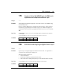
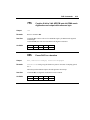
When the DSP sends an interrupt, the following steps should be done in the interrupt
service routine:
1.
Program the DMA controller for the next block.
2.
Program the DSP for the next block.
outp(wSBCBaseAddx+0xC, bCommand)
outp(wSBCBaseAddx+0xC, wLength.LowByte)
outp(wSBCBaseAddx+0xC, wLength.HighByte)
bCommand is one of the following:
bCommand
24h
14h
74h
76h
16h
Description
8-bit PCM input
8-bit PCM output
8 bit to 4 bit ADPCM output without reference byte
8 bit to 3 bit ADPCM output without reference byte
8 bit to 2 bit ADPCM output without reference byte
Please note that for ADPCM output, subsequent data block transfers must
be programmed using different commands; specifically those that do not
take a reference byte.
At the end of data transfer:
1.
Turn off the DAC speaker.
outp(wSBCBaseAddx+0xC, 0xD3)
2.
Disable the interrupt used.
3.
Restore the original interrupt service routine.
Digitized Sound I/O Programming
3-15
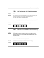
8-bit Mono Auto-initialize Transfer
The following are the steps needed to perform 8-bit mono PCM and ADPCM
auto-initialize DMA mode transfer:
1.
Allocate a DMA buffer in contiguous memory without straddling a 64KB
physical page boundary. Use an 8KB buffer as an example.
2.
Set up the DSP interrupt service routine.
3.
Enable the interrupt used.
4.
Turn on the DAC speaker for digitized output. Otherwise, turn it off.
to turn off the DAC speaker
outp(wSBCBaseAddx+0xC, 0xD3)
to turn on the DAC speaker
outp(wSBCBaseAddx+0xC, 0xD1)
5.
Program the DMA controller for 8-bit auto-initialize DMA mode transfer.
6.
Set the DSP transfer Time Constant.
outp(wSBCBaseAddx+0xC, 0x40)
outp(wSBCBaseAddx+0xC, bTimeConstant)
7.
Set the DSP block transfer size.
outp(wSBCBaseAddx+0xC, 0x48)
outp(wSBCBaseAddx+0xC, wBlkSize.LowByte)
outp(wSBCBaseAddx+0xC, wBlkSize.HighByte)
If an 8KB DMA buffer is used, the DSP block transfer size should be set to
4KB. At the end of every 4KB transfer, the DSP will generate an interrupt
to the application until the exit auto-initialize DMA mode command is
received. Again, wBlkSize is one less than the actual transfer size.
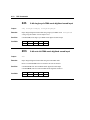
8.
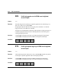
Send an I/O command to start auto-initialize DMA mode transfer.
outp(wSBCBaseAddx+0xC, bCommand)
bCommand is one of the following:
bCommand
2Ch
1Ch
7Dh
7Fh
1Fh
Description
8-bit PCM input
8-bit PCM output
8-bit to 4-bit ADPCM output with reference byte
8-bit to 3-bit ADPCM output with reference byte
8-bit to 2-bit ADPCM output with reference byte
3-16
Digitized Sound I/O Programming
When the DSP sends an interrupt, the following steps should be done in the interrupt
service routine:
1.
Transfer data between the DMA buffer and the storage buffer.
To stop auto-initialize DMA mode, you can either send the exit auto-initialize
DMA mode command or program the DSP for single-cycle DMA mode transfer.
2a. Send the exit auto-initialize DMA command.
outp(wSBCBaseAddx+0xC, 0xDA)
Upon receiving the exit auto-initialize DMA mode command, the DSP will
exit auto-initialize DMA mode immediately at the end of the current block
transfer.
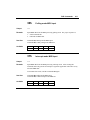
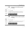
2b. Program the DSP for single-cycle DMA mode transfer.
outp(wSBCBaseAddx+0xC, bCommand)
outp(wSBCBaseAddx+0xC, wLength.LowByte)
outp(wSBCBaseAddx+0xC, wLength.HighByte)
bCommand is one of the following:
bCommand
24h
14h
74h
76h
16h
Description
8-bit PCM input
8-bit PCM output
8 bit to 4 bit ADPCM output without reference byte
8 bit to 3 bit ADPCM output without reference byte
8 bit to 2 bit ADPCM output without reference byte
At the end of data transfer:
1.
Turn off the DAC speaker.
outp(wSBCBaseAddx+0xC, 0xD3)
2.
Disable the interrupt used.
3.
Restore the original interrupt service routine.
4.
Release the allocated DMA buffer.
Digitized Sound I/O Programming
3-17
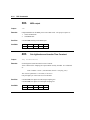
8-bit Mono High-Speed Single-cycle Transfer
The following are the steps needed to perform 8-bit mono PCM high-speed singlecycle DMA mode transfer:
1.
Set up the DSP interrupt service routine.
2.
Enable the interrupt used.
3.
Turn on the DAC speaker for digitized output. Otherwise, turn it off.
to turn off the DAC speaker
outp(wSBCBaseAddx+0xC, 0xD3)
to turn on the DAC speaker
outp(wSBCBaseAddx+0xC, 0xD1)
4.
Program the DMA controller for 8-bit single-cycle DMA mode transfer.
5.
Set the DSP transfer Time Constant.
outp(wSBCBaseAddx+0xC, 0x40)
outp(wSBCBaseAddx+0xC, bTimeConstant)
6.
Set the DSP transfer block size.
outp(wSBCBaseAddx+0xC, 0x48)
outp(wSBCBaseAddx+0xC, wBlkSize.LowByte)
outp(wSBCBaseAddx+0xC, wBlkSize.HighByte)
wBlkSize is one byte less than the actual data transfer size.
7.
Send an I/O command to start high-speed single-cycle DMA mode
transfer.
outp(wSBCBaseAddx+0xC, bCommand)
bCommand is one of the following:
bCommand
99h
91h
Description
8-bit PCM high-speed input
8-bit PCM high-speed output
When the DSP sends an interrupt, the following steps should be done in the interrupt
service routine:
1.
Program the DMA controller for the next block.
2.
Set the DSP block size and program the DSP for the next block.
3-18
Digitized Sound I/O Programming
At the end of data transfer:
1.
Turn off the DAC speaker.
outp(wSBCBaseAddx+0xC, 0xD3)
2.
Disable the interrupt used.
3.
Restore the original interrupt service routine.
During high-speed DMA mode data I/O, the DSP will not accept any commands.
Hence, to stop data transfer before the end of a block, send the reset DSP command.
Digitized Sound I/O Programming
3-19
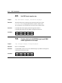
8-bit Mono High-Speed Auto-initialize Transfer
The following are the steps needed to perform 8-bit mono PCM high-speed autoinitialize DMA mode transfer:
1.
Allocate a DMA buffer in contiguous memory without straddling a 64KB
physical page boundary. Use an 8KB buffer as an example.
2.
Set up the DSP interrupt service routine.
3.
Enable the interrupt used.
4.
Turn on the DAC speaker for digitized output. Otherwise, turn it off.
to turn off the DAC speaker
outp(wSBCBaseAddx+0xC, 0xD3)
to turn on the DAC speaker
outp(wSBCBaseAddx+0xC, 0xD1)
5.
Program the DMA controller for 8-bit auto-initialize DMA mode transfer.
6.
Set the DSP transfer Time Constant.
outp(wSBCBaseAddx+0xC, 0x40)
outp(wSBCBaseAddx+0xC, bTimeConstant)
7.
Set the DSP block transfer size.
outp(wSBCBaseAddx+0xC, 0x48)
outp(wSBCBaseAddx+0xC, wBlkSize.LowByte)
outp(wSBCBaseAddx+0xC, wBlkSize.HighByte)
If an 8KB DMA buffer is used, the DSP block transfer size should be set to
4KB. At the end of every 4KB transfer, the DSP will generate an interrupt
to the application until the exit auto-initialize DMA mode command is
received. Again, wBlkSize is one less than the actual transfer size.
8.
Send an I/O command to start auto-initialize DMA mode transfer.
outp(wSBCBaseAddx+0xC, bCommand)
bCommand is one of the following:
bCommand
98h
90h
Description
8-bit PCM High-speed input
8-bit PCM High-speed output
When the DSP sends an DSP interrupt, the following step should be done in the
interrupt service routine:
1.
Transfer data between the DMA buffer and the storage buffer.
3-20
Digitized Sound I/O Programming
To stop high-speed auto-initialize DMA mode, send the reset DSP command.
At the end of data transfer:
1.
Turn off the DAC speaker.
outp(wSBCBaseAddx+0xC, 0xD3)
2.
Disable the interrupt used.
3.
Restore the original interrupt service routine.
4.
Release the allocated DMA buffer.
Digitized Sound I/O Programming
3-21
8-bit Stereo High-speed Single-cycle Transfer
The following are the steps needed to perform 8-bit stereo PCM high-speed singlecycle DMA mode transfer:
1.
Set up the DSP interrupt service routine.
2.
Enable the interrupt used.
3.
Turn on the DAC speaker for digitized output. Otherwise, turn it off.
to turn off the DAC speaker
outp(wSBCBaseAddx+0xC, 0xD3)
to turn on the DAC speaker
outp(wSBCBaseAddx+0xC, 0xD1)
4.
Set the hardware to stereo mode.
a. For stereo input:
outp(wSBCBaseAddx+0xC, 0xA8)
b. For stereo output:
i. Set stereo mode.
outp(wSBCBaseAddx+0x4, 0xE)
bTmp = inp(wSBCBaseAddx+0x5)
outp(wSBCBaseAddx+0x5, (bTmp | 0x2))
ii. Program the DMA controller for one byte single-cycle output.
iii. Program the DSP to output one silent byte (value 0x80).
outp(wSBCBaseAddx+0xC, 0x14)
outp(wSBCBaseAddx+0xC, 0)
outp(wSBCBaseAddx+0xC, 0)
iv Upon receiving a DSP interrupt, acknowledge the DSP then exit
the ISR.
5.
Program the DMA controller for 8-bit single-cycle DMA mode transfer.
6.
Set the DSP transfer Time Constant.
outp(wSBCBaseAddx+0xC, 0x40)
outp(wSBCBaseAddx+0xC, bTimeConstant)
7.
Preserve the current input and output filter status, then turn it off.
a.
For stereo input:
outp(wSBCBaseAddx+0x4, 0xC)
bInputFilter = inp(wSBCBaseAddx+0x5)
outp(wSBCBaseAddx+0x5, (bInputFilter | 0x20))
b.
For stereo output:
outp(wSBCBaseAddx+0x4, 0xE)
bOutputFilter = inp(wSBCBaseAddx+0x5)
outp(wSBCBaseAddx+0x5, (bOutputFilter | 0x20))
3-22
Digitized Sound I/O Programming
8.
Set the DSP block transfer size.
outp(wSBCBaseAddx+0xC, 0x48)
outp(wSBCBaseAddx+0xC, wBlkSize.LowByte)
outp(wSBCBaseAddx+0xC, wBlkSize.HighByte)
wBlkSize is one less than the actual transfer size.
9.
Send an I/O command to start high-speed single-cycle DMA mode
transfer.
outp(wSBCBaseAddx+0xC, bCommand)
bCommand is one of the following:
bCommand
99h
91h
Description
8-bit PCM high-speed input
8-bit PCM high-speed output
Upon receiving an interrupt from the DSP, the following steps should be done in the
interrupt service routine:
1.
Program the DMA controller for subsequent block.
2.
Set the DSP block size and program the DSP for the next block.
At the end of data transfer:
1.
Restore the filter status.
a.
For stereo input:
outp(wSBCBaseAddx+0x4, 0xC)
outp(wSBCBaseAddx+0x5, bInputFilter)
b.
For stereo output:
outp(wSBCBaseAddx+0x4, 0xE)
outp(wSBCBaseAddx+0x5, bOutputFilter)
2.
Set the hardware to mono mode.
a.
For stereo input:
outp(wSBCBaseAddx+0xC, 0xA0)
b.
For stereo output:
outp(wSBCBaseAddx+0x4, 0xE)
bTmp = inp(wSBCBaseAddx+0x5)
outp(wSBCBaseAddx+0x5, (bTmp & 0xFD))
3.
Turn off the DAC speaker.
outp(wSBCBaseAddx+0xC, 0xD3)
4.
Disable the interrupt used.
5.
Restore the original interrupt service routine.
During high-speed DMA mode data I/O, the DSP will not accept any commands.
Hence, to stop data transfer before the end of a block, send the reset DSP command.
Digitized Sound I/O Programming
3-23
8-bit Stereo High-Speed Auto-initialize Transfer
The following are the steps needed to perform 8-bit stereo PCM high-speed autoinitialize DMA mode transfer:
1.
Allocate a DMA buffer in contiguous memory without straddling a 64KB
physical page boundary. Use an 8KB buffer as an example.
2.
Set up the DSP interrupt service routine.
3.
Enable the interrupt used.
4.
Turn on the DAC speaker for digitized output. Otherwise, turn it off.
to turn off the DAC speaker
outp(wSBCBaseAddx+0xC, 0xD3)
to turn on the DAC speaker
outp(wSBCBaseAddx+0xC, 0xD1)
5.
Set the hardware to stereo mode.
a. For stereo input:
outp(wSBCBaseAddx+0xC, 0xA8)
b. For stereo output:
i. Set stereo mode.
outp(wSBCBaseAddx+0x4, 0xE)
bTmp = inp(wSBCBaseAddx+0x5)
outp(wSBCBaseAddx+0x5, (bTmp | 0x2))
ii. Program the DMA controller for one byte single-cycle output.
iii. Program the DSP to output one silent byte (value 0x80).
outp(wSBCBaseAddx+0xC, 0x14)
outp(wSBCBaseAddx+0xC, 0)
outp(wSBCBaseAddx+0xC, 0)
iv. Upon receiving a DSP interrupt, acknowledge the DSP then exit
the ISR.
6.
Program the DMA controller for 8-bit auto-initialize DMA mode transfer.
7.
Set the DSP transfer Time Constant.
outp(wSBCBaseAddx+0xC, 0x40)
outp(wSBCBaseAddx+0xC, bTimeConstant)
8.
Preserve the current input and output filter status, then turn it off.
a.
For stereo input:
outp(wSBCBaseAddx+0x4, 0xC)
bInputFilter = inp(wSBCBaseAddx+0x5)
outp(wSBCBaseAddx+0x5, (bInputFilter | 0x20))
b.
For stereo output:
outp(wSBCBaseAddx+0x4, 0xE)
bOutputFilter = inp(wSBCBaseAddx+0x5)
outp(wSBCBaseAddx+0x5, (bOutputFilter | 0x20))
3-24
Digitized Sound I/O Programming
9.
Set the DSP block transfer size.
outp(wSBCBaseAddx+0xC, 0x48)
outp(wSBCBaseAddx+0xC, wBlkSize.LowByte)
outp(wSBCBaseAddx+0xC, wBlkSize.HighByte)
wBlkSize is one less than the actual transfer size.
10. Send an I/O command to start high-speed auto-initialize DMA mode
transfer.
outp(wSBCBaseAddx+0xC, bCommand)
bCommand is one of the following:
bCommand
98h
90h
Description
8-bit PCM high-speed input
8-bit PCM high-speed output
Upon receiving an interrupt from the DSP, the following step should be done in the
interrupt service routine:
1.
Transfer data between the DMA buffer and the storage buffer.
To stop high-speed auto-initialize DMA mode, send the reset DSP command.
At the end of data transfer:
1.
Restore the filter status.
a.
For stereo input:
outp(wSBCBaseAddx+0x4, 0xC)
outp(wSBCBaseAddx+0x5, bInputFilter)
b.
For stereo output:
outp(wSBCBaseAddx+0x4, 0xE)
outp(wSBCBaseAddx+0x5, bOutputFilter)
2.
Set the hardware to mono mode.
a.
For stereo input:
outp(wSBCBaseAddx+0xC, 0xA0)
b.
For stereo output:
outp(wSBCBaseAddx+0x4, 0xE)
bTmp = inp(wSBCBaseAddx+0x5)
outp(wSBCBaseAddx+0x5, (bTmp & 0xFD))
Digitized Sound I/O Programming
3.
3-25
Turn off the DAC speaker.
outp(wSBCBaseAddx+0xC, 0xD3)
4.
Disable the interrupt used.
5.
Restore the original interrupt service routine.
6.
Release the allocated DMA buffer.
During high-speed DMA mode data I/O, the DSP will not accept any further
commands. Hence, to stop data transfer before the end of a block, send the reset DSP
command.
3-26
Digitized Sound I/O Programming
8-bit or 16-bit Single-cycle Transfer
The following are the steps needed to perform 8-bit or 16-bit and mono or stereo
PCM single-cycle DMA mode transfer on DSP version 4.xx:
1.
Set up the DSP interrupt service routine.
2.
Enable the interrupt used.
3.
Program the DMA controller for 8-bit or 16-bit single-cycle DMA mode
transfer.
4.
Set the DSP transfer sampling rate.
outp(wSBCBaseAddx+0xC, bCommand)
outp(wSBCBaseAddx+0xC, wSamplingRate.HighByte)
outp(wSBCBaseAddx+0xC, wSamplingRate.LowByte)
bCommand is one of the following:
bCommand
42h
41h
Description
Input
Output
Contrast the sampling rate with the DSP transfer Time Constant. For
example, at a 44100 Hz sampling rate, wSamplingRate.HighByte =
ACh, and wSamplingRate.LowByte = 44h.
5.
Send an I/O command, followed by the transfer mode, and the data transfer
count.
outp(wSBCBaseAddx+0xC,
outp(wSBCBaseAddx+0xC,
outp(wSBCBaseAddx+0xC,
outp(wSBCBaseAddx+0xC,
bCommand)
bMode)
wLength.LowByte)
wLength.HighByte)
bCommand is one of the following:
bCommand
C8h
C0h
B8h
B0h
Description
8-bit input
8-bit output
16-bit input
16-bit output
Digitized Sound I/O Programming
3-27
bMode is one of the following:
bMode
00h
20h
10h
30h
Description
8-bit mono unsigned PCM
8-bit stereo unsigned PCM
16-bit mono signed PCM
16-bit stereo signed PCM
wLength is one less than the actual number of samples to be transferred.
The transfer begins here. The DSP will generate an interrupt after transferring the
programmed number of samples.
Upon receiving an interrupt from the DSP, the following steps should be done in the
interrupt service routine:
1.
Program the DMA controller for the next block.
2.
Program the DSP for the next block (step 5 shown above).
At the end of data transfer:
1
Disable the interrupt used.
2
Restore the original interrupt service routine.
3-28
Digitized Sound I/O Programming
8-bit or 16-bit Auto-initialize Transfer
The following are the steps needed to perform 8-bit or 16-bit and mono or stereo
PCM auto-initialize DMA mode transfer on DSP version 4.xx:
1.
Allocate a DMA buffer in contiguous memory without straddling a 64KB
physical page boundary. Use an 8KB buffer as an example.
2.
Set up the DSP interrupt service routine.
3.
Enable the interrupt used.
4.
Program the DMA controller for 8-bit or 16-bit auto-initialize DMA mode
transfer.
5.
Set the DSP transfer sampling rate.
outp(wSBCBaseAddx+0xC, bCommand)
outp(wSBCBaseAddx+0xC, wSamplingRate.HighByte)
outp(wSBCBaseAddx+0xC, wSamplingRate.LowByte)
bCommand is one of the following:
bCommand
42h
41h
Description
Input
Output
Contrast the sampling rate with the DSP transfer Time Constant. For
example, at a 44100 Hz sampling rate, wSamplingRate.HighByte =
ACh, and wSamplingRate.LowByte = 44h.
6.
Send an I/O command, followed by the transfer mode, and the DSP block
transfer size.
outp(wSBCBaseAddx+0xC,
outp(wSBCBaseAddx+0xC,
outp(wSBCBaseAddx+0xC,
outp(wSBCBaseAddx+0xC,
bCommand)
bMode)
wBlkSize.LowByte)
wBlkSize.HighByte)
bCommand is one of the following:
bCommand
CEh
C6h
BEh
B6h
Description
8-bit input
8-bit output
16-bit input
16-bit output
Digitized Sound I/O Programming
3-29
bMode is one of the following:
bMode
00h
20h
10h
30h
Description
8-bit mono unsigned PCM
8-bit stereo unsigned PCM
16-bit mono signed PCM
16-bit stereo signed PCM
wBlkSize is one less than the actual number of samples to be transferred.
If an 8KB DMA buffer is used, the DSP block transfer size should be set to
4K of 8-bit samples for 8-bit data transfer, or 2K of 16-bit samples for 16bit data transfer. At the end of every block transfer, the DSP will generate
an interrupt to the application.
Upon receiving an interrupt from the DSP, the following steps should be done in the
interrupt service routine:
1.
Transfer data between the DMA buffer and the storage buffer.
To stop auto-initialize DMA mode, you can either send the exit auto-initialize
DMA mode command or program the DSP for single-cycle DMA mode transfer.
2a. Send the exit auto-initialize DMA mode command.
outp(wSBCBaseAddx+0xC, 0xDA)
for 8-bit transfer
outp(wSBCBaseAddx+0xC, 0xD9)
for 16-bit transfer
Upon receiving the exit auto-initialize DMA mode command, the DSP will
exit auto-initialize DMA mode immediately at the end of the current block
transfer.
2b. Program the DSP for single-cycle DMA mode transfer.
outp(wSBCBaseAddx+0xC,
outp(wSBCBaseAddx+0xC,
outp(wSBCBaseAddx+0xC,
outp(wSBCBaseAddx+0xC,
bCommand)
bMode)
wBlkSize.LowByte)
wBlkSize.HighByte)
At the end of data transfer:
1
Disable the interrupt used.
2
Restore the original interrupt service routine.
3.
Release the allocated DMA buffer.
Chapter 4
Mixer Chip Programming
Three different mixer chips are used on Sound Blaster cards: CT1335, CT1345 and
CT1745. CT1335 is used on the Sound Blaster 2.0 CD Interface card, CT1345 is used
on the Sound Blaster Pro and CT1745 is used on the Sound Blaster 16.
This chapter discusses the essentials for programming the mixer chips. It covers the
following topics:
features of the mixer chips
programming sequence of the mixer chips
register functions of the mixer chips
In the following discussions, we will first present the sequence to access the mixer
chip. This sequence applies to all the mixer chips. Subsequently, the features and
register functions of each mixer chip will be presented.
4-2
Mixer Chip Programming
Programming Sequence
Each mixer chip uses two consecutive I/O ports: 2x4h and 2x5h where x depends on
the jumper selectable setting of the base I/O address. Port 2x4h is the write-only
Address Port. Port 2x5h is the Data Port which can be read or written.
The sequence for programming a mixer chip is as follows:
1.
write the index of the mixer register to the Address Port.
2.
write/read the mixer register value to/from the Data Port.
The following assembly code fragment shows the process of accessing a mixer
register:
; Common setup code
; Specify which register to access
;
mov
dx,wSBCBaseAddx
; Base I/O address
add
dx,4
; Mixer address port
mov
al,bMixerRegIndex
; Index of mixer's register
out
dx,al
; Select the register
inc
dx
; Mixer data port
; Write to the mixer register
;
mov
al,bMixerRegSetting
; Set the register setting
out
dx,al
; Read from the mixer register
;
mov
al,bMixerRegSetting
; Retrieve the register setting
in
al,dx
Mixer Chip Programming
4-3
Certain bits in a mixer register may be reserved, in which case their values are
undefined. When these bits are accessed, you must treat them as fully undefined.
This is essential for software compatibility with future mixer chips. Follow the
guidelines below:
1.
Do not depend on the values of any undefined bits when testing the value
of defined register bits. Mask them out when testing.
2.
Do not depend on the values of any undefined bits when storing them to
memory or another register.
3.
Do not depend on any reserved bits' ability to retain information.
4.
When writing to a mixer register, you should always read back the current
value of the register and only alter the bit settings which you wish to
change.
5.
When writing to a mixer register, always set the reserved bit to zero.
As a rule of thumb when controlling a mixer register, you should always query the
current settings before changing them and restore their original settings as soon as
you have finished using it.
4-4
Mixer Chip Programming
CT1335 Mixer
This section describes the features and register functions of the CT1335 mixer chip
used on the Sound Blaster 2.0 CD Interface card.
Features
CT1335 is a mono mixer chip that only controls the output mixing. It has the
following features:
Volume Control
CT1335 provides independent 8-level volume control for the Master, MIDI and CD
sources.
The Voice source has 4-levels of volume control.
Output Mixing
The output mixing path takes signals from the Voice, MIDI and CD, as well as the
PC Speaker. To silence a source, you can either reduce the source volume to zero or
terminate the source activity.
Register Functions
The following notations are used to describe the detailed register map of CT1335:
Index
0x00
D7
"0xRR" represents the mixer register number in hexadecimal.
The grayed areas of the table represent reserved bits.
D6
D5
D4
D3
D2
0x02
Master volume
0x06
MIDI volume
0x08
CD volume
0x0A
D1
Reset Mixer
Voice volume
Figure 4-1: Register Map of CT1335 Mixer
D0
Mixer Chip Programming
4-5
The function of each register is discussed below:
Register 0x00 (Reset Mixer)
Write any 8-bit value to this register to reset the mixer chip. After a reset,
all the registers will be restored to their default values.
Register 0x02 (Master volume)
Register 0x06 (MIDI volume)
3 bits, giving 8 levels.
0 to 7 ⇒ – 46 dB to 0 dB, in approximate 4 dB steps.
Default is 4 ⇒ – 11 dB.
Register 0x08 (CD volume)
3 bits, giving 8 levels.
0 to 7 ⇒ – 46 dB to 0 dB, in approximate 4 dB steps.
Default is 0 ⇒ – 46 dB.
Register 0x0A (Voice volume)
2 bits, giving 4 levels.
0 to 3 ⇒ – 46 dB to 0 dB, in approximate 7 dB steps.
Default is 0 ⇒ – 46 dB.
4-6
Mixer Chip Programming
CT1345 Mixer
This section describes the features and register functions of the CT1345 mixer chip
used on the Sound Blaster Pro card.
Features
CT1345 is a stereo mixer that controls volume, output mixing, and input source
selection as well as the input and output low-pass filters. It also controls the stereo
voice data output.
Volume Control
CT1345 provides independent 8-level volume control of both stereo channels for the
Master, Voice, MIDI, CD, and Line-in sources.
The Microphone output mixing source is mono with 4-levels of volume control.
This control will not affect the amplitude of a recorded signal but only affects the
output mixing level.
Output Mixing
The output mixing path takes signals from the Voice, MIDI, CD and Microphone, as
well as the PC Speaker. To silence a source, you can either reduce the source
volume to zero, or terminate the source activity.
Input Source Selection
CT1345 allows input source selection of either CD, Line-in or Microphone sources.
The default input source is Microphone.
Input and Output Filter Control
Low-pass filters are available on the CT1345. There are 3.2 kHz and 8.8 kHz filters
for input. For output, only the 3.2 kHz filter is available.
Mixer Chip Programming
4-7
Stereo Digitized Sound Output Switch
There is a switch on CT1345 to toggle digitized sound output data between the left
and right DAC channels. The first digitized sound data byte will be directed to the
left channel.
It must be switched "On" for stereo digitized sound output.
Register Functions
The following notations are used to describe the detailed register map of CT1345:
Index
D7
“.L” stands for left channel and “.R” stands for right channel.
"0xRR" represents the mixer register number in hexadecimal. If
"0xRR:D,D" is used, this means only the particular bit D is used to control
the mixer element (comma is used to separate the bits if more than one bit
is used to control the element). The entire register is dedicated to the
mixer element if D is omitted.
The grayed areas of the table represent reserved bits.
D6
D5
0x00
0x04
D4
D3
D2
D1
D0
Reset Mixer
Voice volume.R
Voice volume.L
0x0A
Mic volume
0x0C
Input
Filter
0x0E
Output
Filter
Low-Pass
Filter
Input Source
Stereo
Switch
0x22
Master volume.L
Master volume.R
0x26
MIDI volume.L
MIDI volume.R
0x28
CD volume.L
CD volume.R
0x2E
Line volume.L
Line volume.R
Figure 4-2: Register Map of CT1345 Mixer
The function of each register is discussed below:
Register 0x00 (Reset Mixer)
Write any 8-bit value to this register to reset the mixer. After a reset, all the
registers will be restored to their default values.
4-8
Mixer Chip Programming
Register 0x0A (Mic mixing volume)
2 bits, giving 4 levels.
0 to 3 ⇒ – 46 dB to 0 dB, in approximate 7 dB steps.
Default is 0 ⇒ – 46 dB.
Register 0x0C:1,2 (Input Source)
Set these two bits to one of the following values to select the input source.
0 or 2 ⇒ Microphone source.
1 ⇒ CD source.
3 ⇒ Line-in source.
Default is 0 ⇒ Microphone.
Register 0x0C:3 (Low-Pass Filter)
Low-pass input filter. It is only effective when the Input Filter switch is
on.
0 ⇒ 3.2 kHz low-pass filter.
1 ⇒ 8.8 kHz low-pass filter.
Default is 0 ⇒ 3.2 kHz low-pass filter.
Register 0x0C:5 (Input Filter)
Input filter off switch.
0 ⇒ Input filter on, pass through low-pass filter.
1 ⇒ Input filter off, bypass low-pass filter.
Default is 0 ⇒ Input filter on.
The low-pass filter is used to filter off high-frequency signals
during recording to achieve better recording quality.
As a general guide, use the 3.2 kHz filter for mono recording
with sampling rates below 18 kHz; use the 8.8 kHz filter for
mono recording with sampling rates between 18 kHz to 36 kHz.
Turn off both filters for mono recording with sampling rates
above 36 kHz, or for any stereo recording.
Mixer Chip Programming
Register 0x0E:1 (Stereo Switch)
Digitized sound data stereo output switch.
This must be switched back to default as soon as stereo output is done.
0 ⇒ mono output.
1 ⇒ stereo output.
Default is 0 ⇒ mono output.
Register 0x0E:5 (Output Filter)
Output filter off switch.
0 ⇒ Output filter on, output through low-pass filter.
1 ⇒ Output filter off, bypass the low-pass filter
Default is 0 ⇒ Output filter on.
Turn off the filter for high sampling rates or stereo
output.
Register 0x04 (Voice volume .L/.R)
Register 0x22 (Master volume .L/.R)
Register 0x26 (MIDI volume .L/.R)
3 bits per channel, giving 8 levels.
0 to 7 ⇒ – 46 dB to 0 dB, in approximate 4 dB steps.
Default is 4 ⇒ – 11 dB.
Register 0x28 (CD volume .L/.R)
Register 0x2E (Line volume .L/.R)
3 bits per channel, giving 8 levels.
0 to 7 ⇒ – 46 dB to 0 dB, in approximate 4 dB steps.
Default is 0 ⇒ – 46 dB.
4-9
4-10
Mixer Chip Programming
CT1745 Mixer
This section describes the features and register functions of the CT1745 mixer chip
used on the Sound Blaster 16.
Features
The features of CT1745 have been greatly enhanced from CT1345 Mixer.
Volume Control
CT1745 provides independent 32-level volume control of both stereo channels for the
Master, Voice, MIDI, CD and Line-In sources.
The Microphone source is mono and has 32-levels of volume control.
The PC Speaker source is mono and has 4-levels of volume control.
Output Mixing Control
The output mixing path takes signals from the PC Speaker, Voice, MIDI, Mic, CD
or Line-In sources. On the CT1345, the only way of silencing a source (aside from
terminating the source activity) is to turn the source volume down to zero. On the
CT1745, three of the sources (Mic, CD and Line-In) can be silenced by toggling some
mixer switches to cut off these three sources from the output mixing path.
Input Mixing Control
In contrast to CT1345 which only allows single-source recording, CT1745 supports
recording from the Mic, CD, Line-In, and MIDI sources concurrently. Just as for
Output Mixing Control, it is also possible to disconnect all four sources from the
mixing path.
One novel feature of CT1745 is that it allows you to direct the left and/or right
channels of the stereo sources to the left and/or right channels of the input mixer.
Before making a recording, for example, you can direct the left CD channel to the
input mixer’s right channel, and the right CD channel to the input mixer’s left
channel. This way, you get left/right stereo reversal at the hardware level.
Mixer Chip Programming
4-11
Microphone Automatic Gain Control (AGC)
Helps to maintain the mic input signal at a reasonable level.
Gain Control
Independent 4-level gain control on each of the left/right input/output mixing paths.
Tone Control
Independent 16-level bass and treble control on the left and right output mixing
paths.
CT1745 features dynamic filtering. There is no need for filter controls as in the
CT1345. There is also no need for the Stereo Switch bit as on the CT1345, which
has to be set to enable stereo digitized sound output. Another difference is that the
Mic volume control now genuinely affects the signal amplitude for recording; on
CT1345, it only affects the output level.
Register Functions
Besides the detailed register map, logical schematic diagrams of the input and output
mixing paths are also included to aid in understanding the mixer chip.
The following notations are used to describe the detailed register map of CT1745:
“.L” stands for left channel and “.R” stands for right channel.
Individual control elements are tagged with a “0xRR:D” label on the logical
schematic diagrams. 0xRR is the mixer register number in hexadecimal. D is
the particular bit within the register that controls the setting. If “:D” is
missing, it means the entire register is dedicated to that control.
The grayed areas of the table represent reserved bits.
4-12
Mixer Chip Programming
Index
D7
D6
D5
0x00
D4
D3
D2
D1
0x04
Voice volume.L
Voice volume.R
0x22
Master volume. L
Master volume.R
0x26
MIDI volume.L
MIDI volume.R
0x28
CD volume.L
CD volume.R
0x2E
Line volume.L
Line volume.R
0x0A
Mic volume
0x30
Master volume.L
0x31
Master volume.R
0x32
Voice volume.L
0x33
Voice volume.R
0x34
MIDI volume.L
0x35
MIDI volume.R
0x36
CD volume.L
0x37
CD volume.R
0x38
Line volume.L
0x39
Line volume.R
0x3A
0x3B
Mic volume
PC Speaker volume
0x3C
Line.L
0x3D
Output mixer switches
Line.R
CD.L
CD.R
Mic
MIDI.L
MIDI.R
Input Mixer.L switches
Line.L
Line.R
CD.L
CD.R
Mic
MIDI.L
MIDI.R
Input Mixer.R switches
Line.L
Line.R
CD.L
CD.R
Mic
0x3E
0x3F
D0
Reset Mixer
Input Gain.L
0x40
Input Gain.R
0x41
Output Gain.L
0x42
Output Gain.R
0x43
AGC
0x44
Treble.L
0x45
Treble.R
0x46
Bass.L
0x47
Bass.R
Figure 4-3: Register Map of CT1745 Mixer
Mixer Chip Programming
Figure 4-4: Logical Schematic of the Output Mixing Paths
4-13
4-14
Mixer Chip Programming
Figure 4-5: Logical Schematic of the Input Mixing Paths
Mixer Chip Programming
4-15
The function of each register is discussed below:
Register 0x00 (Reset Mixer)
Write any 8-bit value to this register to reset the mixer. After a reset, all the
registers will be restored to their default values.
Registers 0x04, 0x0A, 0x22, 0x26, 0x28, 0x2E
(CT1345 mixer chip compatibility volume controls)
These registers help maintain some compatibility with the CT1345 mixer
chip. They are actually mapped to the new volume control registers. As
such, the default values differ from that on CT1345. To fully exploit the
finer level of control offered by CT1745, we recommend that the new
volume control registers be used in place of these.
Register 0x04 (Voice volume .L/.R)
Register 0x22 (Master volume .L/.R)
Register 0x26 (MIDI volume .L/.R)
4 bits per channel, giving 16 levels.
0 to 15 ⇒ – 60 dB to 0 dB, in 4 dB steps.
Default is 12 ⇒ – 12 dB.
Register 0x28 (CD volume .L/.R)
Register 0x2E (Line volume .L/.R)
4 bits per channel, giving 16 levels.
0 to 15 ⇒ – 60 dB to 0 dB, in 4 dB steps.
Default is 0 ⇒ – 60 dB.
Register 0x0A (Mic volume)
3 bits, giving 8 levels.
0 to 7 ⇒ – 42 dB to 0 dB, in 6 dB steps.
Default is 0 ⇒ – 48 dB.
Registers 0x30/0x31 (Master volume .L/.R)
Registers 0x32/0x33 (Voice volume .L/.R)
Registers 0x34/0x35 (MIDI volume .L/.R)
5 bits per channel, giving 32 levels.
0 to 31 ⇒ – 62 dB to 0 dB, in 2 dB steps.
Default is 24 ⇒ – 14 dB.
Registers 0x36/0x37 (CD
volume .L/.R)
4-16
Mixer Chip Programming
Registers 0x38/0x39 (Line volume .L/.R)
Register
0x3A (Mic volume)
5 bits per channel, giving 32 levels.
0 to 31 ⇒ – 62 dB to 0 dB, in 2 dB steps.
Default is 0 ⇒ – 62 dB.
Register 0x3B (PC Speaker volume)
2 bits, giving 4 levels.
0 to 3 ⇒ – 18 dB to 0 dB, in 6 dB steps.
Default is 0 ⇒ – 18 dB.
Register 0x3C (Output mixer switches)
Set the appropriate bit to 1 to close the switch, 0 to open.
The default is
Line.L
1
Line.R
1
CD.L
1
CD.R
1
Mic
1
Register 0x3D (Input Mixer.L switches)
Set the appropriate bit to 1 to close the switch, 0 to open.
The default is
MIDI.L
0
MIDI.R
0
Line.L
1
Line.R
0
CD.L
1
CD.R
0
Mic
1
Register 0x3E (Input Mixer.R switches)
Set the appropriate bit to 1 to close the switch, 0 to open.
The default is
MIDI.L
0
MIDI.R
0
Line.L
0
Line.R
1
CD.L
0
CD.R
1
Mic
1
When recording in mono, note that samples will only be taken from
the left input mixer.
So, if a mono recording of a stereo source is desired, the switches
controlled by registers 0x3D and 0x3E must be manipulated to
enable both channels of a stereo source to be mixed together first
into the left input mixer before being sampled.
Mixer Chip Programming
Registers 0x3F/0x40 (Input Gain .L/.R)
Registers 0x41/0x42 (Output Gain .L/.R)
2 bits per channel, giving 4 levels.
0 to 3 ⇒ 0 dB to 18 dB, in 6 dB steps.
Default is 0 ⇒ 0 dB.
Register 0x43:0 (Mic AGC)
0 ⇒ AGC on (default).
1 ⇒ Fixed gain of 20 dB.
Registers 0x44/0x45 (Treble .L/.R)
Registers 0x46/0x47 (Bass .L/.R)
4 bits per channel, giving 16 levels.
0 to 7 ⇒ – 14 dB to 0 dB, in 2 dB steps.
8 to 15 ⇒ 0 dB to 14 dB, in 2 dB steps.
Default is 8 ⇒ 0 dB.
4-17
Chapter 5
MIDI Port I/O Programming
This chapter discusses Sound Blaster MIDI (SB-MIDI) and MPU-401 UART mode
programming. SB-MIDI port is available on all the Sound Blaster cards. MPU-401
UART mode is available on the Sound Blaster 16 only.
You can use either of the MIDI interfaces. However, it is better to use the MPU-401
mode on Sound Blaster 16 because it has its own independent I/O ports and interrupt
status bit which means that it is possible to have digitized sound and MIDI I/O
running together. On the other hand, SB-MIDI mode shares the same I/O ports and
interrupt status bit associated with digitized sound.
The following discussions assume that you have knowledge of DSP programming and
interrupt handling sharing. Refer to the chapter "Introduction to DSP Programming"
on these subjects.
5-2
MIDI Port I/O Programming
SB-MIDI Mode
SB-MIDI mode provides an interface for MIDI I/O in Normal mode as well as UART
mode. UART mode requires a DSP with a minimum version of 2.00. Under Normal
mode, all MIDI out data must be preceded by a MIDI output command, but under
UART mode, a write to the DSP is taken as MIDI data.
In-bound MIDI data can be detected using a polling or interrupt mode. It is
suggested that the interrupt mode be used for reading the in-bound MIDI data as the
DSP will generate an interrupt to signal the application whenever there is any inbound MIDI data. This eliminates the time needed to keep polling for the in-bound
MIDI data under polling mode.
MIDI time stamp mode which conforms to Microsoft Multimedia Extension Level 1
Specifications, is also available on DSP version 2.00 and above. Under MIDI time
stamp mode, in-bound MIDI data is tagged with a time stamp which can be used by a
MIDI sequencer to replay the data at the proper tempo.
I/O Addresses
SB-MIDI mode shares the same I/O ports and 8-bit DMA mode interrupt status bit
associated with digitized sound. This means that you can access the MIDI port by
writing to and reading from the DSP. Refer to the chapter on "Introduction to DSP
Programming" for information on accessing the DSP.
MIDI Port I/O Programming
5-3
Sending MIDI Data
The following contrasts the difference between sending MIDI data in Normal mode
and UART mode:
Normal Mode
Under MIDI Normal mode, all the MIDI out data must be preceded by a MIDI output
command. The following assembly code fragment shows the process of sending
MIDI data to the DSP. Assume that WriteDSP is a procedure that writes data in the
AL register to the DSP:
mov
call
mov
call
al,38h
WriteDSP
al,bMidiData
WriteDSP
;
;
;
;
Output MIDI data command
Send command to the DSP
MIDI data to be sent out
Send MIDI data
;**** Repeat the process to send out more MIDI data
UART mode
In order to send MIDI data in UART mode, DSP commands 34h, 35h, 36h or 37h
must first be sent to the DSP to switch the interface into UART mode. Once in
UART mode, a read from the DSP reads MIDI data, and a write to the DSP sends
MIDI data.
To terminate UART mode, send a DSP reset command. The reset command behaves
differently while the DSP is in MIDI UART mode. It terminates MIDI UART mode
and restores all the DSP parameters to the states prior to entering MIDI UART mode.
If your application was run in MIDI UART mode, it important that you send the DSP
reset command to exit the MIDI UART mode when your application terminates.
5-4
MIDI Port I/O Programming
Reading MIDI Data
When MIDI data is available from an external MIDI device, it can be read in from
the DSP data port. As mentioned before, there are two operational modes for
detecting the availability of in-bound MIDI data: polling mode or interrupt mode.
When in polling mode, in-bound MIDI data is available when bit 7 of the DSP
Read-Buffer Status port is set. Conversely, when bit 7 is clear, no MIDI data is
available.
In interrupt mode, an interrupt occurs when MIDI data is available. An interrupt
service routine has to be set up to retrieve the MIDI data. A read of the DSP
Read-Buffer Status port will clear the interrupt signal.
The sequence for reading MIDI data is identical in both polling and interrupt modes.
Below is an assembly code fragment that can be used in either a polling routine or an
interrupt service routine:
mov
add
dx,wSBCBaseAddx
dl,0Eh
; SBC base I/O address 2x0h
; Read-Buffer Status port, 2xEh
in
or
jns
al,dx
al,al
Busy
; Read Read-Buffer Status port
; Data available?
; Bit 7 clear, try again
sub
in
dl,4
al,dx
; Read Data port, 2xAh
; Read in-bound DSP data
Busy:
The in-bound MIDI data is not tagged with timing information unless the MIDI time
stamp mode is used. Therefore, it is up to the application to handle the timing for the
MIDI data.
Under MIDI time stamp mode, in-bound MIDI data is tagged with 3 bytes of timing
information. Hence, 4 bytes of data are always available whenever there is any
in-bound MIDI data. The procedure of retrieving the MIDI data together with the
timing information is the same except you can now read 4 bytes at a time within the
interrupt service routine.
The MIDI time stamp is a 3-byte quality that measures time in units of milliseconds.
The packing format of time stamped in-bound MIDI data is as follows:
nTime.LowByte, nTime.MidByte, nTime.HighByte, bMidiData
MIDI Port I/O Programming
5-5
MPU-401 UART Mode
Only the MPU-401 UART (or pass-through) mode is supported on Sound Blaster 16. In
this mode, the interface performs no services, literally relaying everything it receives,
without modification or interpretation, between the PC and the attached MIDI device.
Once UART mode is entered, the only command the interface recognizes is Reset.
I/O Addresses
The Sound Blaster 16 MPU-401 UART mode MIDI interface uses one IRQ line and two
consecutive I/O addresses.
Possible IRQ lines are at 2, 5, 7 and 10, with a factory default of 5. Possible base I/O
addresses are at 300h and 330h, with a factory default of 330h.
Two consecutive I/O addresses, counting up from the base address, are used to access
the MPU-401 MIDI interface. The two addresses are 300h and 301h, or 330h and 331h.
The two I/O addresses can be classified as:
Status port
3x1h
(read only)
This port indicates whether the interface is ready to
accept a data/command byte, or has in-bound data
available for reading.
Bit 6: Output Ready
0 - The interface is ready to receive a
data/command byte
1 - The interface is not ready to receive a
data/command byte
Bit 7: Input Ready
0 - Data is available for reading
1 - No data is available for reading
Command
port
3x1h
(write only)
Commands are sent via this port.
Data port
3x0h
(read/write)
This is the port through which in-bound or out-bound
data passes.
Table 4-1: MPU-401 I/O Ports
5-6
MIDI Port I/O Programming
Checking the Status
Before writing a command byte or MIDI data to (or reading a data byte or MIDI data
from) the MPU-401 interface, the status port must be checked to see whether the
interface is ready.
Bit 6, the Output Ready bit, indicates whether the interface is ready to receive data. If
it is 1, the interface is busy. Otherwise, the command byte or MIDI data can be sent.
Example code:
mov
inc
dx,wMpuBaseAddx
dx
;MPU-401 base I/O address
;Status port
Busy:
in
al,dx
;Read status port
test
al,40h
;Ready for output?
jnz
Busy
;***
;*** Send command or MIDI data here
Bit 7, the Input Ready bit, indicates whether data is available for reading. If it is 1, no
data is available. Otherwise, there is data to be read.
Example code:
mov
inc
dx,wMpuBaseAddx
dx
;MPU-401 base I/O address
;Status port
Busy:
in
al,dx
test
al,80h
jnz
Busy
;***
;*** Read data here
;Read status port
;Input data available?
MIDI Port I/O Programming
5-7
Sending a Command
Commands are sent through the Command port to control the operation of the interface.
Before sending the command, the Status port must be polled.
Example code:
mov
inc
dx,wMpuBaseAddx
dx
;MPU-401 base I/O address
;Status port
in
test
jnz
al,dx
al,40h
Busy
;Read status port
;Ready for output?
mov
out
al,bCommand
dx,al
;Get command
;Output command via Command port
Busy:
As only the UART mode is supported, only two commands are recognized. These two
commands are Reset and Enter UART mode.
5-8
MIDI Port I/O Programming
Reset
The command byte 0FFh is used to reset the MPU-401 interface. After resetting the
interface, a Command Acknowledge byte, 0FEh, should be read back from the Data
port.
This mechanism can also be used to detect the existence of the MPU-401 interface.
After an interface reset, the data read in from the Data port should be verified to be
0FEh. If this fails, either the MPU-401 is not installed, or it does not exist at that I/O
address.
Example code:
mov
inc
dx,wMpuBaseAddx
dx
;MPU-401 base I/O address
;Status port
in
test
jnz
al,dx
al,40h
Busy
;Read status port
;Ready for output?
;No
mov
out
al,0FFh
dx,al
;Output "Reset" command
; via Command port
sub
cx,cx
;Maximum of 65536 tries
in
test
jnz
al,dx
al,80h
NextLoop
;Read status port
;Input data ready?
;No
dec
in
cmp
je
inc
dx
al,dx
al,0FEh
ResetOK
dx
;Data port
;Read data
;Successfully reset?
;SUCCESS!
;Status port
Busy:
Empty:
NextLoop:
loop
Empty
;Try again
;***
;*** Failed to reset: MPU-401 not detected
MIDI Port I/O Programming
5-9
Enter UART Mode
In order to send or receive MIDI data, the command byte 3Fh must first be sent out to
switch the interface into UART mode. A Command Acknowledge byte of 0FEh will be
made available on the Data port if the mode switch is successful.
In UART mode, MIDI data is sent to and received from the Data port. The Reset
command is used to exit UART mode.
Example code:
mov
inc
dx,wMpuBaseAddx
dx
;MPU-401 base I/O address
;Status port
in
test
jnz
al,dx
al,40h
Busy
;Read status port
;Ready for output?
;No
mov
out
al,3Fh
dx,al
;Output "Enter UART mode"
; command via Command port
sub
cx,cx
;Maximum of 65536 tries
in
test
jnz
al,dx
al,80h
NextLoop
;Read status port
;Input data ready?
;No
dec
in
cmp
je
inc
dx
al,dx
al,0FEh
InUartMode
dx
;Data port
;Read data
;Successful mode switch?
;SUCCESS!
;Status port
Busy:
Empty:
NextLoop:
loop
Empty
;Try again
;***
;*** Failed to switch to UART mode
An interrupt is generated when the interface is set to UART mode. It is not necessary to
set up an interrupt service routine to handle the interrupt because reading from the Data
port will clear the interrupt signal.
It important that your application send the MPU-401 reset command to exit the MIDI
UART mode when your application terminates.
5-10
MIDI Port I/O Programming
Sending MIDI Data
Once in UART mode, MIDI data can be sent to an external MIDI device by writing to
the Data port.
Example code:
mov
inc
dx,wMpuBaseAddx
dx
;MPU-401 base I/O address
;Status port
in
test
jnz
al,dx
al,40h
Busy
;Read status port
;Ready for output?
;No
mov
dec
out
al,bMidiData
dx
dx,al
;Get MIDI data
;Data Port
;Output MIDI data
Busy:
Reading MIDI Data
When MIDI data is available from an external MIDI device, it can be read in from the
Data port. There are two modes used in detecting the availability of input data: polling
and interrupt.
When in polling mode, as before, input data is available when bit 7 of the Status port is
zero. Conversely, when bit 7 is a one, no MIDI data is available.
In interrupt mode, an interrupt occurs when a MIDI code is ready. An interrupt service
routine has to be set up to retrieve the MIDI code. Reading from the Data port will
clear the interrupt signal.
The sequence for reading MIDI data is identical in both polling and interrupt modes.
Below is a code fragment that can be used in either the polling routine or the interrupt
service routine:
mov
inc
dx,wMpuBaseAddx
dx
;MPU-401 base I/O address
;Status port
in
test
jnz
al,dx
al,80h
Busy
;Read status port
;MIDI data available?
;No
dec
in
dx
al,dx
;Data port
;Read MIDI data, and clear interrupt
Busy:
Under the MPU-401 UART mode, there is no timing information available. It is up to
the application to handle the timing for the MIDI data.
Chapter 6
DSP Commands
This chapter documents the commands for the Creative Digital Sound Processor
(DSP).
Many enhancements have been made to the DSP from version to version. For
instance, MIDI UART mode and DMA auto-initialize mode were introduced with
DSP version 2.00; and high-speed mode with version 2.01+. Stereo digitized sound
I/O was made available with version 3.xx. 16-bit digitized sound I/O made its
appearance with version 4.xx.
In the following discussions, a summary of the DSP command set categorized
according to functionality will be presented, followed by detailed descriptions of
each command in ascending numerical order.
6-2
DSP Commands
Commands by Category
The table below categorize the commands according to their functionalities.
The commands below are available for DSP versions 1.xx, 2.00, 2.01+, 3.xx and 4.xx.
Category
Cmd#
Description
8-bit direct mode digitized sound
I/O
10h
20h
Output
Input
Transfer time constant
40h
Set digitized sound transfer time constant
8-bit single-cycle DMA mode
digitized sound I/O
14h
24h
Output
Input
74h
75h
8-bit to 4-bit ADPCM output
8-bit to 4-bit ADPCM output with ref. byte
76h
77h
8-bit to 3-bit ADPCM output
8-bit to 3-bit ADPCM output with ref. byte
16h
17h
8-bit to 2-bit ADPCM output
8-bit to 2-bit ADPCM output with ref. byte
8-bit DMA mode digitized
sound
I/O control
D0h
Pause DMA mode
D4h
Continue DMA mode
Digitized sound output speaker
control
D1h
D3h
Turn on speaker
Turn off speaker
MIDI I/O
30h
31h
38h
Polling mode input
Interrupt mode input
Output
Miscellaneous
80h
E1h
Pause digitized sound output for a duration
Get DSP version number
DSP Commands
6-3
The commands below are available on DSP versions 2.00, 2.01+, 3.xx and 4.xx.
Category
Cmd#
Description
8-bit auto-init DMA mode
digitized sound I/O
1Ch
2Ch
Output
Input
7Dh
8-bit to 4-bit ADPCM output with ref. byte
7Fh
8-bit to 3-bit ADPCM output with ref. byte
1Fh
8-bit to 2-bit ADPCM output with ref. byte
DAh
Exit 8-bit auto-init DMA-mode
Block transfer size
48h
Set block transfer size
UART mode MIDI I/O
34h
35h
Polling mode
Interrupt mode
36h
37h
Polling with time stamping
Interrupt with time stamping
D8h
Get speaker status
Digitized sound output speaker
control
The commands below are available on DSP versions 2.01+ and 3.xx.
Category
Cmd#
Description
High-speed mode digitized
sound I/O
90h
98h
8-bit auto-init DMA mode output
8-bit auto-init DMA mode input
91h
99h
8-bit single-cycle DMA mode output
8-bit single-cycle DMA mode input
6-4
DSP Commands
The commands below are only available on DSP version 3.xx.
Category
Cmd#
Description
Stereo control
A0h
A8h
Set input mode to mono
Set input mode to stereo
The commands below are only available on DSP version 4.xx.
Category
Cmd#
Description
Digitized sound I/O
sampling rate
41h
42h
Set output sampling rate
Set input sampling rate
8-bit DMA mode digitized
sound I/O
Cxh
Program 8-bit DMA mode sound I/O
16-bit DMA mode digitized
sound I/O
Bxh
D5h
D6h
D9h
Program 16-bit DMA mode sound I/O
Pause 16-bit DMA mode sound I/O
Continue 16-bit DMA mode sound I/O
Exit 16-bit auto-init DMA mode sound I/O
DSP Commands
Command Descriptions
The DSP command descriptions will be presented in the following format:
Command
purpose of the command
Output
The command byte follows by parameter(s) to output in byte.
Remarks
Detailed description of the command and its usage.
See Also
Related commands (if any).
Available
Availability of the command on different versions of the DSP.
6-5
6-6
DSP Commands
The following discusses the DSP commands in ascending order:
10h
8-bit direct mode single byte digitized sound
output
Output
10h, bData
Remarks
Output one byte unsigned digitized sound data to the DSP. The application is
responsible for controlling the sampling rate.
The proper transfer sequence is:
1.
2.
3.
See Also
Available
Send command 10h.
Send a byte of digitized sound data.
Wait for the correct timing and repeat steps 1 and 2 until all digitized sound data
has been sent.
command 20h, 8-bit direct mode single byte digitized sound input
1.xx
9
14h
2.00
9
2.01+
9
3.xx
9
4.xx
9
8-bit single-cycle DMA mode digitized sound
output
Output
14h, wLength.LowByte, wLength.HighByte
Remarks
Output unsigned digitized sound data using Single-cycle DMA mode. wLength is a
word giving the number of 8-bit samples less 1.
See Also
command 24h, 8-bit single-cycle DMA mode digitized sound input
command D0h, Pause 8-bit DMA mode digitized sound I/O
command D4h, Continue 8-bit DMA mode digitized sound I/O
Available
1.xx
9
2.00
9
2.01+
9
3.xx
9
4.xx
9
DSP Commands
16h
6-7
Creative 8-bit to 2-bit ADPCM single-cycle DMA
mode digitized sound output
Output
16h, wLength.LowByte, wLength.HighByte
Remarks
Output subsequent blocks of digitized sound data compressed with Creative 8-bit to
2-bit ADPCM using single-cycle DMA mode. wLength is a word giving the
number of bytes to transfer less 1.
The first block of digitized sound ADPCM data must be transferred with the
reference byte command.
See Also
Available
command 17h, Creative 8-bit to 2-bit ADPCM single-cycle DMA mode digitized
sound output with reference byte
1.xx
9
17h
2.00
9
2.01+
9
3.xx
9
4.xx
9
Creative 8-bit to 2-bit ADPCM single-cycle DMA
mode digitized sound output with reference byte
Output
17h, wLength.LowByte, wLength.HighByte
Remarks
Output first block of digitized sound data compressed with Creative 8-bit to 2-bit
ADPCM using single-cycle DMA mode. wLength is a word giving the number of
bytes to transfer less 1.
Subsequent blocks are transferred with the no reference byte command.
See Also
Available
command 16h, Creative 8-bit to 2-bit ADPCM single-cycle DMA mode digitized
sound output
1.xx
9
2.00
9
2.01+
9
3.xx
9
4.xx
9
6-8
DSP Commands
1Ch
8-bit auto-init DMA mode digitized sound output
Output
1Ch
Remarks
Output unsigned digitized sound data using auto-init DMA mode. The DSP will
generate an interrupt to signal the application after transferring every Block of data
of size set by command 48h.
There are 2 ways to terminate auto-init DMA mode I/O:
See Also
Available
1.
Program single-cycle DMA mode digitized sound I/O.
The DSP will, at the end of the current block transfer, exit auto-init mode and
process the new DMA mode I/O command.
2.
Send out the exit auto-init DMA mode digitized sound I/O command.
The DSP will, at the end of the current block transfer, exit auto-init mode and
terminate digitized sound I/O.
command 2Ch, 8-bit auto-init DMA mode digitized sound input
command D0h, Pause 8-bit DMA mode digitized sound I/O
command D4h, Continue 8-bit DMA mode digitized sound I/O
command DAh, Exit 8-bit auto-init DMA mode digitized sound I/O
1.xx
2.00
9
2.01+
9
3.xx
9
4.xx
9
DSP Commands
1Fh
6-9
Creative 8-bit to 2-bit ADPCM auto-init DMA mode
digitized sound output with reference byte
Output
1Fh
Remarks
Output digitized sound data compressed with Creative 8-bit to 2-bit ADPCM using
auto-init DMA mode.
Refer to command 1Ch on how to terminate an auto-init transfer. If the transfer is
terminated by programming the last block to single-cycle DMA mode digitized
sound I/O, the last block must be programmed with the no reference byte command,
16h.
See Also
command 16h, Creative 8-bit to 2-bit ADPCM single-cycle DMA mode digitized
sound output
command DAh, Exit 8-bit auto-init DMA mode digitized sound I/O
1.xx
Available
20h
2.00
9
2.01+
9
3.xx
9
4.xx
9
8-bit direct mode single byte digitized sound input
Output
20h
Remarks
Input one byte of unsigned digitized sound data from the DSP. The application is
responsible for controlling the sampling rate.
The proper transfer sequence is:
1.
2.
3.
See Also
Available
Send command 20h.
Read a byte of digitized sound data from the DSP.
Wait for the correct timing and repeat steps 1 and 2 until the end of recording.
command 10h, 8-bit direct mode single byte digitized sound output
1.xx
9
2.00
9
2.01+
9
3.xx
9
4.xx
9
6-10
DSP Commands
24h
8-bit single-cycle DMA mode digitized sound input
Output
24h, wLength.LowByte, wLength.HighByte
Remarks
Input unsigned digitized sound data using single-cycle DMA mode. wLength is a
word giving the number of 8-bit samples less 1.
See Also
command 14h, 8-bit single-cycle DMA mode digitized sound output
Available
1.xx
9
2Ch
2.00
9
2.01+
9
3.xx
9
4.xx
9
8-bit auto-init DMA mode digitized sound input
Output
2Ch
Remarks
Input unsigned digitized sound data using auto-init DMA mode.
Refer to command 1Ch on how to terminate an auto-init transfer.
See Also
Available
command 1Ch, 8-bit auto-init DMA mode digitized sound output
command DAh, Exit 8-bit auto-init DMA mode digitized sound I/O
1.xx
2.00
9
2.01+
9
3.xx
9
4.xx
9
DSP Commands
30h
6-11
Polling mode MIDI input
Output
30h
Remarks
Input MIDI data from the MIDI port using polling mode. The proper sequence is:
1.
2.
See Also
Available
Send command 30h.
Poll DSP for MIDI data.
command 31h, Interrupt mode MIDI input
command 34h, UART polling mode MIDI I/O
1.xx
9
31h
2.00
9
2.01+
9
3.xx
9
4.xx
9
Interrupt mode MIDI input
Output
31h
Remarks
Input MIDI data from the MIDI port using interrupt mode. After sending this
command, DSP will generate an interrupt to signal the application when there is any
in-bound MIDI data.
To terminate this mode, send the command 31h again.
See Also
Available
command 30h, Polling mode MIDI input
command 35h, UART interrupt mode MIDI I/O
1.xx
9
2.00
9
2.01+
9
3.xx
9
4.xx
9
6-12
DSP Commands
34h
UART polling mode MIDI I/O
Output
34h
Remarks
For MIDI UART mode, a read from the DSP is taken as reading MIDI data and a
write to the DSP is taken as sending MIDI data.
To terminate MIDI UART mode, send a DSP reset command.
The DSP reset command behaves differently while the DSP is in MIDI UART mode.
It terminates MIDI UART mode and restores all DSP parameters to the states prior to
entering MIDI UART mode.
See Also
Available
command 30h, Polling mode MIDI input
command 36h, UART polling mode MIDI I/O with time stamping
1.xx
35h
2.00
9
2.01+
9
3.xx
9
4.xx
9
UART interrupt mode MIDI I/O
Output
35h
Remarks
After sending this command, the DSP will generate an interrupt to signal the
application when there is any in-bound MIDI data.
Refer to command 34h on the characteristic of MIDI UART mode and on how to
terminate it.
See Also
Available
command 31h, Interrupt mode MIDI input
command 37h, UART interrupt mode MIDI I/O with time stamping
1.xx
2.00
9
2.01+
9
3.xx
9
4.xx
9
DSP Commands
36h
6-13
UART polling mode MIDI I/O with time stamping
Output
36h
Remarks
For time stamping mode, in-bound MIDI data is tagged with a time stamp by the
DSP. The time stamp is a 3-byte quantity in units of milliseconds.
The order of time stamped in-bound MIDI data is:
nTime.LowByte, nTime.MidByte, nTime.HighByte, bMidiData
Refer to command 34h on the characteristics of MIDI UART mode and on how to
terminate it.
See Also
Available
command 37h, Interrupt mode MIDI I/O with time stamping
1.xx
37h
2.00
9
2.01+
9
3.xx
9
4.xx
9
UART interrupt mode MIDI I/O with time stamping
Output
37h
Remarks
After sending this command, the DSP will generate an interrupt to signal the
application when there is any in-bound MIDI data. In-bound MIDI data is time
stamped by the DSP.
Refer to command 34h on the characteristics of MIDI UART mode and on how to
terminate it.
Refer to command 36h on MIDI time stamping mode.
See Also
Available
command 36h, UART polling mode MIDI I/O with time stamping
1.xx
2.00
9
2.01+
9
3.xx
9
4.xx
9
6-14
DSP Commands
38h
MIDI output
Output
38h
Remarks
Output MIDI data to the MIDI port in non-UART mode. The proper sequence is:
1.
2.
See Also
Available
Send command 38h.
Send MIDI data.
command 30h, Polling mode MIDI input
1.xx
9
40h
2.00
9
2.01+
9
3.xx
9
4.xx
9
Set digitized sound transfer Time Constant
Output
40h, bTimeConstant
Remarks
Set the digitized sound I/O transfer Time Constant.
Time Constant is the sampling rate representation used by the DSP. It is calculated
as:
Time Constant = 65536 - (256 000 000/(channels * sampling rate))
The channels parameter is 1 for mono, 2 for stereo.
Only the high byte of the result is sent to the DSP.
See Also
Available
command 41h, Set digitized sound output sampling rate
command 42h, Set digitized sound input sampling rate
1.xx
9
2.00
9
2.01+
9
3.xx
9
4.xx
9
DSP Commands
41h
6-15
Set digitized sound output sampling rate
Output
41h, wSamplingRate.HighByte, wSamplingRate.LowByte
Remarks
Valid sampling rates range from 5000 to 45 000 Hz inclusive.
Unlike the Time Constant, there is no need to pre-multiply the sampling rate by two
before programming the sampling rate for stereo digitized sound I/O.
See Also
Available
command 40h, Set digitized sound transfer Time Constant
command 42h, Set digitized sound input sampling rate
1.xx
42h
2.00
2.01+
3.xx
4.xx
9
Set digitized sound input sampling rate
Output
42h, wSamplingRate.HighByte, wSamplingRate.LowByte
Remarks
Refer to command 41h.
See Also
command 40h, Set digitized sound transfer Time Constant
Available
1.xx
2.00
2.01+
3.xx
4.xx
9
6-16
DSP Commands
48h
Set DSP block transfer size
Output
48h, wBlockSize.LowByte, wBlockSize.HighByte
Remarks
The DSP will generate an interrupt after transferring the block of data.
wBlockSize is a word giving the number of bytes to transfer less 1.
This command is used with high-speed mode and auto-init DMA mode.
See Also
Available
Commands that initiate high-speed mode digitized sound I/O
Commands that initiate auto-init DMA mode digitized sound I/O
1.xx
74h
2.00
9
2.01+
9
3.xx
9
4.xx
9
Creative 8-bit to 4-bit ADPCM single-cycle DMA
mode digitized sound output
Output
74h, wLength.LowByte, wLength.HighByte
Remarks
Refer to command 16h.
See Also
command 75h, Creative 8-bit to 4-bit ADPCM single-cycle DMA mode digitized
sound output with reference byte
Available
1.xx
9
2.00
9
2.01+
9
3.xx
9
4.xx
9
DSP Commands
75h
6-17
Creative 8-bit to 4-bit ADPCM single-cycle DMA
mode digitized sound output with reference byte
Output
75h, wLength.LowByte, wLength.HighByte
Remarks
Refer to command 17h.
See Also
command 74h, Creative 8-bit to 4-bit ADPCM single-cycle DMA mode digitized
sound output
Available
1.xx
9
76h
2.00
9
2.01+
9
3.xx
9
4.xx
9
Creative 8-bit to 3-bit ADPCM single-cycle DMA
mode digitized sound output
Output
76h, wLength.LowByte, wLength.HighByte
Remarks
Refer to command 16h.
See Also
command 77h, Creative 8-bit to 3-bit ADPCM single-cycle DMA mode digitized
sound output with reference byte
Available
1.xx
9
2.00
9
2.01+
9
3.xx
9
4.xx
9
6-18
DSP Commands
77h
Creative 8-bit to 3-bit ADPCM single-cycle DMA
mode digitized sound output with reference byte
Output
77h, wLength.LowByte, wLength.HighByte
Remarks
Refer to command 17h.
See Also
command 76h, Creative 8-bit to 3-bit ADPCM single-cycle DMA mode digitized
sound output
Available
1.xx
9
7Dh
2.00
9
2.01+
9
3.xx
9
4.xx
9
Creative 8-bit to 4-bit ADPCM auto-init DMA mode
digitized sound output with reference byte
Output
7Dh
Remarks
Refer to command 1Fh.
See Also
command 74h, Creative 8-bit to 4-bit ADPCM single-cycle DMA mode digitized
sound output
command DAh, Exit 8-bit auto-init DMA mode digitized sound I/O
Available
1.xx
2.00
9
2.01+
9
3.xx
9
4.xx
9
DSP Commands
7Fh
6-19
Creative 8-bit to 3-bit ADPCM auto-init DMA mode
digitized sound output with reference byte
Output
7Fh
Remarks
Refer to command 1Fh.
See Also
command 76h, Creative 8-bit to 3-bit ADPCM single-cycle DMA mode digitized
sound output
command DAh, Exit 8-bit auto-init DMA mode digitized sound I/O
Available
1.xx
80h
2.00
9
2.01+
9
3.xx
9
4.xx
9
Pause DAC for a duration
Output
80h, wDuration.LowByte, wDuration.HighByte
Remarks
wDuration is a word giving the duration to pause in the units of sampling period
less 1.
When the specified duration elapses, the DSP generates an interrupt.
See Also
Available
command 40h, Set digitized sound transfer Time Constant
1.xx
9
2.00
9
2.01+
9
3.xx
9
4.xx
9
6-20
DSP Commands
90h
8-bit high-speed auto-init DMA mode digitized
sound output
Output
90h
Remarks
The DSP will generate an interrupt to signal the application after transferring every
Block Size of data set by command 48h.
In high-speed mode, the DSP will not accept any other commands. To terminate
high-speed mode, send a DSP reset command.
The DSP reset command behaves differently while the DSP is in high-speed mode. It
terminates high-speed mode and restores all DSP parameters to the states prior to
entering the high-speed mode.
See Also
Available
command 91h, 8-bit high-speed single-cycle DMA mode digitized sound output
command 98h, 8-bit high-speed auto-init DMA mode digitized sound input
1.xx
91h
2.00
2.01+
9
3.xx
9
4.xx
8-bit high-speed single-cycle DMA mode digitized
sound input
Output
91h
Remarks
After transferring a block of data of size set by command 48h, the DSP will generate
an interrupt to signal the application and exit the high-speed mode.
See Also
command 90h, 8-bit high-speed auto-init DMA mode digitized sound output
command 99h, 8-bit high-speed single-cycle DMA mode digitized sound input
Available
1.xx
2.00
2.01+
9
3.xx
9
4.xx
DSP Commands
98h
8-bit high-speed auto-init DMA mode digitized
sound input
Output
98h
Remarks
Refer to command 90h.
See Also
command 90h, 8-bit high-speed auto-init DMA mode digitized sound output
command 99h, 8-bit high-speed single-cycle DMA mode digitized sound input
Available
1.xx
99h
2.00
2.01+
9
3.xx
9
4.xx
8-bit high-speed single-cycle DMA mode digitized
sound input
Output
99h
Remarks
Refer to command 91h.
See Also
command 91h, 8-bit high-speed single-cycle DMA mode digitized sound output
command 98h, 8-bit high-speed auto-init DMA mode digitized sound input
Available
1.xx
6-21
2.00
2.01+
9
3.xx
9
4.xx
6-22
DSP Commands
A0h
Set input mode to mono
Output
A0h
Remarks
The default input mode is mono.
See Also
command A8h, Set input mode to stereo
Available
1.xx
A8h
2.00
2.01+
3.xx
9
4.xx
Set input mode to stereo
Output
A8h
Remarks
This command must be sent if stereo recording is desired. After recording, command
A0h must be sent to set the input mode back to mono.
This command no longer exists on DSP version 4.xx. Refer to commands Bxh and
Cxh on stereo recording settings.
See Also
Available
command A0h, Set input mode to mono
1.xx
2.00
2.01+
3.xx
9
4.xx
DSP Commands
Bxh
Program 16-bit DMA mode digitized sound I/O
Output
bCommand, bMode, wLength.LowByte, wLength.HighByte
Remarks
The bCommand byte is organized as:
D7
1
where
6-23
D6
0
D5
1
D4
1
D3
A/D
0 = D/A
1 = A/D
D2
Auto-Init
0 = SC
1 = AI
D1
FIFO
0 = off
1 = on
D0
0
D/A stands for digital-to-analog,
A/D for analog-to-digital,
SC for single-cycle DMA mode,
AI for auto-init DMA mode.
FIFO will be re-initialized when the DSP receives any new digitized sound I/O
commands.
The bMode byte is organized as:
D7
0
D6
0
D5
stereo
0 = mono
1 = stereo
D4
signed
0 = unsigned
1 = signed
D3
0
D2
0
D1
0
D0
0
where the signed bit determines whether the data is signed or unsigned. For
minimum signal amplitude, the signed 16-bit value is 0000h; with unsigned data, the
equivalent value is 8000h.
wLength is a word giving the number of 16-bit samples less 1.
Refer to command 1Ch on how to terminate auto-init DMA mode.
See Also
Available
command D5h, Pause 16-bit DMA mode digitized sound I/O
command D6h, Continue 16-bit DMA mode digitized sound I/O
command D9h, Exit 16-bit auto-init DMA mode digitized sound I/O
1.xx
2.00
2.01+
3.xx
4.xx
9
6-24
DSP Commands
Cxh
Program 8-bit DMA mode digitized sound I/O
Output
bCommand, bMode, wLength.LowByte, wLength.HighByte
Remarks
Except for the high nibble being changed to 1100 binary, the bCommand byte is
organized identically as in command Bxh.
The bMode byte is organized exactly as in command Bxh.
For minimum signal amplitude, the signed 8-bit value is 00h; with unsigned data, the
equivalent value is 80h.
wLength is a word giving the number of 8-bit samples less 1.
See Also
Available
command Bxh, Program 16-bit DMA mode digitized sound I/O on common details
command D0h, Pause 8-bit DMA mode digitized sound I/O
command D4h, Continue 8-bit DMA mode digitized sound I/O
command DAh, Exit 8-bit auto-init DMA mode digitized sound I/O
1.xx
D0h
2.00
2.01+
3.xx
4.xx
9
Pause 8-bit DMA mode digitized sound I/O
Output
D0h
Remarks
After receiving this command, the DSP will cease to send out DMA requests.
Applicable to both single-cycle and auto-init DMA modes.
See Also
command D4h, Continue 8-bit DMA mode digitized sound I/O
Available
1.xx
9
2.00
9
2.01+
9
3.xx
9
4.xx
9
DSP Commands
D1h
6-25
Turn on speaker
Output
D1h
Remarks
The speaker here refers to the connection of the digitized sound output to the
amplifier input. It has no effect on the FM music.
The DSP takes a maximum of 112 milliseconds to complete this command.
Some important notes:
See Also
Available
1.
On version 1.xx, the DSP will pause the DMA transfer after executing this
command.
2.
On DSP version 4.xx, this command has no practical effect on the output signal.
However, it will still set to ‘On’ the DSP’s internal speaker On/Off flag so that
command D8h, Get speaker status, will return the correct status.
command D3h, Turn off speaker
command D8h, Get speaker status
1.xx
9
2.00
9
2.01+
9
3.xx
9
4.xx
9
6-26
DSP Commands
D3h
Turn off speaker
Output
D3h
Remarks
The DSP takes a maximum of 220 milliseconds to complete this command.
Some important notes:
See Also
Available
1.
On version 1.xx, the DSP will pause the DMA transfer after executing this
command.
2.
On DSP version 4.xx, this command has no practical effect on the output signal.
However, it will still set to ‘Off’ the DSP’s internal speaker On/Off flag so that
command D8h, Get speaker status, will return the correct status.
command D1h, Turn on speaker
command D8h, Get speaker status
1.xx
9
D4h
2.00
9
2.01+
9
3.xx
9
4.xx
9
Continue 8-bit DMA mode digitized sound I/O
Output
D4h
Remarks
Resumes the DMA transfer paused by command D0h, Pause 8-bit DMA mode
digitized sound I/O. Applicable to both single-cycle and auto-init DMA modes.
See Also
command D0h, Pause 8-bit DMA mode digitized sound I/O
Available
1.xx
9
2.00
9
2.01+
9
3.xx
9
4.xx
9
DSP Commands
D5h
6-27
Pause 16-bit DMA mode digitized sound I/O
Output
D5h
Remarks
This acts on I/O initiated by command Bxh. Applicable to both single-cycle and
auto-init DMA modes.
See Also
command Bxh, Program 16-bit DMA mode digitized sound I/O
command D6h, Continue 16-bit DMA mode digitized sound I/O
Available
1.xx
D6h
2.00
2.01+
3.xx
4.xx
9
Continue 16-bit DMA mode digitized sound I/O
Output
D6h
Remarks
This acts on I/O initiated by command Bxh. Applicable to both single-cycle and
auto-init DMA modes.
See Also
command D5h, Pause 16-bit DMA mode digitized sound I/O
Available
1.xx
2.00
2.01+
3.xx
4.xx
9
6-28
DSP Commands
D8h
Get speaker status
Output
D8h
Remarks
Returns the digitized sound output speaker status. After sending this command, read
back a byte from the DSP. FFh indicates the speaker is on, 00h that it's off.
See Also
command D1h, Turn on speaker
command D3h, Turn off speaker
Available
1.xx
D9h
2.00
9
2.01+
9
3.xx
9
4.xx
9
Exit 16-bit auto-init DMA mode digitized sound I/O
Output
D9h
Remarks
Exits at the end of the current 16-bit auto-init DMA block transfer, and terminates
the I/O process.
See Also
command Bxh, Program 16-bit DMA mode digitized sound I/O
Available
1.xx
2.00
2.01+
3.xx
4.xx
9
DSP Commands
DAh
6-29
Exit 8-bit auto-init DMA mode digitized sound I/O
Output
DAh
Remarks
Exits at the end of the current 8-bit auto-init DMA block transfer, and terminates the
I/O process.
See Also
command Cxh, Program 8-bit DMA mode digitized sound I/O
commands that initiate 8-bit auto-init DMA mode digitized sound I/O
Available
1.xx
E1h
2.00
9
2.01+
9
3.xx
9
4.xx
9
Get DSP version number
Output
E1h
Remarks
After sending this command, read back two bytes from the DSP. The first byte is the
major version number and the second byte is the minor version number.
See Also
None
Available
1.xx
9
2.00
9
2.01+
9
3.xx
9
4.xx
9
Appendix A
Sound Blaster I/O Address Maps
This appendix lists the I/O addresses used by Sound Blaster cards.
The base I/O addresses are selectable to avoid conflicts with other add-on cards. The
factory default base I/O address setting for all Sound Blaster cards is 220 Hex. In the
following discussion, x is used to denote the selected base I/O address.
The joystick port on Sound Blaster cards is identical to the standard PC Game
Control Adapter (or game I/O port). Thus, it uses I/O addresses from 200h to 207h.
A-2
Sound Blaster I/O Address Maps
SB1.5 I/O Address Map
Sound Blaster version 1.5 or earlier uses I/O addresses 2x0h - 2xFh, where x is
number from 1 to 6.
Base Address
210h
220h
230h
240h
250h
260h
I/O Addresses Used
210h to 21Fh
220h to 22Fh
230h to 23Fh
240h to 24Fh
250h to 25Fh
260h to 26Fh
Table A-1: SB1.5 I/O Ports
The following table lists the functions of the I/O ports:
I/O Address
Base + 0h
Base + 1h
Base + 2h
Base + 3h
Base + 6h
Base + 8h
Base + 8h
Base + 9h
Base + Ah
Base + Ch
Base + Ch
Base + Eh
Description
C/MS Music Voice 1-6 Data Port
C/MS Music Voice 1-6 Register Port
C/MS Music Voice 7-12 Data Port
C/MS Music Voice 7-12 Register Port
DSP Reset
FM Music Status Port
FM Music Register Port
FM Music Data Port
DSP Read Data Port
DSP Write Command/Data
DSP Write-Buffer Status (Bit 7)
DSP Read-Buffer Status (Bit 7)
Access
Write Only
Write Only
Write Only
Write Only
Write Only
Read
Write
Write Only
Read Only
Write
Read
Read Only
Table A-2: SB1.5 I/O Port Functions
The C/MS Music Voice ports apply only when C/MS chips are present.
FM music can also be accessed through I/O addresses 388h and 389h.
Sound Blaster I/O Address Maps
A-3
SBMCV I/O Address Map
Sound Blaster for Micro Channel Version uses I/O addresses 2x0h - 2xFh, where x is
a number from 1 to 6.
Base Address
210h
220h
230h
240h
250h
260h
I/O Addresses Used
210h to 21Fh
220h to 22Fh
230h to 23Fh
240h to 24Fh
250h to 25Fh
260h to 26Fh
Table A-3: SBMCV I/O Ports
The following table lists the functions of the I/O ports:
I/O Address
Base + 6h
Base + 8h
Base + 8h
Base + 9h
Base + Ah
Base + Ch
Base + Ch
Base + Eh
Description
DSP Reset
FM Music Status Port
FM Music Register Port
FM Music Data Port
DSP Read Data Port
DSP Write Command/Data
DSP Write-Buffer Status (Bit 7)
DSP Read-Buffer Status (Bit 7)
Access
Write Only
Read
Write
Write Only
Read Only
Write
Read
Read Only
Table A-4: SBMCV I/O Port Functions
FM music can also be accessed through I/O addresses 388h and 389h.
A-4
Sound Blaster I/O Address Maps
SB2.0 I/O Address Map
Sound Blaster 2.0 uses base I/O address 220h or 240h. These are jumper selectable.
Base Address
220h
240h
I/O
Addresses
Used
220h to 22Fh
240h to 24Fh
Table A-5: SB2.0 I/O Ports
The following table lists the functions of the I/O ports:
I/O Address
Base + 0h
Base + 1h
Base + 2h
Base + 3h
Base + 6h
Base + 8h
Base + 8h
Base + 9h
Base + Ah
Base + Ch
Base + Ch
Base + Eh
Description
C/MS Music Voice 1-6 Data Port
C/MS Music Voice 1-6 Register Port
C/MS Music Voice 7-12 Data Port
C/MS Music Voice 7-12 Register Port
DSP Reset
FM Music Status Port
FM Music Register Port
FM Music Data Port
DSP Read Data Port
DSP Write Command/Data
DSP Write-Buffer Status (Bit 7)
DSP Read-Buffer Status (Bit 7)
Access
Write Only
Write Only
Write Only
Write Only
Write Only
Read
Write
Write Only
Read Only
Write
Read
Read Only
Table A-6: SB2.0 I/O Port Functions
The C/MS Music Voice ports apply only when the C/MS chips are present.
FM music can also be accessed through I/O addresses 388H and 389H.
Sound Blaster I/O Address Maps
SB2CD I/O Address Map
Sound Blaster 2.0 CD Interface uses base I/O address 250h or 260h. These are
jumper selectable.
Base Address
250h
260h
I/O Addresses Used
250h to 255h
260h to 265h
Table A-7: SB2CD I/O Ports
The following table lists the functions of the I/O ports:
I/O Address
Base + 0h
Base + 1h
Base + 2h
Base + 3h
Base + 4h
Base + 5h
Description
CD-ROM Command or Data Register
CD-ROM Status Register
CD-ROM Reset Register
CD-ROM Enable Register
Mixer chip Register Address Port
Mixer chip Data Port
Table A-8: SB2CD I/O Port Functions
Access
Read/Write
Read Only
Write Only
Write Only
Write Only
Read/Write
A-5
A-6
Sound Blaster I/O Address Maps
SBPRO I/O Address Map
Sound Blaster Pro uses base I/O address 220h or 240h. These are jumper selectable.
Base Address
220h
240h
I/O Addresses Used
220h to 233h
240h to 253h
Table A-9: SBPRO I/O Ports
There are two versions of Sound Blaster Pro. The difference is in the FM chip used.
The earlier version uses a two-operator FM (OPL2) chip, while the later version uses
a four-operator FM (OPL3) chip.
The following table lists the functions of the I/O ports on the Sound Blaster Pro that
uses the OPL2 chip:
I/O Address
Base + 0h
Base + 0h
Base + 1h
Base + 2h
Base + 2h
Base + 3h
Base + 4h
Base + 5h
Base + 6h
Base + 8h
Base + 8h
Base + 9h
Base + Ah
Base + Ch
Base + Ch
Base + Eh
Base + 10h
Base + 11h
Base + 12h
Base + 13h
Description
Left FM Music Status Port
Left FM Music Register Address Port
Left FM Music Data Port
Right FM Music Status Port
Right FM Music Register Address Port
Right FM Music Data Port
Mixer chip Register Address Port
Mixer chip Data Port
DSP Reset
FM Music Status Port
FM Music Register Port
FM Music Data Port
DSP Read Data Port
DSP Write Command/Data
DSP Write-Buffer Status (Bit 7)
DSP Read-Buffer Status (Bit 7)
CD-ROM Command or Data Register
CD-ROM Status Register
CD-ROM Reset Register
CD-ROM Enable Register
Access
Read
Write
Write Only
Read
Write
Write Only
Write Only
Read/Write
Write Only
Read
Write
Write Only
Read Only
Write
Read
Read Only
Read/Write
Read Only
Write Only
Write Only
Table A-10: SBPRO with OPL2 I/O Port Functions
Sound Blaster I/O Address Maps
A-7
The following table lists the functions of the I/O ports on the Sound Blaster Pro that uses
the OPL3 chip:
I/O Address
Base + 0h
Base + 0h
Base + 1h
Base + 2h
Base + 2h
Base + 3h
Base + 4h
Base + 5h
Base + 6h
Base + 8h
Base + 8h
Base + 9h
Base + Ah
Base + Ch
Base + Ch
Base + Eh
Base + 10h
Base + 11h
Base + 12h
Base + 13h
Description
FM Music Status Port
FM Music Register Address Port
FM Music Data Port
Advanced FM Music Status Port
Advanced FM Music Register Address Port
Advanced FM Music Data Port
Mixer chip Register Address Port
Mixer chip Data Port
DSP Reset
FM Music Status Port
FM Music Register Port
FM Music Data Port
DSP Read Data Port
DSP Write Command/Data
DSP Write-Buffer Status (Bit 7)
DSP Read-Buffer Status (Bit 7)
CD-ROM Command or Data Register
CD-ROM Status Register
CD-ROM Reset Register
CD-ROM Enable Register
Access
Read
Write
Write Only
Read
Write
Write Only
Write Only
Read/Write
Write Only
Read
Write
Write Only
Read Only
Write
Read
Read Only
Read/Write
Read Only
Write Only
Write Only
Table A-11: SBPRO with OPL3 I/O Port Functions
FM music can also be accessed through I/O addresses 388h and 389h.
I/O addresses from 38Ah to 39Fh are reserved for future expansion.
A-8
Sound Blaster I/O Address Maps
SBPRO MCV I/O Address Map
Sound Blaster Pro for Micro Channel Version uses base I/O address 220h or 240h.
These are jumper selectable.
Base Address
220h
240h
I/O Addresses Used
220h to 233h
240h to 253h
Table A-12: SBPRO MCV I/O Ports
The following table lists the functions of the I/O ports:
I/O Address
Base + 0h
Base + 0h
Base + 1h
Base + 2h
Base + 2h
Base + 3h
Base + 4h
Base + 5h
Base + 6h
Base + 8h
Base + 8h
Base + 9h
Base + Ah
Base + Ch
Base + Ch
Base + Eh
Base + 10h
Base + 11h
Base + 12h
Base + 13h
Description
FM Music Status Port
FM Music Register Address Port
FM Music Data Port
Advanced FM Music Status Port
Advanced FM Music Register Address Port
Advanced FM Music Data Port
Mixer chip Register Address Port
Mixer chip Data Port
DSP Reset
FM Music Status Port
FM Music Register Port
FM Music Data Port
DSP Read Data Port
DSP Write Command/Data
DSP Write-Buffer Status (Bit 7)
DSP Read-Buffer Status (Bit 7)
Reserved
Reserved
Reserved
Reserved
Access
Read
Write
Write Only
Read
Write
Write Only
Write Only
Read/Write
Write Only
Read
Write
Write Only
Read Only
Write
Read
Read Only
Table A-13: SBPRO MCV I/O Port Functions
FM music can also be accessed through I/O addresses 388h and 389h.
I/O addresses from 38Ah to 39Fh are reserved for future expansion.
Sound Blaster I/O Address Maps
A-9
SB16 I/O Address Map
Sound Blaster 16 uses base I/O address 220h, 240h, 260h or 280h. These are jumper
selectable.
Base Address
220h
240h
260h
280h
I/O Addresses Used
220h to 233h
240h to 253h
260h to 273h
280h to 293h
Table A-14: SB16 I/O Ports
The following table lists the functions of the I/O ports:
I/O Address
Base + 0h
Base + 0h
Base + 1h
Base + 2h
Base + 2h
Base + 3h
Base + 4h
Base + 5h
Base + 6h
Base + 8h
Base + 8h
Base + 9h
Base + Ah
Base + Ch
Base + Ch
Base + Eh
Base + 10h
Base + 11h
Base + 12h
Base + 13h
Description
FM Music Status Port
FM Music Register Address Port
FM Music Data Port
Advanced FM Music Status Port
Advanced FM Music Register Address Port
Advanced FM Music Data Port
Mixer chip Register Address Port
Mixer chip Data Port
DSP Reset
FM Music Status Port
FM Music Register Port
FM Music Data Port
DSP Read Data Port
DSP Write Command/Data
DSP Write-Buffer Status (Bit 7)
DSP Read-Buffer Status (Bit 7)
CD-ROM Command or Data Register
CD-ROM Status Register
CD-ROM Reset Register
CD-ROM Enable Register
Access
Read
Write
Write Only
Read
Write
Write Only
Write Only
Read/Write
Write Only
Read
Write
Write Only
Read Only
Write
Read
Read Only
Read/Write
Read Only
Write Only
Write Only
Table A-15: SB16 I/O Port Functions
FM music can also be accessed through I/O addresses 388h and 389h.
A-10
Sound Blaster I/O Address Maps
Sound Blaster 16 also uses the following I/O addresses for MPU-401 UART mode
support. The base I/O address is jumper selectable for either 300h or 330h. The
factory default is 330h.
Base Address
300h
330h
I/O Addresses Used
300h to 301h
330h to 331h
Table A-16: MPU-401 I/O Ports
The following table lists the functions of the I/O ports:
I/O Address
Base + 0h
Base + 1h
Base + 1h
Description
Data Port
Status Port
Command Port
Access
Read/Write
Read
Write
Table A-17: MPU-401 I/O Port Functions
Appendix B
File Format
This appendix provides information about the Creative Voice File (.VOC) format and
the Creative ADPCM wave type format registered with Microsoft.
The Creative Voice File allows you to:
embed ASCIIZ text and/or marker.
include information on compression techniques.
loop on a portion of the .VOC file.
use digitized sound data with multiple sampling rates within a file.
The Creative ADPCM wave type is used in the Multimedia Wave File to support the
Creative ADPCM compression technique.
B-2
File Format
Creative Voice File (VOC) Format
The Creative Voice File is organized in two main blocks, the Header Block and Data
Block.
The Header Block contains identifier, version number and pointer to the start of the
Data Block. The Data Block is divided into sub-blocks of various types.
The CT-VOICE driver only processes the Data Block. It is important that you pass
the address of the Data Block and not the entire .VOC File when calling this driver to
perform digitized sound output.
Header Block
Offset (Hex)
Description
00H - 13H
File type description.
The following message is stored here:
"Creative Voice File", 1AH
14H - 15H
Offset of the Data Block from the start of .VOC file.
This word points to the Data Block. It helps the application
programs to locate the Data Block in case the size of Header
Block is changed.
For this version, the value here is 1A Hex.
16H - 17H
.VOC file format version number.
This version number allows your program to identify
different organization formats of .VOC file in case of future
enhancement.
The low and high byte are the minor and major version
number respectively. Current version is 1.20 (0114H).
File Format
Offset (Hex)
Description
18H - 19H
.VOC file identification code.
B-3
This code allows your program to check that this file is a
.VOC file.
Its content is the complement of the file format version
number, plus 1234 hex. For version of 1.20, it is
complement(0114H) + 1234H = 111FH.
Data Block
The Data Block is sub-divided into multiple sub-blocks of data.
The first byte of each sub-block is called the Block Type. It indicates the type of data
contained in the sub-block.
The next three bytes is the 24-bit (3-byte) Block Length. It is the number of bytes in
the sub-block excluding the Block Type and Block Length fields. The first byte is a
lowest byte and the third byte is the highest byte of the length field respectively. All
sub-blocks have the Block Type field followed immediately by the block length field
except the Terminator sub-block.
Your program need not interpret all the Block Types. If unknown Block Type is
encountered, it should ignored and advance to the next sub-block by using the Block
Length.
The high-level digitized sound drivers handle these data blocks automatically for
you. Therefore, you should use these drivers to perform digitized sound I/O
operations.
Block Type 0
This is a 1-byte sub-block which terminates the entire Data Block. The Block Type
identifier is 0. It indicates that there are no other sub-blocks after it. The high-level
digitized sound drivers terminate digitized sound output when this Block Type is
encountered.
This Block Type should be the last block of the .VOC file.
B-4
File Format
Block Type 1
This is a digitized sound data block. The Block Header is organized as follows:
BYTE
BYTE
BYTE
BYTE
bBlockID;
nBlockLen[3];
bTimeConstant;
bPackMethod;
// == 1
// 3-byte block length
// Packing Method
The header is followed immediately by the digitized sound data.
Here is a discussion of various fields:
bBlockID
The Block Type identifier is 1.
nBlockLen
Length of the block (in bytes), excluding the bBlockID and nBlockLen
fields.
The value here will be the digitized sound data length plus 2.
bTimeConstant
This is a 1-byte field which indicates the Time Constant of the digitized
sound data of this block. The Time Constant is defined as follows:
Time Constant = 65536 - (256 000 000/( channels * sampling rate))
The channels parameter is 1 for mono and 2 for stereo.
Only the high byte of the result is stored here. For instance, for a
10000Hz mono digitized sound, the Time Constant is set to 9C hex using
the following calculation:
Time Constant
= 65536 - (256 000 000 / 10 000)
= 39936 (09C00H)
bPackMethod
This is an 1 byte field which indicates the packing method used by the
digitized sound data of this block. It is defined as:
Value
0
1
2
3
Meaning
8-bit PCM
Creative 8-bit to 4-bit ADPCM
Creative 8-bit to 3-bit ADPCM
Creative 8-bit to 2-bit ADPCM
File Format
B-5
Some points to note for Block Type 1:
1.
If this block is preceded by Block Type 8 (discussed later), the digitized
sound attributes on Block Type 8 should be used. The digitized sound
attributes in this block should be ignored.
2.
If this block is alone, the digitized sound channels should be defaulted to
mono.
Block Type 2
This is a digitized sound continuation block. The Block Header is organized as
follows:
BYTE
BYTE
bBlockID;
nBlockLen[3];
// == 2
// 3-byte block length
The header is followed immediately by the digitized sound data.
Here is a discussion of various fields:
bBlockID
The Block Type identifier is 2.
nBlockLen
Length of the block (in bytes), excluding the bBlockID and nBlockLen
fields.
This block type will only be used when the digitized sound data size exceeds the 3-byte
block length (16 megabytes).
Block Type 3
This block specifies the pause period for the digitized sound before next block of
digitized sound data is transferred. The Block Header is organized as follows:
BYTE
BYTE
WORD
BYTE
bBlockID;
nBlockLen[3];
wPausePeriod;
bTimeConstant;
// == 3
// 3-byte block length
B-6
File Format
Here is a discussion of various fields:
bBlockID
The Block Type identifier is 3.
nBlockLen
Length of the block (in bytes), excluding the bBlockID and nBlockLen
fields.
The value is 3.
wPausePeriod
This is a 2-byte field which specifies the pause period in units of
sampling cycles. Total pause cycle is wPausePeriod plus 1.
bTimeConstant
This is a 1-byte field which indicates the Time Constant of the pause
period. The Time Constant calculation is the same as described in Block
Type 1.
Block Type 4
This is a special block that specifies a Marker in the digitized sound data. The
Block Header is organized as follows:
BYTE
BYTE
WORD
bBlockID;
nBlockLen[3];
wMarker;
// == 4
// 3-byte block length
// marker value
Here is a discussion of various fields:
bBlockID
The Block Type identifier is 4.
nBlockLen
Length of the block (in bytes), excluding the bBlockID and nBlockLen
fields.
The value is 2.
wMarker
This is a 2-byte field which specifies the marker value. The marker value
can be any value between 1 to 0FFFE hex inclusive. The 0 and 0FFFF
hex values are reserved by the digitized sound drivers.
File Format
B-7
During digitized sound output, the CT-VOICE and CTVDSK drivers
update the digitized sound status word with this value when the marker is
encountered. You program can check for the desired marker value to
perform synchronization with the digitized sound output process.
Block Type 5
This block enables you to embed a null-terminated ASCII string in the .VOC file. The
Block Header is organized as follows:
BYTE
BYTE
BYTE
bBlockID;
nBlockLen[3];
szString[];
// == 5
// 3-byte block length
// Null-terminated string
Here is a discussion of various fields:
bBlockID
The Block Type identifier is 5.
nBlockLen
Length of the block (in bytes), excluding the bBlockID and nBlockLen
fields.
The value is the length of the null-terminated ASCII string (null
inclusive).
szString
This is variable length field which specifies a null-terminated ASCII
string. The length of this field is the string length (null inclusive).
This field is for a program that requires ASCII information on the .VOC file such as
name, type or remarks. You may choose to ignore this Block Type during the digitized
sound block manipulation.
Block Type 6
This block indicates the beginning of a repeat loop. The data block between this
block and the next End Repeat Block (Block Type 7) will be repeated. The Block
Header is organized as follows:
BYTE
BYTE
WORD
bBlockID;
nBlockLen[3];
wRepeatTimes
// == 6
// 3-byte block length
B-8
File Format
Here is a discussion of various fields:
bBlockID
The Block Type identifier is 6.
nBlockLen
Length of the block (in bytes), excluding the bBlockID and nBlockLen
fields.
The value is 2.
wRepeatTimes
This is a 2-byte field which specifies the number of times to repeat. It
can be any value between 1 to 0FFFE hex inclusive. If this value is set to
0FFFF hex, an endless loop occurs.
Block Type 7
This block indicates the end of a repeat loop. It works in conjunction with Block Type
6. The Block Header is organized as follows:
BYTE
BYTE
bBlockID;
nBlockLen[3];
// == 7
// 3-byte block length
Here is a discussion of various fields:
bBlockID
The Block Type identifier is 7.
nBlockLen
Length of the block (in bytes), excluding the bBlockID and nBlockLen
fields.
The value is 0.
File Format
B-9
Block Type 8
This is a special block that carries only the digitized sound attributes. It MUST precede
Block Type 1. Usually, this block precedes the stereo or high speed digitized sound
data. The Block Header is organized as follows:
BYTE
BYTE
WORD
BYTE
BYTE
bBlockID;
nBlockLen[3];
wTimeConstant;
bPackMethod;
bVoiceMode;
//
//
//
//
//
== 8
3-byte block length
2-byte Time Constant
Packing Method
mono or stereo
The header is followed immediately by Block Type 1.
Here is a discussion of various fields:
bBlockID
The Block Type identifier is 8.
nBlockLen
Length of the block (in bytes), excluding the bBlockID and nBlockLen
fields.
The value is 4.
wTimeConstant
This is a 2-byte field which indicates the Time Constant of the digitized
sound data in the Block Type 1. The calculation of the Time Constant is
the same as described on Block Type 1, but the whole word of the result
is stored here.
For a 44 100Hz sampling rate mono digitized sound, the Time Constant is
calculated as follows:
Time Constant
= 65536 - (256 000 000 / 44 100)
= 59732 (0E95H)
B-10
File Format
For a 22 050Hz sampling rate stereo digitized sound, the Time Constant
is calculated as follows:
Time Constant
= 65536 - (256 000 000 / (2 * 22 050))
= 59732 (0E95H)
bPackMethod
This is a 1-byte field which indicates the packing method used by the
digitized sound data of this block. The meaning of the field is the same as
the bPackMethod field in Block Type 1:
bVoiceMode
This is a 1-byte field which indicates mono or stereo digitized sound (0
for mono and 1 for stereo).
After this block, the digitized sound attributes carried by the following Block Type 1 is
ignored.
Block Type 9
This is a digitized sound data block that supersedes Block Types 1 and 8. The Block
Header is organized as follows:
BYTE
BYTE
DWORD
BYTE
BYTE
WORD
BYTE
bBlockID;
nBlockLen[3];
dwSamplesPerSec;
bBitsPerSample;
bChannels;
wFormat;
reserved[4];
// == 9
// 3-byte block length
// pad with zero
The header is followed immediately by the digitized sound data.
The four reserved bytes at the end are there for two reasons:
1.
Pad the header up to a length of 16 bytes (a convenient size for manipulation).
2.
Provide for future expansion.
Here is a brief discussion of the various fields:
bBlockID
The Block Type identifier is 9.
File Format
B-11
nBlockLen
Length of the block (in bytes), excluding the bBlockID and nBlockLen
fields.
The value will be the digitized sound data length plus 12.
dwSamplesPerSec
This is the actual sampling frequency, not a Time Constant. There is no
need to double the value when dealing with stereo I/O (unlike in Block
Type 8).
bBitsPerSample
Actual number of bits per sample after compression (if any).
bChannels
This is 1 for mono or 2 for stereo.
wFormat
The currently supported formats are:
Value
0x0000
0x0001
0x0002
0x0003
0x0004
0x0006
0x0007
0x0200
Meaning
8-bit unsigned PCM
Creative 8-bit to 4-bit ADPCM
Creative 8-bit to 3-bit ADPCM
Creative 8-bit to 2-bit ADPCM
16-bit signed PCM
CCITT a-Law
CCITT µ-Law
Creative 16-bit to 4-bit ADPCM
Some other points to note:
1.
This is a new Block Type introduced on .VOC file with version number 1.20
and above.
2.
It is intended that this Block Type supersedes Block Types 1 and 8. That is,
the new drivers will produce BlockType 9 blocks on recording.
B-12
File Format
Creative ADPCM Wave Type Format
WAVE_FORMAT_CREATIVE_ADPCM, the name for a new .WAV format tag,
0x0200 has been registered with Microsoft. The wave format header is typedef’ed with
typedef struct creative_adpcmwaveformat_tag
{
WAVEFORMATEX
ewf;
WORD
wRevision;
} CREATIVEADPCMWAVEFORMAT;
An exploded view of the structure is laid out below:
Structure Members
wFormatTag
nChannels
nSamplesPerSec
nAvgBytesPerSec
nBlockAlign
wBitsPerSample
cbExtraSize
wRevision
Description
WAVE_FORMAT_CREATIVE_ADPCM
Number of channels.
1 for mono, 2 for stereo.
Sampling frequency of the data.
Should be restricted to 8000, 11025, 22050 and 44100 Hz.
Average data rate.
Block alignment.
1 for both mono and stereo data.
Number of bits per sample.
The value is 4.
Number of bytes of extra information in the extended
WAVE ‘fmt ’ header.
The value is 2.
Revision of algorithm.
The value is zero for the current definition.
This information should be in the latest release of the “Microsoft Multimedia Standards
Update”. Where there are differences, this document is the final arbiter.
Appendix C
Relevant Information
If you need more information on the digital audio, MIDI, joystick, Programmable
Interrupt Controller (PIC) or Direct Memory Access (DMA) Controller, you may
refer to the following sources:
Digital Audio
For more information on digital audio, see the following books:
Principles of Digital Audio
Ken C. Pohlmann
Howard W. Sams & Company
Digital Audio Engineering, An Anthology
Strawn John F.
William Kaufmann, Inc.
C-2
Relevant Information
MIDI
For more information on MIDI, see the following book:
MIDI: A Comprehensive introduction
Joseph Rothstein
A-R Editions, Inc
PIC and DMA Controllers Programming
For more information on the PIC and DMA controllers programming, see the following
books:
Intel Microsystem Components Handbook
Peripherals Volume II
8259 Programmable Interrupt Controller Data Sheet
8253 Programmable DMA Controller Data Sheet
Interfacing to the IBM Personal Computer
Lewis C. Eggebrecht
Howard W. Sams & Company
ISA System Architecture
Shanley & Anderson
PC System Architecture Series Volume 1
MindShare Press.
Joystick Port Programming
The joystick port on Sound Blaster cards is identical to the standard PC Game Control
Adapter, thus for more information on the joystick port programming, see the IBM
PC/AT Technical Reference Manual.
FM Synthesizer Chip
The FM synthesizer chips used on Sound Blaster cards are YAMAHA OPL2 and OPL3
chips. For more detailed documentation, please contact the vendor.
Index
A______________________________
ADPCM mode
auto-initialize
8-bit to 2-bit, 3-15
8-bit to 3-bit, 3-15
8-bit to 4-bit, 3-15
definition, 3-7
DSP versions supported, 3-8
reference byte, 3-7
single-cycle
8-bit to 2-bit, 3-13
8-bit to 3-bit, 3-13
8-bit to 4-bit, 3-13
Advanced Signal Processor, 1-2, 1-4
block diagram, 1-4
downloading, 1-5
features, 1-5
Auto-initialize mode
16-bit mono/stereo, 3-28
8-bit mono, 3-15, 3-28
8-bit mono ADPCM, 3-15
8-bit mono high-speed, 3-19
8-bit stereo, 3-28
8-bit stereo high-speed, 3-23
definition, 3-5
double-buffering, 3-5
DSP versions supported, 3-8
high-speed, 3-6
terminating, 3-6
B______________________________
Block diagrams
Advanced Signal Processor. see Advanced Signal
Processor
SB16 Advanced Signal Processing, 1-9
SB2.0, 1-6
SB2CD, 1-7
SBPRO, 1-8
Bus interface chip, 1-4
C______________________________
CT1335
features, 4-4
register functions, 4-4
register map, 4-4
CT1345
features, 4-6
Register functions, 4-7
register map, 4-7
CT1745
features, 4-10
input mixing paths, 4-14
output mixing paths, 4-13
register functions, 4-11
register map, 4-12
D______________________________
Digitized sound data format
16-bit mono PCM order, 3-3
16-bit stereo PCM order, 3-3
8-bit mono PCM order, 3-3
8-bit stereo PCM order, 3-3
Digitized sound I/O transfer rate, 3-4
Digitized sound operation modes, 3-2
Direct mode
definition, 3-4
timer interrupt, 3-4
DMA mode transfer
general procedures, 3-12
Double-buffering, 3-5
DSP
block transfer size, 3-5, 6-16
commands, 6-1
digitized sound I/O capabilities, 3-8
data format, 3-9
sampling ranges, 3-9
transfer mode, 3-9
digitized sound I/O interrupt handling, 3-12
DMA operation modes, 3-8
features, 1-2
handling interrupt from, 2-4
I/O addresses, 2-2
programming with Time Constant, 3-4
reading from, 2-3
resetting, 2-2
sharing interrupts, 2-5
version, xii
writing to, 2-4
E______________________________
Exiting
auto-initialize mode, 3-6
high-speed mode, 3-6
2
Index
SB-MIDI UART mode, 5-3
sending MIDI data, 5-10
F______________________________
O______________________________
FIFO, 1-4, 6-23
FM Synthesizers
OPL2, 1-3
OPL3, 1-3
Output mixing paths
schematic, 4-13
P______________________________
Pulse Code Modulation, 3-2
H______________________________
High-speed mode
auto-initialize, 3-6
definition, 3-6
DSP versions supported, 3-8
exiting, 3-6
single-cycle, 3-6
R______________________________
Reading MIDI data, 5-4, 5-10
Reference byte, 3-7, 3-13, 3-14
Register functions
CT1335, 4-4
CT1345, 4-7
CT1745, 4-11
I______________________________
I/O address maps
SB1.5, 7-2
SB16, 7-9
SB2.0, 7-4
SB2CD, 7-5
SBMCV, 7-3
SBPRO, 7-6
SBRPO MCV, 7-8
I/O ports
DSP, 2-2
MPU-401 UART, 5-5
Input mixing paths
schematic, 4-14
M______________________________
MIDI data
MPU-401 UART mode
reading, 5-10
sending, 5-10
SB-MIDI mode
reading, 5-4
sending, 5-3
MIDI time stamp, 5-4
Mixer chip, 1-3
I/O ports, 4-2
programming sequence, 4-2
register functions. see Register functions
MPU-401 UART mode, 1-2
entering, 5-9
I/O addresses, 5-5
input ready bits, 5-5
output ready bits, 5-5
reading MIDI data, 5-10
resetting, 5-8
sending command, 5-7
S______________________________
Sample size, 3-2
Sampling ranges, 3-9
Sampling rate, 3-26, 3-28, 6-15
SB-MIDI mode, 1-2
definition, 5-2
I/O addresses, 5-2
normal mode, 5-3
UART mode, 5-3
Sending MIDI data
normal mode, 5-3
UART mode, 5-3, 5-10
Single cycle mode
8-bit mono high-speed, 3-17
Single-cycle mode
16-bit mono/stereo, 3-26
8-bit mono, 3-13, 3-26
8-bit mono ADPCM, 3-13
8-bit stereo, 3-26
8-bit stereo high-speed, 3-21
definition, 3-5
DSP versions supported, 3-8
high-speed, 3-6
physical page boundary, 3-5
T______________________________
Time constant, 3-4
Transfer modes
auto-initialize, 3-5
single-cycle, 3-5
U______________________________
User's card settings, xiii
Index3