1
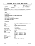
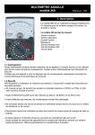
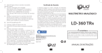
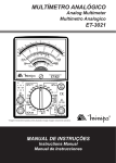
AVM360 Analog multimeter OPERATION MANUAL GEBRUIKERSHANDLEIDING MANUEL D’UTILISATEUR AVM360 Analogue Multimeter 1. Description Your AVM360 is a professional analogue multimeter. It is ideally suited for field, lab, shop, and home applications. It is capable of performing functions : DC Voltage AC Voltage Resistance Transistor Iceo test Diode test DC Current Transistor hFE test 1.1 Warning Use extreme caution in the use of this device. Improper use of this device can result in injury or death. Follow all safeguards suggested in this owner’s manual in addition to normal safety precautions in dealing with electrical circuits. Do not use this device if you are unfamiliar with electrical circuits and testing procedures. 1.2 A word about safety This multimeter is designed to ensure the safest operation possible. However, safe operation depends on you, the operator. Make sure you follow these simple safety rules : l l l l l l Never apply a voltage to the multimeter that exceeds the limits given in the specifications. Never apply more than 1000V DC or 1000V rms AC between an input jack and ground. Use extreme caution when working with voltages above 60V DC or 30 V AC rms. Always discharge filter capacitors in the power supply circuit under test before you attach test leads. Never connect to a source of voltage when you select the resistance measurement. Always turn off power and disconnect the test leads before you replace the batteries or fuse. Never operate the multimeter unless the battery cover is in place and fully closed. When carrying out measurements on television or switching power circuits, always remember that there may be high amplitude voltages pulses at test points which can damage the meter. 1.3 Maintenance AVM360 1 GB Your AVM360 is an example of superior design and craftsmanship. The following suggestions will help you care for the multimeter so you can enjoy it for years : l l l l l l l l l Keep the multimeter dry. If it gets wet, wipe it dry immediately. Use and store the multimeter only in normal temperature environments. Temperature extremes can shorten the life of electronic devices or damage batteries. Handle the multimeter gently and carefully. Dropping it can damage the circuit boards and case and can cause the multimeter to work improperly. Use only fresh batteries of the required size and type. Always remove old or weak batteries. If you do not plan to use the multimeter for a month or more, remove the batteries. This protects the multimeter from possible leakage. Disconnect the test probes before opening the multimeter. Replace blown fuse only with same size and type : F 1.5A / 250V If any faults or abnormalities are observed, do not use this device and let it check by authorised personnel. Never use the meter unless the back cover is in place and fastened fully. To clean the meter, use a damp cloth and mild detergent only, do not use abrasives or solvents. 2. Description of the meter AVM360 2 GB Indicator zero corrector ô Range selector switch knob í Measuring terminal + ÷ Measuring terminal - COM (common) û OUTPUT (series condenser) terminal ø 0 Ω adjusting knob ù Panel î Indicator Pointer ü Rear case bolt ê Rear case 3. Reference table for reading AVM360 3 GB Test Range Position DC 0.1V 0.5V 2.5V 10V 50V 250V 1000V AC 10V 50V 250V 1000V DC 50 µA 2.5 mA 25 mA 0.25 A x1 x 10 x 100 x1K x 10 K AC 10 V 50 V 250 V B B B B B B B C B B B B B B B A A A A A G G G Iceo x1 x 10 E E hFE x 10 x 1K D E F E F E F E F DC Volt AC Volt DC Current Resistance Decibel x 100 Diode x 10 x1 AVM360 4 Scale to read 10 50 250 10 50 250 10 10 50 250 10 50 250 250 250 Multiplier x 0.01 x 0.01 x 0.01 x1 x1 x1 x 100 x1 x1 x1 x 100 x1 x 0.01 x 0.1 x 0.001 x1 x 10 x 100 x 1000 x 10000 x1 x 1 + 14 dB x 1 + 28 dB x1 (for big TR) x1 (for small TR) x1 µA x 10 x1 µA x 100 x1 mA x 1 x1 mA x 10 x1 GB 4. Operating instructions 4.1 Ω test 1. Plug the test leads into COM and + sockets. 2. Place the range selector to a prescribed range position. 3. Short the test leads and turn 0Ω ADJ to set the pointer to zero position. 4. Make sure that there is no voltage across the circuit to be tested. 5. Connect the test leads to the tested resistor and read the scale in accordance with the reference table. 4.2 DCV test 1. Plug the red test lead into the + socket and the black one into the - COM. 2. Set the range selector to a selected DCV range position. 3. Connect the red test lead to the positive polarity of the circuit tested and the black one to the negative. 4. Read the DCV.A scale referring the reference table. 4.3 ACV test 1. Plug the red test lead into the + socket and the black into the - COM socket. 2. Set the range selector to a chosen ACV range position. 3. Connect the test leads to the circuit being tested regardless of the polarities. 4. Read ACV scale with the reference table. 4.4 DCA test 1. Place the red test lead into the + socket and the black in the - COM. 2. Set the range selector at a selected DCA range position. 3. Connect the red test lead to the positive polarity of the circuit tested and the black into the negative. 4. Read the DCV.A scale converted with the reference table. 4.5 ACV test on output terminal 1. Plug the red test lead into the OUTPUT socket and the black one into the COM. 2. Set the range selector at the selected range position. Connect the test leads to the circuit to be tested and read the scale in the same manner as ACV test. Such a measurement is made to block the DC voltage which is present in the same circuit and must be cut out so that AC voltage can be read alone. 4.6 Iceo transistor test AVM360 5 GB 1. Plug the test leads into + and - COM sockets. 2. Set the range selector to x10 (15mA) for small size transistor, or to x1 (150mA) for big size transistor. 3. Adjust 0Ω ADJ to set the pointer to zero position of the Ω scale. 4. Connect the transistor with the tester : For NPN transistor, the "N" terminal of the tester is connected with the COLLECTOR (C) of the transistor and the "P" terminal with the EMITTER (E) of the transistor. For PNP transistor, reverse the NPN transistor connection. 5. Read Iceo range. If the pointer is within the LEAK zone or the pointer moves up near the full scale, the tested transistor is not good. Otherwise it is a good transistor. 4.7 hFE (DC amplification) transistor test 1. Set the range selector to x 10. 2. Adjust 0Ω ADJ to adjust the pointer to zero position. 3. hFE (DC amplification) test. For NPN transistor For PNP transistor 4. Read the hFE scale. The value of the reading is Ic / Ib, which is the DC amplification degree of the tested transistor. AVM360 6 GB 4.8 Diode test 1. Set the range selector at selected range position : x 1K for 0 - 150 µA test, x 100 for 0 - 1.5 mA test, x 10 for 0 - 15 mA test, x 1 for 0 - 150 mA test. 2. Connect the diode to the tester. For IF (forward current) test, connect the "N" terminal of the tester to the positive polarity of the diode and the "P" terminal to the negative polarity of the diode. For IR (reverse current) test, reverse the connection. 3. Read IF or IR one the LI scale provided. 4. Read the linear (forward) voltage of the diode on the LV scale while testing I F or IR. 5. Specifications 5.1 DC Voltage Ranges : 0.1 - 0.5 - 2.5 - 10 - 50 - 250 - 1000 V Accuracy at FSD : 3 Sensitivity : 20 kΩ / V Extension : 25 kV (with HV probe extra) 5.2 AC Voltage Ranges : 10 - 50 - 250 - 1000 V Accuracy at FSD : 4 Sensitivity : 9 kΩ / V Decibelmeter : -10 to +22 dB 0 dB = 1mW / 600 Ω 5.3 DC Current Ranges : 50 µA (at 0.1 VDC position) - 2.5 mA - 25 mA - 0.25 A Accuracy at FSD : 3 Volt Drop : 250 mV AVM360 7 GB 5.4 Resistance Ranges : x 1 - 0.2 Ω up to 2 kΩ, midscale, at 20 Ω x 10 - 2 Ω up to 20 kΩ, midscale, at 200 Ω x 100 - 20 Ω up to 200 kΩ, midscale, at 2 kΩ x 1k - 200 Ω up to 2 MΩ, midscale, at 20 kΩ x 10k - 2 kΩ up to 20 MΩ, midscale, at 200 kΩ Accuracy at FSD : 3 5.5 General Iceo 150 µA - 1.5 mA - 15 mA - 150 mA hFE 0 -1000 (with extra connector) Size : 148 x 100 x 35 mm Weight : approx. 280g 6. Accessories Test leads Battery (9V) Operating manual 7. Battery and fuse replacement Remove screw on the back cover and open the case. Replace the exhausted battery with a new one. Fuse rarely needs replacement and blows usually as a result of the operator's error. Open the case as mentioned above and replace the blown fuse with ratings specified : F 1.5 A / 250 V Remark : Before attempting to open the case, be sure that the test leads have been disconnected from measurement circuit to avoid electric shock. AVM360 8 GB