1
INSTALLATION AND
OPERATION MANUAL
Optimux-108
Four-Channel E1 and Ethernet Multiplexer
Version 6.1
The Access Company
Optimux-108
Four-Channel E1 and Ethernet Multiplexer
Version 6.1
Installation and Operation Manual
Notice
This manual contains information that is proprietary to RAD Data Communications Ltd. ("RAD").
No part of this publication may be reproduced in any form whatsoever without prior written
approval by RAD Data Communications.
Right, title and interest, all information, copyrights, patents, know-how, trade secrets and other
intellectual property or other proprietary rights relating to this manual and to the Optimux-108
and any software components contained therein are proprietary products of RAD protected
under international copyright law and shall be and remain solely with RAD.
The Optimux-108 product name is owned by RAD. No right, license, or interest to such
trademark is granted hereunder, and you agree that no such right, license, or interest shall be
asserted by you with respect to such trademark. The RAD name, logo, logotype, and the terms
EtherAccess, TDMoIP and TDMoIP Driven, and the product names Optimux and IPmux, are
registered trademarks of RAD Data Communications Ltd. All other trademarks are the property of
their respective holders.
You shall not copy, reverse compile or reverse assemble all or any portion of the Manual or the
Optimux-108. You are prohibited from, and shall not, directly or indirectly, develop, market,
distribute, license, or sell any product that supports substantially similar functionality as the
Optimux-108, based on or derived in any way from the Optimux-108. Your undertaking in this
paragraph shall survive the termination of this Agreement.
This Agreement is effective upon your opening of the Optimux-108 package and shall continue
until terminated. RAD may terminate this Agreement upon the breach by you of any term hereof.
Upon such termination by RAD, you agree to return to RAD the Optimux-108 and all copies and
portions thereof.
For further information contact RAD at the address below or contact your local distributor.
International Headquarters
RAD Data Communications Ltd.
North America Headquarters
RAD Data Communications Inc.
24 Raoul Wallenberg Street
Tel Aviv 69719, Israel
Tel: 972-3-6458181
Fax: 972-3-6498250, 6474436
E-mail: [email protected]
900 Corporate Drive
Mahwah, NJ 07430, USA
Tel: (201) 5291100, Toll free: 1-800-4447234
Fax: (201) 5295777
E-mail: [email protected]
© 1997–2009 RAD Data Communications Ltd.
Publication No. 324-200-03/09
Limited Warranty
RAD warrants to DISTRIBUTOR that the hardware in the Optimux-108 to be delivered hereunder
shall be free of defects in material and workmanship under normal use and service for a period
of twelve (12) months following the date of shipment to DISTRIBUTOR.
If, during the warranty period, any component part of the equipment becomes defective by
reason of material or workmanship, and DISTRIBUTOR immediately notifies RAD of such defect,
RAD shall have the option to choose the appropriate corrective action: a) supply a replacement
part, or b) request return of equipment to its plant for repair, or c) perform necessary repair at
the equipment's location. In the event that RAD requests the return of equipment, each party
shall pay one-way shipping costs.
RAD shall be released from all obligations under its warranty in the event that the equipment has
been subjected to misuse, neglect, accident or improper installation, or if repairs or
modifications were made by persons other than RAD's own authorized service personnel, unless
such repairs by others were made with the written consent of RAD.
The above warranty is in lieu of all other warranties, expressed or implied. There are no
warranties which extend beyond the face hereof, including, but not limited to, warranties of
merchantability and fitness for a particular purpose, and in no event shall RAD be liable for
consequential damages.
RAD shall not be liable to any person for any special or indirect damages, including, but not
limited to, lost profits from any cause whatsoever arising from or in any way connected with the
manufacture, sale, handling, repair, maintenance or use of the Optimux-108, and in no event
shall RAD's liability exceed the purchase price of the Optimux-108.
DISTRIBUTOR shall be responsible to its customers for any and all warranties which it makes
relating to Optimux-108 and for ensuring that replacements and other adjustments required in
connection with the said warranties are satisfactory.
Software components in the Optimux-108 are provided "as is" and without warranty of any kind.
RAD disclaims all warranties including the implied warranties of merchantability and fitness for a
particular purpose. RAD shall not be liable for any loss of use, interruption of business or
indirect, special, incidental or consequential damages of any kind. In spite of the above RAD
shall do its best to provide error-free software products and shall offer free Software updates
during the warranty period under this Agreement.
RAD's cumulative liability to you or any other party for any loss or damages resulting from any
claims, demands, or actions arising out of or relating to this Agreement and the Optimux-108
shall not exceed the sum paid to RAD for the purchase of the Optimux-108. In no event shall
RAD be liable for any indirect, incidental, consequential, special, or exemplary damages or lost
profits, even if RAD has been advised of the possibility of such damages.
This Agreement shall be construed and governed in accordance with the laws of the State of
Israel.
Product Disposal
To facilitate the reuse, recycling and other forms of recovery of waste
equipment in protecting the environment, the owner of this RAD product is
required to refrain from disposing of this product as unsorted municipal
waste at the end of its life cycle. Upon termination of the unit’s use,
customers should provide for its collection for reuse, recycling or other form
of environmentally conscientious disposal.
General Safety Instructions
The following instructions serve as a general guide for the safe installation and operation of
telecommunications products. Additional instructions, if applicable, are included inside the
manual.
Safety Symbols
This symbol may appear on the equipment or in the text. It indicates potential
safety hazards regarding product operation or maintenance to operator or service
personnel.
Warning
Danger of electric shock! Avoid any contact with the marked surface while the
product is energized or connected to outdoor telecommunication lines.
Protective ground: the marked lug or terminal should be connected to the building
protective ground bus.
Warning
Some products may be equipped with a laser diode. In such cases, a label with the
laser class and other warnings as applicable will be attached near the optical
transmitter. The laser warning symbol may be also attached.
Please observe the following precautions:
•
Before turning on the equipment, make sure that the fiber optic cable is intact
and is connected to the transmitter.
•
Do not attempt to adjust the laser drive current.
•
Do not use broken or unterminated fiber-optic cables/connectors or look
straight at the laser beam.
•
The use of optical devices with the equipment will increase eye hazard.
•
Use of controls, adjustments or performing procedures other than those
specified herein, may result in hazardous radiation exposure.
ATTENTION: The laser beam may be invisible!
In some cases, the users may insert their own SFP laser transceivers into the product. Users are
alerted that RAD cannot be held responsible for any damage that may result if non-compliant
transceivers are used. In particular, users are warned to use only agency approved products that
comply with the local laser safety regulations for Class 1 laser products.
Always observe standard safety precautions during installation, operation and maintenance of
this product. Only qualified and authorized service personnel should carry out adjustment,
maintenance or repairs to this product. No installation, adjustment, maintenance or repairs
should be performed by either the operator or the user.
Handling Energized Products
General Safety Practices
Do not touch or tamper with the power supply when the power cord is connected. Line voltages
may be present inside certain products even when the power switch (if installed) is in the OFF
position or a fuse is blown. For DC-powered products, although the voltages levels are usually
not hazardous, energy hazards may still exist.
Before working on equipment connected to power lines or telecommunication lines, remove
jewelry or any other metallic object that may come into contact with energized parts.
Unless otherwise specified, all products are intended to be grounded during normal use.
Grounding is provided by connecting the mains plug to a wall socket with a protective ground
terminal. If a ground lug is provided on the product, it should be connected to the protective
ground at all times, by a wire with a diameter of 18 AWG or wider. Rack-mounted equipment
should be mounted only in grounded racks and cabinets.
Always make the ground connection first and disconnect it last. Do not connect
telecommunication cables to ungrounded equipment. Make sure that all other cables are
disconnected before disconnecting the ground.
Some products may have panels secured by thumbscrews with a slotted head. These panels may
cover hazardous circuits or parts, such as power supplies. These thumbscrews should therefore
always be tightened securely with a screwdriver after both initial installation and subsequent
access to the panels.
Connecting AC Mains
Make sure that the electrical installation complies with local codes.
Always connect the AC plug to a wall socket with a protective ground.
The maximum permissible current capability of the branch distribution circuit that supplies power
to the product is 16A (20A for USA and Canada). The circuit breaker in the building installation
should have high breaking capacity and must operate at short-circuit current exceeding 35A (40A
for USA and Canada).
Always connect the power cord first to the equipment and then to the wall socket. If a power
switch is provided in the equipment, set it to the OFF position. If the power cord cannot be
readily disconnected in case of emergency, make sure that a readily accessible circuit breaker or
emergency switch is installed in the building installation.
In cases when the power distribution system is IT type, the switch must disconnect both poles
simultaneously.
Connecting DC Power
Unless otherwise specified in the manual, the DC input to the equipment is floating in reference
to the ground. Any single pole can be externally grounded.
Due to the high current capability of DC power systems, care should be taken when connecting
the DC supply to avoid short-circuits and fire hazards.
Make sure that the DC power supply is electrically isolated from any AC source and that the
installation complies with the local codes.
The maximum permissible current capability of the branch distribution circuit that supplies power
to the product is 16A (20A for USA and Canada). The circuit breaker in the building installation
should have high breaking capacity and must operate at short-circuit current exceeding 35A (40A
for USA and Canada).
Before connecting the DC supply wires, ensure that power is removed from the DC circuit. Locate
the circuit breaker of the panel board that services the equipment and switch it to the OFF
position. When connecting the DC supply wires, first connect the ground wire to the
corresponding terminal, then the positive pole and last the negative pole. Switch the circuit
breaker back to the ON position.
A readily accessible disconnect device that is suitably rated and approved should be incorporated
in the building installation.
If the DC power supply is floating, the switch must disconnect both poles simultaneously.
Connecting Data and Telecommunications Cables
Data and telecommunication interfaces are classified according to their safety status.
The following table lists the status of several standard interfaces. If the status of a given port
differs from the standard one, a notice will be given in the manual.
Ports
Safety Status
V.11, V.28, V.35, V.36, RS-530, X.21,
10 BaseT, 100 BaseT, Unbalanced E1,
E2, E3, STM, DS-2, DS-3, S-Interface
ISDN, Analog voice E&M
SELV
xDSL (without feeding voltage),
Balanced E1, T1, Sub E1/T1
TNV-1 Telecommunication Network Voltage-1:
Ports whose normal operating voltage is within the
limits of SELV, on which overvoltages from
telecommunications networks are possible.
FXS (Foreign Exchange Subscriber)
TNV-2 Telecommunication Network Voltage-2:
Ports whose normal operating voltage exceeds the
limits of SELV (usually up to 120 VDC or telephone
ringing voltages), on which overvoltages from
telecommunication networks are not possible. These
ports are not permitted to be directly connected to
external telephone and data lines.
FXO (Foreign Exchange Office), xDSL
(with feeding voltage), U-Interface
ISDN
TNV-3 Telecommunication Network Voltage-3:
Ports whose normal operating voltage exceeds the
limits of SELV (usually up to 120 VDC or telephone
ringing voltages), on which overvoltages from
telecommunication networks are possible.
Safety Extra Low Voltage:
Ports which do not present a safety hazard. Usually
up to 30 VAC or 60 VDC.
Always connect a given port to a port of the same safety status. If in doubt, seek the assistance
of a qualified safety engineer.
Always make sure that the equipment is grounded before connecting telecommunication cables.
Do not disconnect the ground connection before disconnecting all telecommunications cables.
Some SELV and non-SELV circuits use the same connectors. Use caution when connecting cables.
Extra caution should be exercised during thunderstorms.
When using shielded or coaxial cables, verify that there is a good ground connection at both
ends. The grounding and bonding of the ground connections should comply with the local codes.
The telecommunication wiring in the building may be damaged or present a fire hazard in case of
contact between exposed external wires and the AC power lines. In order to reduce the risk,
there are restrictions on the diameter of wires in the telecom cables, between the equipment
and the mating connectors.
Caution
To reduce the risk of fire, use only No. 26 AWG or larger telecommunication line
cords.
Attention
Pour réduire les risques s’incendie, utiliser seulement des conducteurs de
télécommunications 26 AWG ou de section supérieure.
Some ports are suitable for connection to intra-building or non-exposed wiring or cabling only. In
such cases, a notice will be given in the installation instructions.
Do not attempt to tamper with any carrier-provided equipment or connection hardware.
Electromagnetic Compatibility (EMC)
The equipment is designed and approved to comply with the electromagnetic regulations of
major regulatory bodies. The following instructions may enhance the performance of the
equipment and will provide better protection against excessive emission and better immunity
against disturbances.
A good ground connection is essential. When installing the equipment in a rack, make sure to
remove all traces of paint from the mounting points. Use suitable lock-washers and torque. If an
external grounding lug is provided, connect it to the ground bus using braided wire as short as
possible.
The equipment is designed to comply with EMC requirements when connecting it with unshielded
twisted pair (UTP) cables. However, the use of shielded wires is always recommended, especially
for high-rate data. In some cases, when unshielded wires are used, ferrite cores should be
installed on certain cables. In such cases, special instructions are provided in the manual.
Disconnect all wires which are not in permanent use, such as cables used for one-time
configuration.
The compliance of the equipment with the regulations for conducted emission on the data lines
is dependent on the cable quality. The emission is tested for UTP with 80 dB longitudinal
conversion loss (LCL).
Unless otherwise specified or described in the manual, TNV-1 and TNV-3 ports provide secondary
protection against surges on the data lines. Primary protectors should be provided in the building
installation.
The equipment is designed to provide adequate protection against electro-static discharge (ESD).
However, it is good working practice to use caution when connecting cables terminated with
plastic connectors (without a grounded metal hood, such as flat cables) to sensitive data lines.
Before connecting such cables, discharge yourself by touching ground or wear an ESD preventive
wrist strap.
FCC-15 User Information
This equipment has been tested and found to comply with the limits of the Class A digital device,
pursuant to Part 15 of the FCC rules. These limits are designed to provide reasonable protection
against harmful interference when the equipment is operated in a commercial environment. This
equipment generates, uses and can radiate radio frequency energy and, if not installed and used
in accordance with the Installation and Operation manual, may cause harmful interference to the
radio communications. Operation of this equipment in a residential area is likely to cause harmful
interference in which case the user will be required to correct the interference at his own
expense.
Canadian Emission Requirements
This Class A digital apparatus meets all the requirements of the Canadian Interference-Causing
Equipment Regulation.
Cet appareil numérique de la classe A respecte toutes les exigences du Règlement sur le matériel
brouilleur du Canada.
Warning per EN 55022 (CISPR-22)
Warning
Avertissement
Achtung
This is a class A product. In a domestic environment, this product may cause radio
interference, in which case the user will be required to take adequate measures.
Cet appareil est un appareil de Classe A. Dans un environnement résidentiel, cet
appareil peut provoquer des brouillages radioélectriques. Dans ces cas, il peut être
demandé à l’utilisateur de prendre les mesures appropriées.
Das vorliegende Gerät fällt unter die Funkstörgrenzwertklasse A. In Wohngebieten
können beim Betrieb dieses Gerätes Rundfunkströrungen auftreten, für deren
Behebung der Benutzer verantwortlich ist.
Français
Mise au rebut du produit
Afin de faciliter la réutilisation, le recyclage ainsi que d'autres formes de
récupération d'équipement mis au rebut dans le cadre de la protection de
l'environnement, il est demandé au propriétaire de ce produit RAD de ne pas
mettre ce dernier au rebut en tant que déchet municipal non trié, une fois
que le produit est arrivé en fin de cycle de vie. Le client devrait proposer des
solutions de réutilisation, de recyclage ou toute autre forme de mise au rebut
de cette unité dans un esprit de protection de l'environnement, lorsqu'il aura
fini de l'utiliser.
Instructions générales de sécurité
Les instructions suivantes servent de guide général d'installation et d'opération sécurisées des
produits de télécommunications. Des instructions supplémentaires sont éventuellement
indiquées dans le manuel.
Symboles de sécurité
Ce symbole peut apparaitre sur l'équipement ou dans le texte. Il indique des risques
potentiels de sécurité pour l'opérateur ou le personnel de service, quant à
l'opération du produit ou à sa maintenance.
Avertissement
Danger de choc électrique ! Evitez tout contact avec la surface marquée tant que le
produit est sous tension ou connecté à des lignes externes de télécommunications.
Mise à la terre de protection : la cosse ou la borne marquée devrait être connectée
à la prise de terre de protection du bâtiment.
•
Avant la mise en marche de l'équipement, assurez-vous que le câble de fibre
optique est intact et qu'il est connecté au transmetteur.
•
Ne tentez pas d'ajuster le courant de la commande laser.
•
N'utilisez pas des câbles ou connecteurs de fibre optique cassés ou sans
terminaison et n'observez pas directement un rayon laser.
•
L'usage de périphériques optiques avec l'équipement augmentera le risque pour
les yeux.
•
L'usage de contrôles, ajustages ou procédures autres que celles spécifiées ici
pourrait résulter en une dangereuse exposition aux radiations.
ATTENTION : Le rayon laser peut être invisible !
Les utilisateurs pourront, dans certains cas, insérer leurs propres émetteurs-récepteurs Laser SFP
dans le produit. Les utilisateurs sont avertis que RAD ne pourra pas être tenue responsable de
tout dommage pouvant résulter de l'utilisation d'émetteurs-récepteurs non conformes. Plus
particulièrement, les utilisateurs sont avertis de n'utiliser que des produits approuvés par
l'agence et conformes à la réglementation locale de sécurité laser pour les produits laser de
classe 1.
Respectez toujours les précautions standards de sécurité durant l'installation, l'opération et la
maintenance de ce produit. Seul le personnel de service qualifié et autorisé devrait effectuer
l'ajustage, la maintenance ou les réparations de ce produit. Aucune opération d'installation,
d'ajustage, de maintenance ou de réparation ne devrait être effectuée par l'opérateur ou
l'utilisateur.
Manipuler des produits sous tension
Règles générales de sécurité
Ne pas toucher ou altérer l'alimentation en courant lorsque le câble d'alimentation est branché.
Des tensions de lignes peuvent être présentes dans certains produits, même lorsque le
commutateur (s'il est installé) est en position OFF ou si le fusible est rompu. Pour les produits
alimentés par CC, les niveaux de tension ne sont généralement pas dangereux mais des risques
de courant peuvent toujours exister.
Avant de travailler sur un équipement connecté aux lignes de tension ou de télécommunications,
retirez vos bijoux ou tout autre objet métallique pouvant venir en contact avec les pièces sous
tension.
Sauf s'il en est autrement indiqué, tous les produits sont destinés à être mis à la terre durant
l'usage normal. La mise à la terre est fournie par la connexion de la fiche principale à une prise
murale équipée d'une borne protectrice de mise à la terre. Si une cosse de mise à la terre est
fournie avec le produit, elle devrait être connectée à tout moment à une mise à la terre de
protection par un conducteur de diamètre 18 AWG ou plus. L'équipement monté en châssis ne
devrait être monté que sur des châssis et dans des armoires mises à la terre.
Branchez toujours la mise à la terre en premier et débranchez-la en dernier. Ne branchez pas des
câbles de télécommunications à un équipement qui n'est pas mis à la terre. Assurez-vous que
tous les autres câbles sont débranchés avant de déconnecter la mise à la terre.
Français
Certains produits peuvent être équipés d'une diode laser. Dans de tels cas, une
étiquette indiquant la classe laser ainsi que d'autres avertissements, le cas échéant,
sera jointe près du transmetteur optique. Le symbole d'avertissement laser peut
aussi être joint.
Avertissement
Veuillez observer les précautions suivantes :
Français
Connexion au courant du secteur
Assurez-vous que l'installation électrique est conforme à la réglementation locale.
Branchez toujours la fiche de secteur à une prise murale équipée d'une borne protectrice de mise
à la terre.
La capacité maximale permissible en courant du circuit de distribution de la connexion alimentant
le produit est de 16A (20A aux Etats-Unis et Canada). Le coupe-circuit dans l'installation du
bâtiment devrait avoir une capacité élevée de rupture et devrait fonctionner sur courant de
court-circuit dépassant 35A (40A aux Etats-Unis et Canada).
Branchez toujours le câble d'alimentation en premier à l'équipement puis à la prise murale. Si un
commutateur est fourni avec l'équipement, fixez-le en position OFF. Si le câble d'alimentation ne
peut pas être facilement débranché en cas d'urgence, assurez-vous qu'un coupe-circuit ou un
disjoncteur d'urgence facilement accessible est installé dans l'installation du bâtiment.
Le disjoncteur devrait déconnecter simultanément les deux pôles si le système de distribution de
courant est de type IT.
Connexion d'alimentation CC
Sauf s'il en est autrement spécifié dans le manuel, l'entrée CC de l'équipement est flottante par
rapport à la mise à la terre. Tout pôle doit être mis à la terre en externe.
A cause de la capacité de courant des systèmes à alimentation CC, des précautions devraient
être prises lors de la connexion de l'alimentation CC pour éviter des courts-circuits et des risques
d'incendie.
Assurez-vous que l'alimentation CC est isolée de toute source de courant CA (secteur) et que
l'installation est conforme à la réglementation locale.
La capacité maximale permissible en courant du circuit de distribution de la connexion alimentant
le produit est de 16A (20A aux Etats-Unis et Canada). Le coupe-circuit dans l'installation du
bâtiment devrait avoir une capacité élevée de rupture et devrait fonctionner sur courant de
court-circuit dépassant 35A (40A aux Etats-Unis et Canada).
Avant la connexion des câbles d'alimentation en courant CC, assurez-vous que le circuit CC n'est
pas sous tension. Localisez le coupe-circuit dans le tableau desservant l'équipement et fixez-le
en position OFF. Lors de la connexion de câbles d'alimentation CC, connectez d'abord le
conducteur de mise à la terre à la borne correspondante, puis le pôle positif et en dernier, le
pôle négatif. Remettez le coupe-circuit en position ON.
Un disjoncteur facilement accessible, adapté et approuvé devrait être intégré à l'installation du
bâtiment.
Le disjoncteur devrait déconnecter simultanément les deux pôles si l'alimentation en courant CC
est flottante.
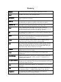
Glossary
Address
A coded representation of the origin or destination of data.
Agent
In SNMP, this refers to the managed system.
Attenuation
Signal power loss through equipment, lines or other transmission
devices. Measured in decibels.
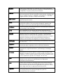
Balanced
A transmission line in which voltages on the two conductors are equal
in magnitude, but opposite in polarity, with respect to ground.
Balanced Line
A circuit in which neither side of the line is grounded. This minimizes
crosstalk or noise pickup between pairs in the same cable.
Baud
Unit of signaling speed equivalent to the number of discrete
conditions or events per second. If each signal event represents only
one bit condition, baud rate equals bps (bits per second).
Bit
The smallest unit of information in a binary system. Represents either
a one or zero (“1” or “0”).
Buffer
A storage device. Commonly used to compensate for differences in
data rates or event timing when transmitting from one device to
another. Also used to remove jitter.
Carrier
A continuous signal at a fixed frequency that is capable of being
modulated with a second (information carrying) signal.
Cell
The 53-byte basic information unit within an ATM network. The user
traffic is segmented into cells at the source and reassembled at the
destination. An ATM cell consists of a 5-byte ATM header and a 48byte ATM payload, which contains the user data.
Channel
A path for electrical transmission between two or more points. Also
called a link, line, circuit or facility.
Clock
A term for the source(s) of timing signals used in synchronous
transmission.
Control Signals
Signals passing between one part of a communications system and
another (such as RTS, DTR, or DCD), as part of a mechanism for
controlling the system.
CTS (Clear To Send)
A modem interface control signal from the data communications
equipment (DCE) indicating to the data terminal equipment (DTE) that
it may begin data transmission.
Data
Information represented in digital form, including voice, text, facsimile
and video.
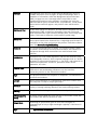
dBm
A measure of power in communications: the decibel in reference to
one milliwatt (0 dBm = 1 milliwatt and -30 dBm = .001 milliwatt).
Diagnostics
The detection and isolation of a malfunction or mistake in a
communications device, network or system.
Equalizer
A device that compensates for distortion due to signal attenuation
and propagation time with respect to frequency. It reduces the effects
of amplitude, frequency and/or phase distortion.
Ethernet
A local area network (LAN) technology which has extended into the
wide area networks. Ethernet operates at many speeds, including data
rates of 10 Mbps (Ethernet), 100 Mbps (Fast Ethernet), 1,000 Mbps
(Gigabit Ethernet), 10 Gbps, 40 Gbps, and 100 Gbps.
Flow Control
A congestion control mechanism that results in an ATM system
implementing flow control.
Frame
A logical grouping of information sent as a link-layer unit over a
transmission medium. The terms packet, datagram, segment, and
message are also used to describe logical information groupings.
Full Duplex
A circuit or device permitting transmission in two directions (sending
and receiving) at the same time.
G.703
An ITU standard for the physical and electrical characteristics of
various digital interfaces, including those at 64 kbps and 2.048 Mbps.
Gateway
Gateways are points of entrance and exit from a communications
network. Viewed as a physical entity, a gateway is that node that
translates between two otherwise incompatible networks or network
segments. Gateways perform code and protocol conversion to
facilitate traffic between data highways of differing architecture.
Half Duplex
A circuit or device capable of transmitting in two directions, but not at
the same time.
Impedance
The combined effect of resistance, inductance and capacitance on a
transmitted signal. Impedance varies at different frequencies.
Interface
A shared boundary, defined by common physical interconnection
characteristics, signal characteristics, and meanings of exchanged
signals.
IP Address
Also known as an Internet address. A unique string of numbers that
identifies a computer or device on a TCP/IP network. The format of an
IP address is a 32-bit numeric address written as four numbers from 0
to 255, separated by periods (for example, 1.0.255.123).
Jitter
The deviation of a transmission signal in time or phase. It can
introduce errors and loss of synchronization in high speed
synchronous communications.
Laser
A device that transmits an extremely narrow and coherent beam of
electromagnetic energy in the visible light spectrum. Used as a light
source for fiber optic transmission (generally more expensive, shorter
lived, single mode only, for greater distances than LED).
Loopback
A type of diagnostic test in which the transmitted signal is returned to
the sending device after passing through all or part of a
communications link or network.
Manager
An application that receives Simple Network Management Protocol
(SNMP) information from an agent. An agent and manager share a
database of information, called the Management Information Base
(MIB). An agent can use a message called a traps-PDU to send
unsolicited information to the manager. A manager that uses the
RADview MIB can query the RAD device, set parameters, sound alarms
when certain conditions appear, and perform other administrative
tasks.
Multimode Fiber
A fiber with a large core diameter; 50-200 microns compared with the
wavelength of light. It therefore propagates more than one mode.
With multimode fiber, light traverses multiple paths, some longer than
others. This leads to dispersion, which reduces optical range.
Multiplexer
At one end of a communications link, a device that combines several
lower speed transmission channels into a single high speed channel. A
multiplexer at the other end reverses the process. Sometimes called a
mux. See Bit Interleaving/Multiplexing.
Network
(1) An interconnected group of nodes. (2) A series of points, nodes,
or stations connected by communications channels; the collection of
equipment through which connections are made between data
stations.
parameters
Parameters are often called arguments, and the two words are used
interchangeably. However, some computer languages such as C define
argument to mean actual parameter (i.e., the value), and parameter to
mean formal parameter. In RAD CLI, parameter means formal
parameter, not value.
Physical Layer
Layer 1 of the OSI model. The layer concerned with electrical,
mechanical, and handshaking procedures over the interface
connecting a device to the transmission medium.
Port
The physical interface to a computer or multiplexer, for connection of
terminals and modems.
prompt
One or more characters in a command line interface to indicate that
the computer is ready to accept typed input.
Protocol
A formal set of conventions governing the formatting and relative
timing of message exchange between two communicating systems.
Routing
The process of selecting the most efficient circuit path for a message.
RTS (Request To
Send)
A modem control signal sent from the DTE to the modem, which tells
the modem that the DTE has data to send.
Single Mode
Describing an optical wave-guide or fiber that is designed to
propagate light of only a single wavelength (typically 5-10 microns in
diameter).
Sync
See Synchronous Transmission.
Telnet
The virtual terminal protocol in the Internet suite of protocols. It lets
users on one host access another host and work as terminal users of
that remote host. Instead of dialing into the computer, the user
connects to it over the Internet using Telnet. When issuing a Telnet
session, it connects to the Telnet host and logs in. The connection
enables the user to work with the remote machine as though a
terminal was connected to it.
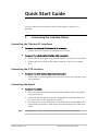
Quick Start Guide
If you are familiar with the Optimux-108, use this guide to prepare it for
operation.
1.
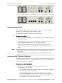
Connecting the Interface Cables
Connecting the Tributary E1 Interfaces
³
To connect the balanced E1 interface (RJ-45 connector)
•
³
Connect the RJ-45 connector of the cable to the E1 port.
To connect the unbalanced E1 interface (BNC connectors)
1. Connect the transmit cable to the coaxial connector of the E1 port marked IN.
2. Connect the receive cable to the coaxial connector of the E1 port marked
OUT.
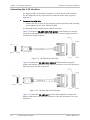
Connecting the V.35 Interface
³
To connect the V.35 interface (Smart serial connector)
•
Connect the V.35 cable supplied with the product to the V.35 interface smart
serial connector.
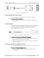
Connecting the Uplink
³
To connect the uplink:
1. Clean the optical connectors using an approved solvent, and dry thoroughly
using optical tissue.
2. Connect to the two optical connectors designated TX (transmit output) and
RX (receive input) of the appropriate interface.
3. Pay attention to correct connection of the transmit and receive cables to the
corresponding connectors. Avoid sharp bends and twisting of the fiber-optic
cables.
Note
For WDM option, only one fiber optic cable per link should be connected.
Optimux-108 Ver. 6.1
Connecting the Interface Cables
1
Quick Start Guide
Installation and Operation Manual
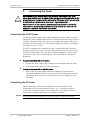
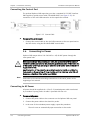
2.
Warning
Connecting the Power
Before powering this unit and before connecting or disconnecting any other
cable, the protective earth terminals of this instrument must be connected to the
protective ground conductor of the mains (AC or DC) power cord. If you are using
an extension cord (power cable) make sure it is grounded as well.
Any interruption of the protective grounding conductor (inside or outside the
instrument) or disconnecting the protective earth terminal can make this unit
dangerous. Intentional interruption is prohibited.
Connecting the AC/DC Power
The Optimux-108 is supplied with a Wide Range AC/DC power supply. The widerange AC/DC power supply accepts current from both AC and DC sources. From an
AC source, the power supply can receive any voltage in the range of 100 VAC to
240 VAC. From a DC source, the -48 VDC power supply can receive any voltage in
the range of -40 to -72 VDC.
This unit is equipped with a standard AC-type 3-prong power input connector
located on the unit rear panel. This power input connector can be used for both
AC and DC voltage inputs. AC or DC power should be supplied to Optimux-108
through the 5-feet (1.5m) standard power cable terminated by a standard 3prong plug.
³
To connect Optimux-108 to AC power:
1. Connect the power cable to the connector on the Optimux-108 rear panel.
2. Connect the power cable to the electricity outlet.
³
To connect Optimux-108 to -48 VDC power:
•
Refer to the DC power supply connection supplement, located on the
Technical Documentation CD or at the back of the official printed version of
this manual. Also, refer to the safety instructions at the beginning of this
document.
Connecting the DC Power
When connecting the DC power, the PWR pin must be connected to the
ungrounded line of the central battery (either − or +). The RTN pin must be
connected to the grounded line of the central battery. The GND pin must be
connected to the protected earth of the building installation.
Caution
2
The DC installation procedure must be performed by a qualified technician.
Connecting the Power
Optimux-108 Ver. 6.1
Installation and Operation Manual
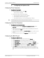
3.
Quick Start Guide
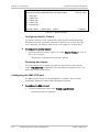
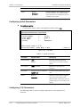
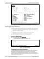
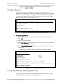
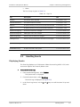
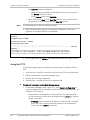
Configuring the Optimux-108
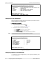
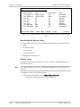
Configuring IP Host Parameters
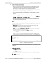
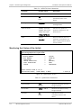
³
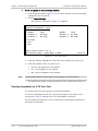
To define the IP parameters:
1. From the Management menu, select Host.
The Host menu is displayed.
2. From the Host menu, perform the following:
Note
Select IP Address to define the host IP address
Select IP Mask to define the host IP mask
Select Default Gateway to set the default gateway IP address.
The default gateway must be in the same subnet as the host.
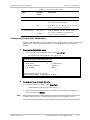
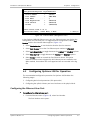
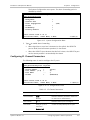
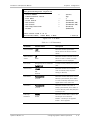
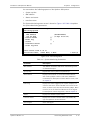
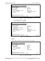
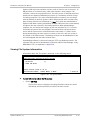
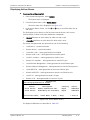
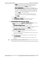
Configuring Control Port Parameters
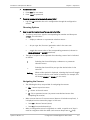
³
To configure the control port data rate:
1. From the Control Port menu (Configuration>System>Control Port), select
Baud Rate.
2. Select the terminal rate by typing the number corresponding to the desired
value, and then press <Enter>.
3. From the Control Port menu, select Security Timeout to set it to OFF or to 10
minutes.
4. From the Control Port menu, select Pop Alarm to set it to ON or to OFF.
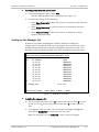
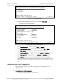
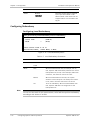
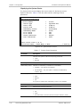
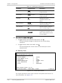
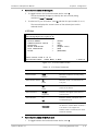
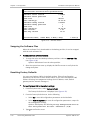
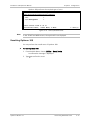
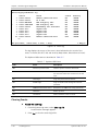
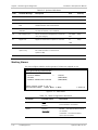
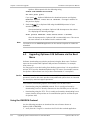
Configuring the MNG-ETH port
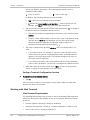
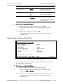
³
To configure the MNG-ETH port:
1. From the Configuration menu select Physical Layer>Ethernet.
2. Select Device Number to set the device location (local or remote).
3. Select Port Number to set the Fast Ethernet port number to ETH-MNG.
4. Select Auto Negotiation to toggle between the Enabled and Disabled options.
5. Select Flow Control to toggle between the Enabled and Disabled options.
6. Select Alarms to mask or unmask the Fast Ethernet alarms. This option
identifies whether alarms triggered by this Ethernet port are masked or not.
When masked, these alarms are not trapped and are not recorded in the log
file.
Optimux-108 Ver. 6.1
Configuring the Optimux-108
3
Quick Start Guide
4
Configuring the Optimux-108
Installation and Operation Manual
Optimux-108 Ver. 6.1
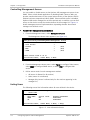
Contents
Chapter 1. Introduction
1.1
1.2
1.3
1.4
Overview.................................................................................................................... 1-1
Product Options...................................................................................................... 1-1
Applications ............................................................................................................ 1-1
Features ................................................................................................................. 1-2
Physical Description ................................................................................................... 1-3
Functional Description................................................................................................ 1-3
Printed Circuit Boards ............................................................................................. 1-3
Fiber Optic Uplink Interface ..................................................................................... 1-3
Technical Characteristics .................................................................................... 1-4
Uplink Redundancy Option ................................................................................. 1-4
E1 Tributary Interface ............................................................................................. 1-5
V.35 User Port ........................................................................................................ 1-5
Ethernet User Port .................................................................................................. 1-5
Timing .................................................................................................................... 1-5
Test and Diagnostics Capabilities ............................................................................ 1-6
Alarms and Alarm Indications .................................................................................. 1-7
Uplink and Triburaties ........................................................................................ 1-7
V.35 User Port.................................................................................................... 1-7
Response to Alarm Conditions ............................................................................ 1-7
Rear Panel Alarm Connector ............................................................................... 1-7
Events .................................................................................................................... 1-8
Management .......................................................................................................... 1-8
Power ..................................................................................................................... 1-8
Technical Specifications.............................................................................................. 1-8
Chapter 2. Installation and Setup
2.1
2.2
2.3
2.4
2.5
2.6
Site Requirements and Prerequisites .......................................................................... 2-1
Package Contents ...................................................................................................... 2-2
Required Equipment ................................................................................................... 2-2
Mounting the Unit ...................................................................................................... 2-2
Connecting the Interfaces .......................................................................................... 2-3
Connector Location................................................................................................. 2-3
Connecting the Uplink ............................................................................................. 2-4
Connecting the Tributary Interface .......................................................................... 2-5
Connecting the V.35 Interface ................................................................................. 2-5
Connecting the User Ethernet Port .......................................................................... 2-6
Alarm Connector ..................................................................................................... 2-7
Connecting the Ethernet Management Port ............................................................. 2-7
Connecting the Control Port .................................................................................... 2-7
Connecting to Power .................................................................................................. 2-8
Connecting AC Power .............................................................................................. 2-8
Connecting DC Power.............................................................................................. 2-8
Chapter 3. Operation
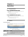
3.1
3.2
Turning On the Unit ................................................................................................... 3-1
Indicators .................................................................................................................. 3-1
Front Panel Indicators ............................................................................................. 3-1
Optimux-108 Ver. 6.1
i
Table of Contents
3.3
3.4
3.5
3.6
Installation and Operation Manual
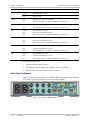
Rear Panel Indicators .............................................................................................. 3-3
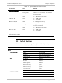
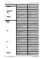
Default Settings ......................................................................................................... 3-4
Configuration and Management Alternatives .............................................................. 3-5
Working with Terminal ............................................................................................ 3-6
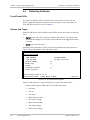
Login ................................................................................................................. 3-6
Choosing Options ............................................................................................... 3-7
Navigating the Screens ....................................................................................... 3-8
Ending a Terminal Configuration Session............................................................. 3-9
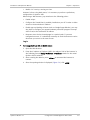
Working with Web Terminal..................................................................................... 3-9
Web Browser Requirements ............................................................................... 3-9
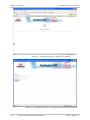
Login ............................................................................................................... 3-10
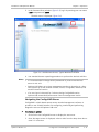
Navigating the ConfiguRAD Menus .................................................................... 3-12
Working with SNMP-based Management System ................................................... 3-13
RADview-PC/TDM and RADview-HPOV/TDM ....................................................... 3-13
Third-party SNMP-based NMS ........................................................................... 3-13
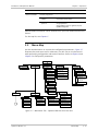
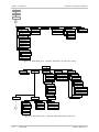
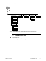
Menu Map ................................................................................................................ 3-14
Turning Off the Unit ................................................................................................. 3-16
Chapter 4. Configuration
4.1
4.2
4.3
ii
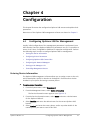
Configuring Optimux-108 for Management ................................................................. 4-1
Entering Device Information .................................................................................... 4-1
Configuring IP Host Parameters ............................................................................... 4-2
Configuring Optimux-108 Communities ................................................................... 4-2
Setting up the Manager List .................................................................................... 4-3
Controlling Management Access .............................................................................. 4-4
Listing Users ........................................................................................................... 4-4
Configuring Control Port Parameters ....................................................................... 4-5
Configuring Security Timeout .............................................................................. 4-6
Displaying New Alarms ....................................................................................... 4-6
Configuring the MNG-ETH port ................................................................................ 4-6
Configuring Optimux-108 for Operation ..................................................................... 4-7
Configuring the Ethernet User Port ......................................................................... 4-7
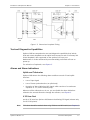
Configuring the Fault Propagation ........................................................................... 4-8
Configuring E1 Channel Parameters ......................................................................... 4-9
Configuring Uplink Parameters .............................................................................. 4-10
Configuring V.35 Parameters ................................................................................. 4-10
Configuring Redundancy ....................................................................................... 4-12
Configuring Local Redundancy .......................................................................... 4-12
Configuring Remote Redundancy ...................................................................... 4-13
Performing Additional Tasks ..................................................................................... 4-13
Displaying the Optimux-108 Inventory................................................................... 4-13
Displaying Optimux-108 Status ............................................................................. 4-14
Displaying System Status Information ............................................................... 4-14
Monitoring the Physical Ports ........................................................................... 4-18
Changing a Password ............................................................................................ 4-22
Transferring Software and Configuration Files ....................................................... 4-23
Downloading Software using the TFTP Protocol ................................................ 4-24
Downloading Software using the X-Modem Protocol ......................................... 4-25
Viewing File System Information............................................................................ 4-26
Swapping the Software Files ................................................................................. 4-26
Resetting Optimux-108 ......................................................................................... 4-27
Resetting Optimux-108 to the Defaults ............................................................ 4-27
Resetting Optimux-108 .................................................................................... 4-28
Optimux-108 Ver. 6.1
Installation and Operation Manual
Table of Contents
Chapter 5. Monitoring and Diagnostics
5.1
5.2
5.3
5.4
5.5
5.6
5.7
Monitoring Performance ............................................................................................. 5-1
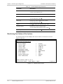
Monitoring the Status of the System ....................................................................... 5-2
Monitoring the Interface Status of the System ........................................................ 5-4
Monitoring the Physical Ports .................................................................................. 5-4
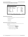
Monitoring the Status of the Ethernet Port ............................................................. 5-4
Monitoring the Status of the Uplink ........................................................................ 5-6
Monitoring the Status of the E1 Port....................................................................... 5-7
Detecting Problems .................................................................................................... 5-8
Power-Up Self-Test ................................................................................................. 5-8
Front Panel LEDs ..................................................................................................... 5-8
Alarms and Traps .................................................................................................... 5-8
Handling Events ......................................................................................................... 5-9
Displaying Events .................................................................................................... 5-9
Clearing Events ..................................................................................................... 5-10
Displaying Active Alarms ....................................................................................... 5-11
Masking Alarms ..................................................................................................... 5-12
Troubleshooting ....................................................................................................... 5-13
Performing Diagnostic Tests ..................................................................................... 5-14
Running Uplink Loopbacks..................................................................................... 5-15
Local Loopback on the Uplink ........................................................................... 5-15
Uplink Remote Loopback in Optimux-108 ......................................................... 5-15
Running Loopbacks on E1 Tributary Channels ........................................................ 5-16
E1 Tributary Local Loopback ............................................................................. 5-16
E1 Tributary Remote Loopback ......................................................................... 5-17
Running Loopbacks on V.35 User Port ................................................................... 5-18
Clearing Loopbacks ............................................................................................... 5-19
Frequently Asked Questions ..................................................................................... 5-20
Technical Support .................................................................................................... 5-20
Chapter 6. Software Upgrade
6.1
6.2
6.3
6.4
6.5
6.6
Compatibility Requirements ........................................................................................ 6-1
Impact ....................................................................................................................... 6-1
Software Upgrade Options ......................................................................................... 6-1
Prerequisites .............................................................................................................. 6-2
Software Files ......................................................................................................... 6-2
System Requirements ............................................................................................. 6-2
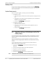
Upgrading Optimux-106 Software via the File Utilities Menu ....................................... 6-2
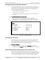
Verifying the Optimux-106 Host Parameters............................................................ 6-3
Activating the TFTP Server ....................................................................................... 6-4
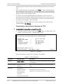
Downloading the New Software Release File to Optimux-106 .................................. 6-4
Downloading a New Software Release via TFTP................................................... 6-4
Downloading a New Software Release via XMODEM ............................................ 6-6
Upgrading Optimux-106 Software via the Boot Menu ................................................. 6-7
Using the XMODEM Protocol ................................................................................... 6-7
Using the TFTP ........................................................................................................ 6-9
Chapter 7. Configuring a Typical Application
7.1
7.2
Configuring the Optimux-108 Units ............................................................................ 7-1
Configuring the System Parameters ............................................................................ 7-2
Optimux-108 Ver. 6.1
iii
Table of Contents
Installation and Operation Manual
Appendix A. Pinouts
Appendix B. Boot Sequence and Downloading Software
iv
Optimux-108 Ver. 6.1
Chapter 1
Introduction
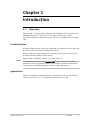
1.1
Overview
Optimux-108 is a second-order multiplexer that multiplexes four E1 channels and
100 Mbps Ethernet or V.35 link over a fiber optic link with various fiber
interfaces: multimode, single-mode (up to 120 km), and single-mode over single
fiber.
Product Options
The basic model includes a fiber optic uplink and four tributary E1 links, which can
be ordered with a balanced or unbalanced interface.
Optimux-108 can be also ordered with an additional Ethernet or V.35 user port,
and with redundant uplink or power supply.
Optimux-108 is available in a plastic or a metal enclosure.
Note
In this manual, the generic term Optimux-108 is used when the information is
applicable to all the equipment versions. The complete equipment designation is
used only for information applicable to specific equipment versions.
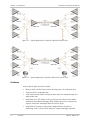
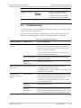
Applications
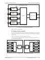
Figure 1-1 illustrates a typical application of the Optimux-108 unit with Ethernet
user port and Figure 1-2 – of the Optimux-108 with V.35 user port.
Optimux-108 Ver. 6.1
Overview
1-1
Chapter 1 Introduction
Installation and Operation Manual
Figure 1-1. Typical Application of Optimux-108 with Ethernet Port
Figure 1-2. Typical Application of Optimux-108 with V.35 User Port
Features
Various optical uplink interfaces include:
1-2
•
850 nm VCSEL (Vertical Cavity Surface Emitting Laser) for multimode fiber
•
1310 nm LED for multimode fiber
•
1310/1550 nm laser diode or long haul laser diode for extended range over
single-mode fiber
•
Single fiber (SF1, SF2 options) using a 1310 nm and 1550 nm laser diode
transmitter with WDM technology, which enables the laser to transmit the
signal at a different wavelength than the receive signal
•
Single fiber (SF3 option) using SC/APC (Angled Polished Connector)
technology, with a 1310 nm laser diode for single wavelength operation.
Overview
Optimux-108 Ver. 6.1
Installation and Operation Manual
Chapter 1 Introduction
The unit can be ordered with two uplink interfaces, where the second link
interface operates as a backup for the main link. The user can select automatic
switching to the backup or manual selection of the desired link interface.
Optimux-108 has comprehensive test and diagnostics capabilities that include
local and remote loopbacks on the uplink interface and on each E1 tributary link.
A local loopback is also supported on the optional V.35 user port.
To facilitate system diagnostics, Optimux-108 features LED status indicators, AIS
alarm generation and recognition, and dry contact closure upon link failure.
Optimux-108 can be powered from 100-240 VAC or –40 to -72 VDC. Two
independent power supplies can be installed, for redundancy.
Optimux-108 is a compact standalone unit. A rack mount adapter kit enables
installation of one or two (side-by-side) units in a 19-inch rack.
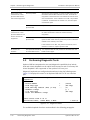
1.2
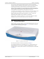
Physical Description
Optimux-108 is a 1U high, compact, easy-to-install standalone device. The front
view of the Optimux-108 unit is shown in Figure 1-3. The location of LEDs and
connectors on the metal enclosure is similar.
Figure 1-3. Optimux-108, 3D View
The front panel includes LED indicators described in Chapter 3.
The rear panel includes one or two uplink ports, 4 x E1 tributary interface, an
optional Ethernet or V.35 user port, an Ethernet management port, a serial
management port, and the power connector. The rear panel ports are described
in Chapter 2.
Optimux-108 Ver. 6.1
Physical Description
1-3
Chapter 1 Introduction
Installation and Operation Manual
1.3
Functional Description
Printed Circuit Boards
Optimux-108 contains the following printed circuit boards:
•
Main board, including two tributary interfaces (BNC interface board or RJ-45
connectors) and an optional user port. This user port can be a V.35 port
operating at fixed rate of 2.048 Mbps or an Ethernet port operating at up to
100 Mbps
•
One or two uplink interface boards (A and B)
•
One or two power supplies (A and B):
AC/DC wide-range power supply (100-240 VAC or -40 to -72 VDC)
Fiber Optic Uplink Interface
The fiber optic interface provides a secure link in hazardous or hostile
environments, increasing the maximum connection range, and achieving immunity
against electrical interference and protection against the harmful effects of
ground loops. To optimally meet a wide range of system requirements, the fiber
optic interface can be ordered for operation over 62.5/125 micron multimode
fibers (typical attenuation 3.5 dB/km at 850 nm), as well as over low-loss
9/125 micron single mode fibers (typical attenuation 0.4 dB/km at 1310 nm, and
0.25 dB/km at 1550 nm).
The fiber optic interface is hot swappable, allowing for quick and easy
replacement in the field.
Technical Characteristics
Table 1-1 provides information on the characteristics of the optical subsystem,
including the maximum range over typical fiber optic cable. The maximum range
values given in the table below assume a margin of 3 dB.
Table 1-1 Fiber Optic Interface Characteristics
Wavelength
Fiber Type
[nm]
[μm]
850
62.5/125 multimode
1310
Typical
Output
Power
[dBm]
Receiver
Typical Max.
Sensitivity Range
[dBm]
[km
Laser (VCSEL)
-6
-34*
4.5
9/125 single mode
Laser
-12
-34
47
1310
62.5/125 multimode
LED
-18
-32
7
1310
9/125 single mode
Laser
[long haul]
-2
-34
72
44.7
ST, SC, FC/PC
1310
Transmit/Receive
9/125 single mode
Single fiber
Laser [SF3]
-12
-27
20
12.4
SC/APC only
1310/1550
Transmit/Receive
9/125 single mode
Single fiber
Laser WDM
[SF1]
-12
-34
47
29.2
SC
1-4
Functional Description
Transmitter
Type
Connector
Type
miles]
2.8
ST, SC, FC/PC
29.2
ST, SC, FC/PC
4.3
ST, SC
Optimux-108 Ver. 6.1
Installation and Operation Manual
Chapter 1 Introduction
1550/1310
Transmit/Receive
9/125 single mode
Single fiber
Laser WDM
[SF2]
-12
-34
47
29.2 SC
1550
9/125 single mode
Laser
-12
-34
76
47.2
ST, SC, FC/PC
1550
9/125 single mode
Laser
[long haul]
-2
-34
120
74.5
ST, SC, FC/PC
* The Receiver Sensitivity for units with the Ethernet port is 32 dBm.
All fiber optic interface options offer high performance and have a wide dynamic
range.
Note
The SF3 option uses an SC/APC connector. The FO cable connected to it must
therefore be of the same type.
Uplink Redundancy Option
Optimux-108 can be ordered with one or two link interface options. Each
interface operates independently, and can be ordered from the link options listed
above.
In the uplink redundancy option, Optimux-108 supports fully automatic switching
between the main and the backup link. The main link has priority, therefore
normally it is selected for use, and the backup link is disabled. In case a failure
occurs on the main link, Optimux-108 automatically switches to the backup link
and continues providing normal service. After the main link returns to normal
operation, it is automatically reselected.
Each link interface has its own set of indicators that display the current state of
the link.
E1 Tributary Interface
The Optimux-108 tributary interfaces meet the requirements of ITU-T Rec. G.703.
The tributary ports (1-4) can be one of the following:
•
120Ω balanced line interface, terminated in a RJ-45 8-pin connector
•
75Ω unbalanced interface, terminated in two BNC coaxial connectors.
Line coding is HDB3. The nominal balanced interface transmit level is ±3V, and the
unbalanced interface transmit level is ±2.37V. The maximum line attenuation is up
to 6 dB, and each E1 signal is processed by an adaptive equalizer that
compensates for various cable lengths to ensure optimal performance. Phase
locked loops (PLL) are used to recover the clock signals, and the resulting jitter
performance complies with the requirements of ITU-T Rec. G.823.
Each tributary interface has its own set of indicators that show the current state
of the tributary link. The user can disable the alarm indications generated by
unused interfaces. AIS data streams are transmitted instead of failed or
unconnected tributary data streams.
Optimux-108 Ver. 6.1
Functional Description
1-5
Chapter 1 Introduction
Installation and Operation Manual
V.35 User Port
Optimux-108 can be also ordered with an additional V.35 user port. This port has
a V.35 DCE interface supporting both ISO 2110 and Telebras pinouts on DB-25
connectors and M34 connector pinout. All these pinouts are supported via
external cables.
Ethernet User Port
Optimux-108 can be also ordered with an additional Ethernet user port. This port
operates at a rate of 10/100 Mbps and can be set to 10/100 full or half duplex,
autonegotiation enable/disable. It supports flow control enable/disable option
and MDI/MDIX connection.
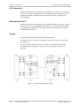
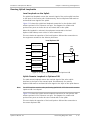
Timing
The uplink interface supports only internal timing mode.
The clock of each E1 channel is independent for each channel and transferred
transparently.
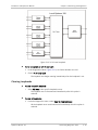
The V.35 interface supports internal, external, and loopback timing modes.
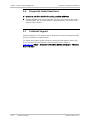
The figures below describe the three clock modes supported by the V.35
interface.
Figure 1-4. Internal and Loopback Timing
1-6
Functional Description
Optimux-108 Ver. 6.1
Installation and Operation Manual
INT DTE
CLK
Chapter 1 Introduction
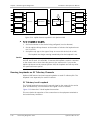
EXT
Figure 1-5. External and Loopback Timing
Test and Diagnostics Capabilities
Optimux-108 has comprehensive test and diagnostics capabilities that include
local and remote loopbacks on the uplink interface and on each E1 tributary link.
A local loopback is also supported on the optional V.35 user port.
Maintenance is further enhanced by an automatically performed self-test on
power up.
For activation of loopbacks, see Chapter 5.
Alarms and Alarm Indications
Uplink and Tributaries
Optimux-108 detects the following alarm conditions on each E1 and uplink
interface:
•
Loss of input signal
•
Loss of frame synchronization (on uplink only)
•
Reception of alarm indication (AIS) signal, which consists of a continuous
sequence of ‘1’s (on the tributary only)
When not all the tributaries are in use, you can disable the alarm indications
related to the unused tributaries through the software, see Chapter 5.
V.35 User Port
On the V.35 interface, Optimux-108 detects the Missing DTR signal (relevant only
for ISO 2110 pinout).
Note
This alarm should be masked when using Telebras and M34 cable (see Chapter 6).
Optimux-108 Ver. 6.1
Functional Description
1-7
Chapter 1 Introduction
Installation and Operation Manual
Response to Alarm Conditions
AIS is transmitted on each tributary output in the following cases:
•
Loss of uplink input signal is detected
•
Uplink frame synchronization is lost.
An AIS signal is sent on a tributary instead of the tributary data stream through
the uplink in the following cases:
•
Loss of tributary input signal is detected
•
AIS is received on the tributary input
•
Local Loop Back is activated on the E1 input.
Rear Panel Alarm Connector
An optional dedicated rear panel connector is used to provide major and minor
alarm indications, by means of dry contacts.
The major alarm is activated in the following cases:
•
Optimux-108 is not powered, or total power supply failure (e.g., when two
power supplies are installed, failure of both supplies)
•
One of two power supplies is faulty (optional, in case both power supplies
are installed)
•
Loss of uplink input signals, or loss of uplink frame synchronization
•
Signal loss at backup link while Link Redundancy mode is Automatic/Manual
•
Loss of tributary input signals
•
Redundancy mode is Automatic/Manual, but backup link is not installed
•
Unable to activate redundancy
•
MNG-ETH link failed
•
Missing DTR signal (relevant only for ISO 2110, masked for Telebras).
•
Connection with the remote device is lost.
The minor alarm is activated in the following case:
•
Reception of AIS signal on tributary inputs.
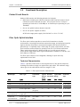
Events
Optimux-108 supports the following events, which are shown in the Event Log:
1-8
•
Failure in processing software download
•
Event log buffer has exceeded the maximum size and new events are written
over the old ones
•
Login was performed to the unit
•
Trying to log into the unit with wrong user name or password
•
Read/write via SNMP with wrong community
•
Unit is powered up
•
Uplink is switched from A to B and vice versa.
Functional Description
Optimux-108 Ver. 6.1
Installation and Operation Manual
Chapter 1 Introduction
Management
Optimux-108 can be configured and monitored locally via an ASCII terminal, or
remotely via Telnet, Web-based remote access terminal (ConfiguRAD) or
RADview-TDM running in a Windows or Unix environment.
Power
The power supply is a wide-range AC/DC power supply that can be connected to
either an AC power source (100 to 240 VAC), or to a DC power source
(–48 VDC).
Optimux-108 can be ordered with one or two power supplies. When two power
supplies are installed, they share the load. If one of the power supplies fails or its
input power is disconnected, the other one continues providing power to the unit.
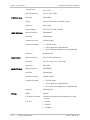
1.4
Uplink Interface
E1 Tributary
Interface
Technical Specifications
Number of Links
One or two (A and B)
Type
Fiber Optic
Performance
Refer to Table 1-1
Connectors
ST, SC, FC/PC, or SC/PC, ordered option
(SF1/SF2 options only available with SC)
(SF3 option only available with SC/APC)
Applicable Standards
ITU-T Rec. G.703, G.823
Nominal Line Data Rate
2048 kbps
Line Code
HDB3
Bit Rate Tolerance
±25 ppm
Line Impedance
120Ω (balanced) or 75Ω (unbalanced)
Connectors
Balanced interface: Shielded RJ-45 connector
Unbalanced interface: two BNC coaxial connectors
Signal Levels
Transmit level
Optimux-108 Ver. 6.1
Balanced Interface
±3V ±10%
Unbalanced
Interface
±2.37V ±10%
Technical Specifications
1-9
Chapter 1 Introduction
Installation and Operation Manual
Receive level
V.35 Interface
USER-ETH Port
Control Port
MNG-ETH Port
Timing
Jitter performance
Per ITU-T Rec. G.823
Data Rate
2.048 Mbps
Timing
Internal, External and Loopback Timing
Connector
Smart Serial
Control Signals
RTS, CTS, DTR, DSR, and DCD
Physical Interface
10/100BaseT
Data Rate
10/100 Mbps
Transmission Rate
Full/Half Duplex
Transmission Mode
•
Full/half-duplex
•
Auto-negotiation enable/disable
•
Flow Control and Backpressure enable/disable
Connector
Shielded RJ-45
Physical Interface
RS-232 DCE Asynchronous
Data Rate
9.6, 19.2, 38.4, 57.6, 115.2 kbps
Connector
Mini-USB 5
Physical Interface
10/100BaseT
Data Rate
10/100 Mbps
Transmission Rate
Full/Half Duplex
Transmission Mode
•
Full/half-duplex
•
Auto-negotiation enable/disable
•
Flow Control and Backpressure enable/disable
Connector
Shielded RJ-45
Uplink
Internal
E1 Tributary Channels
Transferred transparently, independent for each
channel
V.35 Port
1-10
0 to –6 dB
Technical Specifications
•
Internal
•
External
•
Loopback
Optimux-108 Ver. 6.1
Installation and Operation Manual
Diagnostics
Chapter 1 Introduction
Local and remote loopbacks on uplink and on each
E1 tributary link
Local loopback on optional V.35 user port
Indicators
Front Panel
PWR
On (green): both power supplies OK
On (red): power supply A fault
On (yellow): power supply B fault
Off: power supply fault
LINK A/B
On (red): Sync/Signal Loss on Link A/B
On (yellow): not used
Off: normal operation
CH1 to CH4
On (red): Signal Loss on channel
On (yellow): AIS received on channel
Off: normal operation
Rear Panel
Sig Link A/B (on the
fiber optic module)
Alarm Relay
Power
Physical
Optimux-108 Ver. 6.1
On (green): signal exists on Link A/B
Off: no signal on Link A/B
LINK/ACT
On (yellow): link is up
Off: link is down
Blinks: frames are transmitted
100
On (green): 100 Mbps mode
Off: 10 Mbps mode
Connector
Shielded RJ-45
Contact Functions
Set of floating normally-closed/normally open
contacts for major and minor alarm indication
Contact Rating
Maximum 0.5A (at 30 VDC or 30 VAC) through
closed contacts
Wide range AC/DC
Power Supply
100 to 240 VAC, 50 or 60 Hz, 25 VA
-48/60 VDC (-40 to-72 VDC), 9W
Plastic Enclosure
Height
4.37 cm / 1.7 in (1U)
Width
21.7 cm /8.5 in
Depth
17.0 cm / 6.7 in
Weight
0.5 kg / 1.1 lb
Technical Specifications
1-11
Chapter 1 Introduction
Installation and Operation Manual
Metal Enclosure
Environment
1-12
Height
4.73 cm (1.8 in)
Width
21.5 cm (8.4 in)
Depth
15.25 cm (6.0 in)
Weight
0.7 kg (1.5 lb)
Operating Temperature
0° to 50°C (32° to 122°F)
Relative Humidity
Up to 90%, non-condensing
Technical Specifications
Optimux-108 Ver. 6.1
Chapter 2
Installation and Setup
This chapter describes installation and setup procedures for the Optimux-108
unit.
After installing the unit, refer to Chapter 3 for the operating instructions. If a
problem is encountered, refer to Chapter 5 for test and diagnostic instructions.
Internal settings, adjustment, maintenance, and repairs may be performed only
by a skilled technician who is aware of the hazards involved.
Warning
Always observe standard safety precautions during installation, operation, and
maintenance of this product.
Note
Before installing the product, review Handling Energized Products at the
beginning of the manual.
2.1
Site Requirements and Prerequisites
The Optimux-108 device is intended for installation on desktop or 19” racks. The
RM-33-2 mounting kit is available from RAD for mounting 1 or 2 units in a
19” rack. For metal enclosure units RM-35 or WM-35 rack mount kits are
available.
Allow at least 90 cm (36 in) of frontal clearance for operating and maintenance
accessibility. Allow at least 10 cm (4 in) clearance at the rear of the unit for signal
lines and interface cables.
Avoid sharp bends when planning the routing of fiber optic cables.
The ambient operating temperature of Optimux-108 is 0 to 50°C (32 to 122°F),
at a relative humidity of up to 90%, non-condensing.
AC-powered Optimux-108 units should be installed within 1.5m (5 ft) of an
easily-accessible grounded AC outlet capable of furnishing the voltage in
accordance with Optimux-108 nominal supply voltage.
DC-powered Optimux-108 units require a -48 VDC power source, which must be
adequately isolated from the main supply.
Note
Refer also to the sections describing connections of AC and DC mains at the
beginning of the manual.
Optimux-108 Ver. 6.1
Site Requirements and Prerequisites
2-1
Chapter 2 Installation and Setup
2.2
Installation and Operation Manual
Package Contents
The Optimux-108 package contains the following items:
•
One Optimux-108 unit
•
AC power cable (two cables when ordered with redundant power supply)
•
DC adapter plug (two plugs when ordered with redundant power supply))
•
Technical Documentation CD
•
Control port cable: CBL-MUSB-DB9F
•
Alarm port cable: CBL-RJ45-DB9/F
•
V.35 interface cable (if V.35 interface is ordered):
CBL-AMP-M34 - Smart Serial to M34 interface
CBL-AMP-DB25-ISO2110 - Smart Serial to ISO 2110 interface
CBL-AMP-DB25-TLBS - Smart Serial to Telebras interface
•
RM-33-2 rack-mount kit (if ordered)
•
RM-35 or WM-35 rack mount kits for the metal enclosure unit (if ordered).
2.3
Required Equipment
The following equipment is required to install Optimux-108:
•
Fiber optic cables (for optical uplink interface)
•
RJ-45 E1 connector cables (for balanced tributary interface)
•
RJ-45 Ethernet connector cable category 5
•
Philips screwdriver (for installation in 19-inch rack).
2.4
Mounting the Unit
Optimux-108 is designed for installation as a desktop unit. It can also be
mounted in a 19" rack. For rack mounting instructions, refer to the RM-33-2
installation kit manual that comes with the RM kit for plastic enclosure unit and
RM-35 or WM-35 rack mount kits for the metal enclosure unit.
If Optimux-108 is to be used as a desktop unit, place and secure the unit on a
stable, non-movable surface.
Refer to the clearance and temperature requirements in Site Requirements and
Prerequisites.
2-2
Mounting the Unit
Optimux-108 Ver. 6.1
Installation and Operation Manual
2.5
Warning
Chapter 2 Installation and Setup
Connecting the Interfaces
Eye damage may be caused by a broken or unterminated fiber optic or connector
if the laser beam is viewed directly or with improper optical instruments. The
laser beam is invisible.
Access to the inside of the equipment is permitted only to qualified and
authorized service personnel.
Warning
Disconnect the unit from the power line and from all the cables before removing
cover.
Warning
Dangerous high voltages are present inside the Optimux-108 when it is
connected to power and/or to the links. Moreover, under external fault
conditions, dangerous high voltages may appear on the lines connected to the
Optimux-108.
Any adjustment, maintenance, and repair of the opened instrument under
voltage should be avoided as much as possible and, when inevitable, would be
carried out only by a skilled technician who is aware of the hazard involved.
Capacitors inside the instrument may still be charged even after the instrument
has been disconnected from its source of supply.
Caution Optimux-108 contains components sensitive to electrostatic discharge (ESD). To
prevent ESD damage, avoid touching the internal components.
Optimux-108 includes Class 1 lasers. For your safety:
Warning
• Do not look directly into the optical connectors while the unit is operating.
The laser beams are invisible.
• Do not attempt to adjust the laser drive current.
The use of optical instruments with this product will increase eye hazard. Laser
power up to 1 mW at 1300 nm and 1550 nm could be collected by an optical
instrument.
Use of controls or performing procedures other than those specified herein may
result in hazardous radiation exposure.
Connector Location
The following figures show two typical Optimux-108 plastic rear panels and
identify the connector locations. Figure 2-1 and Figure 2-2 show the unit with
the V.35 user port and, respectively, balanced and unbalanced tributaries.
Figure 2-3 and Figure 2-4 show the unit with the Ethernet user port and,
respectively, balanced and unbalanced tributaries. Figure 2-5 to Figure 2-8 show
a typical rear panels of the metal enclosure unit.
For connector pinout, see Appendix A.
Optimux-108 Ver. 6.1
Connecting the Interfaces
2-3
Chapter 2 Installation and Setup
Installation and Operation Manual
Figure 2-1 Plastic Enclosure, V.35 User Port and Unbalanced E1 Tributaries
Figure 2-2. Plastic Enclosure, V.35 User Port and Balanced E1 Tributaries
Figure 2-3 Plastic Enclosure, Ethernet User Port and Unbalanced E1 Tributaries
Figure 2-4. Plastic Enclosure, Ethernet User Port and Balanced E1 Tributaries
Figure 2-5 Metal Enclosure, V.35 User Port and Unbalanced E1 Tributaries
Figure 2-6. Metal Enclosure, V.35 User Port and Balanced E1 Tributaries
2-4
Connecting the Interfaces
Optimux-108 Ver. 6.1
Installation and Operation Manual
Chapter 2 Installation and Setup
Figure 2-7 Metal Enclosure, Ethernet User Port and Unbalanced E1 Tributaries
Figure 2-8. Metal Enclosure, Ethernet User Port and Balanced E1 Tributaries
Connecting the Uplink
Each fiber optic uplink interface is terminated in two ST, SC, FC-PC, or SC/APC
connectors, in accordance with the customer’s order.
For each uplink interface (A and B), connect as follows:
³
To connect the uplink:
1. Clean the optical connectors using an approved solvent, and dry thoroughly
using optical tissue.
2. Connect the cables to the two optical connectors designated TX (transmit
output) and RX (receive input) of the appropriate interface.
3. Note the correct connection of the transmit and receive cables to the
corresponding connectors. Avoid sharp bends and twisting of the fiber-optic
cables.
Notes
• Pay attention that SF1 must work opposite SF2 and not opposite the same
type of link.
• For WDM option, only one fiber optic cable per link should be connected.
Connecting the Tributary Interface
The tributary interface has four RJ-45 connectors (for the balanced link interface)
or four dual BNC connectors (for the unbalanced interface). For pin allocation of
the RJ-45 connectors, see Appendix A.
³
To connect the tributary interface:
•
Optimux-108 Ver. 6.1
Connect each of the tributary cables to the connector(s) of the
corresponding to the interface.
For the balanced interfaces, connect to the RJ-45 connectors designated
CH1, CH2, CH3, or CH4, respectively.
For the unbalanced interface, connect the cables to the two BNC
connectors designated IN (transmit input) and OUT (receive output) of
the appropriate interface. Note correct connection of the transmit and
receive cables to the IN and OUT connectors.
Connecting the Interfaces
2-5
Chapter 2 Installation and Setup
Installation and Operation Manual
Connecting the V.35 Interface
The Optimux-108 V.35 interface terminates in a 26-pin smart serial connector.
The pin assignment for the V.35 Interface connector (Smart serial) is given in
Appendix A.
³
To connect the V.35 Port:
•
Connect the DTE to the V.35 port using the required interface cable according
to the application: ISO 2110, Telebras or M34.
The following interface cables can be ordered from RAD.
Figure 2-9 shows the CBL-AMP-DB25-TLBS interface cable designed to connect
the Optimux-108 Smart serial interface connector to the user equipment DB-25
connector with Telebras pinout.
Figure 2-9. CBL-AMP-DB25-TLBS Cable
Figure 2-10 shows the CBL-AMP-DB25-ISO2110 interface cable designed to
connect the Optimux-108 Smart serial interface connector to the user equipment
DB25 connector with ISO 2110 pinout.
Figure 2-10. CBL-AMP-DB25-ISO2110 Cable
Figure 2-11 shows the CBL-AMP-M34 interface cable designed to connect the
Optimux-108 Smart serial interface connector to the M34 connector of the user
equipment.
2-6
Connecting the Interfaces
Optimux-108 Ver. 6.1
Installation and Operation Manual
Chapter 2 Installation and Setup
Figure 2-11. CBL-AMP-M34 Cable
Connecting the User Ethernet Port
The user Ethernet port interface terminates in an 8-pin RJ-45 connector.
³
To connect the User Ethernet Port:
•
Connect the Ethernet user equipment to the MNG-ETH connector using a
UTP-CAT5 cable.
Alarm Connector
This connector connects the changeover contacts of the major (optinally, minor)
alarm relays to the external equipment. Connection of the alarm port is made
using a special cable with RJ-45 connector and DB9-female connector –
CBL-RJ45-DB9/F, shown in Figure 2-12.
Figure 2-12. Alarm Cable - CBL-RJ45-DB9/F
³
To connect the alarm connector to the external equipment:
1. Connect the RJ-45 connector of the CBL-RJ45-DB9/F cable to the ALARM
connector located on the Optimux-108 rear panel.
2. Connect the external DB9-female connector of the CBL-RJ45-DB9/F cable to
the external equipment.
Connecting the Ethernet Management Port
The Ethernet Management Port interface terminates in an 8-pin RJ-45 connector.
³
To connect the Ethernet Management port:
•
Optimux-108 Ver. 6.1
Connect the management station to the MNG-ETH connector using a
UTP-CAT5 cable.
Connecting the Interfaces
2-7
Chapter 2 Installation and Setup
Installation and Operation Manual
Connecting the Control Port
The optional Optimux-108 supervisory port has a standard RS-232 DCE interface.
RAD supplies a special control cable, CBL-MUSB-DB9F (see Figure 2-13), for
connection of this mini USB connector to the supervision terminal.
Figure 2-13. Control Cable
³
To connect the control port:
•
Connect the control cable to the mini USB connector at the rear panel and to
the DCE device, using the CBL-MUSB-DB9F control cable.
2.6
Connecting to Power
Optimux-108 accepts either 110–240 VAC or -48/-60 VDC power through the
same power inlet.
Warning
Before connecting or disconnecting any cable, the protective earth terminals of
this unit must be connected to the protective ground conductor of the mains (AC
or DC) power cord. If you are using an extension cord (power cable) make sure it
is grounded as well.
Any interruption of the protective (grounding) conductor (inside or outside the
instrument) or disconnecting of the protective earth terminal can make this unit
dangerous. Intentional interruption is prohibited.
Note
Refer also to the sections describing connections of AC and DC power at the
beginning of the manual.
Connecting to AC Power
AC power should be supplied via a 1.5m (5 ft) standard power cable terminated
by a standard 3-prong socket. A cable is provided with the unit.
³
To connect AC power:
1. Connect the power cable to the connector on the Optimux-108 rear panel.
2. Connect the power cable to the electricity outlet.
3. In the case of the redundant power supply, repeat the procedure.
The unit turns on automatically upon connection to the mains.
2-8
Connecting to Power
Optimux-108 Ver. 6.1
Installation and Operation Manual
Chapter 2 Installation and Setup
Connecting to DC Power
A special IEC 60320 adapter for the -48/-60 VDC power connection is supplied
with the unit.
³
To connect DC power:
•
Caution
Refer to the DC power supply connection supplement for instructions how to
wire the DC adapters. The DC supplement is provided on the technical
documentation CD supplied with the unit.
The DC installation procedure must be performed by a qualified technician.
Optimux-108 Ver. 6.1
Connecting to Power
2-9
Chapter 2 Installation and Setup
2-10
Connecting to Power
Installation and Operation Manual
Optimux-108 Ver. 6.1
Chapter 3
Operation
3.1
³
Turning On the Unit
To turn on an Optimux-108 unit with a single power supply:
1. Connect the power cable to the power connector on the rear panel of the
Optimux-108.
2. Connect the power cable to the electric outlet.
The PWR indicator lights in green.
³
To turn on an Optimux-108 unit with two power supply units:
1. Connect each power cable to a power connector on the Optimux-108 rear
panel.
2. Connect each power cable to the electricity outlet.
The PWR indicator lights in green.
3.2
Indicators
Front Panel Indicators
Figure 3-1 shows the Optimux-108 front panel. Table 3-1 lists the functions of
the front panel indicators.
Figure 3-1 Optimux-108 Front Panel
Table 3-1. Optimux-108 Indicators
LED Function
Color
Meaning
PWR
Green
Power supplies A and B are functioning correctly or PSA is good and PSB
is not installed or PSB is good and PSA is not installed
Red
PSA exists but is faulty
Optimux-108 Ver. 6.1
Indicators
3-1
Chapter 3 Operation
LED Function
Link A
Link B
CH1
CH2
CH3
CH4
Installation and Operation Manual
Color
Meaning
Yellow
PSB exists but is faulty
Off
Power is Off
Red
Signal loss or sync. loss detected
Off
Normal operation – no alarm is detected, or power is Off
Red
Signal loss or sync. loss detected
Off
Normal operation – no alarm is detected, or power is Off
Yellow
AIS detected on E1 Ch1
Red
Signal loss detected on E1 CH1
Off
Normal operation – no alarm is detected, or power is Off
Yellow
AIS detected on E1 Ch2
Red
Signal loss detected on E1 CH2
Off
Normal operation – no alarm is detected, or power is Off
Yellow
AIS detected on E1 Ch3
Red
Signal loss detected on E1 CH3
Off
Normal operation – no alarm is detected, or power is Off
Yellow
AIS detected on E1 Ch4
Red
Signal loss detected on E1 CH4
Off
Normal operation – no alarm is detected, or power is Off
During normal operation:
•
The PWR indicator lights in green.
•
The indicator corresponding to the uplink in use, A or B, lights.
•
All SYNC LOSS front-panel indicators are turned off.
Rear Panel Indicators
Figure 3-2 shows the rear panel of an Optimux-108 model with the user Ethernet
port. Table 3-1 lists the functions of the rear panel indicators.
Figure 3-2. Optimux-108 Rear Panel
3-2
Indicators
Optimux-108 Ver. 6.1
Installation and Operation Manual
Chapter 3 Operation
Table 3-2. Optimux-108 Rear Panel Indicators
LED Function
Color
Meaning
USER ETH: LINK/ACT
Yellow
On - USER link is up
Blinking yellow
USER link is up and Rx and/or Tx frames are
being transmitted
Yellow
Off – Management link is down
Green
On – 100M mode
USER ETH: 100
Off – 10M mode
MNG ETH: LINK/ACT
MNG. ETH: 100
Yellow
On - Management link is up
Blinking yellow
Management link is up and Rx and/or Tx frames
are being transmitted
Yellow
Off – Management link is down
Green
On – 100M mode
Off – 10M mode
SIG (located on the bottom
of the fiber optic module)
3.3
Green
On – Signal is detected on fiber optic module
Off – signal not detected
Default Settings
Table 3-3 lists the default settings of the Optimux-108 configuration parameters.
Table 3-3. Default Settings
Type
Parameter
Default Value
Name
Optimux-108
Location
The Location of the Device
Contact Person
Name of Contact Person
IP address
0.0.0.0
IP mask
0.0.0.0
Default gateway
0.0.0.0
Read Community
public
Write Community
private
Trap Community
public
Telnet
All
SNMP
All
Web
All
System
Device Information
Host
Management Access
Optimux-108 Ver. 6.1
Default Settings
3-3
Chapter 3 Operation
Type
Control Port
Installation and Operation Manual
Parameter
Default Value
Baud rate
115200
Security timeout
10
Pop alarms
Off
Fault Propagation
Alarms
Redundancy
Off
Device
Local
Alarms
Unmasked
Remote Connection Fall
Unmasked
Force Link
Link A
Mode
Auto
Device Number
Local
Port Number
MNG-ETH
Port Name
-
Auto Negotiation
Enable
Flow Control
Disable
Alarms
Unmasked
Device Number
Local
Administrative Status
Up
Port Name
-
Clock Source
Internal
DCD Status
Permanent ON
CTS Status
Permanent ON
DTE Loop Detection
Disable
Alarms
Unmasked
Device Number
Local
Port Number
Link A
Port Name
-
Alarms
Unmasked
Device Number
Local
Port Number
1
Port Name
-
Alarms
Unmasked
Device Number
Local
Link Loop type
No Loop
Physical Layer
Ethernet
V.35
Link
E1
Diagnostics
3-4
Default Settings
Optimux-108 Ver. 6.1
Installation and Operation Manual
Type
3.4
Chapter 3 Operation
Parameter
Default Value
Link LLB loop timeout (min)
[1-255]
5
Channel’s Loops
No Loop
Configuration and Management Alternatives
After installation, there are no special operating procedures for Optimux-108.
Once it is powered up, the unit operates automatically. The unit operational
status can be monitored constantly.
If required, Optimux-108 can be reconfigured. Optimux-108 can be managed
using different ports and applications:
•
Local out-of-band management via an ASCII terminal connected to the
RS-232 port. Usually, preliminary configuration of the system parameters is
performed via ASCII terminal. Once the Optimux-108 host IP parameters are
set, it is possible to access it via Telnet, ConfiguRAD or RADview for further
configuration.
•
Remote management via Ethernet management port. Remote management is
performed using Telnet, or ConfiguRAD (RAD’s Web-based application), or
RADview-PC/TDM and RADview-HPOV/TDM (RAD’s SNMP-based management
systems). Alternatively, Optimux-108 can be managed via a third-party SNMPbased NMS.
Optimux-108 allows up to three management sessions to be active at a time. This
includes up to two network sessions (Telnet or ConfiguRAD) and one ASCII
terminal session. When connected via Telnet or Web, the user is disconnected
after 10 minutes of inactivity (no keyboard input on the client computer).
The following functions are supported by the Optimux-108 management
software:
•
Viewing system information (Inventory)
•
Modifying configuration and mode of operation, including setting system
default values and resetting the unit
•
Monitoring Optimux-108 performance
•
Initiating loopback tests (Diagnostic)
•
Uploading and downloading software and configuration files.
Working with Terminal
Optimux-108 has a V.24/RS-232 asynchronous DCE port, designated CONTROL
and terminated in a 9-pin D-type female connector. The control port continuously
monitors the incoming data stream and immediately responds to any input string
received through this port.
The Optimux-108 control port can be configured to communicate at the following
rates: 9.6, 19.2, 38.4, 57.6 or 115.2 kbps.
Optimux-108 Ver. 6.1
Configuration and Management Alternatives
3-5
Chapter 3 Operation
³
Installation and Operation Manual
To start a terminal control session:
1. Make sure all Optimux-108 cables and connectors are properly connected.
2. Connect Optimux-108 to a PC equipped with an ASCII terminal emulation
application (for example, Windows Hyper Terminal or Procomm).
3. Turn on the control terminal PC and set its port parameters to 115,200 baud,
8 bits/character, 1 stop bit, no parity, flow control: none.
4. Set the terminal emulator to VT100 emulation (for optimal view of system
menus).
5. If you are using Hyper Terminal, set the terminal application under windows
system to 132-column mode for optimal view of system menus (Properties >
Settings > Terminal Setup > 132 column mode).
6. When the initialization and self-test are over, press any key to display the
user name and password entry fields.
Login
To prevent unauthorized modification of the operating parameters, Optimux-108
supports two access levels:
•
Superuser can perform all the activities supported by the Optimux-108
management facility, including defining new users.
•
User’s access rights (full control or read only) are defined by the superuser.
Users are not allowed to create new users.
1. After the SW finishes uploading, press Enter a few times.
"..." appears.
2. Press <.> a few times until the following Password Prompt screen appears.
(This synchronizes the baud rate of the terminal to the setup configuration).
Optimux-108
USER NAME:
PASSWORD:
SU
****
ESC - clear; & - exit;
0 M/ 1 C
Figure 3-3. Password Prompt Screen
Note
³
It is recommended to change default passwords to prevent unauthorized access
to the unit.
To enter as a superuser:
1. Enter su for user name.
2. Enter 1234 for password.
This allows you to configure all the parameters of Optimux-108, and to change
the
su and user passwords.
3-6
Configuration and Management Alternatives
Optimux-108 Ver. 6.1
Installation and Operation Manual
³
Chapter 3 Operation
To enter as a user:
1. Enter user for user name.
2. Enter 1234 for password.
³
To set all passwords to the default values (1234):
•
Log in as su and delete the unit’s configuration through the configuration
screens.
Choosing Options
³
How to use the terminal to perform a desired activity:
•
To select a menu item, type the corresponding line number and then press
<Enter>. This will either …
… display a submenu or a parameter selection screen …
or …
… let you type the (free text) parameter value in the same row
or …
… toggle the current value of the corresponding parameter (relevant to
ENABLE/DISABLE or ON/OFF selections).
•
The type of response to be expected after selecting a menu item is indicated
as follows:
>
Selecting that item will display a submenu or a parameter
selection screen.
...
Selecting that item will let you type the desired value in the
same line.
Nothing
When neither symbol is displayed, selecting that item will toggle
the current selection, now shown in brackets (for example, this
will change ENABLE to DISABLE or vice versa).
Navigating the Screens
•
•
•
Optimux-108 Ver. 6.1
The following hot keys are provided for navigating the screens:
Esc – Return to previous menu
! – Return to the main menu
& – Exit to password screen (to prevent unauthorized access after
completing the session)
When a menu does not fit on one screen (because it includes many lines), it
is displayed on two consecutive pages. In this case:
Press D to browse forward (down)
Press U to browse backward (up).
When a configuration screen is organized as a table, a special set of keys is
used for navigation within the table (such screens always have a ? (help)
Configuration and Management Alternatives
3-7
Chapter 3 Operation
Installation and Operation Manual
option that displays these keys). The following keys may be used for
navigation within tables:
L – move to the left
R – move to the right
In addition, the following shortcuts are also available:
•
Tab – select the next cell that may be changed
S followed by <row number>,<col number> – select a specific cell. For
example, type S2,5 to select the fifth cell in the second row.
The current value of a parameter is listed within parentheses ( ). To change a
parameter value on a parameter selection screen:
Type the line number corresponding to the desired value, and then press
<Enter>
To enter a value which requires free text entry, type in the desired string
and then press <Enter>. Use backspace to erase the current string.
Note that whenever applicable, the allowed range of values of a
parameter is listed within square brackets [ ].
•
•
The entry is checked after pressing <Enter>, and it is accepted only if it is
valid:
If you make an error, for example, if you press a key not active on the
current screen or select an invalid parameter value, an ERROR indicator
appears in the right-hand corner. This indicator disappears as soon as
you make a correct operation.
If you select a parameter value incompatible with the current operating
state or other parameters, you will see a message that explains the error.
When done with the current screen, press <Esc> to return to the previous
screen, or type ! to return directly to the main menu.
Ending a Terminal Configuration Session
³
To end the current terminal session:
•
Type &.
After a session is ended, it is necessary to enter again a valid user name and
password to start a new session.
Working with Web Terminal
Web Browser Requirements
The following Web browsers can be used to access the Optimux-108 supervision
utility from any location that enables access to the Optimux-108 using Internet
protocols.
3-8
•
Internet Explorer 6.0 and up, running on Windows™
•
Netscape Communicator 7.0 and up, running on Windows™, HPOV or Linux
•
Firefox 1.0.4 and up, running on Windows™
Configuration and Management Alternatives
Optimux-108 Ver. 6.1
Installation and Operation Manual
•
Chapter 3 Operation
Mozilla 1.4.3 and up, running on Linux.
However, before using Web access, it is necessary to perform a preliminary
configuration of Optimux-108.
When using a Web browser, pay attention to the following points:
•
Enable scripts
•
Configure the firewall that is probably installed on your PC in order to allow
access to the destination IP address
•
Disable pop-up blocking software (such as Google Popup Blocker); you may
also have to configure your spyware/adware protection program to accept
traffic from/to the destination IP address
•
Browsers store the last viewed pages in a special cache. To prevent
configuration errors, it is absolutely necessary to flush the browser’s cache
whenever you return to the same screen.
Login
³
To manage Optimux-108 via Web browser:
1. Open the Web browser.
2. Enter the IP address of Optimux-108 in the address field of the browser in
the following format: http://’IP address’ (‘IP address’ stands for the actual
Optimux-108 IP address).
3. After entering the address, press <Enter> to command the browser to
connect.
4. After the opening window is displayed (Figure 3-4), click LOGIN.
Optimux-108 Ver. 6.1
Configuration and Management Alternatives
3-9
Chapter 3 Operation
Installation and Operation Manual
Figure 3-4. Web Browser Access, Typical Log-in Window
Figure 3-5. Web Browser Access, User Name and Password Entry Window
3-10
Configuration and Management Alternatives
Optimux-108 Ver. 6.1
Installation and Operation Manual
Chapter 3 Operation
5. In the Password Entry window (Figure 3-5), log in by entering your user name
(user) and password (1234).
The Main menu is displayed (Figure 3-6).
Figure 3-6. Web Browser Access, Typical Main Menu Window
6. Use standard browser operating procedures to perform the desired activities.
Notes
• It is recommended to change default passwords to prevent unauthorized
access to the unit.
• Optimux-108 allows up to three management sessions to be active at a time.
This includes up to two network sessions (Telnet, ConfiguRAD, RADview) and
one ASCII terminal session.
• If no user input is detected for 5 minutes during ConfiguRAD session,
Optimux-108 automatically disconnects from the management station.
Navigating the ConfiguRAD Menus
ConfiguRAD is a Web-based remote access terminal management software. It
provides a user-friendly interface for configuring, monitoring and performing
diagnostic tests on the Optimux-108 units.
³
To choose an option:
1. Click a link in the ConfiguRAD screen to display the next menu.
2. Once the target screen is displayed, select a value from the drop-down box or
enter it in a text box.
Optimux-108 Ver. 6.1
Configuration and Management Alternatives
3-11
Chapter 3 Operation
Installation and Operation Manual
At the left-hand bottom corner ConfiguRAD provides some auxiliary management
tools:
•
•
•
Status – shows the number of users currently managing Optimux-108
Trace – opens an additional pane for system messages, progress indicators
(ping, software and configuration file downloads) and alarms. It is
recommended to keep the trace pane open all the time.
Refresh All – refreshes all ConfiguRAD display elements.
Working with SNMP-based Management System
RADview-PC/TDM and RADview-HPOV/TDM
RADview-PC and RADview-HPOV are user-friendly and powerful SNMP-based
element management systems, used for planning, provisioning, and managing
heterogeneous networks. RADview software provides a graphical user interface
for monitoring RAD products via their SNMP agents.
RADview management software for Optimux-108 is bundled in the
RADview-PC/TDM and RADview-HPOV/TDM packages for PC (Windows-based) or
Unix, respectively.
For more details about this network management software, and for detailed
instructions on how to install, set up, and use RADview, contact your local
Authorized Business Partner or refer to the RADview-PC/TDM and
RADview-HPOV/TDM User's Manuals, located on the Technical Documentation CD
or on RAD's Web site.
Third-party SNMP-based NMS
Alternatively, Optimux-108 can be managed via a third-party SNMP-based NMS.
Optimux-108 supports several management information bases (MIBs). A MIB
(Management Information Base) is a database of managed objects. The MIB
contains the data regarding the network elements being controlled and
monitored. Each characteristic of the element to manage is defined as an object
in the MIB. The MIB is a hierarchical tree structure that acts as the repository for
defined objects. Each object has an object name, a type, syntax, an access code
(read-write, read-only, not-accessible, and write-only) and a status (mandatory,
optional, obsolete).
Optimux-108 supports appropriate groups (tables) of MIB II (SNMP standard MIB),
and the RAD Private MIB as follows:
3-12
MIB
Notes
Tables
RFC3418
MIB-II
IANAiftype
RFC2863
MIB-II
if
RFC3593
MIB-II
PreHist-TC
RFC3895
Partially supported
dsx1ConfigTable
Configuration and Management Alternatives
Optimux-108 Ver. 6.1
Installation and Operation Manual
Chapter 3 Operation
MIB
Notes
Tables
RAD Private MIB
Partially supported
–
– radGen
physicalConnectorTable
– optimux
mngTrapIPTable
agnTrapMask (object) agnLed (object)
OptMxConfigTable
Additional MIB information can be obtained from your local Authorized Business
Partner.
For the trap list, see Chapter 5
3.5
Menu Map
Use the terminal menus to set and view configuration parameters. Figure 3-7
illustrates the main menu and its submenus. Use this tree as a reference aid
while performing configuration and control functions. Refer to Chapter 4 and
Chapter 5 to find specific parameters.
Main Menu
1. Inventory
2. Configuration
3. Monitoring
1. Device Number
4. Diagnostics
1. System
5. Utilities
1. Device Number
1. Active Alarms
2. Link Loop type
2. Event Log
3. Link LLB Loop
Timeout (min) [1-255]
3. Status
4. Interface Status
5. Clear Log File
2. Physical Layer
1. File Utilities
1. File System SW
1. Software Files
2. SWAP SW Files
4. Channel’ Loops
2. SW & File Transfer
5. V.35 Loop Type
1. TFTP
6. Clear All E1 Loops
1. Server IP
1. Ethernet
2. Remote File Name
2. Link
3. Command
2. XMODEM
1. Device Number
2. Reset Device
2. Port Number
3. E1
1. Device Number
2. Port Number
4. V.35
1. System
2. Physical Layer
1. Device Number
4. V.35
1. Device Number
2. Administrative Status
1. Ethernet
2
2. Link
3. E1
3. Port Name
1. Device Number
1. Device Number
1. Device Number
4. Clock Source
2. Port Number
2. Port Number
2. Port Number
5. DCD Status
3. Port Name
3. Port Name
3. Port Name
6. CTS Status
4. Auto Negotiation
4. Alarms
4. Alarms
7. DTE Loop Detection
5. Flow Control
8. Alarms
Figure 3-7. Main Menu Tree - Optimux-108 with V.35 User Port
Optimux-108 Ver. 6.1
Menu Map
3-13
Chapter 3 Operation
Installation and Operation Manual
Main Menu
2. Configuration
1. System
2
1. Management
2. Control Port
1. Device Information
3. Fault Propagation
4. Alarms
5. Redundancy
6. Factory Default
1. Baud Rate
1. Device Number
1. Name
2. Security Timeout
2. Alarms
1. Force Link
2. Location
3. Pop Alarms
3. Remote Connection Fail
2. Mode
3. Contact
1. Local Redundancy
1. All
2. W/O Management
2. Remote Redundancy
2 Host
1. Force Link
2. Mode
1. IP Address
2. IP Mask
3. Default Gateway
4. Read Community
5. Write Community
6. Trap Community
3. Managers List
4. Management Access
1. User Access
1. Change Password
2. User Info
2. Telnet
3. Web
4. SNMP
Figure 3-8. Main Menu Tree - Optimux-108 with V.35 User Port (cont.)
Main Menu
1. Inventory
2. Configuration
3. Monitoring
1. Device Number
4. Diagnostics
1. System
1. Device Number
1. Active Alarms
2. Link Loop Type
2. Event Log
3. Link LLB Loop Timeout
3. Status
4. Channel’s Loops
4. Interface Status
5. Clear Log File
2. Physical Layer
1. Ethernet
1. Device Number
5. Clear All Channel’s Loops
5. Utilities
1. File Utilities
1. File System SW
1. Software Files
2. SWAP SW Files
2. SW & File Transfer
1. TFTP
1. Server IP
2. Remote File Name
3. Command
1. No Operation
2. Port Number
2. SW Download
2. Link
3. SW Upload
1. Device Number
4. Configuration File Download
2. Port Number
5. Configuration File Upload
3. E1
1. Device Number
1. System
2. Physical Layer
1. Ethernet
1. Port Number
2
2. Link
2. Port Number
2. Reset Device
3. E1
1. Device Number
1. Device Number
1. MNG-ETH
2. Port Number
2. Port Number
2. USER-ETH
3. Port Name
3. Port Name
4. Alarms
4. Alarms
2. Port Name
2. XMODEM
3. Auto Negotiation
4. Flow Control
5. Alarms
Figure 3-9. Main Menu Tree - Optimux-108 with Ethernet User Port
3-14
Menu Map
Optimux-108 Ver. 6.1
Installation and Operation Manual
Chapter 3 Operation
Main Menu
2. Configuration
1. System
2
1. Management
2. Control Port
1. Device Information
3. Alarms
4. Redundancy
1. Baud Rate
1. Device Number
1. Name
2. Security Timeout
2. Alarms
1. Force Link
2. Location
3. Pop Alarms
3. Remote Connection Fail
2. Mode
3. Contact
1. Local Redundancy
5. Factory Default
1. All
2. W/O Management
2. Remote Redundancy
2 Host
1. Force Link
1. IP Address
2. Mode
2. IP Mask
3. Default Gateway
4. Read Community
5. Write Community
6. Trap Community
3. Managers List
4. Management Access
1. User Access
1. Change Password
2. User Info
2. Telnet
3. Web
4. SNMP
Figure 3-10. Main Menu Tree - Optimux-108 with Ethernet User Port (cont.)
3.6
³
Turning Off the Unit
To power off the unit:
•
Optimux-108 Ver. 6.1
Remove the power cord from the power source.
Turning Off the Unit
3-15
Chapter 3 Operation
3-16
Turning Off the Unit
Installation and Operation Manual
Optimux-108 Ver. 6.1
Chapter 4
Configuration
This chapter illustrates the configuration Optimux-108 screens and explains their
parameters.
Menu trees of the Optimux-108 management software are shown in Chapter 3.
4.1
Configuring Optimux-108 for Management
Usually, initial configuration of the management parameters is performed via an
ASCII terminal. Once the Optimux-108 host IP parameters are set, it is possible to
access it via Telnet, ConfiguRAD or RADview for operation configuration. Perform
the following steps in order to configure Optimux-108 for management:
•
Setting the Device Information
•
Configuring IP Host Parameters
•
Configuring Optimux-108 Communities
•
Configuring the Network Managers
•
Setting up the Managers List
•
Controlling Management Access.
Entering Device Information
The Optimux-108 management software allows you to assign a name to the unit,
add its description, specify its location to distinguish it from the other devices
installed in your system, and assign a contact person.
³
To enter device information:
1. From the System menu, select Management.
2. From the Management menu, select Device Information.
The Device Information menu appears (see Figure 4-1).
3. From the Device Information menu, select Name and enter a desired name
for the Optimux-108 unit.
4. Select Location and enter the desired name for the current Optimux-108
location.
5. Select Contact and enter the name, phone, and/or any other details of the
contact person you want to save in this field.
Optimux-108 Ver. 6.1
Configuring Optimux-108 for Management
4-1
Chapter 4 Configuration
Installation and Operation Manual
Optimux-108
Configuration>System>Management>Device Information
Description
1. Name
2. Location
3. Contact
...
...
...
...
(OP-108 HW Version:0.00/A, SW Version:6.10)
(Optimux-108)
(The location of this device)
(Name of contact person)
>
Please select item <1 to 3>
ESC-Previous menu; !-Main Menu; &-Exit
Figure 4-1. Device Information Menu
Configuring IP Host Parameters
When you integrate the Optimux-108 into your network, you will need to set the
network parameters of the Optimux-108.
³
To define the IP parameters:
1. From the Management menu, select Host.
The Host menu is displayed (see Figure 4-2).
2. From the Host menu, perform the following:
Note
Select IP Address to define the host IP address
Select IP Mask to define the host IP mask.
Select Default Gateway to set the default gateway IP address
The default gateway must be in the same subnet as the host.
Optimux-108
Configuration>System>Management>Host
1.
2.
3.
4.
5.
6.
IP Address
IP Mask
Default Gateway
Read Community
Write Community
Trap Community
...
...
...
...
...
...
(0.0.0.0)
(0.0.0.0)
(0.0.0.0)
(public)
()
()
>
Please select item <1 to 6>
ESC-Previous menu; !-Main Menu; &-Exit
Figure 4-2. Host Menu
Configuring Optimux-108 Communities
For establishing a proper management link, you must specify the SNMP trap, read
and write communities.
4-2
Configuring Optimux-108 for Management
Optimux-108 Ver. 6.1
Installation and Operation Manual
³
Chapter 4 Configuration
To configure Optimux-108 communities:
1. From the Management menu, select Host.
The Host (Management) menu is displayed (see Figure 4-2).
2. From the Host menu, do the following:
Select Read Community to enter the name of a community with read-only
authorization.
Select Write Community to enter the name of a community with write
authorization.
Select Trap Community to enter the name of a community to which
Optimux-108 sends traps.
Setting up the Manager List
By default, any remote management terminal is allowed to change the
configuration of the Optimux-108. You may enhance the security of the site by
limiting remote management to specific management terminals or nodes. The
Manager List lists the network nodes from which management may take place.
Optimux-108
Configuration>System>Management>Managers List
Num
1
2
3
4
5
6
7
8
9
10
IP Address
(0.0.0.0)
(0.0.0.0)
(0.0.0.0)
(0.0.0.0)
(0.0.0.0)
(0.0.0.0)
(0.0.0.0)
(0.0.0.0)
(0.0.0.0)
(0.0.0.0)
Trap
Unmasked
Unmasked
Unmasked
Unmasked
Unmasked
Unmasked
Unmasked
Unmasked
Unmasked
Unmasked
1. Change Cell
... (0.0.0.0)
>
ESC-Previous menu; !-Main Menu; &-Exit; ?-Help
Figure 4-3. Managers List Screen
³
To define the managers list:
1. The list contains 10 entries. Press D to move down the list; press U to move
up the list. Press L to select the previous field; press R to select the next
field.
2. To change the value of a field, select the field (it will appear highlighted),
then choose Change Cell and then enter the new value.
When the Trap field is set to Unmasked, a trap is sent to this agent.
Optimux-108 Ver. 6.1
Configuring Optimux-108 for Management
4-3
Chapter 4 Configuration
Installation and Operation Manual
Controlling Management Access
You can enable or disable access to the Optimux-108 management system via an
SNMP, Telnet or Web-based application. By disabling SNMP, Telnet or Web, you
prevent unauthorized access to the system when security of the Optimux-108 IP
address has been compromised. When SNMP, Telnet and Web access is disabled,
Optimux-108 can be managed via an ASCII terminal only. In addition, you can limit
access to the device to only the stations defined in the manager list. Figure 4-4
details management access implementation, depending whether the network
managers are defined or not.
³
To define the management access method:
1. From the Management menu, select Management Access.
The Management Access menu appears (see Figure 4-4).
Optimux-108
Configuration>System>Management>Management Access
1.
2.
3.
4.
User Access
Telnet
WEB
SNMP
>
>
>
>
(All)
(All)
(All)
>
Please select item <1 to 4>
ESC-Previous menu; !-Main Menu; &-Exit
Figure 4-4. Management Access Menu
2. From the Management Access menu, select Telnet to configure Telnet access,
select SNMP to configure SNMP access, or select WEB to configure Web
access.
3. Define access mode for each management method:
All (access is allowed for all stations)
None (access is not allowed)
Manager Only (access is allowed only for the stations appearing in the
manager list).
Listing Users
The following screen lists information about all users defined in the device.
Optimux-108
. . . >User Info
1
2
User Name
USER
SU
Access level
RO
RW
Dynamic/Permanent
Permanent
Permanent
ESC-Previous menu; !-Main Menu; &-Exit; ?-Help
Figure 4-5. User Information Screen
4-4
Configuring Optimux-108 for Management
Optimux-108 Ver. 6.1
Installation and Operation Manual
Chapter 4 Configuration
Table 4-1. User Information Fields
Field
Possible
Values
Description
User Name
Access level
Dynamic/Permanent
Name of user defined in the device.
RO
Read Only. This user can display information,
but cannot modify parameters.
RW
Read/Write. This user has full control over the
device and can modify parameters.
Permanent
Indicates whether this user name is built into
the system or added by an administrator.
Built-in users are permanent.
Dynamic
Configuring Control Port Parameters
Optimux-108 embedded software enables you to configure the serial port parameters,
which include specifying terminal baud rate, controlling pop alarms and security
timeout.
³
To access the Control Port menu:
•
From the System Configuration menu, select Control Port.
The Control Port menu appears (see Figure 4-6).
Optimux-108
Configuration>System>Control Port
1. Baud rate
2. Security Timeout
3. Pop Alarms
>
(115200 bps)
(10 min.)
(ON)
>
Please select item <1 to 3>
ESC-Previous menu; !-Main Menu; &-Exit
Figure 4-6. Control Port Menu
³
To configure the control port data rate:
1. From the Control Port menu, select Baud Rate.
The Baud Rate menu appears (see Figure 4-7).
2. Select the terminal rate by typing the number corresponding to the desired
value, and pressing <Enter>.
Note
The Baud Rate parameter is masked during Telnet and ConfiguRAD sessions.
Optimux-108 Ver. 6.1
Configuring Optimux-108 for Management
4-5
Chapter 4 Configuration
Installation and Operation Manual
Optimux-108
Configuration>System>Control Port>Baud Rate
1.
2.
3.
4.
5.
(115200 bps)
9600 bps
19200 bps
38400 bps
57600 bps
115200 bps
ESC-prev.menu; !-main menu; &-exit
1 Mngr/s
Figure 4-7. Baud Rate Menu
Configuring Security Timeout
The timeout specifies a time interval after which Optimux-108 automatically
disconnects from the supervisory terminal or Telnet host if no input from the
user is detected. The timeout value can be in the range of 1 to 60 minutes.
³
To configure the security timeout:
•
From the Control Port menu (Figure 4-6), select Security Timeout to set it to
OFF or to 10 minutes.
The display is refreshed and a new value appears.
Displaying New Alarms
This option allows you to display new alarms at the bottom of the terminal
screen (Pop Alarms=On). Regardless of the Pop Alarms setting (On or Off), the
alarms are written to the log file.
Configuring the MNG-ETH port
The MNG-ETH port serves for the management of Optimux-108 via Telnet,
ConfiguRAD, RADview or other SNMP management software.
³
To configure the MNG-ETH port:
1. From the Configuration menu select Physical Layer>Ethernet.
The Ethernet menu is displayed.
4-6
Configuring Optimux-108 for Management
Optimux-108 Ver. 6.1
Installation and Operation Manual
Chapter 4 Configuration
Optimux-108
Configuration>Physical Layer>Ethernet
1.
2.
3.
4.
5.
6.
Device Number
>
Port number
>
Port Name
. . .
Auto Negotiation
>
Flow Control
>
Alarms
>
(Local)
(MNG-ETH)
()
(Enabled)
(Enabled)
(Unmasked)
>
Please select item <1 to 6>
ESC-Previous menu; !-Main Menu; &-Exit
1 user(s)
Figure 4-8. Ethernet Menu (Management Port)
In the Optimux-108 with Ethernet user port, the Ethernet menu may display the
configuration for ETH-USER port. To toggle between configurations, select Port
Number and the Port Number Menu appears (Figure 4-9).
2. Select Device Number to set the device location (local or remote).
3. Select Port Number to set the Fast Ethernet port number to ETH-MNG.
4. Select Auto Negotiation to toggle between the Enabled and Disabled options.
5. Select Flow Control to toggle between the Enabled and Disabled options.
6. Select Alarms to mask or unmask the Fast Ethernet alarms. This option
identifies whether alarms triggered by this Ethernet port are masked or not.
When masked, these alarms are not trapped and are not recorded in the log
file.
4.2
Configuring Optimux-108 for Operation
The recommended configuration procedure for Optimux-108 includes the
following stages:
1. Configuring device-level parameters (link protection)
2. Configuring the uplink, tributary and user interfaces at the physical level.
Configuring the Ethernet User Port
³
To configure the Ethernet User port:
1. From the Ethernet menu (Figure 4-8), select Port Number.
The Port Number menu opens.
Optimux-108 Ver. 6.1
Configuring Optimux-108 for Operation
4-7
Chapter 4 Configuration
Installation and Operation Manual
Optimux-108
Configuration>Physical Layer>Ethernet>Port Number
1. ETH-MNG
2. ETH-USER
>
Please select item <1 to 2>
ESC-prev. menu; !-main menu; &-Exit
1 User(s)
Figure 4-9. Port Number Menu
2. From the Port Number Menu (see Figure 4-9) choose ETH-USER.
The Ethernet User menu appears.
Optimux-108
Main Menu>Configuration>Physical Layer>Ethernet
1.
2.
3.
4.
5.
6.
7.
Device number
>
(Local)
Port number
>
(USER-ETH)
Administrative status (UP)
Port name
…()
Auto Negotiation
. (Enabled)
Flow Control
> (Enabled)
Alarms
> (Unmasked)
>
Please select item <1 to 6>
ESC-Previous menu; !-Main Menu; &-Exit
1 User(s)
Figure 4-10. Ethernet USER Menu
3. Select Device Number to select a device (Local or Remote).
4. Select Administrative Status and set the status to either Up or Down.
5. Select Port Name to set a name to the port (up to 15 characters).
6. Select Autonegotiation and toggle between the Enabled or Disabled options.
7. Select Flow Control to toggle between the Enabled or Disabled options.
8. Select Alarms to mask or unmask the USER Ethernet alarms. This option
identifies whether alarms triggered by this Ethernet port are masked or not.
When masked, these alarms are not trapped and are not recorded in the log
file.
Configuring the Fault Propagation
Optimux-108 has an option of Alarm Forwarding (Fault Propagation) of the
USER-ETH port.
³
To configure the fault propagation:
1. From the Configuration menu, select System.
4-8
Configuring Optimux-108 for Operation
Optimux-108 Ver. 6.1
Installation and Operation Manual
Chapter 4 Configuration
The System Configuration menu opens. The alarm forwarding option is
disabled by default.
Optimux-108
Configuration>System
1.
2.
3.
4.
5.
6.
Management
Control Port
Fault Propagation
Alarms
Redundancy
Factory Default
>
>
(Off)
>
>
>
>
Please select item <1 to 6>
ESC-Previous menu; !-Main Menu; &-Exit
1 User(s)
Figure 4-11. System Configuration Menu
2. Type 3 to enable alarm forwarding:
When signal loss or sync loss is detected on the uplink, the USER-ETH
port on both (local and remote products) is shut down.
When the USER-ETH port detects that the link is down, the USER-ETH port
on the remote product is automatically shut down.
Configuring E1 Channel Parameters
The following menu is used to configure the E1 ports.
Optimux-108
Configuration>Physical Layer>E1
1.
2.
3.
4.
Device Number
Port number [1-4]
Port Name
Alarms
>
>
...
>
(Local)
(1)
()
(Unmasked)
>
Please select item <1 to 4>
ESC-Previous menu; !-Main Menu; &-Exit
1 User(s)
Figure 4-12. E1 Configuration Screen
Table 4-2. E1 Channel Parameters
Parameter
Possible Value
Description
Device Number
Local
Remote
Identifies whether parameters shown are
for the local or remote device.
Port number
1 to 4
Identifies the E1 port to configure.
Port Name
String of up to 15
characters
A name to easily identify this E1 port.
Default: Null
Optimux-108 Ver. 6.1
Configuring Optimux-108 for Operation
4-9
Chapter 4 Configuration
Installation and Operation Manual
Parameter
Possible Value
Description
Alarms
Masked
Identifies whether alarms triggered by this
port are masked or not. When masked,
these alarms are not trapped and are not
recorded in the log file.
Unmasked
Configuring Uplink Parameters
³
To configure uplinks:
•
From the Main menu, choose Configuration>Physical Layer>Link.
Optimux-108
Configuration>Physical Layer>Link
1.
2.
3.
4.
Device Number
Port number
Port Name
Alarms
>
>
...
>
(Local)
(LINK A)
()
(Unmasked)
>
Please select item <1 to 4>
ESC-Previous menu; !-Main Menu; &-Exit
1 User(s)
Figure 4-13. Link Menu
Table 4-3. Uplink Parameters
Parameter
Possible Value
Description
Device Number
Local
Identifies whether parameters
shown are for the local or remote
device.
Remote
Port number
LINK A or LINK B
Identifies the uplink port to
configure.
Port Name
String of up to 15 characters
A name to easily identify this uplink
port.
Default: Null
Alarms
Masked
Unmasked
Identifies whether alarms triggered
by this port are masked or not.
When masked, these alarms are not
trapped and are not recorded in the
log file.
Configuring V.35 Parameters
The following menu is used to configure parameters of the optional V.35
interface.
4-10
Configuring Optimux-108 for Operation
Optimux-108 Ver. 6.1
Installation and Operation Manual
Chapter 4 Configuration
Optimux-108
Configuration>Physical Layer>V.35
1.
2.
3.
4.
5.
6.
7.
8.
Device Number
Administrative status
Port Name
Clock Source
DCD Status
CTS Status
DTE Loop Detection
Alarms
>
...
>
>
>
>
(Local)
(Up)
()
(Internal)
(Permanent ON)
(Permanent ON)
(Disable)
(Unmasked)
>
Please select item <1 to 8>
ESC-Previous menu; !-Main Menu; &-Exit
1 User(s)
Figure 4-14. V.35 Menu
Table 4-4. V.35 Parameters
Parameter
Possible Value
Description
Device Number
Local
Identifies whether parameters
shown are for the local or remote
device.
Remote
Administrative
status
UP
Port Name
String of up to 15 characters
Down
Default: Null
Clock Source
Internal
LBT
External
DCD Status
Permanent ON
Controll
CTS Status
Permanent ON
Controll
DTE Loop
Detection
Identifies whether interface is Up or
Down. In case it is down, all other
parameters are not displayed
Disable
Enable
A name to easily identify this uplink
port.
Identifies whether V.35 interface
clock is internal, LBT (Loop back
timing) or External
Identifies whether DCD (Data Carrier
Detect) is permanently set to ON or
it is set to ON only when there is no
signal failure in the active link.
Identifies whether CTS (Clear to
Send) is permanently set to ON or it
is set to ON only when RTS (Request
to Send) is ON.
Identifies whether DTE is able to set
LLB loop on V.35 interface.
Disable – LLB loop is not applied.
Enable – LLB is applied
Optimux-108 Ver. 6.1
Configuring Optimux-108 for Operation
4-11
Chapter 4 Configuration
Installation and Operation Manual
Parameter
Possible Value
Description
Alarms
Masked
Identifies whether alarms triggered
by this port are masked or not.
When masked, these alarms are not
trapped and are not recorded in the
log file.
Unmasked
Configuring Redundancy
Configuring Local Redundancy
Optimux-108
Configuration>System>Redundancy>Local Redundancy
1. Force Link
2. Mode
>
(LINK A)
(Auto)
>
Please select item <1 to 2>
ESC-Previous menu; !-Main Menu; &-Exit
Figure 4-15. Local Redundancy Menu
Table 4-5. Local Redundancy Parameters
Parameter
Possible Values
Description
Force Link
Link A
Sets the active link.
Link B
Mode
Auto
When the selected main link (for example, Link A)
fails, Optimux-108 automatically switches over to the
backup Main Link (Link B, in this example). When Link
A recovers, the active link returns to Link A.
Manual
When the selected Force Link fails, the system
switches to the backup link. The backup link remains
in use, even if the Force Link returns to service.
Off
Turns off redundancy. When the selected Main Link
fails, Optimux-108 does not change over to the
backup Main Link.
Note
You can set the mode for the remote device, which will then perform redundancy
according to the status of its links.
4-12
Configuring Optimux-108 for Operation
Optimux-108 Ver. 6.1
Installation and Operation Manual
Chapter 4 Configuration
Configuring Remote Redundancy
Optimux-108
Configuration>System>Redundancy>Remote Redundancy
1. Force Link
2. Mode
>
>
(LINK A)
(Auto)
>
Please select item <1 to 2>
ESC-Previous menu; !-Main Menu; &-Exit
Figure 4-16. Remote Redundancy Menu
The parameters for configuring remote redundancy are the same as those for
configuring local redundancy. For more information, see Table 4-5.
4.3
Performing Additional Tasks
Displaying the Optimux-108 Inventory
The Optimux-108 inventory displays description of the unit, its hardware revision
and software version, various ports installed, power supply type and other
components.
³
To display the Optimux-108 inventory:
1. From the Main menu, select Inventory.
The Inventory menu appears. Figure 4-17 shows an inventory screen for
Optimux-108 with V.35 User Port.
2. In the Inventory screen, use the arrow keys to navigate between the pages.
Optimux-108 Ver. 6.1
Performing Additional Tasks
4-13
Chapter 4 Configuration
Installation and Operation Manual
Optimux-108
Inventory
1. Device Number
> (Local)
Device type
> (Optimux-108)
Boot version
… (1.02 mng 10.03)
SW version
… (6.10E04)
HW version
… (0.00/A_Firmware: 4A Ver. 1.00)
INTERFACES INFORMATION
Link A
… (Module not installed)
Link B
… (Module not installed)
E1 Channel 1-4
… (COAX, Unbalanced(75ohm))
V.35
… (Smart Serial)
ETH-MNG
… (RJ-45, 10/100BaseT)
Dry Contact
… (RJ-45)
Control Port
… (Mini USB 5, RS-232)
PS A type
> (AC/DC)
PS B type
> (AC/DC)
>
Please select item <1 to 1>
ESC-prev. menu; !-main menu; &-exit
1 user(s)
Figure 4-17. Inventory Screen for Optimux-108 with V.35 User Port
Displaying Optimux-108 Status
The Optimux-108 software provides access to the following status information:
•
•
System level – MAC address, connection status, system uptime period, link
protection (redundancy) status
Physical ports status – Uplink, E1 tributary ports, Ethernet ports
(Management and optional User), optional V.35 user port
The status information is available via the Monitoring menu.
³
To access the Monitoring menu:
•
From the Main menu, select Monitoring.
The Monitoring menu appears (see Figure 4-18).
Optimux-108
Monitoring
1. System
>
2. Physical Layer >
ESC-prev. menu; !-main menu; &-exit
1 user(s)
Figure 4-18. Monitoring Menu
Displaying System Status Information
The System menu specifies MAC address of the Optimux-108 unit and system
uptime period, and provides access to the information on the interface
connection status, and link protection (redundancy) status. For description of
Optimux-108 system messages, which are displayed via the Event Log and Active
Alarms screen, refer to Chapter 5.
4-14
Performing Additional Tasks
Optimux-108 Ver. 6.1
Installation and Operation Manual
Chapter 4 Configuration
You can monitor the following aspects of the Optimux-108 system:
•
System up-time
•
MAC address
•
Alarms and events
•
Interface status
The System Monitoring menu screen is shown in Figure 4-18. Table 4-6 explains
the System Monitoring parameters.
Optimux-108
Monitoring>System
1.
2.
3.
4.
5.
MAC Address
Sys Up Time
Active Alarms
Event Log
Status
Interface Status
Clear Log File
(0020D222E15F)
... (0 days 05:06:34)
[]
[]
>
[]
>
Please select item <1 to 5>
ESC-Previous menu; !-Main Menu; &-Exit
1 User(s)
Figure 4-19. Monitoring Menu
Table 4-6. System Monitoring Parameters
Optimux-108 Ver. 6.1
Parameter
Description
MAC Address
The address the device holds when transmitting frames
via the Ethernet port.
Sys Up Time
Elapsed time since system was powered up.
Active Alarms
Displays active alarms on a local and remote devices,
their severity (Major or Minor) and status (Masked or
Unmasked). For description of Active Alarms screen, refer
to Chapter 6.
Event Log
Displays the events logged by the system. Displays the
source of the event, alarm indicated as the result of the
event, its status (ON, OFF, NA) and severity (Major, Minor
or Event). It can be maximum 200 entries to the log file.
For description of Event Log screen, refer to Chapter 6.
Status
Displays the detailed system status
Interface Status
Displays the current interface status (UP, DOWN, NA),
type and speed for all the interfaces
Clear Log File
Clears the log file
Performing Additional Tasks
4-15
Chapter 4 Configuration
Installation and Operation Manual
Displaying the System Status
The System Status screen displays the current status of the local or remote
Optimux-108 units. Table 4-7 lists the values and the meaning of these
parameters.
Optimux-108
Monitoring>System>Status
1. Device Number
Device Type
Force Link
Active Link
Redundancy Status
Redundancy Mode
PS A status
PS B status
Alarm Indication
Test Indication
>
>
>
>
>
>
>
>
>
>
(Local)
(Optimux-108)
(LINK A)
(LINK A)
(Available)
(Auto)
(OK)
(OK)
(Major)
(Off)
>
Please select item <1 to 1>
ESC-Previous menu; !-Main Menu; &-Exit
1 User(s)
Figure 4-20. System Status Screen
Table 4-7. System Status Parameters
Parameter
Description
Device Number
Indicates the Optimux-108 currently being monitored:
•
Local
•
Remote
Device Type
Displays the device type
Redundancy Status
Indicates if redundancy is available or not available
Redundancy Mode
•
Available – two uplinks are installed
•
Not Available – only one uplink is installed, or Redundancy
mode is ‘OFF’
The redundancy state of the system:
•
Auto
•
Manual
•
Off
The option is hidden when redundancy status is not available.
4-16
Force Link
Indicates the main uplink
Active link
Identifies the currently active link
PS A Status
The state of Power Supply A:
Performing Additional Tasks
•
OK
•
Fault
•
Not mounted (in case only one PS has been ordered – PS B)
Optimux-108 Ver. 6.1
Installation and Operation Manual
Parameter
Description
PS B Status
The state of Power Supply B:
Alarm Indication
Test Indication
³
Chapter 4 Configuration
•
OK
•
Fault
•
Not mounted (in case only one PS has been ordered – PS A)
Current system status:
•
Normal - System is functioning normally; no alarms activated
•
Major - One or more major alarms are currently activated
•
Minor - One or more minor alarms are currently activated
Indicates whether any tests are currently active in the device:
•
ON - Tests are currently active in the device
•
OFF - No tests are currently running
To set the device to monitor:
•
From the Status menu, Enter 1.
The Device Number toggles between Local and Remote, to indicate the
device currently being monitored.
Monitoring the Interface Status of the System
The Interface Status Screen displays the current status of the local and remote
interfaces.
Optimux-108
Monitoring>System>Interface Status
1
2
3
4
5
6
7
8
Description
Loc uplink A
Loc uplink B
Loc Ch-1
Loc Ch-2
Loc Ch-3
Loc Ch-4
Loc MNG-ETH
Loc V.35
Type
Proprietary
Proprietary
E1
E1
E1
E1
ETH
V.35
Operation
Up
Down
Up
Up
Up
Up
Up
Down
ESC-Previous menu; !-Main Menu; &-Exit;?-Help
Speed
101904000
101904000
2048000
2048000
2048000
2048000
100000000
204800
1 User(s)
Figure 4-21. Remote System Status Screen (Optimux-108 with V.35 User Port)
Optimux-108 Ver. 6.1
Performing Additional Tasks
4-17
Chapter 4 Configuration
Installation and Operation Manual
Optimux-108
Monitoring>System>Interface Status
1
2
3
4
5
6
7
8
Description
Loc uplink A
Loc uplink B
Loc Ch-1
Loc Ch-2
Loc Ch-3
Loc Ch-4
Loc MNG-ETH
Loc USER-ETH
Type
Proprietary
Proprietary
E1
E1
E1
E1
ETH
ETH
Operation
Up
Down
Up
Up
Up
Up
Up
UP
Speed
135168000
135168000
2048000
2048000
2048000
2048000
100000000
100000000
>
ESC-Previous menu; !-Main Menu; &-Exit; ?-Help
1 User(s)
Figure 4-22. Remote System Status Screen (Optimux-108 with Ethernet User
Port)
Monitoring the Physical Ports
You can monitor the status of the following physical ports on the Optimux-108:
•
Uplink
•
E1 tributary ports
•
V.35 serial port
•
User Ethernet port
•
Management Ethernet port.
Ethernet Ports
The Ethernet Status Screen displays the current status of the Management and
User Ethernet ports.
Note
For a device with V.35 user port, only Ethernet Management port information is
relevant.
To display the status of the Ethernet ports:
1. From the Monitoring menu, select Physical Layer> Ethernet.
The Ethernet management port screen is displayed.
4-18
Performing Additional Tasks
Optimux-108 Ver. 6.1
Installation and Operation Manual
Chapter 4 Configuration
Optimux-108
Monitoring>Physical Layer>Ethernet
1. Device Number
1. Port number
Operation
Auto negotiation Status
Speed & Duplex
Alarm
>
>
>
>
>
>
(Local)
(MNG-ETH)
(Up)
(Completed)
(100Mbps Full Duplex)
(Unmasked)
>
Please select item <1 to 1>
ESC-Previous menu; !-Main Menu; &-Exit
1 User(s)
Figure 4-23. MNG-ETH Status Screen
2. To see the ETH-USER status, select 2.
The ETH-USER screen is displayed.
Optimux-108
Monitoring>Physical Layer>Ethernet
1. Device Number
2. Port number
Administrative status
Operation
Auto negotiation Status
Speed & Duplex
Alarm
>
>
>
>
>
>
>
(Local)
(USER-ETH)
(Up)
(Up)
(Completed)
(100Mbps Full Duplex)
(Unmasked)
>
Please select item <1 to 1>
ESC-Previous menu; !-Main Menu; &-Exit
1 User(s)
Figure 4-24. ETH-USER Screen
Uplink
The Link Status Screen displays the current status of the Uplink port.
Optimux-108
Monitoring>Physical Layer>Link
1. Device Number
2. Port Number
Operation
Alarm Indication
Test Indication
Alarm
>
>
>
>
>
>
(Local)
(LINK A)
(Up)
(Normal)
(Off)
(Unmasked)
>
Please select item <1 to 2>
ESC-Previous menu; !-Main Menu; &-Exit
1 User(s)
Figure 4-25. Uplink Status Screen
Optimux-108 Ver. 6.1
Performing Additional Tasks
4-19
Chapter 4 Configuration
Installation and Operation Manual
Table 4-8. Uplink Status Parameters
Parameter
Possible Values
Description
Device Number
Local
Identifies the device currently
being monitored.
Remote
Port Number
LINK A or LINK B
Identifies the uplink currently
being monitored.
Operation
Up
Indicates the current
operational status of the
device.
Down
Alarm Indication
Normal
Indicates the highest status
level of current alarms.
Signal loss
Test Indication
On
Indicates whether a loopback
test is currently being run.
Off
Alarm
Masked
Identifies whether alarms on
the device are masked or not.
When masked, Ethernet alarms
are not trapped.
Unmasked
³
To monitor the status of the uplink:
1. To toggle between the local and remote device, enter 1.
The Device Number changes to identify the unit currently being
monitored.
2. To toggle between LINK A and LINK B, enter 2.
The screen displays the current status of the selected port on the
selected device.
E1 Tributary Ports
Optimux-108
Monitoring>Physical Layer>E1
1. Device Number
2. Port Number [1-4]
Operation
Alarm Indication
Test Indication
Alarm
>
>
>
>
>
>
(Local)
(1)
(Down)
(Signal loss)
(Off)
(Unmasked)
>
Please select item <1 to 2>
ESC-Previous menu; !-Main Menu; &-Exit
1 User(s)
Figure 4-26. E1 Port Status Screen
The E1 port parameters are the same as those in the Uplink Status Screen. For
more information, see Figure 4-25.
4-20
Performing Additional Tasks
Optimux-108 Ver. 6.1
Installation and Operation Manual
³
Chapter 4 Configuration
To monitor the status of the E1 port:
1. To toggle between the local and remote device, enter 1.
The Device Number changes to identify the unit currently being
monitored (Local or Remote).
2. To select an E1 port to monitor, enter 2 and then the port number (1 to 4).
The screen displays the current status of the selected port on the
selected device.
V.35 Port
Optimux-108
Monitoring>Physical Layer>V.35
1. Device Number
Administrative Status
Operation
Alarm Indication
Test Indication
Alarm
>
>
>
>
>
>
(Local)
(Up)
(Down)
(Signal loss)
(Off)
(Unmasked)
>
Please select item <1 to 1>
ESC-Previous menu; !-Main Menu; &-Exit
1 User(s)
Figure 4-27. V.35 Port Status Screen
Table 4-9. V.35 Status Parameters
Parameter
Possible Values
Description
Device Number
Local
Identifies the device currently being
monitored
Remote
Administrative Status
Up
Down
Operation
Up
Down
Alarm Indication
Normal
Signal loss
Test Indication
On
Off
Alarm
Masked
Unmasked
³
Identifies if DTE is connected to the
V.35 port
Indicates the current operational
status of the device
Indicates the highest status level of
current alarms
Indicates whether a loopback test is
currently being run
Identifies whether or not an alarm on
the device is masked. When masked, a
V.35 alarm is not trapped. If a
Telebras cable is connected, the alarm
should be masked.
To monitor the status of the V.35 port:
•
Optimux-108 Ver. 6.1
To toggle between the local and remote device, enter 1.
Performing Additional Tasks
4-21
Chapter 4 Configuration
Installation and Operation Manual
The Device Number changes to identify the unit currently being
monitored (Local or Remote).
Changing a Password
To enhance security, you can specify a password to control access to the
Optimux-108 management functions. Pay attention that each line at the “Change
Password screen” (see Figure 4-29) appears only after the previous change. All
the instructions appear at the bottom of the screen. The access to the Change
Password Screen is according to the next figure:
Optimux-108
Configuration>System>Management>Management Access>User Access
1. Change Password
2. User info
>
[]
>
Please select item <1 or 2>
ESC-Previous menu; !-Main Menu; &-Exit
Figure 4-28. Access to the Change Password Screen
³
To change the password:
1. Choose <1> and enter the existing User Name (SU for example) and then
press Enter.
3. Enter the existing password
4. Choose New Password and then enter the new password. The new password
may contain up to eight characters.
5. Choose Confirm New Password and then enter the password entered in the
previous step.
A confirmation message appears confirming the password change.
Optimux-108
. . . >Change Password
1.
2.
3.
4.
User Name
Password
New Password
Confirm New Password
...
...
...
...
(SU)
(****)
(****)
_-
Please confirm new password (Up to 8 characters)
--------------------------------------------------------------PLEASE CONFIRM PASSWORD!
Figure 4-29. Change Password Screen
Transferring Software and Configuration Files
This section presents procedures for installing new software releases into the
Optimux-108 units and transferring configuration files.
4-22
Performing Additional Tasks
Optimux-108 Ver. 6.1
Installation and Operation Manual
Chapter 4 Configuration
Optimux-108 stores two software versions, each of them in one of the two 1.15
MB partitions of its flash memory, which also contains a boot program. The
software is stored in compressed format. The main version is decompressed and
loaded into the Optimux-108 RAM upon power-up. The backup software is kept
for backup purposes. If the main software becomes corrupted, you can swap it
with the backup. By default, Optimux-108 is delivered with active software only.
New software releases are distributed as *.img files, which are downloaded to
Optimux-108. When starting a download, Optimux-108 erases the current backup
and places the new software in the backup partition. When downloading is
complete, the unit checks the integrity of the new software file. If it is correct,
the backup and active files are swapped. The new software release becomes
active and the former active software becomes the backup. If a failure occurs
during downloading, the new version is erased. In this case, only one version is
left stored in the flash memory. The backup software can be downloaded to the
unit and swapped with the main software later.
Downloading software is performed using the TFTP or X-Modem protocols. The
software files can also be downloaded to Optimux-108 via Boot Manager, using
XMODEM or TFTP, as explained in Appendix B.
Viewing File System Information
Information about the file system is accessed via the following screen.
Optimux-108
Utilities>File Utilities>File System
1. SW Files
2. SWAP SW Files
[]
>
Please select item <1 to 2>
ESC-Previous menu; !-Main Menu; &-Exit
1 User(s)
Figure 4-30. File System Menu
³
To view information about the file system:
•
Choose SW Files.
The SW Files screen is displayed, showing information about the active
and backup software partitions as well as the boot version.
Optimux-108 Ver. 6.1
Performing Additional Tasks
4-23
Chapter 4 Configuration
Installation and Operation Manual
Optimux-108
Utilities>File Utilities>File System>SW Files
Software active version
Software active partition
Code size
Date <dd-mm-yy>
Software backup version
Software backup partition
Code size
Date <dd-mm-yy>
Boot version
Boot mng version
6.10E04
0
483993
06-08-07
0.00n00
1
0
00-00-00
1.02
10.03
>
ESC-Previous menu; !-Main Menu; &-Exit;?-Help
1 User(s)
Figure 4-31. SW Files Screen
Swapping the Software Files
When the software file is downloaded to the backup partition, it can be swapped
with the main software file.
³
To swap between software versions:
1. To swap the active and backup software partitions, choose SWAP SW Files
(see Figure 4-30).
Optimux-108 reboots from the other partition.
2. After the system has come up, display the SW Files screen to verify that the
change took place.
Resetting Factory Defaults
You can reset Optimux-108 to its default settings. Either all configuration
parameters can be reset to their default values, or you can reset Optimux-108
without affecting its management settings (host IP address, mask, default
gateway and the network managers).
³
To reset Optimux-108 to the default settings:
1. From the System menu, select Factory Default.
The Factory Default menu is displayed (see Figure 4-32).
2. From the Factory Default menu, do the following:
Select All to reset all configuration parameters to their defaults
Select W/O Management to reset all configuration parameters, except for
the management settings.
Optimux-108 displays the following message: Configuration will be
lost and system will be reset. Continue??? (Y/N).
3. Type Y to confirm the reset.
4-24
Performing Additional Tasks
Optimux-108 Ver. 6.1
Installation and Operation Manual
Chapter 4 Configuration
Optimux-108 performs the required type of reset.
Optimux-108
Configuration>System>Factory Default
1. All
2. W/O Management
>
>
>
Please select item <1 to 2>
ESC-Previous menu; !-Main Menu; &-Exit
1 user(s)
Figure 4-32. Factory Default Reset
Note
Note
In the TELNET and WEB screens, the option All is not displayed.
Resetting Optimux-108
You can perform the overall reset of Optimux-108.
³
To reset Optimux-108:
1. From the Main Menu, choose Utilities > Reset Device.
A confirmation message is displayed.
2. Type Y to confirm the reset.
Optimux-108 Ver. 6.1
Performing Additional Tasks
4-25
Chapter 4 Configuration
4-26
Performing Additional Tasks
Installation and Operation Manual
Optimux-108 Ver. 6.1
Chapter 5
Monitoring and
Diagnostics
5.1
Monitoring Performance
You can monitor the following aspects of the Optimux-108 system:
•
System up-time
•
MAC Address
•
Alarms and events
•
Interface status
•
Local system status
•
Remote system status.
Optimux-108
Monitoring>System
1.
2.
3.
4.
5.
MAC Address
Sys Up Time
Active Alarms
Event Log
Status
Interface Status
Clear Log File
...
...
[1] >
[5] >
>
[] >
(00-20-D2-22-E1-5F)
(05:06:34)
>
Please select item <1 to 5>
ESC-Previous menu; !-Main Menu; &-Exit
1 User(s)
Figure 5-1. Monitoring Menu
Optimux-108 Ver. 6.1
Monitoring Performance
5-1
Chapter 5 Monitoring and Diagnostics
Installation and Operation Manual
Table 5-1. System Monitoring Parameters
Parameter
Description
MAC Address
The address that the device holds when transmitting
frames via the Ethernet port.
Sys Up Time
Elapsed time since system was powered up.
Active Alarms
Displays the active alarms.
To view the alarms, enter 1.
Event Log
Displays the events logged by the system.
To view the events, enter 2.
Status
Enter 3 to display the detailed system status.
Interface Status
Displays the current interface status.
To view the detailed interface status, enter 4.
Clear Log File
To clear the log file, enter 5
Monitoring the Status of the System
The System Status screen displays the current status of the local or remote
Optimux-108 unit.
Optimux-108
Monitoring>System>Status
1. Device Number
Device Type
Force Link
Active Link
Redundancy mode
Redundancy Status
PS A status
PS B status
Alarm Indication
Test Indication
>
>
>
>
>
>
>
>
>
>
(Local)
(Optimux-108)
(LINK A)
(LINK A)
(AUTO)
(Available)
(OK)
(OK)
(Major)
(Off)
>
Please select item <1 to 1>
ESC-Previous menu; !-Main Menu; &-Exit
1 User(s)
Figure 5-2. System Status Screen
5-2
Monitoring Performance
Optimux-108 Ver. 6.1
Installation and Operation Manual
Chapter 5 Monitoring and Diagnostics
Table 5-2. System Status Parameters
Parameter
Description
Device Number
Indicates the Optimux-108 currently being monitored:
•
Local
•
Remote
Device type
Displays the device type
Redundancy status
Indicates if redundancy is available or not available
Redundancy mode
•
Available – two uplinks are mounted
•
Not Available – only one uplink is mounted or Redundancy
mode is ‘OFF’
The redundancy state of the system:
•
AUTO
•
MANUAL
•
OFF
The option is hidden when redundancy status is not available.
Force Link
Indicates the main uplink
Active Link
Identifies the currently active link
PS A Status
The state of the Power Supply A:
PS B Status
Alarm Indication
Test Indication
³
•
OK
•
Fault
The state of the Power Supply B:
•
OK
•
Fault
Current system status:
•
Normal - System is functioning normally; no alarms activated
•
Major - One or more major alarms are currently activated
•
Minor - One or more minor alarms are currently activated
Indicates whether any tests are currently active in the device:
•
ON - Tests are currently active in the device
•
OFF - No tests are currently running
To set the device to monitor:
•
Enter 1.
The Device Number toggles between Local and Remote, to indicate the
device currently being monitored.
Optimux-108 Ver. 6.1
Monitoring Performance
5-3
Chapter 5 Monitoring and Diagnostics
Installation and Operation Manual
Monitoring the Interface Status of the System
The Interface Status Screen displays the current status of the local and remote
interfaces.
Optimux-108
Monitoring>System>Interface Status
1
2
3
4
5
6
7
8
Description
Loc uplink A
Loc uplink B
Loc Ch 1
Loc Ch 2
Loc Ch 3
Loc Ch 4
Loc MNG-ETH
Loc USER-ETH
Type
Proprietary
Proprietary
E1
E1
E1
E1
ETH
ETH
Operation
Up
Down
Up
Up
Up
Up
Up
UP
Speed
101904000
101904000
1544000
1544000
1544000
1544000
100000000
100000000
>
ESC-Previous menu; !-Main Menu; &-Exit; ?-Help
1User(s)
Figure 5-3. Remote System Status Screen
Monitoring the Physical Ports
You can monitor the following aspects of the physical ports on the Optimux-108:
•
Management port status
•
User port status
•
Uplink status
•
Channel status.
Monitoring the Status of the Ethernet Port
The Ethernet Status Screen displays the current status of the local or remote
Ethernet port.
To display the status of the Ethernet port:
1. From the Monitoring menu, select Physical Layer.
The Physical Layer menu is displayed.
2. From the Physical Layer menu, select Ethernet.
The Ethernet screen is displayed.
5-4
Monitoring Performance
Optimux-108 Ver. 6.1
Installation and Operation Manual
Chapter 5 Monitoring and Diagnostics
Optimux-108
Monitoring>Physical Layer>Ethernet
1. Port number
Operation
Auto negotiation Status
Speed & Duplex
Alarm
>
>
>
>
>
(MNG-ETH)
(Up)
(Completed)
(100Mbps Full Duplex)
(Unmasked)
>
Please select item <1 to 1>
ESC-Previous menu; !-Main Menu; &-Exit
1 User(s)
Figure 5-4. MNG-ETH Status Screen
Table 5-3. MNG-ETH Status Parameters
Parameter
Possible Values
Description
Operation
Up
Indicates the current operational
status of the device.
Down
Autonegotiation Status
Completed
Indicates the current status of
autonegotiation.
Speed & Duplex
100Mbps Full Duplex
Indicates the speed and duplexity
configured for the Ethernet port.
100Mbps Half Duplex
10Mbps Full Duplex
10Mbps Half Duplex
Alarm
Masked
Identifies whether alarms on the
device are masked or not. When
masked, Ethernet alarms are not
trapped.
Unmasked
3. To see the ETH-USER status, select 2.
4. Select ETH-USER port (2).
The USER-ETH screen is displayed.
Optimux-108
Monitoring>Physical Layer>Ethernet
1. Port number
Administrative status
Operation
Auto negotiation Status
Speed & Duplex
Alarm
>
>
>
>
>
>
(USER-ETH)
(Up)
(Up)
(Completed)
(100Mbps Full Duplex)
(Unmasked)
Please select item <1 to 1>
ESC-Previous menu; !-Main Menu; &-Exit
Figure 5-5. USER-ETH Status Screen
Optimux-108 Ver. 6.1
Monitoring Performance
5-5
Chapter 5 Monitoring and Diagnostics
Installation and Operation Manual
Table 5-4. USER-ETH Status Parameters
Parameter
Possible Values
Description
Administrative status
Port Status
Indicates the port status
Operation
Up
Indicates the current
operational status of the
device.
Down
Autonegotiation Status
Completed
Indicates the current status of
autonegotiation.
Speed & Duplex
100Mbps Full Duplex
Indicates the speed and
duplexity configured for the
Ethernet port.
100Mbps Half Duplex
10Mbps Full Duplex
10Mbps Half Duplex
Alarm
Masked
Identifies whether alarms on
the device are masked or not.
When masked, Ethernet alarms
are not trapped.
Unmasked
Monitoring the Status of the Uplink
Optimux-108
Monitoring>Physical Layer>Link
1. Device Number
2. Port Number
Operation
Alarm Indication
Test Indication
Alarm
>
>
>
>
>
>
(Local)
(LINK A)
(Up)
(Normal)
(Off)
(Unmasked)
>
Please select item <1 to 1>
ESC-Previous menu; !-Main Menu; &-Exit
1 User(s)
Figure 5-6. Uplink Status Screen
Table 5-5. Uplink Status Parameters
Parameter
Possible Values
Description
Device Number
Local
Identifies the device currently
being monitored.
Remote
Port Number
LINK A or LINK B
Identifies the uplink currently
being monitored.
Operation
Up
Indicates the current
operational status of the
device.
Down
5-6
Monitoring Performance
Optimux-108 Ver. 6.1
Installation and Operation Manual
Chapter 5 Monitoring and Diagnostics
Parameter
Possible Values
Description
Alarm Indication
Normal
Indicates the highest status
level of current alarms.
Signal loss
Test Indication
On
Indicates whether a loopback
test is currently being run.
Off
Alarm
Masked
Identifies whether alarms on
the device are masked or not.
When masked, Ethernet alarms
are not trapped.
Unmasked
³
To monitor the status of the uplink:
1. To toggle between the local and remote device, enter 1.
The Device Number changes to identify the unit currently being
monitored.
2. To toggle between LINK A and LINK B, enter 2.
The screen displays the current status of the selected port on the
selected device.
Monitoring the Status of the E1 Port
Optimux-108
Monitoring>Physical Layer>E1
1. Device Number
2. Port Number [1..4]
Operation
Alarm Indication
Test Indication
Alarm
>
>
>
>
>
>
(Local)
(1)
(Down)
(Signal loss)
(Off)
(Unmasked)
>
Please select item <1 to 2>
ESC-Previous menu; !-Main Menu; &-Exit
1 User(s)
Figure 5-7. E1 Port Status Screen
The E1 port parameters are the same as those in the Uplink Status Screen. For
more information, see Figure 5-6.
³
To monitor the status of the E1 port:
1. To toggle between the local and remote device, enter 1.
The Device Number changes to identify the unit currently being
monitored (Local or Remote).
2. To select a E1 port to monitor, enter 2 and then the port number (1 to 4).
The screen displays the current status of the selected port on the
selected device.
Optimux-108 Ver. 6.1
Monitoring Performance
5-7
Chapter 5 Monitoring and Diagnostics
5.2
Installation and Operation Manual
Detecting Problems
Front Panel LEDs
The status of Optimux-108 is indicated by the Link A and B, CH1 to CH4 and
power supply LED indicators located on the front panel. For the description of
LEDs and their functions, refer to Chapter 3.
Alarms and Traps
Optimux-108 detects fault conditions and initiates alarms and events to alert the
user:
•
Alarms (major and minor) have two statuses: ON and OFF. The alarm status
automatically changes to OFF when a fault condition that triggered the alarm
is cleared.
•
Events have only ON status.
Handling events and alarms is done via the System Monitoring menu (shown in
Figure 5-8) and described in the following sections.
Optimux-108
Monitoring>System
1.
2.
3.
4.
5.
MAC Address
Sys Up Time
Active Alarms
Event Log
Status
Interface Status
Clear Log File
(0020D222E15F)
... (0 days 05:06:34)
[]
[]
>
[]
>
Please select item <1 to 5>
ESC-Previous menu; !-Main Menu; &-Exit
1 User(s)
Figure 5-8. System Monitoring Menu
Optimux-108 maintains a separate log files for events and active alarms.
Optimux-108 supports SNMP traps for the following events:
5-8
Cold start
Link up
Link down
Authentication failure
TFTP status change
Agent status change
Line status change
Power status change
Detecting Problems
Optimux-108 Ver. 6.1
Installation and Operation Manual
Chapter 5 Monitoring and Diagnostics
Alarm
The list of traps is given in Table 5-6.
Table 5-6. Trap List
Trap
Description
OID
coldStart
The unit has been restarted
1.3.6.1.6.3.1.1.5.1
authenticationFailure
User authentication has failed
1.3.6.1.6.3.1.1.5.5
linkDown
An uplink, tributary or user port has been disconnected
1.3.6.1.6.3.1.1.5.3
linkUp
An uplink, tributary or user port has been connected
1.3.6.1.6.3.1.1.5.4
tftpStatusChangeTrap
TFTP session status has changed
1.3.6.1.4.1.164.6.1.0.1
agnStatusChangeTrap
SNMP agent status has changed
1.3.6.1.4.1.164.6.1.0.2
optMxConfigChange
Status of one of the PS has changed
1.3.6.1.4.1.164.3.5.0.1
optMxAgentFault
Status of local-remote device connection has changed
1.3.6.1.4.1.164.3.5.0.2
optLineStatusChange
Status of uplink or E1 tributary links has changed
1.3.6.1.4.1.164.3.5.0.3
dacsMuxAlarmsTrap
An alarm occurred in the system
1.3.6.1.4.1.164.3.3.0.2
5.3
Handling Events
Displaying Events
The Event log displays up to 200 events. When the event log buffer is full, each
new event replaces the currently oldest event.
³
To access the event log:
1. From the Monitoring menu, select System.
The System menu is displayed.
2. From the System menu, select Event Log.
The Event Log is displayed (see Figure 5-9).
3. In the Event Log screen, use the U and D keys to scroll the alarm list up and
down.
Optimux-108 Ver. 6.1
Handling Events
5-9
Chapter 5 Monitoring and Diagnostics
Installation and Operation Manual
Optimux-108
Monitoring>System>Event Log
|
v
Source
1 Local Device
2 Local Device
3 Local MNG-ETH
4 Local USER-ETH
5 Local Device
6 Local Ch-1
7 Local Ch-2
8 Local Ch-3
9 Local Ch-4
10 Local Device
->>
Alarm
Remote connection fail
PS B fail
ETH Integrity fail
ETH Integrity fail
Redundancy not available
Signal Loss
Signal Loss
Signal Loss
Signal Loss
Remote connection fail
Status
ON
ON
ON
ON
ON
ON
ON
ON
ON
OFF
Severity
MAJOR
MAJOR
MAJOR
MAJOR
MAJOR
MAJOR
MAJOR
MAJOR
MAJOR
MAJOR
ESC-prev.menu; !-main menu; &-exit; ?-help
1 Mngr/s
Figure 5-9. Event Log
The log displays the source of the event, alarm indicated as the result of the
event, its status (ON, OFF, NA) and severity (Major Alarm, Minor Alarm or Event).
The Optimux-108 events are described in Table 5-7.
Table 5-7. Optimux-108 Events
Code
Event
Description
100
Software process failed
Failed to process software download.
101
Buffer overflow
The event log buffer exceeded its maximum
size and new events are written over the old
ones.
102
Local login
Login was performed to the PUT.
103
Invalid Login
Login to the PUT with wrong user name or
password.
104
SNMP authentication failure
Read/write via SNMP with wrong community
105
Cold Start
Power up event
106
Link Switch
Switch between Link A to Link B
Clearing Events
³
To clear the event log:
1. From the System Log menu, select Clear Log File.
A confirmation message appears.
2. Enter Yes to clear the event log buffer.
5-10
Handling Events
Optimux-108 Ver. 6.1
Installation and Operation Manual
Chapter 5 Monitoring and Diagnostics
Displaying Active Alarms
³
To access the active alarm list:
1. From the Monitoring menu, select System.
The System menu is displayed.
2. From the System menu, select Active Alarms.
The active alarm list is displayed (see Figure 5-9).
3. In the Active Alarms screen, use the U and D keys to scroll the alarm list up
and down.
The list displays active alarms on the local and remote devices, their source,
severity (Major or Minor) and status (Masked or Unmasked):
Masked indicates an active alarm for which no trap is sent
Unmasked indicates an active alarm for which trap is sent.
The source that generated the alarm can be one of the following:
Local Device – system level alarm
Remote Device – system level alarm
Local LINK <A,B> – alarm generated on local uplink
Remote LINK <A,B> – alarm generated on remote uplink
Local E1 <number> – alarm generated on local E1 port
Remote E1 <number> – alarm generated on remote E1 port
Local Ethernet Management – alarm generated on local Ethernet port
Remote Ethernet Management – alarm generated on remote Ethernet port
Local USER-ETH – alarm generated on local user Ethernet port
Remote USER-ETH – alarm generated on remote user Ethernet port
Local V.35 – alarm generated on local V.35 port
Remote V.35 – alarm generated on remote V.35 port
Optimux-108
Monitoring>System>Active Alarms
Source
1 Local Device
2 Local Device
Description
Remote Connection Fail
Redundancy not available
Severity
Major
Major
>
ESC-Previous menu; !-Main Menu; &-Exit; ?-Help
Status
Unmasked
Unmasked
1 User(s)
Figure 5-10. Active Alarms Screen
The Optimux-108 alarms are described in Table 5-8.
Optimux-108 Ver. 6.1
Handling Events
5-11
Chapter 5 Monitoring and Diagnostics
Installation and Operation Manual
Table 5-8. Optimux-108 Alarms
Code
Terminal Message
Description
Port
Severity
1
PS A fail
No voltage in power supply A.
Major
2
PS B fail
No voltage in power supply B.
Major
3
Remote connection
FAIL
A managment connection could not be
established with the remote device.
Major
4
Redundancy not
available
Redundancy mode is set to AUTO or MANUAL
but the second link is not installed.
Major
30
ETH Integrity fail
Failure in Ethernet management or Ethernet
user port integrity.
ETH-MNG
ETH
Major
31
Signal Loss
Signal loss detected on uplinks or channels.
E1
Major
LINK
32
Loss of Frame
Frame loss detected on Uplink
Major
27
DTE Failure (for V.35
option only)
DTE is not ready/connected (identified only if
ISO 2110 interface is connected to
Optimux-108).
V.35
Major
33
Rx AIS
Received AIS on the channels.
E1
Minor
Masking Alarms
You can configure whether various groups of alarms are trapped or not.
Optimux-108
Configuration>System>Alarms
1. Device Number
2. Alarms
3. Remote Connection Failed
>
(Local)
(Unmasked)
(Unmasked)
>
Please select item <1 to 3>
ESC-Previous menu; !-Main Menu; &-Exit
1 User(s)
Figure 5-11. Alarm Menu
Table 5-9. Alarm Configuration Parameters
Parameter
Possible Values
Description
Device Number
Local
Sets whether local or remote device is
to be masked or unmasked
Remote
Alarms
Masked
Unmasked
Masked – The selected device alarms
are masked
Unmasked – The selected device
alarms are unmasked
5-12
Handling Events
Optimux-108 Ver. 6.1
Installation and Operation Manual
Chapter 5 Monitoring and Diagnostics
Parameter
Possible Values
Description
Remote Connection
Failed
Masked
Masked – The selected remote
connection alarms are masked
Unmasked
Unmasked – The selected remote
connection alarms are unmasked
5.4
Troubleshooting
If a problem occurs, check the displayed indications and refer to Section 3-2 and
Table 3-1 for their interpretation.
Identify the trouble symptoms and perform the actions listed under Corrective
Measures in the order given in Table 5-10, until the problem is corrected.
Table 5-10 Troubleshooting Chart
Trouble Symptoms
Probable Cause
Optimux-108 does not No power
respond
Corrective Measures
Check that both ends of the power cable are properly
connected. If the power cable is properly connected, but
the power supply still does not respond, then the power
supply is defective (see below).
If Optimux-108 is powered from a DC source, check the
polarity of the power connections.
Defective Power Supply
Disconnect the power from both ends and replace with
another power supply.
Defective
Optimux-108
Replace the Optimux-108.
PWR indicator lights in Defective power supply
red or yellow
Turn the respective power supply off for at least
10 minutes, and then turn it on again.
If the PWR indicator is still red or yellow, have Optimux-108
repaired as soon as possible.
The SYNC LOSS
External problem
indicator of the Uplink
lights
Optimux-108 Ver. 6.1
Activate the local loopback on Optimux-108. Check that the
SYNC LOSS and AIS indicators of the Uplink in use turn OFF.
If the indicators turn off, check the E2 interface
connections, the uplink transmission path to the remote
unit, and the remote unit.
Defective
Optimux-108
Replace the Optimux-108.
Defective
Optimux-108
Activate the local loopback on Optimux-108. Check that the
SYNC LOSS and AIS indicators of the Uplink in use turn OFF.
If one of the indicators remains lit, replace Optimux-108.
Troubleshooting
5-13
Chapter 5 Monitoring and Diagnostics
Trouble Symptoms
Probable Cause
None of the units
External problem
connected to a local
Optimux-108 receive
the remote equipment
Defective
Optimux-108
Only one of the units Equipment problem
connected to a local
Optimux-108 does not
receive the remote
Defective
equipment
Optimux-108
Installation and Operation Manual
Corrective Measures
Activate the local loopback on Optimux-108. Check that all
the SYNC LOSS and AIS indicators turn OFF, and that the
equipment connected to the local tributaries receives their
own transmissions. If the indicators turn OFF, the problem
is external. Troubleshoot the remote unit, and the uplink
transmission path.
Replace the Optimux-108.
Check the equipment connected to the local tributary, and
its cable connections. Check the remote tributary
equipment.
Activate the uplink local loopback in the local
Optimux-108. Check that any previously lit alarm indicators
related to the tributary turns OFF.
If the indicator turns OFF, the problem is external; if the
indicators remain lit, replace Optimux-108.
No menus are
available
Incomplete downloading Turn Optimux-108 ON and proceed to download the new
of new FLASH version
FLASH version again.
5.5
Performing Diagnostic Tests
Optimux-108 has comprehensive test and diagnostics capabilities that include
local and remote loopbacks on the uplink interface and on each E1 tributary link.
A local loopback is also supported on the optional V.35 user port.
Diagnostic loopbacks are configured and monitored using the following menu.
Figure 5-12 displays this menu for an Optimux-108 with a V.35 user interface
port.
Optimux-108
Diagnostics
1.
2.
3.
4.
5.
6.
Device Number
Link Loop type
Link LLB loop timeout (min) [1-255]
Channel’s Loops
V.35 Loop Type
Clear all channel’s loops
>
>
...
>
Please select item <1 to 6>
ESC-Previous menu; !-Main Menu; &-Exit
(Local)
(No Loop)
(5)
[] >
(No Loop)
1 User(s)
Figure 5-12. Diagnostics Menu
The available loopback functions are described in the following paragraphs.
5-14
Performing Diagnostic Tests
Optimux-108 Ver. 6.1
Installation and Operation Manual
Chapter 5 Monitoring and Diagnostics
Running Uplink Loopbacks
Local Loopback on the Uplink
The uplink local loopback returns the transmit signal of the active uplink interface
to the input of the receive path. Simultaneously, the local Optimux-108 sends an
unframed all-ones signal to the uplink.
Figure 5-13 shows the uplink local loopback connection for the Optimux-108
without optional V.35 or Ethernet user port. The diagrams for models with
optional user ports are similar but do not include AIS on the uplink.
When this loopback is activated, the equipment connected to the local
Optimux-108 tributary must receive its own transmission.
This test checks the operation of the local Optimux-108 and the connections to
the equipment attached to the tributary interfaces.
Local Optimux-108
Tributary Interface
AIS
~
Tributary Interface
Mux /Demux
Uplink Interface
Tributary Interface
Tributary Interface
Figure 5-13 Uplink Local Loopback in the Optimux-108
Uplink Remote Loopback in Optimux-108
The LINK remote loopback returns the received signal of the active uplink
interface to the input of the transmit path. Simultaneously, the remote
Optimux-108 sends an unframed all-ones signal to the input of the uplink Demux.
Note
For V.35 interface version: when performing Uplink RLB, V.35 data on the remote
Optimux-108 is not looped
Figure 5-14 shows the uplink remote loopback connection for the Optimux-108
without optional V.35 or Ethernet user port. The diagrams for models with
optional user ports are similar but don’t include AIS on the uplink.
This test checks the operation of the local Optimux-108 and the connection to
the remote Optimux-108.
Optimux-108 Ver. 6.1
Performing Diagnostic Tests
5-15
Chapter 5 Monitoring and Diagnostics
Installation and Operation Manual
Local Optimux-108
Remote Optimux-108
Tributary Interface
Tributary Interface
AIS
~
Tributary Interface
Tributary Interface
Mux /Demux
Uplink Interface
Uplink Interface
Mux /Demux
Tributary Interface
Tributary Interface
Tributary Interface
Tributary Interface
Figure 5-14. Uplink Remote Loopback in the Optimux-108
³
To run a loopback on an uplink:
1. Set Device Number to the device being configured (Local or Remote).
2. Set the uplink LLB loop timeout to the number of minutes the loopback must
run (1 to 255).
3. Set uplink Loop type to the type of loop to run on this device (LLB or RLB).
The loopback test begins running immediately after the loopback is set.
Caution
Setting the Uplink Local Loopback (LLB) in the remote Optimux-108 disconnects
the link, and as such, is irreversible. To remove this loopback, connect a terminal
to the remote unit or shut down the power to the remote unit. If you set the
Uplink LLB timeout on the remote Optimux-108, the loopback test will stop after
the specified timeout period.
Running Loopbacks on E1 Tributary Channels
Optimux-108 features local and remote loopbacks on each E1 tributary link. The
loopback is set separately for each E1 interface.
E1 Tributary Local Loopback
The E1 local loopback returns the E1 transmit signal to the output of the receive
path. Simultaneously, an unframed all-ones signal is sent to the MUX.
Figure 5-15 shows the E1 local loopback connection.
This test checks the operation of the connections to the equipment attached to
the local tributary interfaces.
5-16
Performing Diagnostic Tests
Optimux-108 Ver. 6.1
Installation and Operation Manual
Chapter 5 Monitoring and Diagnostics
~ AIS
Local Optimux-108
Tributary
Interface
Tributary
Interface
Mux/Demux
Uplink Interface
Tributary
Interface
Tributary
Interface
Figure 5-15. E1 Tributary Local Loopback
Each port can be set separately.
E1 Tributary Remote Loopback
The E1 remote loopback returns the transmitted demultiplexed E1 to the receiver
multiplexer. Simultaneously, the Optimux-108 sends an unframed all-ones signal
to the E1 link.
Figure 5-16 shows the E1 remote loopback connection.
This test checks the operation of the local Optimux-108 and the connection to
the remote Optimux-108 unit.
Local Optimux-108
AIS
Remote Optimux-108
Tributary
Interface
Tributary
Interface
Tributary
Interface
Tributary
Interface
Mux/Demux
Uplink
Interface
Uplink
Interface
Mux/Demux
Tributary
Interface
Tributary
Interface
Tributary
Interface
Tributary
Interface
Figure 5-16. E1 Tributary Remote Loopback
Optimux-108 Ver. 6.1
Performing Diagnostic Tests
5-17
Chapter 5 Monitoring and Diagnostics
³
Installation and Operation Manual
To run a loopback on an E1 tributary channel:
1. In the Diagnostics Menu (Figure 5-12), set Device Number to the device being
configured (Local or Remote).
2. Choose Channel’s Loop.
The Channel’s Loop Screen (Figure 5-17) appears.
Optimux-108
Diagnostics>Channel’s Loop
1
2
Number
Channel-1
Channel-3
Loop
No Loop
No Loop
Number
Channel-2
Channel-4
Loop
No Loop
No Loop
1. No Loop
2. LLB
3. RLB
>
Please select item <1 to 3>
ESC-Previous menu; !-Main Menu; &-Exit
1 User(s)
Figure 5-17. E1 Loop Screen
3. Using the Tab key, highlight the Loop field of the channel you want to set.
4. Enter the loopback status you want to set:
Note
No loop - No loopback on the channel
LLB - Local loopback on the channel
RLB - Remote loopback on the channel.
The RLB option appears only if there is a connection to a remote device.
The loopback test begins running immediately after a loopback has been set.
Running Loopbacks on V.35 User Port
The optional V.35 user port supports only the local loopback.
The V.35 local loopback returns the V.35 transmit signal to the output of the
receive path. Figure 5-18 shows the V.35 local loopback connection.
This test checks the operation of the connections to the equipment attached to
the local V.35 interfaces.
5-18
Performing Diagnostic Tests
Optimux-108 Ver. 6.1
Installation and Operation Manual
Chapter 5 Monitoring and Diagnostics
Local Optimux-108
Figure 5-18 V.35 Local Loopback
³
To run a loopback on a V.35 user port:
1. In the Diagnostics Menu (Figure 5-12), set Device Number to Local.
2. Choose V.35 Loop Type.
The loopback test begins running immediately after the loopback is set.
Clearing Loopbacks
³
To clear a specific loopback:
•
Select No loop in the specific loopback screen.
The loopback test is disconnected immediately after this option is
selected.
³
To clear all loopbacks:
1. From the Diagnostics menu, select Clear all channel’s loops.
All the loopback tests are disconnected immediately after this option is
selected.
Optimux-108 Ver. 6.1
Performing Diagnostic Tests
5-19
Chapter 5 Monitoring and Diagnostics
5.6
Installation and Operation Manual
Frequently Asked Questions
Q
Is Optimux-108 fiber main link line coding compliant with NRZ?
A
Optimux-108 does not comply with NRZ. The fiber optic interface line code is
scrambled NRZ. The fiber optic module is RAD proprietary, and cannot work
opposite other vendors.
5.7
Technical Support
Technical support for this product can be obtained from the local authorized RAD
partner from whom it was purchased.
For further information, please contact the authorized RAD partner nearest you
or one of RAD's offices worldwide. This information can be found at
www.rad.com (offices – About RAD > Worldwide Offices; distributors – Where to
Buy > End Users).
5-20
Technical Support
Optimux-108 Ver. 6.1
Chapter 6
Software Upgrade
Software upgrade is required to fix product limitations, enable new features, or
to make the unit compatible with other devices that are already running the new
software version.
The Optimux-108 stores up to two versions of the software – each one is a
separate partition.
The information includes the following:
•
Detailed conditions required for the upgrade
•
Any impact the upgrade may have on the system
•
Overview of downloading options
•
Upgrade via the File Utilities menu
•
Upgrade via the Boot menu.
6.1
Impact
Optimux-108 resets automatically after the software upgrade, resulting into up
to two minutes of downtime. Upgrade to new version does not affect any user
settings.
6.2
Software Upgrade Options
Application software can be downloaded to Optimux-108 via the TFTP menu
(Main Menu > Utilities > File Transfer > TFTP), or via the Boot menu, using
XMODEM or TFTP.
6.3
Prerequisites
This section details the Optimux-108 software and versions compatible with the
new version. It also lists the software file names and outlines system
requirements needed for the upgrade procedure.
Optimux-108 Ver. 6.1
Prerequisites
6-1
Chapter 6 Software Upgrade
Installation and Operation Manual
Software Files
The new version releases are distributed as software files named OP-106.img.
The files can be obtained from the local RAD business partner from whom the
device was purchased.
System Requirements
Before starting the upgrade, verify that you have the following:
•
•
For upgrade via TFTP:
Operational Optimux-108 unit with valid IP parameters configured for the
host
Connection to a PC with a TFTP server application (such as 3Cdaemon or
PumpKIN), and a valid IP address
Software file (OP-106.img) stored on the PC
For upgrade via XMODEM:
Operational Optimux-108 unit
Connection to a PC with a terminal emulation application (such as
HyperTerminal)
Software file (OP-106.img) stored on the PC.
6.4
Upgrading Optimux-108 Software via the File
Utilities Menu
The recommended software downloading method is downloading by means of
the TFTP, using the Download/upload using TFTP menu reached from the File
Utilities menu.
Network administrators can use this procedure to distribute new software
releases to all the managed Optimux-108 units in the network from a central
location.
Use the following procedure to download the new software release to
Optimux-108 via the File Utilities menu.
1. Verify that the OP-106.img is stored on the PC with the TFTP server
application.
2. Verify that the Optimux-108 host has valid IP parameters.
3. Ping the PC to verify the connection.
4. Activate the TFTP server application.
5. Download the OP-106.img from the PC to Optimux-108.
Note
6-2
Configuration values shown in this chapter are examples only.
Upgrading Optimux-108 Software via the File Utilities Menu
Optimux-108 Ver. 6.1
Installation and Operation Manual
Chapter 6 Software Upgrade
Verifying the Optimux-108 Host Parameters
The Optimux-108 host must have host IP parameters configured according to
your network requirements. Otherwise you will not be able to establish a proper
communication session with the TFTP server. Refer to the following manual
section for additional information:
³
•
Connecting to the ASCII Terminal in Chapter 2
•
Working with Terminal in Chapter 3
•
Configuring IP Host Parameters and Configuring the Host Encapsulation in
Chapter 4.
To verify the Optimux-108 host parameters:
•
Display the Host IP menu (Configuration > System Configuration >
Management > Host IP), and verify that the host IP address, IP mask and
default gateway are configured according to your network requirements.
Optimux-108
Host IP
Host IP address
Host IP mask
Host default gateway
Read community
Write community
Trap community
(172.17.161.73)
(255.255.255.0)
(172.17.161.1)
(public)
(public)
(public)
>
ESC-prev. menu; !-main menu; &-exit; @-scroll
Figure 6-1. Configuring the Host
Activating the TFTP Server
Once the TFTP server is activated on the PC, it waits for any TFTP file transfer
request originating from the product, and carries out the received request
automatically. Transferring Software and Configuration Files section in Chapter 4
explains how to prepare your PC for the TFTP file transfer.
³
To run the TFTP server:
•
Activate a TFTP server application, such as 3Cdaemon (available from
www.3com.com) or PumpKIN (available from http://kin.klever.net/pumpkin/).
Downloading the New Software Release File to Optimux-108
Optimux-108 stores two software versions, each of them in one of the two
partitions of its flash memory, which also contains a boot program. The software
is stored in compressed format. The active version is decompressed and loaded
into the Optimux-108 RAM upon power-up. The passive software is kept for
Optimux-108 Ver. 6.1
Upgrading Optimux-108 Software via the File Utilities Menu
6-3
Chapter 6 Software Upgrade
Installation and Operation Manual
backup purposes. By default, Optimux-108 is delivered with the active software
only.
New software releases are distributed as an *.img file, which is downloaded to
the local Optimux-108 using the TFTP or XMODEM protocol. Upon downloading,
the new software release becomes active, the former active software turns into
backup, and the former backup is erased.
If a failure occurs during downloading or decompression, the new version is
erased from the flash and the backup version becomes active. In this case, only
one version is left stored in the flash memory. If the active software becomes
corrupted, you can replace it with its backup.
This procedure is used to replace the current software version with the new
software release (OP-106.img).
Downloading a New Software Release via TFTP
³
To download the new software release file via TFTP:
1. From the SW & File Transfer menu, select TFTP (Figure 6-3) (Main menu > File
Utilities > SW & File Transfer > SW Download > TFTP).
Optimux-108
Utilities>File Utilities>SW & File Transfer>TFTP
1. Server IP
2. Remote File Name
3. Command
Transfer Status
Transfer Error
...
...
>
>
>
(172.17.140.200)
()
(No Operation)
(No Operation)
(No Error)
>
Please select item <1 to 3>
ESC-Previous menu; !-Main Menu; &-Exit
1 User(s)
Figure 6-2. TFTP Menu
Once an IP address is inserted, the “Command” line appears.
Table 6-1. TFTP Parameters
Parameter
Possible Values
Description
Server IP
Default: 0.0.0.0
IP address of the server to which the file will be uploaded
or downloaded.
Remote File Name
String of up to 40
characters
Name of the file to download from server or upload to
server.
Command
No Operation
Software Download
Software Upload
Downloads software from the server
Uploads current software version to the server
Configuration File
Download
Configuration File Upload
6-4
Upgrading Optimux-108 Software via the File Utilities Menu
Optimux-108 Ver. 6.1
Installation and Operation Manual
Parameter
Possible Values
Transfer Status
Chapter 6 Software Upgrade
Description
Current status of the TFTP download.
Transfer Error
No operation
No TFTP transfer is in process
Connecting
Initiating a TFTP connection.
Transferring data
TFTP data transfer is in process.
Ended Time out
The transfer terminated because the Retry Timeout or
Total Timeout was exceeded.
Ended OK
The file was successfully transferred.
Error
The transfer terminated because an error occurred. Check
the Transfer Error parameter for details about the error.
No error
Error code when Transfer Status is Error. This parameter
provides specific details of the error that occurred while
attempting to download the file.
Error resources
Error timout
Error use msg
Error nofile
This parameter is set to No error unless an error is
detected.
Error acceess
Error disk full
Error illegal op
Error bad tid
Error exists
Error no user
2. From the TFTP menu, perform the following steps:
1. Choose Server IP and enter the IP address of the server from which you
want to download the new software file.
2. Choose Remote File Name and enter the name of the file you want to
download.
3. Choose Command and then choose Software download.
The download process begins.
The Transfer Status field indicates the current status of the download.
Downloading a New Software Release via XMODEM
Notes
•
• Installation of the new software releases via XMODEM is not possible over
Telnet.
• To minimize the software downloading time, it is recommended to configure
the CONTROL port to the highest available data rate.
³
To download a new software release via XMODEM:
1. From the SW & File Transfer menu, select XMODEM (Utilities > File Utilities >
SW & File Transfer > XMODEM).
Optimux-108 Ver. 6.1
Upgrading Optimux-108 Software via the File Utilities Menu
6-5
Chapter 6 Software Upgrade
Installation and Operation Manual
Optimux-108 responds with the following string:
PLEASE OPEN XMODEM APPLICATION.
For exit press Q(uit)
If you press <Q>, Optimux-108 aborts the download process and displays
Download failure. Press Esc to continue. message in addition to
the previous display.
3. Send the *.img file to Optimux-108 using the XMODEM protocol of your
terminal application.
Once downloading is complete, Optimux-108 decompresses the release
file, displaying the following message:
Final process download. Reset device after 5 seconds
After the decompression, Optimux-108 is automatically reset. This causes
the new software to be loaded into the modem's RAM.
Note
You need to run an XMODEM application on the remote computer to invoke the
download.
6.5
Upgrading Optimux-108 Software via the Boot
Menu
Software downloading may also be performed using the Boot menu. The Boot
menu can be reached while Optimux-108 performs initialization, for example,
after power-up.
You may need to start the loading from the Boot menu when it is not possible to
activate TFTP from the Download/upload using TFTP menu (for example, because
the Optimux-108 software has not yet been downloaded or is corrupted).
Caution The Boot menu procedures are recommended only for use by authorized
personnel, because this menu provides many additional options that are intended
for use only by technical support personnel.
Two software downloading options are available from the Boot menu:
•
Downloading using the XMODEM protocol. This is usually performed by
downloading from a PC directly connected to the CONTROL port of the unit.
•
Downloading using the TFTP. This is usually performed by downloading from a
remote location that provides an IP communication path to an Ethernet port
of Optimux-108.
Using the XMODEM Protocol
Use the following procedure to download the new software release to
Optimux-108 via XMODEM.
1. Verify that the *.img file is stored on the PC with the terminal application.
6-6
Upgrading Optimux-108 Software via the Boot Menu
Optimux-108 Ver. 6.1
Installation and Operation Manual
Chapter 6 Software Upgrade
2. Configure the communication parameters of the selected PC serial port for
asynchronous communication for 115.2 kbps, no parity, one start bit, eight
data bits and one stop bit. Turn all types of flow control off.
3. Turn off Optimux-108.
4. Activate the terminal application.
5. Turn on Optimux-108 and immediately start pressing the <Enter> key several
times in sequence until you see the Boot screen. A typical screen is shown
below (the exact version and date displayed by your Optimux-108 may be
different).
Note
If you miss the timing, Optimux-108 performs a regular reboot process (this
process starts with Loading and ends with a message to press <Enter> a few
times to display the log in screen).
RAD Optimux-106 Boot Version 1.00 (Nov 9 2004)
RAD Boot Manager Version 7.01 (Nov 9 2004)
0 - Exit Boot-Manager
1 - Dir
2 - Set Active Software Copy
3 - Delete Software Copy
4 - Download Files or an Application by XMODEM
5 - Format flash
6 - Show basic hardware information
7 - Reset board
8 - System Configuration.
9 - Download an Application by TFTP
Press the ESC key to go back to the Main Menu.
Select:
Figure 6-3. Boot Manager Menu
³
To download software release via XMODEM:
1. From the Boot menu, select Download an Application by XMODEM. You will
see a message that requests the partition number to which the new software
is to be downloaded, and offers a recommended value.
2. If there is no special reason to select a different value, type the
recommended number and then press <Enter>. A typical display is shown
below:
Select Copy number for download ( 1 )
Select: 1
3. The process starts, and you will see:
Erasing Partition please wait ....
Please start the XMODEM download.
4. Start the transfer in accordance with the program you are using. For example,
if you are using the Windows HyperTerminal utility:
Optimux-108 Ver. 6.1
Select Transfer in the HyperTerminal menu bar, and then select Send File
on the Transfer menu.
Upgrading Optimux-108 Software via the Boot Menu
6-7
Chapter 6 Software Upgrade
Installation and Operation Manual
The Send File window is displayed:
Note
Select the prescribed Optimux-108 software file name (you may use
the Browse function to find it).
In the Protocol field, select XMODEM.
When ready, press Send in the Send File window. You can now monitor
the progress of the downloading in the Send File window.
If downloading fails, repeat the whole procedure.
5. When the downloading process is successfully completed, you will see a
sequence of messages similar to the following:
Loading ...
Decompressing to RAM.
Processing archive: FLASH
Extracting OP106.BIN
..........................................................
.................................................................... CRC OK
Running ...
*******************************************************************
* In order to start working - press the ENTER button for few times*
*******************************************************************
6. At this stage, press the <Enter> key several times to go to the log in screen.
Using the TFTP
Use the following procedure to download software release to Optimux-108 via
TFTP.
1. Verify that the *.img file is stored on the PC with the TFTP server application.
2. Define IP parameters via the Boot Manager menu.
3. Activate the TFTP server application.
4. Download the *.img file from the PC to Optimux-108.
³
To define IP parameters via the Boot Manager menu:
1. From the Boot Manager menu (Figure 6-4), select System Configuration to
start the configuration of the Optimux-108 IP communication parameters, as
needed for TFTP transfer.
The parameters are displayed in consecutive lines. For each parameter,
you can accept the current values by simply pressing <Enter> to continue,
or type a new value:
6-8
IP Address: used to select the IP address of Optimux-108. To change
the current value, type the desired IP address in the dotted quad
format, and then <Enter> to continue.
Upgrading Optimux-108 Software via the Boot Menu
Optimux-108 Ver. 6.1
Installation and Operation Manual
Chapter 6 Software Upgrade
IP Mask: used to select the IP subnet mask of Optimux-108. To
change the current value, type the IP subnet mask address in the
dotted quad format, and then <Enter> to continue.
Default Gateway Address: when the TFTP server is located on a
different LAN, you must define the IP address of the default gateway
to be used by Optimux-108. Make sure to select an IP address within
the subnet of the assigned Optimux-108 IP address. To change the
current value, type the desired IP address in the dotted quad format,
and then <Enter> to end the configuration.
If no default gateway is needed, for example, because the TFTP
server is attached to the same LAN as Optimux-108 being loaded,
enter 0.0.0.0.
2. Press <Enter> to display the Boot menu.
3. Select Perform Reset to the board to reset Optimux-108. The new
parameters take effect only after the resetting is completed.
³
To download software from the Boot menu using TFTP:
1. From the Boot menu, select Download an Application by TFTP and then press
<Enter> to start the TFTP transfer.
Please Enter the Target File Name message is displayed.
2. Enter the name of the desired software distribution file (make sure to include
the path, when necessary). When done, press <Enter> to continue.
Please Enter the Server IP address message is displayed.
3. Enter the IP address of the server on which the software distribution file
resides and then <Enter> to continue.
If no errors are detected, the downloading process starts, and the screen
displays its relative progress.
4. After the transfer is successfully completed, return to the Boot menu and
select Exit Boot-Manager.
When the Optimux-108 initialization is ended, the unit loads the new
software.
Note
If downloading failed, repeat the whole procedure.
Optimux-108 Ver. 6.1
Upgrading Optimux-108 Software via the Boot Menu
6-9
Chapter 6 Software Upgrade
6-10
Upgrading Optimux-108 Software via the Boot Menu
Installation and Operation Manual
Optimux-108 Ver. 6.1
Chapter 7
Configuring a Typical
Application
This chapter gives detailed instructions for configuring Optimux-108 for a typical
application.
A terminal can be used to configure a local Optimux-108. However, to configure
remote units, Telnet or SNMP is required. Figure 7-1 illustrates a point-to-point
connection extended by a pair of Optimux-108 units.
Figure 7-1. Optimux-108 with V.35 port Point-to-Point Application
7.1
³
Configuring the Optimux-108 Units
To prepare a control session:
1. Connect all Optimux-108 connectors to the appropriate media.
2. Turn on the control terminal.
3. Configure the terminal to the default communication parameters:
115,200 baud, 8 bits/character, 1 stop bit, no parity, flow control: none.
4. Set the terminal emulator to VT100 emulation.
You are now ready to start a control session.
Optimux-108 Ver. 6.1
Configuring the Optimux-108 Units
7-1
Chapter 7 Configuring a Typical Application
³
Installation and Operation Manual
To enter user name and password:
1. Type in you user name.
Note
Enter su or SU for full configuration and monitoring access.
2. Type in your password at the > prompt (up to eight characters).
Optimux-108 responds to your entry with asterisks.
Note
The default password is 1234.
3. Press <Enter>.
The Main menu is displayed.
7.2
³
Configuring the System Parameters
To configure the Optimux-108 system parameters:
1. Configure the MNG Ethernet port (Main Menu>Configuration>Physical Layer>
Ethernet).
2. Configure the channel type for each of the E1 ports (Main Menu>
Configuration>Physical Layer>E1).
3. Configure the Uplinks (Main Menu>Configuration>Physical Layer>Link).
4. Configure the V.35 port (one side to Internal and the other side to LBT)
(Main Menu>Configuration>Physical Layer>V.35).
5. Configure the Masking of the System alarms (Configuration>System>Alarms).
6. Configure the Masking of the Physical Layer parameters independently for
each parameter: MNG-ETH, E1, Link, V.35 (the paths of these parameters
appear in steps 1 to 4).
7-2
Configuring the System Parameters
Optimux-108 Ver. 6.1
Appendix A
Pinouts
A.1
Alarm Connector
The Optimux-108 ALARM connector is an RJ-45 connector, which includes the
contacts of the major and minor alarm relays. Figure A-1 shows the pin functions.
The relay positions are shown in the non-energized (alarm active) state.
ALARM
CONNECTOR
MINOR
ALARM
RELAY
1
3
2
MAJOR
ALARM
RELAY
4
6
5
Figure A-1. ALARM Connector Wiring
Optimux-108 Ver. 6.1
Alarm Connector
A-1
Appendix A Pinouts
Installation and Operation Manual
Connection of the alarm port is made using a special cable with RJ-45 connector
and DB9-female connector – CBL-RJ45-DB9/F. Its pin assignment is listed in
Table A-1.
Table A-1 Alarm Cable Pin Assignment
A.2
RJ-45
DB-9
1
1
2
6
3
2
4
4
5
9
6
5
Control Port Connector
The optional Optimux-108 supervisory port has a standard RS-232 DCE interface.
The physical interface is a mini USB connector, designated CONTROL. Table A-2
lists the pinout for this connector.
Table A-2. CONTROL Mini-USB Connector Pin Assignment
Pin
Designation
Function
Direction
1
–
CAP to GND
–
3
RX
Receive
Input
2
TX
Transmit
Output
5
GND
Ground
–
4
RS-232 Enable
–
Input
RAD supplies a special control cable, CBL-MUSB-DB9F, for connection of this mini
USB connector to the supervision terminal. Its pinout is given in Table A-3.
Table A-3. CONTROL Cable Pin Assignment
A-2
Control Port Connector
Optimux-108 Ver. 6.1
Installation and Operation Manual
A.3
Appendix A Pinouts
MNG-ETH and USER-ETH Port Connectors
The pinout of both Ethernet connectors (MNG-ETH and USER-ETH) is the same
and listed in Table A-4.
Table A-4. Ethernet Connector Pin Assignment
A.4
Pin
Designation
Function
Direction
3
RX+
Receive – positive lead
Input
6
RX-
Receive – negative lead
Input
1
TX+
Transmit – positive lead
Output
2
TX-
Transmit – negative lead
Output
4, 5, 7, 8
–
CAP to GND
–
Tributary E1 Port Connectors
The tributary interface has four E1 RJ-45 connectors (for the balanced link
interface) or four dual BNC connectors (for the unbalanced interface).
The pin assignment of the E1 RJ-45 connector is given in Table A-5.
Table A-5 E1 RJ-45 Connector Pin Assignment
A.5
Pin
Designation
Direction
Function
1
RD(R)
Input
Receive Data (Ring)
2
RD(T)
Input
Receive Data (Tip)
4
TD(R)
Output
Transmit Data (Ring)
5
TD(T)
Output
Transmit Data Tip
3, 6, 7, 8
–
–
Not connected
V.35 Interface Connector
The pin assignment for the V.35 Interface connector (Smart serial) is listed below.
Table A-6. V.35 Interface Connector Pinout
Optimux-108 Ver. 6.1
Pin Number
Pin Name
Pin Description
Type
(Input/Output)
1
TXDA
Transmit data A
Input
2
ETCA
External clock A
Input
V.35 Interface Connector
A-3
Appendix A Pinouts
Installation and Operation Manual
Pin Number
Pin Name
Pin Description
Type
(Input/Output)
3
TXCA
Transmit clock A
Output
4
RXCA
Receive clock A
Output
5
RXDA
Receive data A
Output
6
DCD
Data and Carrier Detect
Output
7
DTR
Data Terminal Ready
Input
8
RTS
Request To Send
Input
9
RLB
Remote Loopback
Input
10
LLB
Local Loopback
Input
11
CTS
Clear To Send
Output
12
DSR
Data Set Ready
Output
13
TEST_MODE
Test Mode
Output
14
TXDB
Transmit data B
Input
15
ETCB
External clock B
Input
16
TXCB
Transmit clock B
Output
17
RXCB
Receive clock B
Output
18
RXDB
Receive data B
Output
19
NC
Not connected
20
NC
Not connected
21
NC
Not connected
22
NC
Not connected
23
NC
Not connected
24
NC
Not connected
25
NC
Not connected
26
GND
Ground
GND
The following tables list the pinout of three interface cables CBL-AMP-DB25-TLBS,
CBL-AMP-DB25-ISO2110, and CBL-AMP-M34, which can be ordered from RAD for
connecting the V.35 connector to the Telebras DB25, ISO 2100 DB25 or M34
Interface, respectively.
Table A-7. CBL-AMP-DB25-TLBS Pin Assignment
A-4
V.35 Interface Connector
Smart Serial Pin No.
DB25 Telebras Pin No.
1
2
2
11
3
3
Optimux-108 Ver. 6.1
Installation and Operation Manual
Appendix A Pinouts
Smart Serial Pin No.
DB25 Telebras Pin No.
4
6
5
4
6
10
7
NC
8
5
9
23
10
8
11
7
12
9
13
12
14
15
15
24
16
16
17
19
18
17
26
13
Chassis (GND)
1
Table A-8. CBL-AMP-DB25-ISO2110 Pin Assignment
Optimux-108 Ver. 6.1
Smart Serial Pin No.
DB25 ISO2110 Pin No.
1
2
2
24
3
15
4
17
5
3
6
8
7
20
8
4
9
21
10
18
11
5
12
6
13
25
14
14
V.35 Interface Connector
A-5
Appendix A Pinouts
Installation and Operation Manual
Smart Serial Pin No.
DB25 ISO2110 Pin No.
15
11
16
12
17
9
18
16
26
7
Chassis (GND)
1
Table A-9. CBL-AMP-M34 Pin Assignment
A-6
V.35 Interface Connector
Smart Serial Pin No.
M34 Pin No.
1
P
2
U
3
Y
4
V
5
R
6
F
7
H
8
C
9
N
10
L
11
D
12
E
13
NN
14
S
15
W
16
AA
17
X
18
T
26
B
Chassis (GND)
A
Optimux-108 Ver. 6.1
24 Raoul Wallenberg Street, Tel Aviv 69719, Israel
Tel: +972-3-6458181, Fax +972-3-6483331, +972-3-6498250
E-mail: [email protected], Web site: http://www.rad.com
Customer Response Form
RAD Data Communications would like your help in improving its product documentation.
Please complete and return this form by mail or by fax or send us an e-mail with your
comments.
Thank you for your assistance!
Manual Name:
Optimux-108 Ver. 6.1
Publication Number:
324-200-03/09
Please grade the manual according to the following factors:
Excellent
Good
Fair
Poor
Very Poor
Installation instructions
Operating instructions
Manual organization
Illustrations
The manual as a whole
What did you like about the manual?
Error Report
Type of error(s) or
problem(s):
Incompatibility with product
Difficulty in understanding text
Regulatory information (Safety, Compliance, Warnings, etc.)
Difficulty in finding needed information
Missing information
Illogical flow of information
Style (spelling, grammar, references, etc.)
Appearance
Other
Please list the exact page numbers with the error(s), detail the errors you found (information missing,
unclear or inadequately explained, etc.) and attach the page to your fax, if necessary.
Please add any comments or suggestions you may have.
You are:
Who is your distributor?
Your name and company:
Job title:
Address:
Direct telephone number and extension:
Fax number:
E-mail:
Distributor
End user
VAR
Other
Publication No. 324-200-03/09
Order this publication by Catalog No. 803769
International Headquarters
24 Raoul Wallenberg Street
Tel Aviv 69719, Israel
Tel. 972-3-6458181
Fax 972-3-6498250, 6474436
E-mail [email protected]
North America Headquarters
900 Corporate Drive
Mahwah, NJ 07430, USA
Tel. 201-5291100
Toll free 1-800-4447234
Fax 201-5295777
E-mail [email protected]
www.rad.com
The Access Company