1
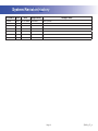
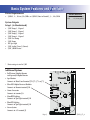
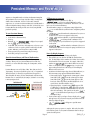
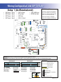
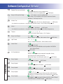
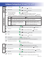
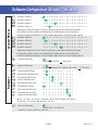
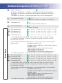
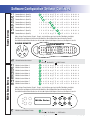
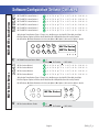
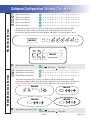
MS8500E Mach 3 Hot Sheet
Master Spas
System PN 55862
System Model # GL8-MS8500E-RCA-3.0K
Software Version # 30
EPN # 2615
Base PCBA – PN 55863
PCB GL8000 – PN 22960 Rev B or C
HEX File – 10013930_MS8500E
Configuration Signature – E9FC010D
Base Panels
MP700 – PN 53251-01
Aux Panels
AX10 (Jets 1) – PN 52803
AX10 (Jets 2) – PN 52804
AX10 (Jets 4) – PN 52806
Template used: 40598-v29-30_D.pdf 07/19/2007
55862_97_A.pdf 01/02/2008
Page 1
55862_97_A
System Revision History
System PN EPN
55862
Date
Requested By
2615 01.02.2008 Customer
Changes Made
New system
Page 2
55862_97_A
Basic System Features and Functions
Power Requirements
Internal Reference
53859-04. . . GL8000 Base System
25093 . . . . . PS-34 Pump Splitter
s 6!#^!OR!(ZOR6!#,INETO.EUTRAL^!(Z
System Outputs
Setup 1 (As Manufactured)
s
s
s
s
s
s
s
s
s
60UMP3PEED
60UMP3PEED
60UMP3PEED
60UMP3PEED
6#IRC0UMP
6/ZONE
63PA,IGHT
6Audio\Visual (Stereo)
6K7(EATER
(EATERWATTAGEISRATEDAT6
1
2
3
3
J38
s &ULL&EATURE$OLPHIN2EMOTE
AND3PAONLY$OLPHIN2EMOTE
2
J33
Additional Options
1
J37
J16
W1
J14
F4 F3A 250V
J10
2
J34
J77
1
s )2OR2&$OLPHIN2ECEIVER-ODULES
#ONNECTSTO2EMOTETERMINAL*
G
F4
J40
J16
s 3PA-ONITOR
#ONNECTSTO-AIN0ANELTERMINAL***OR*
3
AUX PANELS
N
W2
J52
G
N
G
J70
N
J31
J7
s /ZONE'ENERATOR
#ONNECTSTOTERMINAL*
MAIN PANELS
J71
J13
J30
J8
s -OOD%&8,IGHTING
#ONNECTSTO3PA,IGHTTERMINAL*
J84
J46
3
J72
2
J73
1
EXT I/O
s &IBER%&8,IGHTING
#ONNECTSTO3PA,IGHTTERMINAL*
J91
J69
TV2
CHBANK B
Page 3
SEN. A
SEN. B
VAC
REMOTE
J17
J83
J19
J82
J24
J22
J18
ADCM
J15
J21
RLY
J51
s 3TEREO3YSTEM
#ONNECTSTO!6TERMINAL*
J20
J36
UV
TV1
TST
AUX. F
CFG
55862_97_A
Persistent Memory and Powering Up
Any time you change DIP Switches or Software Configuration Settings that
affect parameters the user can change (any filter settings, set temperature
default, Celsius vs Fahrenheit, 12-hour vs 24-hour time, reminders
suppression, etc), you must reset Persistent Memory for your DIP Switch or
Software Configuration Settings changes to take effect. You should also reset
Persistent Memory after loading a new file into a board (using the ESM,
purchased seperately).
To reset Persistent Memory:
s Power down.
s Set A12 ON (See illustration below).
s Power up.
s Wait until “ ” or “
” is displayed on your panel.
” appears see section below.
Note: If “
s Set A12 OFF. (This can be done safely with power on if you use a nonconductive tool such as a pencil to push the switch back to the OFF
position. Otherwise, power down before setting A12 OFF)
s Power up again (if you powered down in the previous step).
s For all other power ups, leave A12 OFF.
About Persistent Memory and Time of Day Retention:
This system uses memory that doesn’t require a battery to store a variety
of settings. What we refer to as Persistent Memory stores all the User
Preferences, as well as all the filter settings, the set temperature, and the
heat mode.
Persistent Memory is not used for Time of Day. Time of Day needs to be
“kept running” (not just stored) while the power is off, so a separate Real
Time Clock feature (on all models except the EL1000) keeps track of
Time of Day while the unit is off. Time of Day Retention, and Time of Day
Retention alone, is controlled by the J91 jumper. J91 must be set according
to main system panel used.
Switchbank A
J91
RTC
Enabled
(Not Jumpered)
Switchbank B
J91
RTC
Disabled
(Jumpered)
message on power up:
If “
” appears before (and instead of) “ ” or
”, you have not configured DIP Switches and/or
“
Software Configuration Settings in a valid manner. This must be corrected
before you can reset Persistent Memory.
The switch numbers, jumpers, or configuration settings displayed after
“
” are ones with which the system has found a configuration problem.
For example:
s “
” would mean that the combination of how you’ve set
A5 and how you’ve set B2 is not supported on this system.
s “
” would mean that there is a problem with jumper J99
s “
” would mean that the combination of how
you’ve set pump 3 for 1-speed and blower for 1-speed is not supported
on this system.
s “
” would mean that the combination of how you’ve
set DIP switches which have been assigned to pump 3 and blower is not
supported on this system.
Power Up Display Sequence
Upon power up, you should see the following on the display:
s Three numbers in a row, which are the SSID (the System Software
ID). The third display of these numbers is the Software Version, which
should match the version of your system. For example, if these three
, that is a Mach 3 EL8000 at version 26.
numbers are
s If there is a Configuration Error, the
message (see above) will
appear at this point (and none of the messages below will display).
Otherwise what comes next is:
s An indication of either the input voltage detected (EL1000/EL2000), or
the heater wattage range supported (EL8000/GL2000/GL8000).
s Heater wattage display: “ ” means the system supports a heater
” means the system supports a heater
from 1 kW to 3 kW. “
” means the system supports a 3 kW
from 3 kW to 6 kW. “
heater only. (These ranges may be modified slightly in the case of
special heaters, which the next bullet covers.)
s Input voltage display: A system showing “
” supports 3 kW
to 6 kW heaters. A system showing “ ” supports the very same
heaters, although at 120V those heaters will function at only 1/4 of
” or
their 240V rated wattage. (The system shows only either “
” as a general indication of input voltage; it does not show the
“
actual input voltage.)
s If your system is using a special type of heater, a display such as “ ”
may appear next. If your system is using the generic Balboa heater, no
heater type display will appear.
s “ ” or “
” will appear to signal the start of
Priming Mode.
At this point, the power up sequence is complete. Refer to the User Guide
for the ML Series panel on your system for information about how the spa
operates from this point on.
Page 4
55862_97_A
Wiring Configuration and DIP Settings
HIPot Testing Note:
Setup 1 (As Manufactured)
6#IRC0UMP
63PA,IGHT
6/ZONE
6!<6(Stereo)
J2
J74
3
2
J75
J76
K1
J60
1
J11
2
1
J38
3
2
1
J37
G
N
PS-34
A.
N V.
W1
J14
W2
J16
Spa
Light
N
G
F7
J12
G
N
2-Spd
P2
K2
3
J16
J5
P/N 22960_C
2
F4
G
MADE IN U.S.A.
F7, T30A 480V
3
J50
J10
K5
J53
1
2
J96
3
J52
J47
J7
F2, T 0.5A 250V
J95
J34
J77
J54
1
F2
2
3
N
G
N
G
J31
J94
F6, T30A 480V
J70
J27
BARCODE
K3
F6
J40
F4, F3A 250V
J79
TB1
J13
J30
3
2
M11
J25
J26
J84
1
J46
K13
1
2
3
J72
J28
3
J8
2
J93
MAIN PANELS
J49
J32
J71
1
J23
F9
F1
J21
ADCM
J18
SWITCHBANK A
SWITCHBANK B
SEN. A
SEN. B
VAC
UV
TV1
Pump 3
To J12
TST
AUX. F
J83
CFG
Configuration
Settings
Enabled
Red
White
REMOTE
J17
J19
3.0 kW
J90
J82
K8
J24
HTR1
J22
HTR2
RTC
Enabled
J20
J51
RLY
J69
J57
J58
J91
J36
TV2
J15
F9, T30A 480V
K6
J59
EXT I/O
J73
M1
4
K7
10 VAC-B 10 VAC-A
N
K15
G
G
K10
BALBOA INSTRUMENTS, INC.
GL8000 Mach 3
COPYRIGHT 2006
1
J62
J6
G
N
N
2-Spd P1
K11
J9
F5
F5, F10A 250V
Ozone
K4
J29
J56
J55
J4
K9
Circ Pump
J1
J14
AUX PANELS
J3
N
3
G
J39
2
J33 J41 J81 J45
1
Reconnect terminal to J90 after
successful completion of HiPot test.
N
Balboa
Disconnect slip terminal with green
wires from J90 prior to performing
HiPot test. Failure to disconnect will
cause a false failure of the test.
s 6K7(EATER
s -0-AIN0ANEL
G
s
s
s
s
N
60UMP3PEED
60UMP3PEED
60UMP3PEED
60UMP3PEED
G
s
s
s
s
White
PS-34
PN 25093
Pump 4
Green
Black
Green
WARNING: Main Power to system should be turned OFF BEFORE adjusting DIP switches.
WARNING: Persistent Memory (A12) must be RESET to allow new DIP switch settings to take effect. (See Persistent Memory page)
Switchbank A
Wiring Color Key
Switchbank B
Neutral (Common) AC Connections
SSID #
Special AC Connections
100
139
30
A3, + 2 Pumps w/Heat
A7, Not
Assignable
Assigned
A8, Not
Assignable
Assigned
A9, Not
Assignable
Assigned
A5, Not
Assignable
Assigned
A6, Not
Assignable
Assigned
A11, Special Amp Rule OFF
A12, Memory ON
B1, Not
Assignable
Assigned
B2, Not
Assignable
Assigned
B3, Not
Assignable
Assigned
B4, Not
Assignable
Assigned
B5, Not
Assignable
Assigned
B6, Not
Assignable
Assigned
B7, Not
Assignable
Assigned
B8, Not
Assignable
Assigned
B9, Not
Assignable
Assigned
B10, Not
Assignable
Assigned
B11, Not
Assignable
Assigned
B12, Not
Assignable
Assigned
RTC
Enabled
J91
Page 5
Line AC Connections
10 Volt Connections
Relay Control Wires
Board Connector Key
Config Settings
Enabled
J83
1
Typically Line voltage
2
Typically Line voltage for 2-speed pumps
3
Neutral (Common)
4
Ground
Note flat sides in connector
55862_97_A
DIP Switches and Jumper Definitions
WARNING:
sSetting DIP switches incorrectly may cause abnormal system behavior and/or damage to system components.
sRefer to Switchbank illustration on Wiring Configuration page for correct settings for this system.
sContact Balboa if you require additional configuration pages added to this hot sheet.
DIP Switchbank A Key
A1
............... Test Mode (normally Off)
A2
............... In “ON” position, add one high-speed pump (or blower) with Heater
A3
............... In “ON” position, add two high-speed pumps (or 1 HS Pump and Blower) with Heater
A4
............... In “ON” position, add four high-speed pumps (or 3 HS Pumps and Blower) with Heater
A10 ............... When switched ON when spa is on, system will enter the Edit Menu for Configuration Settings
Do not start spa with A10 turned on or CFE* error will occur
A11 ............... In “ON” position, enables Special Amperage Rule, see "SA" in Software Configuration section for functionality with your system
............... In “OFF” position, disables Special Amperage Rule
A12 ............... Persistent memory reset (used when spa is powering up) See "Persistent Memory and Powering Up" page
A2, A3, and A4 work in combination to determine the number of high-speed devices and blowers that can run before the heat is disabled. i.e.
A2 and A3 in the ON position and A4 in the OFF position will allow the heater to operate with up to 3 high-speed pumps (or two HS Pumps and
Blower) running at the same time. Heat is disabled when the fourth high-speed pump or blower is turned on.
Note: A2/A3/A4 all off = No heat with any high-speed pump or blower.
*CFE errors are illegal configurations such as a pump and a blower set to run on the same output. The configuration must be corrected before
the spa will operate.
Assignable DIP Switch Key
A5
. . . . . . Not Assigned
A6
. . . . . . Not Assigned
A7
. . . . . . Not Assigned
A8
. . . . . . Not Assigned
A9
. . . . . . Not Assigned
B1
. . . . . . Not Assigned
B2
. . . . . . Not Assigned
B3
. . . . . . Not Assigned
B4
. . . . . . Not Assigned
B5
. . . . . . Not Assigned
B6
. . . . . . Not Assigned
B7
. . . . . . Not Assigned
B8
. . . . . . Not Assigned
B9
. . . . . . Not Assigned
B10 . . . . . . Not Assigned
B11 . . . . . . Not Assigned
B12 . . . . . . Not Assigned
Jumpers Key
J91 . . . . . . . . . Jumper on 1 Pin only enables Real Time Clock function, for use with time capable panels.
Jumper on Pins 1 and 2 will disable RTC function, for use with non-time capable panels.
Page 6
55862_97_A
Electrical Service Configuration Options
F
For Software Configured System
Single Service (1 x 16 Amp or 1 x 32 Amp)
F2 T 0.5A 250V
J95
F2
This option is configured and shipped as the default.
For 1 x 32 Amp Service:
DIP Switch A2, A3, and A4 can be ON
For 1 x 16 Amp Service:
DIP Switch A2, A3, and A4 must be OFF
For 1 x 16 Amp and 1 x 32 Amp Service:
DIP Switch A11 must be ON if using Special Amperage Rule
DIP Switch A11 must be OFF if not using Special Amperage Rule
TB1
1
J23
J32
2
J28
L1
3
N1
4
M11
J26
M1
K7
K6
J59
J57
J58
HTR2
HTR1
F
K8
Dual Service Option (2 x 16 Amp)
F2 T 0.5A 250V
J95
F2
TB1
L2
1
N2
2
L1
3
N1
4
J23
J28
J32
Note: J32 and J23 are electrically identical. The white
wire may be attached to either terminal before removal.
M11
DIP Switch A2, A3, and A4 must be ON
DIP Switch A11 must be ON if using Special Amperage Rule
DIP Switch A11 must be OFF if not using Special Amperage Rule
J26
M1
K7
Completely remove the white wire from J26 and J32.
K6
J59
J57
J58
HTR2
HTR1
K8
3-Phase Service Option
F
IMPORTANT - Service MUST include a neutral wire,
with a line to neutral voltage of 230VAC.
Completely remove the white wire from J26 and J32.
F2 T 0.5A 250V
J95
F2
TB1
L3
1
L2
2
L1
3
N
4
J23
J28
Note: J32 and J23 are electrically identical. The white
wire may be attached to either of these terminals
before removal.
J32
M11
Completely remove the blue wire from J28 and J57.
J26
Note: J57, J58 and J59 are electrically identical. The blue
wire may be attached to any of these terminals before
removal.
M1
K7
K6
J59
Move the brown wire from J23 or J32 to J28.
J57
J58
HTR2
HTR1
K8
DIP Switch A2, A3, and A4 must be ON
DIP Switch A11 must be OFF
Page 7
55862_97_A
Software Configuration Settings
Program Filter Cycles by Duration
n Y
n = Start and stop times; for time capable panels.
Y = Duration; for non-time capable panels
= 1 DIP Switch
Pump 1 in Filter (w/Circ Pump)
n Y (This feature is used in Circ Mode only.)
Allows Pump 1 Low to operate in Filter Cycles to add extra filtration.
n = Normal; Y = Pump 1 with Circ
24-Hour Time *
n Y
n = 12-hour (am/pm); Y = 24-hour (military\European);
= 1 DIP Switch
* Sets default for user preferences - only applies when persistent memory is reset (A12 On) during power-up.
Celsius *
n Y
n = Fahrenheit; Y = Celsius;
= 1 DIP Switch
* Sets default for user preferences - only applies when persistent memory is reset (A12 On) during power-up
Timeouts
1 F 2 3 4 5 6
1-6 = 10, 20, 30, 40, 50, 60 minutes; F = 15 minutes
Pump 1 Low Timeout
d 1 2 3 4
d = Use “Timeouts” value above; 1-4 = number of hours;
Light Timeout
d 1 2 3 4
d = Use “Timeouts” value above; 1-4 = number of hours
Scrunch Panel
n Y
n = Normal panel layout;
Y = Alternate panel layout (ML900 scrunching enabled - ML550/700
Jets 3 replaces Blower;
= 1 DIP Switch
Circ Type (behavior)
n A 3 P
n = Non circ or circ pump not plumbed with heater; A = 24-hour;
3 = 24-hour with 3ºF shutoff outside filter;
P = Acts like Pump 1 Low (filter cycles, polls, etc.);
= 2 DIP Switch
Pump 1 Speeds
1 2
1 = 1 speed; 2 = 2 speed;
Pump 2 Speeds
PUMP SPEEDS
= 3 DIP Switch
Pump 3 Speeds
Pump 4 Speeds
Pump 5 Speeds
= 1 DIP Switch
0 1 2
0 = Disabled; 1 = On/Off; 2 = 2 speed;
= 2 DIP Switch
0 1 2
0 = Disabled; 1 = On/Off; 2 = 2 speed;
= 3 DIP Switch
0 1 E H L
0 = Disabled; 1 = On/Off on board; E = External X-P CE or X-P231 CE board
H = On/Off on pin 1 of X-P632 CE board; L = 2 speed on X-P632 CE board; = 3 DIP Switch
0 1 E L
0 = Disabled; 1 = On/Off on board; E = External X-P CE or X-P231 CE board
L = On/Off on pin 2 of X-P632 CE board; = 2 DIP Switch
Page 8
55862_97_A
PUMP SPEEDS
Software Configuration Settings Continued
Pump 6 Speeds
Blower Speeds
0 1
0 = Disabled; 1 = On/Off;
0 1
0 = Disabled; 1 = On/Off;
= 1 DIP Switch
= 2 DIP Switch
LIGHTING CONTROL
Separate Spa Light Buttons
n Y
See Chart Below
(This feature applies when
n = No Spa light button, Spa Light output is on with Fiber;
using Fiber Optic light)
Y = Separate Spa Light button on ML900 or Aux panel; = 1 DIP Switch
Note: The Light button on an ML900 panel is a SpaLight button. The Light button on most other panels is an EitherLight button.
Fo.n
Fo.Y
Lb.n
Lb.Y
No separately-controlled fiber light; spa light enabled on both SpaLight and EitherLight
buttons; fiber light (not wheel) comes on with spa light (at any intensity)
No separately-controlled fiber light; fiber
Spa light and fiber light each separately
light enabled on both FiberLight and
controlled; fiber light enabled on both
EitherLight buttons; spa light comes on
FiberLight and EitherLight buttons; spa light
with fiber light
enabled on SpaLight buttons only
Spa Light On/Off
Fiber Optics
Option
Mister
Cleanup Cycles *
n Y
n = Dimmable (H, M, L) Light; Y = On/Off Light;
n Y
n = Disabled; Y = Light and Wheel Enabled;;
n Y
n = Disabled; Y = Enabled;
= 1 DIP Switch
n Y
n = Disabled; Y = Enabled;
= 1 DIP Switch
= 1 DIP Switch
= 2 DIP Switch
0 1 2 3 4
0 = Disabled; 1-4 = Number of hours
OZONE
* Sets default for user preferences - only applies when persistent memory is reset (A12 On) during power-up.
Cleanup Cycles as User Preference
n Y
n = Only in Configuration Settings;
Y = Over-rideable by User via User Preferences
Ozone Operation
A F
A= Operates with Heater Pump (Pump 1 Low or Circ Pump);
F = Operates in Filter and Cleanup Cycles only;
= 1 DIP Switch
Ozone Suppression
n Y
n = No Suppress; Y = 1-hour suppress on button press;
= 1 DIP Switch
Ozone Icon
n Y U
n = Disabled; Y = Enabled ; U = Controlled by UV input
Option Qualify
n Y
n = Option button Normal; Y = Option button qualified by UV input
Page 9
55862_97_A
AUXILIARY BUTTONS
Software Configuration Settings Continued
Aux Button 1 (Bank A)
1 2 3 4 5 6 b g F E o t d P n A U r O H 9 L 8
Aux Button 2 (Bank A)
1 2 3 4 5 6 b g F E o t d P n A U r O H 9 L 8
Aux Button 3 (Bank A)
1 2 3 4 5 6 b g F E o t d P n A U r O H 9 L 8
Aux Button 4 (Bank A)
1 2 3 4 5 6 b g F E o t d P n A U r O H 9 L 8
1-6 = Assigns Pump Number (Pump 1, Pump 2, etc); b = Blower; g = Spa Light; F = Fiber-Optic wheel/light;
E = EitherLight; o = Option; t = Mister; d = CK Mode/Cool; P = CK Option/Heat; n = CK Intensity/TurboHt;
A = ACD Aroma; U = Button Disabled; r = Air Valve; O = Option 2; H = Option 3; 9 = Invert; L = Option 4; 8 = Stir
Aux Button 1 (Bank B)
1 2 3 4 5 6 b g F E o t d P n A U r O H 9 L 8
Aux Button 2 (Bank B)
1 2 3 4 5 6 b g F E o t d P n A U r O H 9 L 8
Aux Button 3 (Bank B)
1 2 3 4 5 6 b g F E o t d P n A U r O H 9 L 8
Aux Button 4 (Bank B)
1 2 3 4 5 6 b g F E o t d P n A U r O H 9 L 8
1-6 = Assigns Pump Number (Pump 1, Pump 2, etc); b = Blower; g = Spa Light; F = Fiber-Optic wheel/light;
E = EitherLight; o = Option; t = Mister; d = CK Mode/Cool; P = CK Option/Heat; n = CK Intensity/TurboHt;
A = ACD Aroma; U = Button Disabled; r = Air Valve; O = Option 2; H = Option 3; 9 = Invert; L = Option 4; 8 = Stir
Aux Button Bank Select
REMINDERS
Suppress all Reminders
A b
A = Bank A; b = Bank B;
= 1 DIP Switch
n Y
n = Display Reminders; Y = Suppress all Reminders;
Check pH Reminder Period
0
1
2
3
4
5
6
7
8
9
t
Check Sanitizer Reminder Period
0
1
2
3
4
5
6
7
8
9
t
Clean Filter Reminder Period
0
1
2
3
4
5
6
7
8
9
t
Test GFCI Reminder Period
0
1
2
3
4
5
6
7
8
9
t
Drain Water Reminder Period
0
1
2
3
4
5
6
7
8
9
t
Change Mineral Cartridge
0
1
2
3
4
5
6
7
8
9
t
Clean Cover Reminder Period
0
1
2
3
4
5
6
7
8
9
t
Treat Wood Reminder Period
0
1
2
3
4
5
6
7
8
9
t
Change Filter Reminder Period
0
1
2
3
4
5
6
7
8
9
t
= 1 DIP Switch
0 = Off; 1 = 7 days; 2 = 14 days; 3 = 30 days; 4 = 45 days; 5 = 60 days; 6 = 90 days;
7 = 120 days; 8 = 180 days; 9 = 365 days; t = 21 days
Lowest Set Temperature *
8 7
8 = 80˚F/26.0˚C; 7 = 70˚F/21.0˚C
* Setting LS at 7 and Fr at 5 will cause a CFE error.
Page 10
55862_97_A
Software Configuration Settings Continued
Default Set Temperature *
5
6
7
8
9
0
1
2
3
4
E
F
n
5 = 95˚F/35.0˚C; 6 = 96˚F/35.5˚C; 7 = 97˚F/36.0˚C; 8 = 98˚F/36.5˚C; 9 = 99˚F/37.0˚C; 0 = 100˚F/38.0˚C;
1 = 101˚F/38.5˚C; 2 = 102˚F/39.0˚C; 3 = 103˚F/39.5˚C; 4 = 104˚F/40.0˚C; E = 80˚F/26.5˚C; F = 85˚F/29.5˚C
n = 90˚F/32.0˚C
* Sets default for user preferences - only applies when persistent memory is reset (A12 On) during power-up.
Freeze Temperature Threshold
3 4 9 5
3 = 39˚F/3.9˚C; 4 = 44˚F/6.7˚C; 9 = 49˚F/9.4˚C;
5 = 54˚F/12.2˚C;
Set Temperature Lock
t
S
t = Temp Lock Only; S = Temp + Settings Lock
Light Cycle Programming
n Y
n = Disabled; Y = Enabled
Filter 1 Start Hour (Set 1) *
- 0 1 2 3 4 5 6 7 8 9 A b C d E F g H J L n o P r
Filter 1 Duration (Set 1) *
- 0 1 2 3 4 5 6 7 8 9 A b C d E F g H J L n o P r
Filter 2 Start Hour (Set 1) *
- 0 1 2 3 4 5 6 7 8 9 A b C d E F g H J L n o P r
Filter 2 Duration (Set 1) *
- 0 1 2 3 4 5 6 7 8 9 A b C d E F g H J L n o P r
- = Standard Defaults; 0 = 0 (12 am, 24); 1-9 = 1-9; A = 10; b = 11; C = 12; d = 13 (1 pm); E = 14 (2 pm);
F = 15 (3 pm); g = 16 (4 pm); H = 17 (5 pm); J = 18 (6 pm); L = 19 (7 pm); n = 20 (8 pm); o = 21 (9 pm);
P = 22 (10 pm); r = 23 (11 pm)
FILTER CYCLES
These settings allow customization of the filter defaults. If any of these four settings is "-", the standard filter
defaults are used.
1d and 2d cannot both be set to 0.
When Fd.n is selected, 1d and 2d are Filter 1 and Filter 2 Duration specifically.
When Fd.y is selected:
If 1d is set to 0, 2d is the duration; otherwise 1d is the duration.
If 1d is set to 0, only the Night cycle runs.
If 2d is set to 0, only the Day cycle runs.
If neither 1d nor 2d is set to 0, both the Day and Night cycles run.
* Sets default for user preferences - only applies when persistent memory is reset (A12 On) during power-up.
Filter 1 Start Hour (Set 2) *
- 0 1 2 3 4 5 6 7 8 9 A b C d E F g H J L n o P r
Filter 1 Duration (Set 2) *
- 0 1 2 3 4 5 6 7 8 9 A b C d E F g H J L n o P r
Filter 2 Start Hour (Set 2) *
- 0 1 2 3 4 5 6 7 8 9 A b C d E F g H J L n o P r
Filter 2 Duration (Set 2) *
- 0 1 2 3 4 5 6 7 8 9 A b C d E F g H J L n o P r
- = Standard Defaults; 0 = 0 (12 am, 24); 1-9 = 1-9; A = 10; b = 11; C = 12; d = 13 (1 pm); E = 14 (2 pm);
F = 15 (3 pm); g = 16 (4 pm); H = 17 (5 pm); J = 18 (6 pm); L = 19 (7 pm); n = 20 (8 pm); o = 21 (9 pm);
P = 22 (10 pm); r = 23 (11 pm)
These settings allow customization of the filter defaults. If any of these four settings is "-", the standard filter
defaults are used.
3d and 4d cannot both be set to 0.
When Fd.n is selected, 3d and 4d are Filter 1 and Filter 2 Duration specifically.
When Fd.y is selected:
If 3d is set to 0, 4d is the duration; otherwise 3d is the duration.
If 3d is set to 0, only the Night cycle runs.
If 4d is set to 0, only the Day cycle runs.
If neither 3d nor 4d is set to 0, both the Day and Night cycles run.
* Sets default for user preferences - only applies when persistent memory is reset (A12 On) during power-up.
Page 11
55862_97_A
Filter Default Start Time Set *
= 1 DIP Switch
* Sets default for user preferences - only applies when persistent memory is reset (A12 On) during power-up.
Filter Default Duration Set *
1 2
1 = Set 1; 2 = Set 2;
= 1 DIP Switch
* Sets default for user preferences - only applies when persistent memory is reset (A12 On) during power-up.
Pump Purge Duration
3 1 2 5 t
3 = 30 seconds; 1 - 5 = 1 - 5 minutes; t = 10 minutes
Blower Purge Duration
5 1 2 3 4 6 t F
5 = 5 seconds; 1 = 10 seconds; 2 = 20 seconds; 3 = 30 seconds;
4 = 45 seconds; 6 = 60 seconds (1 minute); t = 2 minutes; F = 5 minutes
Mister Purge Duration
5 1 2 3 4 6 t F
5 = 5 seconds; 1 = 10 seconds; 2 = 20 seconds; 3 = 30 seconds;
4 = 45 seconds; 6 = 60 seconds (1 minute); t = 2 minutes; F = 5 minutes
Air Valve
n Y
n = Disabled; Y = Enabled on "alarm" relay
Option 2
n Y
n = Disabled; Y = Enabled on "alarm" relay;
Option 3
Option 4
= 1 DIP Switch
n Y
n = Disabled; Y = Enabled on pin 1 of X-P632 board;
= 1 DIP Switch
n Y
n = Disabled; Y = Enabled on pin 2 of X-P632 board;
= 1 DIP Switch
Remote Button 1 (Bank A)
1 2 3 4 5 6 b g F E o t d P n A U r O H 9 L 8
Remote Button 2 (Bank A)
1 2 3 4 5 6 b g F E o t d P n A U r O H 9 L 8
Remote Button 3 (Bank A)
1 2 3 4 5 6 b g F E o t d P n A U r O H 9 L 8
Remote Button 4 (Bank A)
1 2 3 4 5 6 b g F E o t d P n A U r O H 9 L 8
Remote Button 5 (Bank A)
1 2 3 4 5 6 b g F E o t d P n A U r O H 9 L 8
Remote Button 6 (Bank A)
1 2 3 4 5 6 b g F E o t d P n A U r O H 9 L 8
Remote Button 7 (Bank A)
1 2 3 4 5 6 b g F E o t d P n A U r O H 9 L 8
Remote Button 8 (Bank A)
1 2 3 4 5 6 b g F E o t d P n A U r O H 9 L 8
1-6 = Assigns Pump Number (Pump 1, Pump 2, etc); b = Blower; g = Spa Light; F = Fiber-Optic wheel/light;
E = EitherLight; o = Option; t = Mister; d = CK Mode/Cool; P = CK Option/Heat; n = CK Intensity/TurboHt;
A = ACD Aroma; U = Button Disabled; r = Air Valve; O = Option 2; H = Option 3; 9 = Invert; L = Option 4; 8 = Stir
2
8
3
7
1
6
5
DOLPHIN REMOTE
2
ROUND REMOTE
4
REMOTE BUTTONS
1 2
1 = Set 1; 2 = Set 2;
1
PURGE DURATION
FILTER CYCLES
Software Configuration Settings Continued
4
5
Page 12
55862_97_A
Remote Button 1 (Bank B)
1 2 3 4 5 6 b g F E o t d P n A U r O H 9 L 8
Remote Button 2 (Bank B)
1 2 3 4 5 6 b g F E o t d P n A U r O H 9 L 8
Remote Button 3 (Bank B)
1 2 3 4 5 6 b g F E o t d P n A U r O H 9 L 8
Remote Button 4 (Bank B)
1 2 3 4 5 6 b g F E o t d P n A U r O H 9 L 8
Remote Button 5 (Bank B)
1 2 3 4 5 6 b g F E o t d P n A U r O H 9 L 8
Remote Button 6 (Bank B)
1 2 3 4 5 6 b g F E o t d P n A U r O H 9 L 8
Remote Button 7 (Bank B)
1 2 3 4 5 6 b g F E o t d P n A U r O H 9 L 8
Remote Button 8 (Bank B)
1 2 3 4 5 6 b g F E o t d P n A U r O H 9 L 8
1-6 = Assigns Pump Number (Pump 1, Pump 2, etc); b = Blower; g = Spa Light; F = Fiber-Optic wheel/light;
E = EitherLight; o = Option; t = Mister; d = CK Mode/Cool; P = CK Option/Heat; n = CK Intensity/TurboHt;
A = ACD Aroma; U = Button Disabled; r = Air Valve; O = Option 2; H = Option 3; 9 = Invert; L = Option 4; 8 = Stir
8
3
7
2
4
1
6
5
DOLPHIN REMOTE
2
ROUND REMOTE
1
REMOTE BUTTONS
Software Configuration Settings Continued
4
5
ML90X SERIES BUTTONS
Remote Button Bank Select
A b
A = Bank A; b = Bank B;
= 1 DIP Switch
ML90x Custom Button 1
1 2 3 4 5 6 b g F E o t d P n A U r O H 9 L 8
ML90x Custom Button 2
1 2 3 4 5 6 b g F E o t d P n A U r O H 9 L 8
ML90x Custom Button 3
1 2 3 4 5 6 b g F E o t d P n A U r O H 9 L 8
ML90x Custom Button 4
1 2 3 4 5 6 b g F E o t d P n A U r O H 9 L 8
ML90x Custom Button 5
1 2 3 4 5 6 b g F E o t d P n A U r O H 9 L 8
ML90x Custom Button 6
1 2 3 4 5 6 b g F E o t d P n A U r O H 9 L 8
ML90x Custom Button 7
1 2 3 4 5 6 b g F E o t d P n A U r O H 9 L 8
ML90x Custom Button 8
1 2 3 4 5 6 b g F E o t d P n A U r O H 9 L 8
1-6 = Assigns Pump Number (Pump 1, Pump 2, etc); b = Blower; g = Spa Light; F = Fiber-Optic wheel/light;
E = EitherLight; o = Option; t = Mister; d = CK Mode/Cool; P = CK Option/Heat; n = CK Intensity/TurboHt;
A = ACD Aroma; U = Button Disabled; r = Air Valve; O = Option 2; H = Option 3; 9 = Invert; L = Option 4; 8 = Stir
1
2
3
4
8
7
6
5
ML90x Series
ML90x Custom Buttons Enable
n Y
n = Disabled; Y = Enabled;
Page 13
= 1 DIP Switch
55862_97_A
ML75X/MX75X SERIES BUTTONS
Software Configuration Settings Continued
ML75x/MX75x Custom Button 1
1 2 3 4 5 6 b g F E o t d P n A U r O H 9 L 8
ML75x/MX75x Custom Button 2
1 2 3 4 5 6 b g F E o t d P n A U r O H 9 L 8
ML75x/MX75x Custom Button 3
1 2 3 4 5 6 b g F E o t d P n A U r O H 9 L 8
ML75x/MX75x Custom Button 4
1 2 3 4 5 6 b g F E o t d P n A U r O H 9 L 8
ML75x/MX75x Custom Button 5
1 2 3 4 5 6 b g F E o t d P n A U r O H 9 L 8
ML75x/MX75x Custom Button 6
1 2 3 4 5 6 b g F E o t d P n A U r O H 9 L 8
1-6 = Assigns Pump Number (Pump 1, Pump 2, etc); b = Blower; g = Spa Light; F = Fiber-Optic wheel/light;
E = EitherLight; o = Option; t = Mister; d = CK Mode/Cool; P = CK Option/Heat; n = CK Intensity/TurboHt;
A = ACD Aroma; U = Button Disabled; r = Air Valve; O = Option 2; H = Option 3; 9 = Invert; L = Option 4; 8 = Stir
ML70X SERIES BUTTONS
ML750/MX750 Custom Buttons Enable
6
5
4
1
2
3
ML75x Series
MX75x Series
n Y
n = Disabled; Y = Enabled;
= 1 DIP Switch
ML70x Custom Button 1
1 2 3 4 5 6 b g F E o t d P n A U r O H 9 L 8
ML70x Custom Button 2
1 2 3 4 5 6 b g F E o t d P n A U r O H 9 L 8
ML70x Custom Button 3
1 2 3 4 5 6 b g F E o t d P n A U r O H 9 L 8
ML70x Custom Button 4
1 2 3 4 5 6 b g F E o t d P n A U r O H 9 L 8
1-6 = Assigns Pump Number (Pump 1, Pump 2, etc); b = Blower; g = Spa Light; F = Fiber-Optic wheel/light;
E = EitherLight; o = Option; t = Mister; d = CK Mode/Cool; P = CK Option/Heat; n = CK Intensity/TurboHt;
A = ACD Aroma; U = Button Disabled; r = Air Valve; O = Option 2; H = Option 3; 9 = Invert; L = Option 4; 8 = Stir
4
3
1
2
ML70x Series
ML70x Custom Buttons Enable
n Y
n = Disabled; Y = Enabled;
Page 14
= 1 DIP Switch
55862_97_A
ML55X SERIES BUTTONS
Software Configuration Settings Continued
ML55x Custom Button 1
1 2 3 4 5 6 b g F E o t d P n A U r O H 9 L 8
ML55x Custom Button 2
1 2 3 4 5 6 b g F E o t d P n A U r O H 9 L 8
ML55x Custom Button 3
1 2 3 4 5 6 b g F E o t d P n A U r O H 9 L 8
ML55x Custom Button 4
1 2 3 4 5 6 b g F E o t d P n A U r O H 9 L 8
ML55x Custom Button 5
1 2 3 4 5 6 b g F E o t d P n A U r O H 9 L 8
1-6 = Assigns Pump Number (Pump 1, Pump 2, etc); b = Blower; g = Spa Light; F = Fiber-Optic wheel/light;
E = EitherLight; o = Option; t = Mister; d = CK Mode/Cool; P = CK Option/Heat; n = CK Intensity/TurboHt;
A = ACD Aroma; U = Button Disabled; r = Air Valve; O = Option 2; H = Option 3; 9 = Invert; L = Option 4; 8 = Stir
ML550
4
5
1
2
3
4
5
ML551
1
ML40X/ML2XX SERIES BUTTONS
ML55x Custom Buttons Enable
2
3
n Y
n = Disabled; Y = Enabled;
= 1 DIP Switch
ML40x/ML2xx Custom Button 1
1 2 3 4 5 6 b g F E o t d P n A U r O H 9 L 8
ML40x/ML2xx Custom Button 2
1 2 3 4 5 6 b g F E o t d P n A U r O H 9 L 8
ML40x/ML2xx Custom Button 3
1 2 3 4 5 6 b g F E o t d P n A U r O H 9 L 8
1-6 = Assigns Pump Number (Pump 1, Pump 2, etc); b = Blower; g = Spa Light; F = Fiber-Optic wheel/light;
E = EitherLight; o = Option; t = Mister; d = CK Mode/Cool; P = CK Option/Heat; n = CK Intensity/TurboHt; A = ACD Aroma;
U = Button Disabled (DO NOT USE); r = Air Valve; O = Option 2; H = Option 3; 9 = Invert; L = Option 4; 8 = Stir
ML400
1
ML200
2
3
ML40x/ML2xx Custom Buttons Enable
3
ML240
ML260
1 2
1 2
1 2
3
n Y
n = Disabled; Y = Enabled;
Page 15
3
= 1 DIP Switch
55862_97_A
Software Configuration Settings Continued
Special Amperage Rule *
1 2 3
1 = Blower off when 2nd high-speed pump on; 2 = Max 1 high-speed pump
3 = Max 2 high-speed pumps
* Note: DIP A11 must be ON to use Special Amperage Rule.
Heat Cool Feature
n Y
n = Disabled; Y = Enabled;
= 1 DIP Switch
Color Kinetics
n Y
n = Disabled; Y = Enabled
DR Mode
n Y
n = Disabled; Y = Enabled
Demo Mode
n Y
n = Disabled; Y = Enabled
Graphic Clock
n Y
n = Disabled; Y = Enabled (Panel must be able to support this feature)
Page 16
55862_97_A
Ozone Connections
Note: A special tool is required to remove the pins from the connector body once they are snapped in
place. Check with your Balboa Account Manager for information on purchasing a pin-removal tool.
Balboa Ozone connector configuration for 230VAC 50Hz:
L
Black or Brown Line Conductor
Empty
White or Blue Neutral Conductor
Empty
N
Flat sides of sockets as shown
Balboa
J2
J39
J4
K9
Line - Black or Brown conductor
Not used
Neutral - White or Blue conductor
Not used
3
2
G
G
K11
G
N
N
1
N
K4
J14
Circ Pump
J1
J3
BALBOA INSTRUMENTS, INC.
GL8000 Mach III
COPYRIGHT 2006
MADE IN U.S.A.
P/N 22960 REV B
J11
J5
N
V
G
A.
N V.
N
G
F7
J12
G
K2
Page 17
55862_97_A
Panel Configurations
TIME CAPABLE
Note: RTC jumper (J91) on Main PCBA must be OFF (1 pin only)
MP700
PN 53251-01 with No Overlay (Customer supplied)
s Connects to Main Panel terminal J70, J71, J72, or J73
AUXILIARY
Note: Connects to Aux Panel terminal J31, J34, J40, or J16
Blower
Jets 1
Blower
Jets 1
Blower
Jets 1
AX10 (Up to four can be used)
Jets 1 - PN 52803 with No Overlay (Customer supplied)
Jets 2 - PN 52804 with No Overlay (Customer supplied)
Jets 4 - PN 52806 with No Overlay (Customer supplied)
Page 18
55862_97_A