1
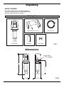
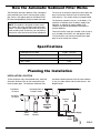
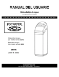
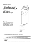
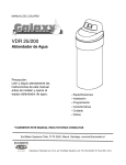
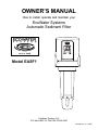
OWNER’S MANUAL
How to install, operate and maintain your
EcoWater Systems
Automatic Sediment Filter
Model EASF1
EcoWater Systems LLC
P.O. Box 64420, St. Paul, MN 55164-0420
7301805 (Rev. A 3/12/08)
Table of Contents
Before You Start . . . . . . . . . . . . . . . . . . . . . . . . . . . . . . . . . . . . . . . . . . . . . . . . . . . . . . . . . . . . . . . . . . . . . . . . . . . . 2
Warranty . . . . . . . . . . . . . . . . . . . . . . . . . . . . . . . . . . . . . . . . . . . . . . . . . . . . . . . . . . . . . . . . . . . . . . . . . . . . . . . . . . 3
Unpacking Dimensions . . . . . . . . . . . . . . . . . . . . . . . . . . . . . . . . . . . . . . . . . . . . . . . . . . . . . . . . . . . . . . . . . . . . .4
How the Automatic Sediment Filter Works . . . . . . . . . . . . . . . . . . . . . . . . . . . . . . . . . . . . . . . . . . . . . . . . . . . . . . . . .5
Specifications . . . . . . . . . . . . . . . . . . . . . . . . . . . . . . . . . . . . . . . . . . . . . . . . . . . . . . . . . . . . . . . . . . . . . . . . . . . . . . .5
Planning the Installation . . . . . . . . . . . . . . . . . . . . . . . . . . . . . . . . . . . . . . . . . . . . . . . . . . . . . . . . . . . . . . . . . . . . .5-6
Installation Location . . . . . . . . . . . . . . . . . . . . . . . . . . . . . . . . . . . . . . . . . . . . . . . . . . . . . . . . . . . . . . . . . . . . . . .5
Always Install the Filter Upright Reversing the Faceplate Mounting Bracket . . . . . . . . . . . . . . . . . . . . . .6
Installation Requirements . . . . . . . . . . . . . . . . . . . . . . . . . . . . . . . . . . . . . . . . . . . . . . . . . . . . . . . . . . . . . . . . . . . . . 7
Air Gap Requirements . . . . . . . . . . . . . . . . . . . . . . . . . . . . . . . . . . . . . . . . . . . . . . . . . . . . . . . . . . . . . . . . . . . . .7
Valve Drain Requirements . . . . . . . . . . . . . . . . . . . . . . . . . . . . . . . . . . . . . . . . . . . . . . . . . . . . . . . . . . . . . . . . . .7
Grounding Information . . . . . . . . . . . . . . . . . . . . . . . . . . . . . . . . . . . . . . . . . . . . . . . . . . . . . . . . . . . . . . . . . . . . .7
Installation Instructions . . . . . . . . . . . . . . . . . . . . . . . . . . . . . . . . . . . . . . . . . . . . . . . . . . . . . . . . . . . . . . . . . . . . 8-11
Installation Using Compression Fittings . . . . . . . . . . . . . . . . . . . . . . . . . . . . . . . . . . . . . . . . . . . . . . . . . . . . . 8-9
Installation Using Soldered Copper Fittings . . . . . . . . . . . . . . . . . . . . . . . . . . . . . . . . . . . . . . . . . . . . . . . . . 9-10
Installation Using Threaded Pipe & Fittings . . . . . . . . . . . . . . . . . . . . . . . . . . . . . . . . . . . . . . . . . . . . . . . . . . . 10
Install Drain Hose Check For Leaks Install Battery Optional AC Adaptor . . . . . . . . . . . . . . . . . . . . . 11
Programming the Electronic Controller . . . . . . . . . . . . . . . . . . . . . . . . . . . . . . . . . . . . . . . . . . . . . . . . . . . . . . . .12-13
Power Up Manually Start a Sediment Flush . . . . . . . . . . . . . . . . . . . . . . . . . . . . . . . . . . . . . . . . . . . . . . . . .12
Normal Operation LCD Backlight . . . . . . . . . . . . . . . . . . . . . . . . . . . . . . . . . . . . . . . . . . . . . . . . . . . . . . . . .12
Setting Number of Days Between Automatic Sediment Flushes . . . . . . . . . . . . . . . . . . . . . . . . . . . . . . . . . . . .13
Time of Day When Flush Occurs . . . . . . . . . . . . . . . . . . . . . . . . . . . . . . . . . . . . . . . . . . . . . . . . . . . . . . . . . . . .13
Low Battery Indication Battery Replacement . . . . . . . . . . . . . . . . . . . . . . . . . . . . . . . . . . . . . . . . . . . . . . . .13
Routine Maintenance . . . . . . . . . . . . . . . . . . . . . . . . . . . . . . . . . . . . . . . . . . . . . . . . . . . . . . . . . . . . . . . . . . . . . . . .14
Cleaning the Filter Screen . . . . . . . . . . . . . . . . . . . . . . . . . . . . . . . . . . . . . . . . . . . . . . . . . . . . . . . . . . . . . . . . .14
Troubleshooting Guide . . . . . . . . . . . . . . . . . . . . . . . . . . . . . . . . . . . . . . . . . . . . . . . . . . . . . . . . . . . . . . . . . . . . . . 15
Disassembly of Solenoid Disassembly of Valve . . . . . . . . . . . . . . . . . . . . . . . . . . . . . . . . . . . . . . . . . . . . . .15
Repair Parts . . . . . . . . . . . . . . . . . . . . . . . . . . . . . . . . . . . . . . . . . . . . . . . . . . . . . . . . . . . . . . . . . . . . . . . . . . . . . . 16
Before You Start
Read this entire manual before installing and using your Automatic Sediment Filter. Then, obtain all the materials
and tools you will need to make the installation. Follow all steps exactly and in order to correctly install.
The Automatic Sediment Filter must only be installed vertically, with the head up and the sump down. It will not
operate properly if installed horizontally or at an angle.
Check local plumbing, electrical and sanitation codes. You must follow their guides as you install the system.
Use only lead-free solder and flux for all sweat-solder connections, as required by federal codes.
Maximum operating pressure: 100 psi.
Maximum operating temperature: 120 °F.
Avoid installing in direct sunlight. Excessive sun heat may cause distortion or other damage to non-metallic parts.
For cold water use only. Do not install on a hot water line.
Do not use this system to treat water that is microbiologically unsafe or of unknown quality without adequate disinfection before or after the system.
Keep solvents and sprays away from the clear sump housing material. Surface cracking and failure can result.
European Directive 2002/96/EC requires all electrical and electronic equipment to be disposed of according to Waste Electrical and Electronic Equipment (WEEE) requirements. This directive or similar laws
are in place nationally and can vary from region to region. Please refer to your state and local laws for
proper disposal of this equipment.
In the state of Massachusetts: The Commonwealth of Massachusetts plumbing code 248-CMR shall
be adhered to. A licensed plumber shall be used for this installation.
Questions? Call Toll Free 1-800-86 WATER, Monday - Friday, 8 am - 8 pm CST.
2
Warranty
LIMITED WARRANTY
EcoWater Systems LLC
Advantage Warranty
Automatic Sediment Filter
Congratulations! You have just purchased the highest quality Automatic Sediment Filter on the market. To
register your warranty, complete the enclosed Warranty Registration Card and mail it within 30 days of purchase.
To whom is this warranty extended?
EcoWater Systems LLC warrants its products to the original owner and guarantees that the products, when
properly installed and maintained, will be free from defects in materials and workmanship from the original
date of installation.
How does my warranty work?
If, during the respective warranty period, a part proves, after inspection by EcoWater, to be defective,
EcoWater will, at its sole option, repair or replace that part at no charge, other than normal shipping, installation or service charges.
What is covered by the warranty?
EcoWater Systems LLC guarantees that, for a period of THREE YEARS, the Automatic Sediment Filter will
be free of defects in materials and workmanship and will perform its proper function.
How do I obtain warranty service?
Should you need service, your local, independent EcoWater Dealer is only a phone call away.
PHONE:____________________________________________________
To obtain warranty service, notice must be given, within thirty (30) days of the discovery of the defect, to your
local EcoWater Systems dealer.
General Provisions
The above warranties are effective provided the Automatic Sediment Filter is operated at water pressures
not exceeding 100 psi, and at water temperatures not exceeding 120°F; provided further that the Automatic
Sediment Filter is not subject to abuse, misuse, alteration, neglect, freezing, accident or negligence; and provided further that the Automatic Sediment Filter is not damaged as the result of any unusual force of nature
such as, but not limited to, flood, hurricane, tornado or earthquake. EcoWater Systems LLC is excused if failure to perform its warranty obligations is the result of strikes, government regulation, materials shortages, or
other circumstances beyond its control.
THERE ARE NO WARRANTIES ON THE AUTOMATIC SEDIMENT FILTER BEYOND THOSE SPECIFICALLY DESCRIBED ABOVE. ALL IMPLIED WARRANTIES, INCLUDING ANY IMPLIED WARRANTY OF
MERCHANTABILITY OR OF FITNESS FOR A PARTICULAR PURPOSE, ARE DISCLAIMED TO THE
EXTENT THEY MIGHT EXTEND BEYOND THE ABOVE PERIODS. THE SOLE OBLIGATION OF ECOWATER SYSTEMS LLC UNDER THESE WARRANTIES IS TO REPLACE OR REPAIR THE COMPONENT
OR PART WHICH PROVES TO BE DEFECTIVE WITHIN THE SPECIFIED TIME PERIOD, AND ECOWATER IS NOT LIABLE FOR CONSEQUENTIAL OR INCIDENTAL DAMAGES. NO ECOWATER DEALER,
AGENT, REPRESENTATIVE, OR OTHER PERSON IS AUTHORIZED TO EXTEND OR EXPAND THE
WARRANTIES EXPRESSLY DESCRIBED ABOVE.
Some states do not allow limitations on how long an implied warranty lasts or exclusions or limitations of incidental or consequential damage, so the limitations and exclusions in this warranty may not apply to you. This
warranty gives you specific legal rights, and you may have other rights which vary from state to state. This
warranty applies to consumer-owned installations only.
3
Unpacking
INSPECT SHIPMENT
The Automatic Sediment Filter is shipped complete in
one carton. Remove all items from the shipping carton
and check against the packing list below.
Packing List
Mounting Bracket & Screws
Filter Assembly
10 ft. Drain Hose
Hose Clamp
9V Battery
FIG. 1
Dimensions
Inlet & Outlet
1” NPT threaded
15"
10"
5-1/4"
4-1/8"
4
FIG. 2
How the Automatic Sediment Filter Works
The EcoWater Automatic Sediment Filter is designed
to be plumbed into a home’s incoming water supply
pipe, where it will capture particles of sediment from
the water and periodically flush them down the drain.
The unit has an electronic control that counts down the
days until the next automatic flush of collected sediment particles. The number of days is programmable.
The electronic controller runs on a 9 volt battery. The
controller will indicate when the battery needs to be
replaced. An optional AC power adaptor (P/N
7302835) may also be purchased to eliminate the
need for batteries.
NOTE: This product is designed to reduce sand,
grit, debris, pipe scale and other loose particulate
matter. On water supplies that contain sticky sediment including mud, silt and clay, you may have to
remove the sump and clean the screen periodically.
Three sizes of filter mesh are available. A 60 micron filter is included with the ASF unit, and optional 100 or
150 micron filters can also be purchased (see spare
parts list at the end of this manual).
Specifications
Rated Service Flow Rate
35 gpm (132 lpm)
Water Pressure Limits (minimum / maximum)
Water Temperature Limits (minimum / maximum)
Inlet - Outlet
30 - 100 psi (207 - 689 kPa)
40 - 120 °F (5 - 49 °C)
1” NPT
Planning the Installation
INSTALLATION LOCATION
To filter sediments from all household water, install the
Automatic Sediment Filter on the household’s main
incoming water pipe. The Automatic Sediment Filter
Cold Water
to House
should be installed upstream from the water softener
(if any), the water heater and all inside faucets. See
diagram below.
Untreated Water to
Outside Faucets
City Water Supply
Hot Water
to House
Pressure
Tank
OR
Automatic
Sediment
Filter
Water
Heater
Water
Softener
Well Water Supply
Well
Pump
FIG. 3
5
Planning the Installation
ALWAYS INSTALL THE FILTER UPRIGHT
To operate properly, the Automatic Sediment Filter
must be installed with the sump pointed straight down.
When possible, install the filter on a horizontal section
of the household’s main incoming water pipe. If the
available incoming main house water pipe runs vertically where you want to install the filter, buy 90° pipe
elbows and plumb a detour, as shown in Figure 4.
Allow enough space under the filter (6” minimum) to
remove the sump (to clean or replace the filter screen).
Allow enough space above the filter to remove the top
cover (to change batteries, etc.), as shown in Figure 4.
10”
10"
min.
min.
IN
OUT
House Water
Supply Pipe
Sump
Pointed
Straight
Down
REVERSING THE FACEPLATE / DISPLAY
The Automatic Sediment Filter must be installed with
the water flowing into the side of the filter marked IN.
Remove the unit’s top cover and observe the IN and
OUT markings. Depending on the direction of water
flow and the viewing angle, the faceplate may need to
be reversed (turned around to face the opposite direction) so that it does not end up against a wall or other
obstruction. This can be done either before or after
the filter is installed on the plumbing:
6”
min.
FIG. 4
Remove 2
screws and
turn faceplate
around, if
necessary
1. Remove the top cover from the ASF by sliding it
upward.
2. With a phillips screwdriver, remove the 2 screws
holding the faceplate assembly to the filter head
(See Figure 5).
3. Lift the faceplate assembly up and turn it around
180°, taking care not to pull on the wires between
the electronic control board and the valve solenoid.
4. Lower the faceplate assembly into place on the
opposite side of the head and reinstall the 2 screws.
5. Slide the top cover back onto the ASF and push it
down to snap into place.
FIG. 5
MOUNTING BRACKET
3"
A metal bracket is included with the Automatic
Sediment Filter to support the assembled filter and
plumbing when necessary. It may be mounted to a
wall or wall framing member with 2 screws (included),
as shown in Figure 6.
Mounting
Bracket
The 2 mounting bracket screws should be installed
before the filter is installed on the plumbing. When
installing the plumbing, be sure to put the bracket in
position around the ASF before installing inlet and outlet fittings. The bracket can not be put on after the
inlet and outlet fittings are installed.
FIG. 6
6
Installation Requirements
PLUMBING CODES
VALVE DRAIN REQUIREMENTS
All plumbing must be completed in accordance with
national, state and local plumbing codes.
Using the flexible drain hose (included), measure and
cut to the length needed.
Avoid drain hose runs longer than 10 feet. Make
the valve drain line as short and direct as possible.
In the state of Massachusetts: The Commonwealth
of Massachusetts plumbing code 248-CMR shall
be adhered to. A licensed plumber shall be used
for this installation.
If possible, avoid elevating the drain hose. This
could reduce the effectiveness of the flush cycle,
especially in a low pressure application.
The drain must be capable of handling a flow of 5 to
10 gallons per minute, depending on the home’s
water pressure.
AIR GAP REQUIREMENTS
The drain must be capable of handling the sediment
being flushed from the filter.
A drain is needed for sediment flush discharge water.
A floor drain, close to the Automatic Sediment Filter, is
preferred. A laundry tub, standpipe, etc. are other
drain options. The valve drain hose must be secured
in place, since drain water will be spraying from the
end of the hose at a high rate during flush cycles.
Leave an air gap of 1-1/2” between the end of the
hose and the drain. This gap is needed to prevent
backflow of sewer water into the Automatic Sediment
Filter. Do not put the end of the drain hose into the
drain.
GROUNDING INFORMATION
(for Installations on Metal Pipe)
The house main incoming water pipe is often
used to ground electrical outlets in the home.
Grounding protects you from electrical shock.
Installing the Automatic Sediment Filter may break
this ground. To restore it, buy and install a #4
copper wire across the filter, tightly clamped at
both ends, as shown below.
CONNECTING VALVE TO DRAIN
Ground Wire
(not included)
Drain
Fitting
Hose
Clamp
Valve Drain
Hose
IMPORTANT:
Flow rate to drain can
exceed 9 gpm at higher pressure. Be sure
to secure drain hose
properly and test.
Drain grate
with 1” dia.
hole in center
Clamp (2 not included)
To drain point other
than floor drain.
Support tubing in
place as needed.
Aim end of drain
hose toward center
of drain. Tie or wire
tubing in place.
1-1/2”
air gap
FIG. 7
1-1/2”
air gap
1-1/2”
air gap
LAUNDRY TUB
FLOOR DRAIN
7
STANDPIPE
FIG. 8
Installation - Type A
INSTALLATION USING COMPRESSION FITTINGS
Optional Shutoff
Valve (2)
Apply at least 4
wraps of Teflon Tape
Mounting Bracket
may be used in all types
of installations. Be sure
to put it in position around
the ASF before installing
inlet and outlet fittings.
WATER
IN
Nut (2)
Brass Ferrule (2)
WATER
OUT
INLET
1” NPT
OUTLET
1” NPT
Compression
Adaptor (2)
NOTE: Be sure to allow a minimum space of 6” under the filter for
removing the sump (to clean or replace the filter screen).
FIG. 9
MATERIALS & TOOLS NEEDED
D
2 compression adaptors, 1” NPT x compression end
D=
to fit existing copper pipe
Teflon tape
Tubing cutter
Sandpaper or emery cloth
2 wrenches, either open end or adjustable jaw,
sized to fit compression adaptors
________
”
Measure to shoulder
inside of fittings.
Copper pipe butts
against this shoulder.
INSTALL FILTER ON PIPE
Mounting Bracket
(Optional)
1. Apply at least 4 wraps of Teflon tape to the threads
of both compression fittings.
NOTE: If your installation will use the mounting bracket, position it correctly around the ASF before
installing inlet and outlet fittings. The bracket
can not be put on after the inlet and outlet fittings are installed.
2. Carefully turn the compression fittings into the water
filter head inlet and outlet and tighten. Do not
cross-thread and damage the threads. Do not overtighten and crack the head.
3. Remove the nut and brass ferrule from both compression fittings and set aside. Using a tape measure or ruler, measure the distance “D” as shown in
Figure 10). Mark this dimension at right so you do
not forget.
4. IMPORTANT: Turn off the water supply to the main
pipe. Open a high and low faucet in the water system to drain the pipe.
Nut
Brass
Ferrules
FIG. 10
Nut
FIG. 11
5. On the main water pipe, where you will install the filter, mark the dimension “D”. You will remove this
section of pipe. Before you begin to cut, doublecheck your measurement.
6. Use a tubing cutter to remove the section of pipe.
Remove all burrs and rough edges with the sandpaper or emery cloth.
7. Place a nut and brass ferrule from compression fittings onto both pipe ends (See Figure 11).
continued on next page
8
Installation - Type A (continued)
8. With the IN side of the water filter toward incoming
water, spread the pipes apart and fit both pipe ends
into the compression fittings. Move a ferrule and
nut up to the fitting (See Figure 12). Then, turn on
and tighten the nut. Hold the fitting with one wrench
while tightening the nut with the other. Repeat on
the other side, again not overtightening.
NOTE: Read the “Grounding Information” on Page 7,
and comply with the instructions if required to
maintain continuity.
9. Do not turn the water supply back on yet. Go to
“Complete the Installation” on Page 11 and follow the instructions to install the drain hose.
Fitting
IN
OUT
Brass
Ferrule
Nut
Nut
WATER FLOW
FIG. 12
Installation - Type B
INSTALLATION USING SOLDERED COPPER FITTINGS
MATERIALS & TOOLS NEEDED
2 sweat adaptors, 1” NPT x sweat end to fit your
WATER
OUT
main water pipe
Lead-free solder and flux
Soldering torch
Teflon tape
Sandpaper or emery cloth
Wrench, either open end (to fit sweat adaptor) or
adjustable jaw
OUT
Optional
Shutoff
Valve (2)
1” Copper
Pipe, as
required
WATER
IN
IN
Adaptor, 1” NPT
Sweat (Apply at
least 4 wraps of
Teflon Tape)
INSTALL FILTER ON PIPE
FIG. 13
See Note in Figure 8
CAUTION: Heat created when soldering can damage
the water filter’s plastic parts. Be sure to use the following procedure to protect the water filter.
1. IMPORTANT: Turn off the water supply to the main
pipe. Open a high and low faucet in the water system to drain the pipe.
Straight
Connector
2. On the main water pipe, where you will install the filter, use a tubing cutter to remove a section of pipe
about 12" long. Use sandpaper or emery cloth to
thoroughly clean and remove all burrs and rough
edges, from both pipe ends.
Sweat
Adaptor
FIG. 14
NOTE: If your installation will use the mounting bracket, position it correctly around the ASF before
installing inlet and outlet fittings. The bracket
can not be put on after the inlet and outlet fittings are installed.
NOTE: When soldering, use lead-free solder and flux
only. Be sure pipe and fittings are properly
cleaned.
3. Solder a sweat adaptor onto one of the pipe ends
(See Figure 14).
6. With the IN side of the water filter toward incoming
water, carefully, turn the filter head onto the sweat
adaptor fitting (See Figure 15). Do not cross-thread,
or overtighten and crack the filter head. If necessary to provide clearance to rotate the filter head,
temporarily remove the sump / screen assembly.
4. Place, but do not solder, a straight connector onto
the other pipe end (See Figure 14).
5. After it cools, apply at least 4 wraps of Teflon tape to
the threads on the sweat adaptor fitting (See Figure
15).
continued on next page
9
Installation - Type B (continued)
7. Turn a sweat adaptor fitting into the other side of the
filter head and hand tighten only. Using a tape
measure or ruler, measure the distance “D” as
shown in Figure 16. Mark this same dimension on a
length of copper pipe. Cut the length of pipe.
Apply at least 4 wraps
of Teflon Tape
IN
OUT
Sweat Adaptor
8. Remove the sweat adaptor fitting from the filter
head and solder to the cut length of pipe.
Mounting Bracket
(Optional)
9. After it cools, apply at least 4 wraps of Teflon tape to
the threads on the sweat adaptor fitting. Apply flux
and place the pipe end of the soldered assembly
into the straight connector. Then, turn the adaptor
end into the filter head and tighten.
WATER FLOW
FIG. 15
10. Solder both sides of the straight connector.
NOTE: Read the “Grounding Information” on Page 7,
and comply with the instructions if required to
maintain continuity.
D
11. Do not turn the water supply back on yet. Go to
“Complete the Installation” on Page 11 and follow the instructions to install the drain hose.
D
FIG. 16
Installation - Type C
INSTALLATION USING THREADED PIPE & FITTINGS
MATERIALS & TOOLS NEEDED
Pipe threading tool
Pipe wrenches
Pipe joint compound
Union fittings
Pipe Nipples
INSTALL FILTER ON PIPE
1. Connect the filter housing as typically shown in
Figure 17. Use pipe joint compound on all external
threads. Do not turn pipe or fittings too tightly into
the filter head or you may break it. It is important to
have some linear movement in the house main
water pipe, as this will allow you to tighten union fittings without damaging the filter head if pipe lengths
are not exact.
WATER
OUT
Optional
Shutoff
Valve (2)
OUT
1” Nipple
(2)
See Note in Figure 8
WATER
IN
IN
1” Hex
Nipple
(2)
Union
Fitting
(2)
FIG. 17
NOTE: Read the “Grounding Information” on Page 7,
and comply with the instructions if required to
maintain continuity.
NOTE: If your installation will use the mounting bracket, position it correctly around the ASF before
installing inlet and outlet fittings. The bracket
can not be put on after the inlet and outlet fittings are installed.
2. Do not turn the water supply back on yet. Go to
“Complete the Installation” on Page 11 and follow the instructions to install the drain hose.
10
Complete the Installation (all Installation types)
INSTALL THE DRAIN HOSE
Do the following before turning the water supply back
on:
1. Measure, cut to needed length and connect the 3/8”
drain line (provided) to the Automatic Sediment
Filter’s valve drain fitting (See Figure 8 on Page 7).
Use a hose clamp to hold hose in place.
Top Cover
Battery Connector
2. Run the drain hose or copper tubing to the floor
drain. Secure drain hose. This will prevent the
drain line from “whipping'' during sediment flush
cycles. See “Air Gap Requirements" section.
9V Battery
Clip
CHECK FOR LEAKS
1. With the installation steps completed, fully open the
home’s main water supply valve.
2. Check for leaks at all the plumbing connections you
made.
FIG. 18
3. Make sure the electronics are completely dry before
powering the unit up (as described in the next section).
Optional
AC Adaptor
INSTALL BATTERY
1. Take the included 9V battery out of its plastic wrap.
Top Cover
2. Remove the top cover from the ASF by sliding it
upward (See Figure 18).
3. Snap the battery connector onto both terminals of
the 9V battery.
Feed
Wire
through
Slot
4. Place the connected battery into the clip provided
for it directly above the IN port (See Figure 18).
Plug into
Connector on
Electronic
Control Board
5. Slide the top cover back onto the ASF and push it
down to snap into place.
OPTIONAL AC ADAPTOR (not included)
An optional AC adaptor (P/N 7302835) is available to
supply 9V DC power to the electronic control instead
of using a 9V battery. This adaptor has 6 feet of wire.
One end plugs into a household 120V AC, 60 Hz. outlet and the other end plugs into the back of the electronic control board, as shown in Figure 19. See the
Repair Parts List page for ordering information.
FIG. 19
3. Locate the small round plug on one end of the AC
adaptor cable and insert this into the connector on
back of the electronic control board (See Figure 19).
IMPORTANT: Do not use any AC adaptor other than
the EcoWater P/N 7302835 with this
Automatic Sediment Filter.
4. Plug the other end of the AC adaptor into a 120V,
60 Hz household electric socket.
To install the optional AC adaptor:
1. Remove the top cover from the ASF by sliding it
upward (See Figure 19).
5. Before replacing the cover on the ASF, feed the wire
through the small slot above the IN port of the ASF
(See Figure 19).
2. Remove any previously installed 9V battery from the
ASF (disconnect it from the battery connector and
lift it out of the clip above the IN port).
6. Slide the top cover back onto the ASF, making sure
not to pinch any wires, and push it down to snap
into place.
11
Programming the Electronic Controller
POWER UP
When the controller is powered up (by installing the
battery or plugging in the optional AC adaptor), the display will briefly show the software version (example
“1.0”), then the number of days until the next automatic
sediment flush.
Moving dashes
indicate sediment flush is
taking place
MANUALLY START A SEDIMENT FLUSH
After all installation steps have been completed, initiate
a manual sediment flush as follows:
Program
1. Press the CLEAN button and hold it for at least 2
seconds. When the 2-digit display changes to show
moving dashes (See Figure 20), release the CLEAN
button.
Clean
2. Check drain hose to ensure a secure connection.
FIG. 20
3. The sediment flush sequence takes about 30 seconds to complete. The flow of water to the drain will
start and stop several times.
4. Once the sediment flush has been completed, the 2digit display will change to show the number of days
until the next automatic flush (or if the automatic
flush feature has been turned off it will show “- -”).
2-Digit LCD
Display
(when unit is in
normal operation, shows
number of days
until next automatic sediment
flush)
The ASF can be manually activated to flush sediment
at any time, regardless of whether or not it is set to
flush automatically.
NORMAL OPERATION
During normal operation, the LED will momentarily
blink green every 8 seconds and the 2-digit display
(LCD) will show the number of days remaining until the
next automatic sediment flush.
Program
Clean
LED (see
Table below)
LCD BACKLIGHT
FIG. 21
The 2-digit display has a backlight that goes on whenever a button is pressed. It goes off again after 10
seconds if no more buttons have been pressed (to
conserve battery life). Momentarily press either the
PROGRAM or CLEAN button to turn on the backlight.
LED color State of LED
12
Shows when...
Green
Blinks every
8 sec.
Unit is in normal operation
Amber
On steadily
You are programming
the controller
Red
Blinks every
8 sec.
Battery is low
None
Completely
Off
Battery is dead
or disconnected
Electronic Controller (continued)
SETTING THE NUMBER OF DAYS BETWEEN AUTOMATIC SEDIMENT FLUSHES
The ASF controller is shipped with a default value of 7
days between automatic sediment flushes. To change
the number of days (between 1 and 30) or to turn this
feature off:
Two dashes
(not moving)
in the display
indicate automatic flush is
turned off
1. Press the PROGRAM button and hold it for at least
2 seconds. When the LED turns on steadily with an
amber color, quickly release the PROGRAM button.
2. While the amber LED is on (it goes off after 10 seconds of button inactivity), repeatedly press the PROGRAM button until the desired number of days
shows in the display. Each press increases the
number of days by 1. When the number passes 30,
it goes back to zero, indicated by “- -”, and counts
up from 1 again.
Program
Clean
3. Setting the number of days to “- -” (zero) turns off
the automatic flush feature.
FIG. 22
4. When the desired number of days shows in the display, wait 10 seconds (press no more buttons) for
the amber LED to go off. The new number of days
is programmed. This new setting will remain after
battery change or power loss.
TIME OF DAY WHEN FLUSH OCCURS
The time of day when the automatic sediment flush will
occur is the same time of day as when the most recent
of the following was done:
“E E” in the
display indicates battery
is low
The filter was powered up
The number of days was set
A manual flush was initiated
If a different time of day is desired for automatic flush,
simply initiate a manual flush (as described on the previous page) at the desired time of day.
Program
LOW BATTERY INDICATION
Clean
LED blinking
red every 8
sec. indicates
battery is low
If the LED is blinking red every 8 seconds (and the 2digit display shows “E E“), then the battery needs to be
replaced.
FIG. 23
BATTERY REPLACEMENT
4. Place the connected battery into the clip provided
for it directly above the IN port (See Figure 18 on
Page 11).
1. Remove the top cover from the ASF by sliding it
upward (See Figure 18 on Page 11).
2. Locate the old battery and unsnap it from the battery connector. Dispose of (recycle) old battery
properly.
5. Slide the top cover back onto the ASF and push it
down to snap into place.
No reprogramming of the controller is necessary after
battery replacement or a power outage.
3. Take a new 9-volt battery and snap the battery connector onto both terminals.
13
Routine Maintenance
CLEANING THE FILTER SCREEN
It may be necessary to manually clean the filter screen from
time to time. On water supplies that contain sticky sediment
including mud, silt and clay, you may have to remove the
sump and clean the screen frequently. Also, if the ASF has
not been automatically flushing for any reason, such as a
dead battery, a larger amount of sediment than normal may
have accumulated in the sump. In this case it is recommended that the sump and filter be cleaned manually (an
excess amount of sediment could plug the valve).
1. Before shutting off the water supply (as directed in Step
2), run a bucketful or sinkful of water to use for cleaning
the filter screen.
Sump
2. Shut off the main house water supply valve upstream from
the Automatic Sediment Filter.
3. Open a cold water faucet in the house (downstream from
the ASF) to depressurize the system. Then close this
faucet again
4. Remove the sump by turning it to the left to unscrew it
from the ASF head (See Figure 24). Be prepared for
water to drip out of the ASF head when the sump is
removed.
Turn to the
left to remove
(with water shut off)
FIG. 24
5. Remove the filter screen assembly by pulling it down out
of the ASF head (See Figure 25).
6. Using the water you saved in Step 1, wash the filter
screen assembly. If necessary, gently scrub the filter
mesh with a soft brush to remove material from the pores.
7. The drain straw may have come out of the ASF head
when the sump and filter screen were removed. If so,
reinsert it into the small hole at the center of the head
assembly (See Figure 25).
8. Make sure the o-ring is in place on the filter screen
assembly (See Figure 25). Make sure that no sediment
particles are on the o-ring or the corresponding sealing
area in the head. Slide the filter screen over the drain
straw and into the corresponding hole at the center of the
ASF head. Push it in to engage the o-ring seal.
9. Make sure the large o-ring is in place on the sump (See
Figure 25). Make sure no sediment particles are on the oring, sump threads or corresponding threads in the ASF
head. Slide the sump over the filter screen and screw it
into the ASF head to seal. Do not overtighten.
10. Open a cold water faucet in the house downstream from
the ASF.
Head
Drain Straw
O-Ring
Sump
O-Ring
Filter
Screen
11. Turn the main house water supply back on.
12. Close the faucet that you opened in Step 10 after air has
been expelled from the system and water is flowing
smoothly with no spurting.
13. Check that there is no water leaking from the sump
threads. Tighten sump if necessary.
FIG. 25
14
Troubleshooting
PROBLEM
CAUSE
CORRECTION
Sediment flush
does not initiate
1. Battery is dead.
Replace battery (See “Battery Replacement” on Page 13).
Low or no water
flow through filter
1. Filter is plugged.
Manually clean filter screen (See Page 14). May be necessary to reduce
number of days between automatic sediment flushes (See Page 13).
Sediment does
not leave sump
during sediment
flush cycle
1. Valve is plugged.
Manually clean filter screen (See Page 14). After water has been turned
back on, initiate another clean cycle (hold CLEAN button for 2 sec.).
Repeat if necessary. If caused by too great a volume of sediment, may
be necessary to reduce number of days between automatic sediment
flushes (See Page 13). If this does not clear plugged valve, it may be
necessary to disassemble valve and clean manually (See “Disassembly
of Valve,” below).
2. Drain hose is plugged.
Disconnect drain hose, remove obstruction and reconnect.
3. Insufficient water pressure.
Make sure water pressure requirement (30 psi minimum) is met. Shorten
drain line.
4. Misapplication of product.
See application information (“How the Automatic Sediment Filter Works”)
on Page 5.
1. Solenoid seat is dirty.
Initiate several clean cycles. If leak continues, then remove valve solenoid and clean seat area (See “Disassembly of Solenoid”, below).
2. Valve is plugged or valve
seat is dirty.
Manually clean filter screen (See Page 14). After water has been turned
back on, initiate another clean cycle (hold CLEAN button for 2 sec.).
Repeat if necessary. If caused by too great a volume of sediment, may
be necessary to reduce number of days between automatic sediment
flushes (See Page 13). If this does not clear plugged valve, it may be
necessary to disassemble valve and clean manually (See “Disassembly
of Valve,” below).
Continuous leak
to drain
DISASSEMBLY OF SOLENOID
DISASSEMBLY OF VALVE
(See Exploded View on Page 16)
(See Exploded View on Page 16)
If the troubleshooting table, above, indicates that the solenoid seat requires cleaning, use the following procedure:
1. Before shutting off the water supply (as directed in Step
2), run a bucketful or sinkful of water to use for cleaning.
2. Shut off the main house water supply valve upstream from
the Automatic Sediment Filter.
3. Open a cold water faucet in the house (downstream from
the ASF) to depressurize the system. Close faucet again.
4. Remove the solenoid (Key No. 6 on Page 16) by unscrewing it from the top of the valve.
5. Using the water you saved in Step 1, clean the solenoid
seat, plunger and hole.
6. Make sure the o-ring (Key No. 7) is in place and reinstall
the solenoid, being careful not to cross-thread.
7. Open a cold water faucet downstream from the ASF.
8. Turn the main house water supply back on.
9. Close the faucet that you opened in Step 7 after air has
been expelled from the system.
10. Check that there is no water leaking from the solenoid
thread area. Tighten solenoid if necessary.
If the troubleshooting table, above, indicates that the valve
requires cleaning, use the following procedure:
1. Before shutting off the water supply (as directed in Step
2), run a bucketful or sinkful of water to use for cleaning.
2. Shut off the main house water supply valve upstream from
the Automatic Sediment Filter.
3. Open a cold water faucet in the house (downstream from
the ASF) to depressurize the system. Close faucet again.
4. Remove the six screws (Key No. 8 on Page 16) from the
top of the valve and lift off the valve cover (Key No. 9).
5. Using the water you saved in Step 1, clean the diaphragm
Key No. 12) and seat area of valve body (Key No. 13).
6. Make sure the two small holes in the valve body under the
diaphragm are not plugged.
7. Reassemble the valve, making sure the diaphragm is right
side up (small knob at center points up) and the other
components are properly placed, as shown on Page 16.
8. Open a cold water faucet downstream from the ASF.
9. Turn the main house water supply back on.
10. Close the faucet that you opened in Step 8 after air has
been expelled from the system.
11. Check that there is no water leaking from the valve sealing area. Tighten screws if necessary.
Need help troubleshooting? Call Toll Free 1-800-86 WATER, Monday - Friday, 8 am - 8 pm CST.
15
Repair Parts
1
2
26
3
5
4
6
7
8
9
10
25
11
24
23
1
7299391
Top Cover
2
7295177
Electronic Control Board (PWA)
3
7302770
Faceplate (order decal below)
4
7300362
Decal, Faceplate, EcoWater
5
7300346
Screw, 6-19 x 1/2” (2 req.)
6
7301596
Solenoid
7
7301758
O-Ring, Solenoid
8
7300338
Screw, 10-16 x 1-1/4” (6 req.)
9
7298426
Valve Cover
10
7301520
Spring
11
7301685
Retainer, Spring
12
7301512
Diaphragm
13
7298418
Valve Body
14
7300320
O-Ring, Valve (2 req.)
15
7301601
Battery, 9 Volt
16
7298387
Head Assembly
17
7300312
O-Ring, Sump
18
7298395
Sump
19
7300304
Drain Straw
7298808
Filter Screen Assembly,
60 Micron (includes Key No. 21)
7298816
Filter Screen Assembly, 100
Micron (includes Key No. 21) 7298824
Filter Screen Assembly, 150
Micron (includes Key No. 21) 21
7011086
O-Ring, Filter
22
7290509
Drain Hose, 10 ft.
23
0900431
Clamp, Drain Hose
24
7301368
Bracket, Mounting
25
9006053
Screw, 10-16 AB (2 req.)
26
7302835
AC Power Adaptor 7301805
Owner’s Manual
13
20
14
15
16
19
20
Part No.
12
22
21
Key
No.
17
18
Description
Not illustrated.
Optional - not included with Automatic Sediment Filter.
EcoWater Systems LLC
P.O. Box 64420, St. Paul, MN 55164-0420
1-800-86 WATER
16