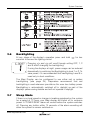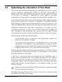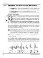
1
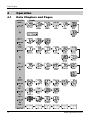
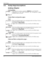
Maxi Display
User Guide
Maxi Display
EMC Conformance
All Raymarine equipment is designed to the best industry standards for
use in the recreational marine environment. The design and
manufacture of Raymarine equipment conforms to the appropriate
Electromagnetic Compatibility (EMC) standards. Correct installation is
required to ensure that performance is not compromised.
Important
Suitability
Due to the wireless communication systems used in Micronet
instruments they are only recommended for use on boats up to 18
metres (60 ft.) Before installing to a boat of aluminium, steel or
Carbon Fibre construction, please consult www.raymarine.com.
Aid to Navigation
Like any other electronic instruments your Micronet system is designed
to serve only as an aid to navigation and it remains the skippers
responsibility to maintain a permanent watch and be aware of
developing situations.
Dismantling the product
Any attempt to take a Micronet product apart will invalidate the warranty.
The battery may only be replaced by a person trained and approved for
this purpose.
Safety and Disposal
Your Maxi Display contains Manganese Lithium Dioxide batteries which
should be disposed of correctly. Do not dispose of any instrument in
domestic waste. Refer to regulations in force in your country.
If in doubt return the instrument to Raymarine for correct disposal.
Contents
1
Key Features
2
2
System Overview
3
2.1
2.2
2.3
2.4
2.5
2.6
2.7
3
3
3
4
4
5
5
3
4
5
Display Features Remote Control Switching the System On and Off Chapter and Page operation Power Management and Battery Life Backlighting Sleep Mode -
Performance Functions
6
3.1
3.2
3.3
3.4
6
7
8
10
Automatic Pages Optimising True Wind Optimising your start with the Maxi Display During the Race -
Operation
14
4.1
4.2
4.3
4.4
14
15
16
17
Data Chapters and Pages Audible Signals and Alarms Page Hiding Operating the Maxi Display using the control button -
Setup and Calibration
18
5.1
5.2
5.3
5.4
18
19
19
20
Setup and Calibration Organisation Setup and calibration Operation Editing Setup Data Setup Page Descriptions -
6
Seatrial and Calibration
26
7
Installation
27
7.1 Bracket mounting 7.2 Bulkhead mounting -
27
27
8
Maintenance and Fault Finding
29
8.1 Care and Maintenance 8.2 Fault Finding -
29
29
Specifications
32
Warranty Information
32
1
Maxi Display
1
Key Features
Simple to Install
Solar Powered: your Maxi Display is powered for life by the Sun. The
innovative technology uses so little current and the power supply is so
efficient, that the Maxi display is independent from your boat's batteries.
Wireless: your Tactick displays communicate by wireless, they can be
sited anywhere on your boat without disruption or cables.
Dedicated to Performance
Optimise your start: the Maxi Display's powerful functions for Distance
and Speed-Trim to the line, Line Bias and Race Timer help you get the
best possible start.
Enhance your performance with the built-in function for Wind Shift and
indicators for Accelerations and Trends.
Simplify your tidal navigation with the Maxi Display's Set, Drift, Turn
and Course to Steer functions.
True Wind correction: the Maxi Display incorporates sophisticated
correction technology to maximise the accuracy of True Wind calculations.
Easy to Manage
Automatic data selection: the innovative Auto Leg function allows the
display to automatically show the information you need for each leg of
the course.
Page Hiding means you can avoid data duplication on different
displays, minimising the time to select the pages you really need.
Wireless Remote control: your Maxi display can be
controlled and configured from anywhere in the boat
using a Raymarine Remote display.
Excellent visibility
The large, high contrast LCD gives the Maxi Display a wide angle of
view and ensures excellent visibility from anywhere on your boat.
The black background minimises disturbance to your night vision, and
the red/amber option allows you to choose the backlight colour of your
display at night.
2
www.raymarine.com
System Overview
2
System Overview
Ensure that the "Auto Network" procedure described on the yellow
instruction sheet and full Setup and Calibration has been performed
correctly before attempting to use your Micronet system.
2.1
Display Features
2.2
Remote Control
Your Maxi Display is designed to be controlled and configured using a
Raymarine Remote Display. See the user guide supplied with the
Remote Display for details of using the Remote Display in remote control
mode. All references in this user guide to the
,
,
or
buttons refer to the appropriate button on the Remote Display.
If a Remote Display is not available, the single control button
provides a limited control capability, see page 17 for details.
For configuration of the Maxi Display a Remote Display is required
See page 18 for details of configuring your Maxi Display.
2.3
Switching the System On and Off
To switch your Micronet system on or off select any display and press
the
button for 2 seconds. (See page 17 for use of the Maxi Display
control button)
Switch on
www.raymarine.com
Switch off
3
Maxi Display
2.4
Chapter and Page operation
Data is shown on the Maxi Display in Chapters, each containing
several pages of related data. The diagram on page 14 shows the
full set of chapters and data pages available.
For a detailed description of individual data items supported on the
Micronet network, see the Micronet Data user guide on your
product CD or on the Raymarine web site.
Selecting Chapters and Pages:
Use
to scroll through the chapters and
between the pages within a chapter.
and
to move
Pressing
at any time will move on to the next Chapter and on
scrolling through the Chapters the page last selected in that
Chapter will be displayed. Both Chapter and Page selection will
scroll back to the first page once a cycle has been completed.
Pages for which no data is available are displayed as dashes (- - -)
2.5
Power Management and Battery Life
What makes your Maxi display possible is Raymarine's
revolutionary approach to power management. By reducing the
amount of power being used by the electronics and maximizing the
potential of the sun to provide power, the Maxi display becomes a
virtually perpetual device.
Power status is indicated by two icons on the display:
Battery Level
and
Charge Rate
Used together these icons will show the condition of the power
supply.
If the internal battery is fully charged then it does not matter how
much the display is subjected to bright sunlight no further
charging is required, the Charge Rate Indicator will remain low.
If the displays are to be stored for a long period of time before next
use (Over Winter) ensure that the batteries are fully charged before
storage.
Artificial light WILL NOT recharge the battery. Placing your Maxi
Display close to an artificial light will seriously damage the
display. Only recharge in natural daylight.
4
www.raymarine.com
System Overview
2.6
Backlighting
At any stage of the display's operation press and hold
seconds to access the lighting control.
for two
Pressing
and
will scroll through setting OFF, 1, 2
and 3 whilst changing the backlighting.
If using the displays at night, power usage can be reduced
dramatically by switching the Backlighting to level 1 or 2. To
save power, it is recommended that backlighting Level 3 is
used only in dusk conditions.
The Maxi Display can be configured to use either red or amber
backlighting (see page 24). Raymarine recommend that red
backlighting is used whenever possible as this uses less battery power.
Backlighting is automatically switched off in daylight as part of the
display's power saving feature and will not operate in daylight.
2.7
Sleep Mode
If there is no boat speed or change in heading registered on the system
for a period of 12 hours your Maxi display will switch off to conserve
power. A "POWER SAVE" alarm will sound before the system switches
off. Pressing any button within 10 seconds of the alarm sounding will
allow the system to remain switched on.
www.raymarine.com
5
Maxi Display
3
Performance Functions of the Maxi Display
3.1
Automatic Pages
You probably want a different page shown on your Maxi Display for each
leg of the course.
The Maxi display makes this easy by providing a special page: the
AUTO LEG page. Using this feature, you can programme your Maxi
Display to show exactly the information you require for each leg of the
course without the need to manually change pages at each mark
rounding.
For example, consider a boat with three Maxi Displays on a mast
bracket. It may be decided that during the start the data required is
Depart, Line Bias and Race Timer; for the windward leg Boat Speed,
VMG to Windward and Wind Shift; and downwind Boat Speed, VMG
to Waypoint and True Wind Direction. Programming these pages into
the Autoleg page prior to the race would automatically show these
pages for the appropriate leg of the course; leaving the tactician free to
concentrate on the race, not on configuring his instruments.
The legs and the pages displayed can be configured in setup to meet
your specific needs, see page 20.
Similarly, using the Page Hiding function to eliminate duplicate pages
across the three displays reduces the time and key presses required if
a manual reconfiguration of the data displayed becomes necessary.
It is a good idea to programme the remote control display list of your
Remote Display to show your Maxi Displays in the same order as their
physical location on the boat. See the Remote Display user guide.
6
www.raymarine.com
Performance Functions
3.2
Optimising the calculation of True Wind
The wind angle and speed measured by a masthead wind unit is subject
to error caused by aerodynamic effects on the sails, and by heel &
leeway which affect the measurement geometry of the system. The size
of the error is variable, it depends on many factors: the boat
characteristics, wind speed, wind angle, air temperature, humidity, etc.
If not corrected, these errors give rise to problems when sailing, typically
you will see a false shift of around 15 degrees in the Wind Direction
when tacking or gybing and a false change of around 15 percent in the
True Wind Speed when changing from an upwind to a downwind course.
Traditionally these errors have been corrected by a complex and time
consuming calibration process, but the Maxi Display has changed all
that. Raymarine have simplified the process and the Maxi Display
incorporates unique technology that makes correction quick and simple.
Raymarine has made two breakthroughs:
-
Sophisticated built in corrections that dramatically reduce the
errors for the majority of boats.
-
An intuitive one step process to immediately enter a fine tuning
adjustment. For example, if the wind direction is seen to be ten
degrees high on the current tack upwind just enter a ten degree
negative adjustment in the upwind angle setup page.
Wind Angle and Speed corrections are generated by the Maxi Display
and transmitted to the Micronet network, so all displays on the network
show accurate wind information.
If the built in corrections are not sufficient for your particular boat, a
single upwind, downwind and wind speed adjustment in low, medium
and strong winds will normally be sufficient to fully calibrate your system.
Adjustment values can be simply identified by monitoring the wind
speed and direction on any display, or by viewing a graph on your
Remote Display.
Displays manufactured before 2010 will require a software upgrade
to show corrected wind data.
See Setup on page 23 and 24 to switch on the built in corrections and
for details of the fine tuning pages.
www.raymarine.com
7
Maxi Display
3.3
Optimising your start with the Maxi Display
The Maxi display provides three functions to help you get a great start:
The Depart page shows your distance from the start line and how
much faster (or slower) you must sail to hit the line at the start signal.
The Race Timer gives you a visual and audible count down.
The Line Bias page helps you choose the best position on the line.
Using the Depart page
Approaching the start, it is vital to know your distance from
the line and whether you will arrive before or after the signal.
The large digits show your distance from the nearest point
on the line in distance units or boat-lengths (see page 23).
A negative distance shows that the boat is to windward of the start line,
not that the boat is on the course side of the line; i.e. for a downwind
start, a negative distance shows you are approaching the line correctly.
The small digits show the change in speed required for you to arrive at
the line at the signal; a negative value means that you must decrease
your speed to avoid arriving early.
These calculations rely on GPS data, so they are subject to error,
particularly as the distance from the line becomes small. Do not rely on
this information to determine if you are over the line at the start. Rather,
you should use the data to help optimise your approach to the line.
Before using the Depart function, you must configure the Boat
Length and GPS Bow parameters in setup; see page 23.
Initialising the Depart page
With the depart page displayed, approach one end of the start line as if
starting; press
when the bow touches the line. A popup page shows
that the first line position has been captured. Repeat at the other end of
the line. The popup shows the second line position has been captured.
8
www.raymarine.com
Performance Functions
The line for Depart calculations is between the positions you set. Set
your points as close to the ends of the actual start line as possible.
Modifying the start line points
If it is necessary to modify one of the points, press
while at the
correct location; the popup will show that position 1 has been captured.
Pressing
or
while the popup is visible will allow you to set the
captured location to position 2. or to discard it (-).
The position is captured at the moment
is pressed.
Starting and Start Line Bias
When the starting line is laid at exactly right
angles to the wind, the distance sailed to
the windward mark is the same wherever
the boat starts on the start line. In real racing
there is often a favoured end to the line.
If you start at the favoured end, you are
upwind and therefore ahead of a boat
starting at the other end of the line. The
larger the Line Bias angle, the more you
gain from starting at the favoured end.
The diagram shows how this works in practice.
Your Maxi Display can calculate and display the Line Bias angle and the
favoured end of the line.
To initialise the line bias display
Go to the Line Bias page, sail directly along the start line,
then press
. The Line Bias angle and the favoured end
of the start line are displayed. The line bias display is
continually updated taking account of wind shifts that may
occur during the pre-start period.
Using the Start Timer
The most convenient way to operate the race timer is to use
the Timer Page of the Remote Display. Once started the
countdown is available on all displays. See the Remote
Display user guide for details of operating the race timer.
www.raymarine.com
9
Maxi Display
3.4
During the Race
While racing, you are continually trimming the sails and making course
adjustments in order to maximise your speed towards the next mark. It
is important to know whether changes are increasing or decreasing your
performance. The Maxi Display provides Trend and Acceleration
functions to help with this:
The Speed, SOG, VMG-WIND and VMG-WPT pages can be configured
to show Trend or Acceleration indicators: arrows to the right indicate
increasing speed, arrows to the left indicate decreasing speed.
In Acceleration mode, the arrows at the bottom of the display indicate
whether the boat is accelerating or decelerating; they are not shown
when the speed is stable
In Trend mode, the arrows show whether the overall speed trend is
upwards or downwards from a reference speed. By default, the reference
speed is calculated as a rolling average of the actual speed.
Pressing
will set the reference speed equal to the current boat speed
(or SOG, VMG as appropriate); the new reference speed will briefly be
shown flashing and may be edited using
and
. Pressing
again will return the reference speed to auto calculate mode.
In both modes, the number of arrows displayed indicates the magnitude
of the change; more arrows means a greater acceleration or a faster trend.
The sensitivity of the trend and acceleration indication can be configured
in setup, see page 22.
Boat Speed Trim
The Speed page can be configured to show your
acceleration or the speed trend. Use this to assess changes
in sail trim.
Sailing upwind.
VMG to Windward
To get to the windward mark as quickly as possible it is
necessary to balance pointing angle against boat speed to
maximise the speed directly towards the wind (this speed is
called the Velocity Made Good to Windward).
10
www.raymarine.com
Performance Functions
The Maxi Display automatically calculates your VMG to windward and
the VMG-Wind page provides acceleration or trend arrows to help you
assess the impact of changes to your course and sail trim.
Wind Shift
Like most things in sailing, the wind does not remain constant in either
strength or direction. Every shift in the wind requires the boat to alter its
heading in order to maintain a close hauled course. A shift that allows
the boat to change its heading closer to the Mean Wind Direction is
called a "lift"; a shift that forces the boat to change course away from the
Mean Wind Direction is known as a "header".
In an oscillating wind, a boat that
regularly tacks when headed will spend
more of its time sailing a lifted course and
will sail a shorter distance to the
windward mark than a boat that regularly
sails a headed course. This gives the
boat sailing in the lifts a considerable
advantage.
In the diagram, the boat on the right sails
a shorter course by tacking when headed
and thereby sailing mostly in lifts.
The system automatically calculates the mean wind direction by
averaging the true wind direction over a period of time
Sail your boat for maximum speed and use the Maxi Display to identify
the headers and lifts to help you decide when to tack or gybe.
Permanent wind shifts can be recognised as a constant header on
one tack, and a constant lift on the other tack. In this situation, you can
reset the mean wind direction as follows:
1. Go to the Wind Shift page
2. Press
, the mean wind direction is reset to the current True Wind
Direction.
3. The new value is displayed; if required, it may be adjusted using
and
.
Resetting the mean wind direction manually disables averaging
until the system is switched off.
www.raymarine.com
11
Maxi Display
Sailing Downwind
Sailing downwind, it is rarely fastest to aim directly for the mark. Usually
it is better to sail at a higher angle to increase boat speed and gybe as
necessary to reach the mark. The increase in speed can more than
compensate for the additional distance sailed. In technical terms, you
aim to maximise your VMG (Velocity Made Good) towards the mark.
Use VMG-WP (VMG to Waypoint) together with the True
Wind Angle to optimise your VMG to the downwind mark
Use the SHIFT page to help you time your gybes. Aim to
gybe on lifts, to keep sailing on the headed tack.
Sailing in Tidal Waters
When you are sailing in tidal conditions, your boat's actual Course Over
the Ground (COG) and Speed Over the Ground (SOG) may differ
considerably from the heading of the boat and the speed through the
water shown by the speed sensor.
The Maxi Display provides the following functions to make your tidal
navigation easier.
Turn
When steering towards a waypoint in tidal conditions, it is
often difficult to assess the course to steer to keep on the
direct track to the mark. Your Maxi Display automatically
indicates when the course you are steering is taking you off
the direct track to your waypoint.
The direction and required angle of turn is displayed.
Course
Used in similar circumstances to the Turn page, the Course
page shows the course to steer to track directly to the
waypoint.
12
www.raymarine.com
Performance Functions
Drift and Set
Because the boat is not always moving directly in the
direction of its compass heading you need to know the
direction (SET) and the speed (DRIFT) by which the boat is
being pushed off course. Tactically this is important when
assessing when to tack or gybe to round a mark or clear an
obstruction or headland.
Your Maxi Display automatically calculates this information using
information from your GPS, boat speed and compass. The calculated
set angle is rounded to the nearest ten degrees.
Set and Drift as calculated includes the effect of both tide and
leeway. Therefore the value will be different on opposite tacks,
depending on whether the boat is sailing into or against the tide.
This will be especially noticeable when the tidal effect is small.
In conditions of little tide, this calculation is very sensitive to
inaccuracies in the calibration of your speed and compass
transducers. It is not recommended that you rely on the accuracy
of this calculation when the tide speed is less than one Knot.
A flashing indicator will alert you if the calculated values are
uncertain.
See the Calibration Guide for information on how to maximise the
accuracy of the calibration of your speed and heading transducers.
www.raymarine.com
13
Maxi Display
4
Operation
4.1
Data Chapters and Pages
14
www.raymarine.com
Operation
4.2
Audible Signals and Alarms
At stages during its operation your Maxi Display will beep to indicate
alarms or moments of importance.
Power-up
The display will beep once as it switches on.
Button Press The display will beep once each time a button is
pressed. A second beep is issued after a 2 second hold
down of the
button.
Timer
The display will beep once at each minute of the
countdown.
With 1 minute left to go a beep will sound every 10
seconds.
With 10 seconds to go a beep will sound every second.
Countdown complete will be indicated by a single burst
of three beeps.
Alarm
Continuous bursts of three beeps will indicate an alarm.
The alarm activated will be indicated on the display,
accompanied by the flashing (BELL) symbol.
Pressing any button will silence the alarm. See fault finding section,
page 29.
The Alarms below will be indicated on the Maxi Display, however they
must be configured using another Raymarine Micronet display
connected to the network. See the appropriate display user guide for
details of configuring alarms.
Depth Shallow Alarm
The water depth has fallen below the preset alarm level.
This alarm does not sound as the depth increases above
the preset alarm level.
Depth Deep Alarm
The water depth has increased above or fallen below the
preset alarm level.
www.raymarine.com
15
Maxi Display
Wind High Alarm
The wind speed has increased beyond the preset alarm
level.
Cross Track Error Large Alarm
A large cross track error has been alerted by the GPS.
Waypoint Arrival Alarm
A waypoint arrival signal has been received from the GPS.
The waypoint name is shown on the top line of the display.
4.3
Page Hiding
When shipped from the factory a number of the less commonly used
pages are hidden by default; they do not appear when you scroll
through the chapters and pages. You may hide additional pages, or
unhide those already hidden to set up your Maxi Display for your
individual requirements. The diagram on page 14 shows the pages that
are hidden by default.
To hide unwanted pages:
Press and hold
to enter set up
Press
to reach the OPTIONS chapter
Press
to reach the Page Hiding page
Press
to activate page hiding for 5 minutes
Press and hold
to exit setup.
Once page hiding is activated:
Use
,
and
to navigate to the page to be hidden
Press
for 2 seconds to hide the page.
A period of 5 minutes is allowed to select pages to hide.
16
www.raymarine.com
Operation
To clear Page Hiding and return to all pages visible:
Press and hold
to enter set up
Press
to reach the OPTIONS chapter
Press
to reach the Pages Hidden page; the display shows the total
number of pages hidden
Press
to return to all pages visible
Press and hold
to exit setup.
The factory reset function in setup will return page
hiding to the default setting.
4.4
Operating the Maxi Display using the control
button
The Maxi Display is designed to be operated and configured using a
Raymarine Remote Display; however for emergency use, there is a
limited control function available via the single control button.
To switch on the system press the button for two seconds.
The display starts up in Chapter mode; quick presses of the button scroll
through the available chapters, the data page most recently accessed in
each chapter is shown.
To change the page, press the button for two seconds; the display
changes to Page mode (the legend PAGE MODE is shown briefly).
Quick presses of the button scroll through the available pages in the
chapter.
To return to Chapter mode press the button for two seconds again
(the legend CHAPTR MODE is briefly displayed).
To switch off the system press the button for four seconds
Lighting any press of the button will switch on backlighting for the
display (this will be auto dimmed in daylight).
It is not possible to configure the Maxi Display using its control
button. This must be carried out using a Raymarine Remote
Display.
www.raymarine.com
17
Maxi Display
5
Setup and Calibration
5.1
Setup and Calibration Organisation
Setup is organised into Chapters, each comprising a number of Pages.
The Maxi Display is designed for remote control; the built in setup mode
only provides settings for functions that are local to the Maxi Display.
These settings are configured by operating the Maxi Display setup
function in remote contol mode using a Raymarine Remote Display. See
the Remote Display user guide for details of remote control mode.
The diagram below shows the layout of the available setup chapters and
pages on the Maxi Display. For a full description of each setup page
refer to section 5.4.
Generic system setup and configuration is carried out directly from the
Remote Display. See the Remote Display user guide for details.
CHAPTER
RC
PAGES
RC
RC
Autoleg
Mode
RC
Upwind
Page
Start
Page
RC
RC
Start
Page
RC
RC
RC
RC
RC
Trends &
Acceleration
Tack to Tack
Correction
RC
RC
Airflow
Mode
RC
RC
Leg 2-3
Angle
Leg 3
Page
RC
Average
Speed
Maximum
True Wind
RC
GPS
Bow
Line Distance
Units
RC
RC
Downwind Angle
Correction
RC
Backlight
Control
Wind Rod
Selection
RC
RC
Demo
Mode
Factory
Reset
RC
RC
Pages
Hidden
Backlight
Colour
Backlight
Control
Master
Demo
Mode
Factory
Reset
Hull
Transmitter
Wind
Transmitter
Wireless
Interface
Mast
Rotation
Man
Overboard
Type 6 to
Type 9
RC
RC
This
Display
18
Maximum
Speed
Boat
Length
RC
Leg 2
Page
RC
RC
RC
RC
Leg 1-2
Angle
Minimum
Depth
RC
RC
RC
RC
Upwind Angle
Correction
Page
Hiding
RC
Leg 1
Page
Maximum
Depth
RC
Downwind
Page
RC
RC
RC
Trip
RC
www.raymarine.com
Setup and Calibration
5.2
Setup and Calibration Operation
To enter Setup
It is not possible to enter setup mode while the Race Timer page
is currently visible. Scroll to a different page in order to enter setup
Press and hold
, the first chapter title page is displayed.
To change the active chapter
Press
repeatedly until the desired chapter title page is displayed.
At the end of the chapter cycle, the display returns to the first chapter
title page.
If you are currently on a chapter parameter page, you must return to the
chapter title page before you can move to a new chapter.
To access the setup pages
Use
to scroll through the pages,
5.3
returns to the previous page.
Editing Setup Data
Parameter values may be one of three types:
A user editable numeric value (for example, the Autoleg 1-2 parameter).
To edit a numeric parameter value:
Press
Use
. The value data will begin to flash.
and
Press
to adjust the value.
again to set the new value.
A list of options (for example, the Autoleg Start parameter).
To select a parameter option from a list:
Press
Use
.The parameter option will begin to flash.
and
Press
to select the option required.
again to set the new option.
A toggle between two alternative options (for example the Auto Leg
Mode parameter).
To toggle between alternate parameter settings:
Press
. The setting will toggle between the options.
www.raymarine.com
19
Maxi Display
5.4
Setup Page Descriptions
Autoleg Chapter
Autoleg Mode
There are two modes available, SIMPLE and ADVANCD.
Depending on the mode selected, the configuration pages
available are as follows:
Simple Mode configuration pages
Start
Sets the Autoleg page to be displayed while the Race Timer is
counting down to the start.
The default is Race Timer.
Pages can be selected from any currently unhidden page.
Upwind
Sets the autoleg page to be displayed while the apparent wind
angle is between head to wind and 90 degrees.
The default is Wind Shift.
Pages can be selected from any currently unhidden page.
Downwind
Sets the autoleg page to be displayed while the apparent wind
angle is between 90 and 180 degrees.
The default is True Wind Direction.
Pages can be selected from any currently unhidden page.
Advanced Mode configuration pages
Start
Sets the Autoleg page to be displayed while the Race Timer is
counting down to the start.
The default is Race Timer.
Pages can be selected from any currently unhidden page.
Leg 1
Sets the autoleg page to be displayed while the apparent wind
angle is between head to wind and the leg1-2 changeover
angle.
The default is Wind Shift.
Pages can be selected from any currently unhidden page.
20
www.raymarine.com
Setup and Calibration
Leg 1-2 Angle
The angle at which the auto leg page switches from the Leg1
page to the Leg 2 page.
The default is 60 degrees.
Leg 2
Sets the autoleg page to be displayed while the apparent wind
angle is between the leg 1-2 changeover angle and the leg 2-3
changeover angle. The default is True Wind Direction.
Pages can be selected from any currently unhidden page.
Leg 2-3 Angle
The angle at which the auto leg page switches from the Leg2
page to the Leg 3 page.
The default is 120 degrees
Leg 3
Sets the autoleg page to be displayed while the apparent wind
angle is between the leg 2-3 changeover angle and 180
degrees. The default is VMG to Windward.
Pages can be selected from any currently unhidden page.
Memories Chapter
All memories are cleared when the system is powered on.
Trip
Clears the trip memory, resets to 0.0.
Minimum Depth
Resets the Minimum Depth memory; resets to the current
depth.
Maximum Depth
Resets the Maximum Depth memory; resets to the current
depth.
www.raymarine.com
21
Maxi Display
Maximum Speed
Clears the Maximum Speed memory; resets to the current
speed.
Average Speed
Clears the Average Speed memory; resets to the current
speed.
Maximum True Wind Speed
Resets the Maximum True Wind Speed memory; resets to the
current true wind speed.
Race Chapter
Trends
Sets the functionality of Trend or Acceleration arrows for the
Speed, SOG, VMG-WIND and VMG-WP pages.
The options are: OFF, ACCEL-L, ACCEL-M, ACCEL-H,
TREND-L, TREND-M and TREND-H.
When set to OFF, trend/acceleration arrows are not shown.
When set to ACCEL, acceleration arrows are shown.
The three values ACCEL L, ACCEL M & ACCEL H indicate LOW,
MEDIUM and HIGH sensitivity.
When set to TREND, trend arrows are shown.
The three values TREND-L, ACCEL M & ACCEL H indicate LOW,
MEDIUM and HIGH sensitivity.
See page 10 for details of trend/acceleration functions.
Tack to Tack Correction
A value that corrects the speed displayed when the boat is on
starboard tack, to take account of inherent differences of the
measured speed on opposite tacks, e.g caused by off-centre
installation of the transducer.
By default the correction is zero,
See the Calibration Guide for details on setting a Tack to Tack correction.
22
www.raymarine.com
Setup and Calibration
Boat Length
Sets the length of the boat in feet.
The default is 30 Feet.
GPS Bow
Sets the distance in feet of the GPS antenna from the bow of
the boat. The default is 30 Feet.
(Depart) Line Distance Units
Sets the units to be used for showing the distance to the start
line, the options are Feet, Metres, Yards or Boat Lengths (see
Boat Length parameter above)
Airflow Chapter
RC
Airflow Corrections Mode
Switches the built in default corrections ON or OFF
The following airflow correction pages are only visible if Airflow
Corrections mode is set to ON.
Adjustments are applied to the correction curve in the current wind
speed band. For optimum accuracy, adjustments should be applied
in light, medium and strong winds ( 5-10, 15-20, 20-25 knots).
See the Calibration Guide for details of Airflow correction
RC
RC
Upwind Angle adjustment
Modifies the upwind angle correction.
Whilst tacking upwind, if the Wind Direction on the current tack
is seen to be ten degrees high, apply an adjustment value of 10. If low, apply a + adjustment.
Downwind Angle adjustment
Modifies the downwind angle correction.
Whilst gybing downwind, if the Wind Direction on the current
gybe is seen to be ten degrees high, apply an adjustment value
of -10. If low, apply a + adjustment.
www.raymarine.com
23
Maxi Display
RC
RC
Wind Speed adjustment
Modifies the wind speed correction to balance readings upwind
and downwind. After turning from upwind to downwind, or
downwind to upwind, if the Wind Speed is now seen to be
reading 1.5 knots high, apply an adjustment value of -1.5. If low,
apply a + adjustment.
Wind Transmitter selection
Selects the type of wind transmitter installed. The options are:
STANDRD and VERTICL.
Do not change this setting unless you have installed a
new type of Wind Transmitter. Changing this selection
clears all Airflow adjustments previously entered and
reverts to the default corrections for the type of transmitter
now selected. In this case, you will need to repeat the
adjustment process.
Options Chapter
Page Hiding
Enables the user to hide pages.
See page 16 for the page hiding process.
Less commonly used pages are hidden by default; see
page 14 for details of these pre-hidden pages.
Pages Hidden
Displays the number of hidden pages and permits Page Hiding
to be cleared, returning to all pages visible.
See page 17 for the page unhiding process.
Backlight Colour
Selects the backlight colour for the display.
The options are RED or AMBER.
Raymarine recommend that, to save power, RED
backlighting is used whenever possible.
Backlight Control
Configures the display to control the system backlighting or just
its own backlighting.
The options are: Network (NETWK)/Local.
24
www.raymarine.com
Setup and Calibration
Master
Sets the capability for the Display to aquire network mastership.
When set to ON the current display will seize network
mastership if mastership is available.
When OFF, the current display may be assigned mastership by
the unit that is giving up mastership. The default is OFF.
Raymarine recommend you leave this setting at OFF
unless advised by www.raymarine.com.
Demonstration Mode
Allows the display to show information when NOT installed as
part of a Micronet system for demonstration purposes only.
Displays will return to default OFF on power down.
Factory Reset
Returns all the calibration setting to the factory default values.
Health Chapter
Software Version/Network Nodes
Displays the software version, battery level and charge rate to
assist in troubleshooting and fault finding.
If the display is the "Master" (the one used to switch on the
system) then the number of items (nodes) in the system will be
shown. If the display is a "Slave" (was switched on by the system)
then the signal strength to the "Master" will be shown in place of
the number of nodes.
Hull Transmitter Signal Strength
Shows the software version (large digits), signal strength and
battery condition (level and charge rate) of the Hull Transmitter
to assist in trouble shooting and fault finding
Similar information pages are available for other transmitters if they
areconnected to the micronet network, for example:
Wind Transmitter (identified as WIND)
Wireless (NMEA) Interface (NMEA)
Mast Rotation Transmitter (MASTo)
Man Overboard Transmitter (MOB)
www.raymarine.com
25
Maxi Display
6
Seatrial and Calibration
Once a Raymarine Micronet system has been installed on the vessel and
Auto Networking has been completed it is necessary to carry out
Calibration.
It is not safe to use the displays for navigational purposes until
Calibration has been carried out correctly.
Accurate calibration is essential for successful use of the Maxi
Display’s advanced functions. In particular, the calculation of Set
and Drift is sensitive to errors in the measured boat speed and the
compass heading and deviation. To ensure the maximum
accuracy, calibration must be carried out with great care.
System calibration cannot be carried out using the Maxi Display, use
a Remote Display for this purpose. Refer to the Remote Display guide
and the Calibration Guide for the system calibration procedure.
Airflow calibration is carried out on the Maxi Display, using a
Remote Display in remote control mode; see the Remote Display
guide for details of remote control mode.
For details of Airflow calibration, see Optimising the Calculation of
True Wind (page 7) and the Airflow chapter in Setup (page 23).
For full calibration information, including airflow correction, see the
Calibration Guide.
26
www.raymarine.com
Installation
7
Installation
Your Maxi Display may be mounted on a Raymarine Mast Bracket or
directly onto a bulkhead.
7.1
Bracket mounting
Raymarine recommend the use of a Raymarine supplied bracket,
which is designed to optimise the radio reception of the Maxi Display.
Please refer to the installation instructions provided with the bracket.
If using a customised bracket, you should avoid the use of conducting
material (e.g Aluminium, Carbon Fibre, etc). If this is not possible, you
must provide the maximum cut-out area behind each Maxi Display to
allow free circulation around the antenna. See the mounting template for
details of the cutout required. If in doubt, refer to www.raymarine.com.
7.2
Bulkhead mounting
If installing your Maxi Display on a carbon fibre or metal bulkhead, it
may be necessary to make a cutout to ensure adequate radio
circulation around the antenna. Refer to the Mounting Template for
details of the cutout required. If in doubt, refer to www.raymarine.com.
Use the template provided to select a suitable position for mounting.
Ensure the mounting surface is flat.
Leave space between displays for sun covers.
Avoid areas where damage may occur (winch handles, feet, warps etc.)
Check for clarity of vision and ease of access to the control button.
Where there is no access to the rear of the mounting surface
Only use the screws provided with the display and take care not to
over tighten the screws. Incorrect or overtightened screws may
cause the moulding to crack; this will invalidate your warranty.
Position the supplied Template carefully before starting.
1. Drill four 2.5mm holes as marked on the template.
2. Refer to the diagram below. Using your fingers, carefully snap the
facia of the display off the main body by pulling in the direction of the
arrows.
Take care not to drop the button pad.
www.raymarine.com
27
Maxi Display
3. Remove the four captive M4 nuts from the plastic moulding and
attach the display to the mounting surface using the four self tapping
screws provided.
4. Check the display is perfectly level; carefully position the button
insert into the slot and snap the facia back into position.
Where access is available to the rear of the mounting surface
Do not bolt through from the front or replace the plastic nuts with
metal nuts. This may cause the moulding to crack and will
invalidate your warranty.
This method allows for maximum security of a permanently mounted
display. Position the supplied template carefully before starting. Use
bolts of a suitable length inserted from the rear. The internally fitted
plastic nuts will prevent overtightening.
If the internal plastic nuts are displaced or become damaged,
remove the bezel as described above and replace with the spare
nuts provided.
Take care not to drop the button pad.
28
www.raymarine.com
Maintenance and Fault Finding
8
Maintenance and Fault Finding
8.1
Care and Maintenance
All Micronet products are totally sealed against water and are not
serviceable. Any attempt to take a Micronet product apart will invalidate
the warranty.
To clean, use only a damp, soft cloth. No detergents, solvents or
abrasives should be used. To avoid damaging a Micronet display unit
we recommend storing in the supplied soft pack when not in use.
If the displays are to be stored for a long period (e.g. over winter) ensure
that the batteries are fully charged before storage.
8.2
Fault Finding and Solution
My Maxi Display does not start when I switch on the system
Check that you have correctly carried out auto-networking to connect
your Maxi Display to the network. See the yellow Auto Networking sheet.
My Remote Display does not go into Remote Control mode
a) Remote control mode is not available for 30 seconds after the system
is switched on. Wait 30 seconds and try again.
b) Remote control was not supported on displays manufactured before
2006. Ensure that you switch on the system using a display
manufactured after 2006, the Remote Display or a Maxi Display.
My Remote display does not find my Maxi Display
Use the Remote Display setup function to reset the remote control list,
see the Remote Display user guide for details. Wait 30 seconds and try
remote control mode again.
The DRIFT display is showing erratic errors
Your Compass and Speed transducers require calibration. See the
Calibration Guide for details.
Power No Volts alarm sounds
The Hull Transmitter and Wireless (NMEA) Interface must be connected
to external power supplies. If this connection is not made, then you will
see this alarm 10 seconds after powering up your system. Any DC
voltage between 9 and 30V is sufficient to power the Hull Transmitter and
Wireless (NMEA) Interface.
www.raymarine.com
29
Maxi Display
Power Save Alarm sounds
There has been no significant data activity on the network. The alarm
sounds to indicate that the display system will turn itself off. To continue
using the system press any button to cancel the alarm.
Lost Network Alarm sounds
This indicates that one or more displays have lost communication with
the Master. Either there is a problem with the Master display or the
displays in question have been moved out of effective range. The
displays will switch off after sounding the alarm to save power.
The “Master” display is the display used to power up the entire system.
This may be different each time the system is used. If you are uncertain
which display is the master, switch off the system and switch on again.
The display which you switched on is now the Master.
A single display flashes the battery symbol and then switches off
The battery level is low on the particular display affected. Connect to a 9
to 30V DC power source or leave in bright sunlight for 12 hours minimum
to recharge the display's internal battery. If the particular display is the
system Master then the other displays will sound the "Lost Network"
alarm. To continue using the rest of the system power down and restart
the system from another display.
Low Battery Alarm sounds
The power level is low in the Hull Transmitter, Wireless (NMEA) Interface
or Wind Transmitter. Enter Setup mode on the Remote Display and scroll
to the Health Chapter. Check the battery levels of the Transmitters and
Interface Box. The battery level icon should show 1, 2 or 3 bars to ensure
correct operation. Connect the Hull Transmitter or Wireless (NMEA)
Interface to a 9 to 30V DC power source for 12 hours minimum to
recharge the internal battery. Leave the Wind Transmitter in bright
sunlight for 12 hours minimum to recharge its internal battery.
Data is shown as dashes
The information is not being transmitted to the displays. There may be
lost communication between the Wind Transmitter or Hull Transmitter
and the displays. Enter Setup mode on the Remote Display and scroll to
the Health Chapter. Check the signal levels of the Hull and Wind
Transmitters. The signal level should show a value greater than 3 to
ensure correct operation.
30
www.raymarine.com
Maintenance and Fault Finding
Boat Speed reads 0
Information being transmitted from the Hull Transmitter is being received
with a zero value. Check the paddle wheel for fouling, clean it and make
sure it turns easily.
Wind Speed reads 0
Information being transmitted from the Wind Transmitter is being
received with a zero value. If the anemometer cups at the top of the mast
are turning and the wind speed reads zero then there is a problem with
your Wind Transmitter.
No NMEA data showing on external displays
Enter Setup mode on the remote display and scroll to the Health
Chapter. Check the signal level and battery status of the Wireless
(NMEA) Interface. If the signal level shows a value greater than 3 then
check the data connections and the settings of the NMEA equipment to
ensure that NMEA 0183 is being transmitted correctly.
The Depth Alarm does not sound
If the actual water depth is shallow and the alarm has not sounded it is
most likely that the alarm is switched off. Enter Setup mode on the
Remote Display and scroll to the Depth Chapter. Ensure the Depth
Alarm settings are correct.
Compass information displayed on the system does not agree
with the main steering compass.
Ensure that the main steering compass has been swung correctly and
is showing correct information. Ensure that the Compass Calibration
procedure has been correctly completed (see the Remote Display user
guide). If there are still differences, look for magnetic objects (loud
speakers, pumps and motors, etc.) close to the Compass Transducer
and try mounting the transducer in an alternative location. After
changing position of nearby equipment or the Compass Transducer it
will be necessary to re-calibrate the compass.
www.raymarine.com
31
Maxi Display
Specifications
Height of digits: 50mm (2")
Backlighting:
3 levels (optional red or amber) with daylight shutoff
System-wide or local control
Power:
Solar Powered
300 hrs autonomy by day, 7 nights at brightest
backlighting,
20 nights at economy backlighting without charge
Units of display: Boat Speed (knots, km/hour, statute miles/hour)
Distance (nautical miles, statute miles, kilometres)
Depth (metres, feet, fathoms)
Wind Speed (knots, metres per second, Beaufort)
Alarm:
Audible Alarms for Depth, Wind, Cross Track Error,
Waypoint Arrival
Weight:
365g (0.8lbs)
Operating Temp: -10° to +60°C (14° to 140°F)
Frequency:
868 MHz or 916 MHz
Warranty
For warranty details for this product see the Raymarine website at
www.raymarine.com/warranty.
32
www.raymarine.com
www.raymarine.com
Maxi Display
www.raymarine.com
www.raymarine.com
Maxi Display
This device complies with Part 15 of the FCC rules. Operation is subject to
the following two conditions. (1) This device may not cause harmful
interference, and (2) this device must accept any interference received,
including interference’s that may cause undesirable operation.
Note: the manufacturer is not responsible for any radio or TV interference
caused by unauthorized modifications to this equipment. Such modifications
could void the user’s authority to operate the equipment.
Raymarine Ltd hereby declare that the Micronet Maxi Display is in
compliance with the essential requirements and other relevant provisions of
Directive 1999/5/EC.
www.raymarine.com