1
MANUAL
12 2 3 / 3 3
12 2 5 / 3 5
12 2 7 / 3 7
MultiMode™
MOTOR CONTROLLERS
© 2000 CURTIS INSTRUMENTS, INC.
DESIGN OF CURTIS PMC 1200 SERIES
CONTROLLERS PROTECTED BY U.S.
PATENT NO. 4626750.
CURTIS PMC
235 East Airway Boulevard
Livermore, California 94568 USA
Tel: 925-961-1088
Fax: 925-961-1099
www.curtisinst.com
1223/33, 1225/35, 1227/37 Manual
p/n 16879, Rev. B: September 2000
1223/33, 1225/35, 1227/37 Manual
p/n 16879, Rev. B: September 2000
© 2000 CURTIS INSTRUMENTS, INC.
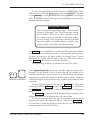
This electronic version of the 1223/33, 1225/35, 1227/37 manual is offered as a
convenience to our customers. You may download any or all of it.
If you would like a hard copy of the published manual, please order it by part number from
the Curtis office nearest you.
The electronic version of the manual is identical to the printed version published in May
1996 (Rev. A) with the following exceptions:
The corrections provided in the Update Sheet published February 1997
have been incorporated into the Rev. B manual. These are:
Tables 8 and 9: Status LED codes updated
Fig. 2: minor corrections to several mounting dimensions
Fig. 12: ET wiring corrected
Fig. B-3: footpedal wiring corrected
Several other minor corrections have also been made, including:
p. 57:
“Revert to Previous Settings” changed to “Reset All Settings”
p. 61:
minor changes in the Diagnostics Menu to make it consistent with
the revised Tables 8 and 9
p. 62:
“No Faults Present” changed to “No Known Faults”
Bookmarks have been added to the electronic version to speed the process of going directly
to a particular part of the document.
CURTIS INSTRUMENTS, INC.
200 KISCO AVENUE
MOUNT KISCO, NEW YORK 10549 USA
☎ 914-666-2971 FAX 914-666-2188
■ CURTIS PMC
235 EAST AIRWAY BOULEVARD
LIVERMORE, CALIFORNIA 94550 USA
☎ 925-961-1088 FAX 925-961-1099
■ ADDITIONAL OFFICES located in
Bulgaria, China, England, France, Germany,
India, Italy, Japan, Netherlands, Puerto Rico,
Russia, Sweden, and Switzerland
CONTENTS
CONTENTS
1.
OVERVIEW ....................................................................... 1
2.
INSTALLATION AND WIRING ..................................... 5
1223/33 Controllers ..................................................... 6
1225/35 Controllers ................................................... 10
1227/37 Controllers ................................................... 14
Throttle Wiring ......................................................... 18
5kΩ, 3-wire potentiometer throttle ..................... 18
0–5V throttle ...................................................... 19
Curtis ET-1XX electronic throttle ....................... 20
Speed limit pot ................................................... 21
Auxiliary Driver Output Options ............................... 23
Program 1 ........................................................... 23
Program 2 ........................................................... 23
Emergency reverse (belly button) wiring check ... 23
Switches and Other Hardware.................................... 24
Control switches ................................................. 24
Keyswitch and power enable switch .................... 24
Push switch ......................................................... 24
Brake release switch ............................................. 25
Inhibit ................................................................. 25
Panel indicator LEDs .......................................... 25
Horn ................................................................... 26
Main contactor ................................................... 26
Circuitry protection devices ................................ 26
3.
PROGRAMMABLE PARAMETERS ............................... 27
Acceleration Rate, M1/M2 ......................................... 29
Deceleration Rate, M1/M2 ........................................ 29
Reverse Deceleration Rate, M1/M2 ........................... 29
Maximum Speed, M1/M2 ......................................... 30
Minimum Speed, M1/M2 .......................................... 30
Reverse Speed ............................................................. 31
Creep Speed ............................................................... 32
Emergency Reverse Speed .......................................... 32
Throttle Input Type ................................................... 33
Curtis PMC 1223/33, 1225/35, 1227/37 Manual
12345678901
12345678901
12345678901
12345678901
12345678901
12345678901
12345678901
12345678901
12345678901
12345678901
12345678901
12345678901
12345678901
12345678901
12345678901
12345678901
12345678901
12345678901
12345678901
12345678901
12345678901
12345678901
12345678901
12345678901
12345678901
12345678901
12345678901
12345678901
12345678901
12345678901
12345678901
12345678901
12345678901
12345678901
12345678901
12345678901
12345678901
12345678901
12345678901
12345678901
12345678901
12345678901
12345678901
12345678901
12345678901
12345678901
12345678901
12345678901
12345678901
12345678901
12345678901
12345678901
12345678901
12345678901
12345678901
12345678901
12345678901
12345678901
12345678901
12345678901
12345678901
12345678901
12345678901
12345678901
12345678901
12345678901
12345678901
12345678901
12345678901
12345678901
12345678901
12345678901
12345678901
12345678901
12345678901
12345678901
12345678901
12345678901
12345678901
12345678901
12345678901
12345678901
12345678901
12345678901
12345678901
12345678901
12345678901
12345678901
12345678901
12345678901
12345678901
12345678901
12345678901
12345678901
12345678901
12345678901
12345678901
12345678901
12345678901
12345678901
12345678901
12345678901
12345678901
12345678901
12345678901
12345678901
12345678901
12345678901
12345678901
12345678901
12345678901
12345678901
12345678901
12345678901
12345678901
12345678901
12345678901
12345678901
12345678901
12345678901
12345678901
12345678901
12345678901
12345678901
12345678901
12345678901
12345678901
12345678901
iii
CONTENTS
Direction Input Type ................................................. 34
Throttle Autocalibration ............................................ 35
Throttle Deadband .................................................... 36
Throttle Gain ............................................................. 37
Ramp Shape (Static Throttle Map) ............................ 38
Main Current Limit, M1/M2 .................................... 40
Emergency Reverse Current Limit ............................. 40
Calibration 5: Regen Current Boost ........................... 40
Program 1 Auxiliary Driver ........................................ 41
Program 2 Auxiliary Driver ........................................ 42
Program 4: Brake Holding Voltage ............................ 43
High Pedal Disable (HPD) ........................................ 43
Static Return to Off (SRO) ........................................ 43
IR Speed Coefficient, M1/M2 .................................... 44
Calibration 4: IR Stiffness .......................................... 44
4.
OEM-SPECIFIED, FACTORY-SET PARAMETERS ..... 45
Speed Interlocks ......................................................... 45
Speed Limit Pot Fault ................................................ 45
Main Contactor Fault Check ..................................... 46
Overvoltage ................................................................ 46
Emergency Reverse Check .......................................... 46
Switch Type ............................................................... 47
Input Polarities ........................................................... 47
Emergency Reverse ..................................................... 47
Key Off Deceleration ................................................. 48
Power Saver ................................................................ 48
MultiMode™ ............................................................ 48
5.
INSTALLATION CHECKOUT ..................................... 49
6.
PROGRAMMER OPERATION ..................................... 52
7.
DIAGNOSTICS AND TROUBLESHOOTING ............ 62
8.
MAINTENANCE ............................................................ 66
APPENDIX A
APPENDIX B
APPENDIX C
Glossary of Features and Functions ............. A-1
Throttle Mounting Dimensions .................. B-1
Specifications ............................................... C-1
Curtis PMC 1223/33, 1225/35, 1227/37 Manual
1234567890
1234567890
1234567890
1234567890
1234567890
1234567890
1234567890
1234567890
1234567890
1234567890
1234567890
1234567890
1234567890
1234567890
1234567890
1234567890
1234567890
1234567890
1234567890
1234567890
1234567890
1234567890
1234567890
1234567890
1234567890
1234567890
1234567890
1234567890
1234567890
1234567890
1234567890
1234567890
1234567890
1234567890
1234567890
1234567890
1234567890
1234567890
1234567890
1234567890
1234567890
1234567890
1234567890
1234567890
1234567890
1234567890
1234567890
1234567890
1234567890
1234567890
1234567890
1234567890
1234567890
1234567890
1234567890
1234567890
1234567890
1234567890
1234567890
1234567890
1234567890
1234567890
1234567890
1234567890
1234567890
1234567890
1234567890
1234567890
1234567890
1234567890
1234567890
1234567890
1234567890
1234567890
1234567890
1234567890
1234567890
1234567890
1234567890
1234567890
1234567890
1234567890
1234567890
1234567890
1234567890
1234567890
1234567890
1234567890
1234567890
1234567890
1234567890
1234567890
1234567890
1234567890
1234567890
1234567890
1234567890
1234567890
1234567890
1234567890
1234567890
1234567890
1234567890
1234567890
1234567890
1234567890
1234567890
1234567890
1234567890
1234567890
1234567890
1234567890
1234567890
1234567890
1234567890
1234567890
1234567890
1234567890
1234567890
1234567890
1234567890
1234567890
1234567890
1234567890
1234567890
1234567890
1234567890
1234567890
1234567890
iv
FIGURES
FIGURES
FIG.
1:
Curtis PMC 1221, 1225, and 1227
electronic motor controllers, with
handheld 1307 programmer ................................................ 1
FIG.
2:
Mounting dimensions,
Curtis PMC 1223/33 controllers ......................................... 6
FIG.
3:
Basic wiring configuration with on/off switches,
1223/33 controllers ............................................................. 8
FIG.
4:
Basic wiring configuration with momentary switches,
1223/33 controllers ............................................................. 9
FIG.
5:
Mounting dimensions,
Curtis PMC 1225/35 controllers ....................................... 10
FIG.
6:
Basic wiring configuration with on/off switches,
1225/35 controllers ........................................................... 12
FIG.
7:
Basic wiring configuration with momentary switches,
1225/35 controllers ........................................................... 13
FIG.
8:
Mounting dimensions,
Curtis PMC 1227/37 controllers ....................................... 14
FIG.
9:
Basic wiring configuration with on/off switches,
1227/37 controllers ........................................................... 16
FIG.
10:
Basic wiring configuration with momentary switches,
1227/37 controllers ........................................................... 17
FIG.
11:
Wiring for 0–5V throttle ................................................... 19
FIG.
12:
Wiring for Curtis ET-XXX electronic throttle ................... 20
FIG.
13:
Effect of speed limit pot position on speed curves ............. 21
FIG.
14:
Wiring of speed limit input to enable maximum speed
when no speed limit pot is used ........................................ 22
FIG.
15:
Wiring to check the emergency reverse input wiring
(belly button check) ........................................................... 23
FIG.
16:
Wiring to inhibit operation during battery charging ......... 25
Curtis PMC 1223/33, 1225/35, 1227/37 Manual
v
FIGURES
FIG.
17: Examples of speed curves with the speed limit pot
in its maximum speed position ........................................ 30
FIG.
18: Examples of speed curves with the speed limit pot
in its minimum speed position ........................................ 31
FIG.
19: Example of reverse speed curve ........................................ 32
FIG.
20: Effect of adjusting the neutral deadband parameter ......... 36
FIG.
21: Effect of adjusting the throttle gain parameter ................. 37
FIG.
22: Ramp shape (throttle map) for controller
with maximum speed set at 100%
and creep speed set at 0 ................................................... 38
FIG.
23: Ramp shape (throttle map) for controller
with maximum speed set at 100%
and creep speed set at 10% .............................................. 39
FIG.
24: Ramp shape (throttle map) for controller
with maximum speed set at 60%
and creep speed set at 10% .............................................. 39
FIG.
25: Bench test setup for verifying and adjusting
the controller’s parameters ............................................... 51
FIG.
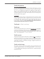
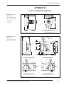
B-1: Mounting dimensions, Curtis PMC standard
5kΩ, 3-wire throttle pot ................................................ B-1
FIG.
B-2: Mounting dimensions, Curtis PMC potboxes ............... B-1
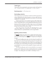
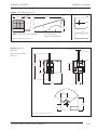
FIG.
B-3: Mounting dimensions, Curtis PMC footpedal .............. B-2
FIG.
B-4: Mounting dimensions, Curtis electronic throttle ........... B-2
Curtis PMC 1223/33, 1225/35, 1227/37 Manual
vi
TABLES
TABLES
TABLE
1: Model comparison chart .................................................... 4
TABLE
2: Throttle styles .................................................................. 19
TABLE
3: Resistors for indicator LEDs ............................................ 26
TABLE
4: Programmable throttle input signal types ........................ 33
TABLE
5: Programmable direction input types ................................ 34
TABLE
6: Configuration options: Program 1 Driver ........................ 41
TABLE
7: Configuration options: Program 2 Driver ........................ 42
TABLE
8: Troubleshooting chart ..................................................... 63
TABLE
9: Status LED fault codes .................................................... 64
TABLE
C-1: Specifications, 1223/33 controllers ............................. C-1
TABLE
C-2: Specifications, 1225/35 controllers ............................. C-2
TABLE
C-3: Specifications, 1227/37 controllers ............................. C-3
Curtis PMC 1223/33, 1225/35, 1227/37 Manual
vii
1 — OVERVIEW
1
OVERVIEW
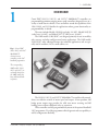
Curtis PMC 1223/33, 1225/35, and 1227/37 MultiMode™ controllers are
programmable permanent magnet motor speed controllers designed for use in a
variety of small electric vehicles. These controllers extend the capabilities of the
1208, 1203A, and 1213 families for applications where greater functionality or
programmability is desired.
The series includes Models 1223/33 (card only, 24–36V), Models 1225/35
(sealed case, 24–36V), and Models 1227/37 (ABS cover, 24–48V).
The 122X models (1223/25/27) are designed primarily for use in mobility
aids, scooters, and other small personnel carrier applications. The 123X models
(1233/35/37) offer additional features for industrial applications and are typically used in scrubbers, AGVs, small walkies, etc.
Fig. 1 Curtis PMC
1223, 1225, and 1227
MultiMode™
electronic motor
controllers, with 1307
handheld programmer.
The corresponding
123X models (1233,
1235, and 1237) are
externally identical to
the 122X models but
have additional builtin features.
The 1223/33, 1225/35, and 1227/37 MultiMode™ controllers offer smooth,
silent, cost effective control of motor speed and torque. A four quadrant, full
bridge power output stage provides for solid state motor reversing and full
braking power without additional relays or contactors.
These controllers are fully programmable by means of the optional handheld
1307 programmer. Use of the programmer offers diagnostic and test capability as
well as configuration flexibility.
Curtis PMC 1223/33, 1225/35, 1227/37 Manual
1
1 — OVERVIEW
Like all Curtis PMC motor controllers, this family offers superior operator
control of the vehicle’s motor drive speed. Features include:
✓
Full bridge power MOSFET design, providing
• infinitely variable forward, reverse, drive, and brake control
• silent high frequency operation
• high efficiency
✓
Programmability through the 1307 handheld programmer
✓
Complete diagnostics through the 1307 programmer and Status LED
✓
Full compliance with all applicable international standards and TÜV requirements
✓
Available for single-ended or wigwag 5kΩ potentiometer throttles and 0–5V
throttles (both standard full stroke and restricted range)
✓
MultiMode™ input selects between two different operating modes, thus
allowing optimization of vehicle characteristics for different driving conditions (for example, indoor/outdoor)
✓
Speed limit input provides linear variable speed limiting with an external pot
✓
Improved linear acceleration and deceleration with softened response for
smooth operation
✓
Current limiting in both driving and regenerative braking modes; increased
regen braking current limit available for applications requiring enhanced
braking
✓
Load compensation stabilizes speed on ramps and over obstacles
✓
High pedal disable (HPD) function monitors status of the throttle during
turn on and prevents operation until the throttle has been returned to neutral
✓
Key off decel function provides a controlled deceleration if the keyswitch is
turned off while driving
✓
Comprehensive fault detect monitors main contactor, output stage, throttle
demand vs. output, etc., and disables the drive functions if any conditions are
outside specified limits
✓
ISO 7176 compliant throttle fault detection circuitry shuts off controller if
throttle pot signal goes out of range for any reason
✓
Optional missing brake detector forces neutral in the event of an open brake
circuit
✓
Anti-rollback/anti-roll-forward circuitry sets brake delay according to speed
and direction for improved braking response and minimized rollback on
hills, etc.
More Features ☞
Curtis PMC 1223/33, 1225/35, 1227/37 Manual
2
1 — OVERVIEW
✓
Current limited brake driver protects the controller from shorts in the brake
or its wiring; this low side output driver can also be programmed to enable
a side broom or brush contactor, hour meter, etc.
✓
Brake PWM allows the brake driver to be programmed to a reduced holding
voltage
✓
Reverse output drives a piezo beeper (customer-supplied) in reverse
✓
“Push” input electrically releases brake for key-on pushing (requires that the
vehicle be stopped first)
✓
“Push-Too-Fast” feature guards against unpowered vehicle runaway by
powering up and shorting the motor to limit the speed of the vehicle
✓
Inhibit input disables the controller and puts the vehicle in a safe state during
charging, etc.
✓
Power saver deactivates the main relay after 25 seconds and the entire
controller after 25 minutes of non-operation
✓
Undervoltage cutback function protects against operation at low battery
voltage
✓
Overvoltage shutdown function disables the controller and protects against
failure due to excessive battery voltages
✓
Thermally protected and compensated for stable output and overtemperature
protection
✓
Reverse polarity protected (battery input)
✓
Momentary switch input option with integral LED drivers allows use of
membrane power enable, direction, and mode switches
✓
SRO input sequencing options [123X models only]
✓
Emergency reverse (belly button) input causes rapid transition to
reverse [123X models only]
✓
Programmable high side driver output for brake light, belly button check,
hour meter, brush contactor, etc. [123X models only]
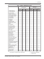
The features of this family of microprocessor-based programmable controllers are
summarized and compared to those of the 1208, 1203A, and 1213 controllers in
Table 1.
Familiarity with your Curtis PMC controller will help you install and operate it
properly. We encourage you to read this manual carefully. If you have questions,
please contact the Curtis office nearest you.
Curtis PMC 1223/33, 1225/35, 1227/37 Manual
3
1 — OVERVIEW
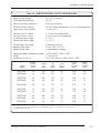
Table 1 MODEL COMPARISON CHART
MultiMode™
Microprocessor-Based Models
Analog Models
Voltage Range (V)
Current Range (A) 1
Current Limited
Regen. Current Limit
Undervoltage Protection
Overvoltage Protection
Pot Adjustable
Programmable
Diagnostics
Full Bridge
Wigwag Throttle
Single-Ended Throttle
HPD
Anti-Rollback
Anti-Roll-Forward
Load Compensation
MultiMode™ Input
Push Too Fast
Push Input
Key Off Deceleration
Brake Output
Inhibit Input
Reverse Beeper
Power Saver
Speed Limit Input
Momentary Input Option
Output Fault Detect
Open Pot Fault
ISO Pot Fault
Temperature Compensation
Temperature Protection
SRO
Brake Light Driver (BLD)
Programmable BLD
Belly Button
BB Check Circuit
Microprocessor
Package Type
1
1208
1203A
1213
1223/33
1225/35
1227/37
12–36
45–55
✓
—
✓
✓
—
—
—
—
✓
—
—
—
—
—
—
—
—
—
✓
✓
—
—
—
—
—
✓
—
—
—
—
—
—
—
—
—
Card
12–36
60–90
✓
✓
✓
✓
✓
—
—
—
✓
✓
✓
—
—
—
—
—
—
—
✓
✓
—
—
—
—
—
✓
—
—
✓
—
—
—
—
—
—
Card
24–48
100–200
✓
✓
✓
✓
✓
—
—
✓
✓
✓
✓
✓
✓
✓
—
✓
—
—
✓
✓
—
—
—
—
—
✓
✓
✓
✓
—
✓
—
—
—
—
ABS cover
24–36
70–110
✓
✓
✓
✓
—
✓
✓
✓
✓
✓
✓
✓
✓
✓
✓
✓
✓
✓
✓2
✓
✓
✓
✓
✓
✓
✓
✓
✓
✓
✓3
—
✓3
✓3
✓3
✓
Card
24–36
90–125
✓
✓
✓
✓
—
✓
✓
✓
✓
✓
✓
✓
✓
✓
✓
✓
✓
✓
✓2
✓
✓
✓
✓
✓
✓
✓
✓
✓
✓
✓3
—
✓3
✓3
✓3
✓
Sealed
24–48
100–200
✓
✓
✓
✓
—
✓
✓
✓
✓
✓
✓
✓
✓
✓
✓
✓
✓
✓
✓2
✓
✓
✓
✓
✓
✓
✓
✓
✓
✓
✓3
—
✓3
✓3
✓3
✓
ABS cover
current depends on voltage and model; maximum listed
Curtis PMC 1223/33, 1225/35, 1227/37 Manual
✓ 2 brake output is programmable
✓ 3 123X series only
4
2 — INSTALLATION & WIRING
2
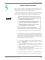
INSTALLATION AND WIRING
Installation and wiring instructions are presented separately for the 1223/33
controllers, 1225/35 controllers, and 1227/37 controllers. The three individual
installation and wiring sections are followed by common sections that cover
throttle wiring, auxiliary driver output options, and switches and other hardware.
☞
CAUTION
Working on electric vehicles is potentially dangerous. You should protect
yourself against runaways, high current arcs, and outgassing from lead acid
batteries:
RUNAWAYS — Some conditions could cause the vehicle to run out of control.
Disconnect the motor or jack up the vehicle and get the drive wheels off the
ground before attempting any work on the motor control circuitry. NOTE: If
the wrong combination of throttle and switch styles is selected with the
handheld programmer, the vehicle may suddenly begin to move.
— Electric vehicle batteries can supply very high
power, and arcs can occur if they are short circuited. Always open the battery
circuit before working on the motor control circuit. Wear safety glasses, and
use properly insulated tools to prevent shorts.
HIGH CURRENT ARCS
LEAD ACID BATTERIES — Charging or discharging generates hydrogen gas,
which can build up in and around the batteries. Follow the battery
manufacturer’s safety recommendations. Wear safety glasses.
Curtis PMC 1223/33, 1225/35, 1227/37 Manual
5
2 — INSTALLATION & WIRING: 1223/33 Controllers
1223/33 CONTROLLERS
1223/33 Installation
The controller can be oriented in any position, but the location should be
carefully chosen to keep the controller clean and dry. If a clean, dry mounting
location cannot be found, a cover must be used to shield the controller from
water and contaminants.
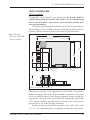
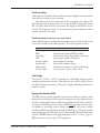
The outline and mounting hole dimensions for the 1223/33 controllers are
shown in Figure 2. The controller can be mounted by the top of the heatsink or
by means of the four mounting holes at the corners of the circuit board.
Fig. 2 Mounting
dimensions, Curtis PMC
1223/33 controllers.
146 (5.75)
138 (5.45)
B+
104
(4.10)
B-
42
(1.65)
96.5
(3.80)
M2
M1
17.1
(0.67)
25.1
(0.99)
25.4
(1.00)
M4 tapped,
4 plcs
3.8 (0.15) dia.,
4 plcs
39
(1.53)
Dimensions in millimeters and (inches)
Mounting the controller via the tapped holes in the heatsink is the preferred
method and requires M4 screws. If the controller is mounted via the circuit
board, care should be taken to ensure that no conductive hardware overlaps the
copper planes at the power connect end of the board. Additionally, at least 6 mm
(1/4") clearance should be provided below the bottom of the circuit board to
prevent shorts to any of the thru-hole connections.
In either case the heatsink should be attached to at least a 100 × 125 × 3 mm
(4" × 5" × 1/8") aluminum plate or its equivalent to obtain the rated currents.
Curtis PMC 1223/33, 1225/35, 1227/37 Manual
6
2 — INSTALLATION & WIRING: 1223/33 Controllers
Although not usually necessary, a thermal joint compound can be used to
improve heat conduction from the heatsink to the mounting surface.
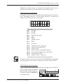
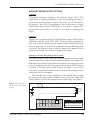
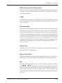
1223/33 Low Current Connections
A 16-pin low current connector provides the low current logic control connections. The mating connector is a 16-pin Molex Mini-Fit Jr. connector part
number 39-01-2165 using type 5556 terminals.
16
15
14
13
12
11
10
9
8
7
6
5
4
3
2
1
Pin 1
Pin 2
Pin 3
Pin 4
Pin 5
Pin 6
Pin 7
Pin 8
pot high
pot wiper
pot low
speed limit pot wiper
push
inhibit
program 1 driver
brake +
Pin 9
Pin 10
Pin 11
Pin 12
Pin 13
Pin 14
Pin 15
Pin 16
horn driver
emergency reverse (1233 only)
mode switch and LED driver
forward switch
direction/reverse switch and LED driver
power enable switch and Status LED driver
keyswitch input (KSI)
program 2 driver (1233 only)
A 4-pin low power connector is provided for the handheld 1307 programmer.
The mating cable can be ordered as a separate part: Curtis PMC p/n 16185.
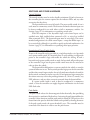
1223/33 High Current Connections
Ten 1/4" quick-connect terminals are provided for the high current connections.
Three terminals each are provided for
the battery B+ and B- connections.
The motor connections (M1, M2) have
M1
M2
BB+
two terminals each.
Curtis PMC 1223/33, 1225/35, 1227/37 Manual
7
2 — INSTALLATION & WIRING: 1223/33 Controllers
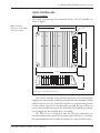
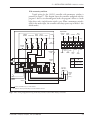
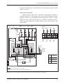
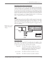
1223/33 Wiring Configurations
The 1223/33 controller can be configured to work with either on/off or momentary switches for selecting direction and mode. If a power enable switch is used,
it must be momentary style. For more information on control switches, see p. 24.
With on/off switches
Typical wiring for the 1223/33 controller with on/off switches is presented in
Figure 3. This diagram shows the controller configured with the program 1 driver
as an electromagnetic brake, the program 2 driver as a brake light driver, and two
SPST switches used for selecting direction. NOTE: In the configuration shown, the
power enable pin is an output that drives the Status LED. With on/off switches,
the power enable function is performed by the keyswitch and a power enable
switch is not used.
CONTROL
FUSE
KEY
SWITCH
REV
PUSH
FWD
MULTI
MODE
BELLY
BUTTON
16-pin detail:
HORN
PROGRAM 2
DRIVER
POWER
ENABLE
DIRECTION/
REVERSE
KSI
R
MULTI
MODE
HORN
H
BRAKE
LIGHT
16
15
14
13
12
11
10
9
8
7
6
5
4
3
2
1
POWER
FUSE
PROGRAM 1
DRIVER
B+
BRAKE +
B+
INHIBIT
B-
B-
BELLY
BUTTON
FORWARD
M2
A
POT LO
PUSH
SPEED
LIMIT
POT HI
POT
WIPER
Battery
Voltage
R
24V
1.5 kΩ, 0.5 W
36V
2.4 kΩ, 1 W
5 kΩ POT
THROTTLE
M1
SPEED
LIMIT
POT
(100 kΩ)
*
BRAKE
INHIBIT
feature available only on 1233 models
*
optional switch operated by mechanical brake release
Fig. 3 Basic wiring configuration using on/off switches, Curtis PMC 1223/33 controller.
Curtis PMC 1223/33, 1225/35, 1227/37 Manual
8
2 — INSTALLATION & WIRING: 1223/33 Controllers
With momentary switches
Typical wiring for the 1223/33 controller with momentary switches is presented
in Figure 4. This diagram shows the controller configured with the program 1
driver as an electromagnetic brake, the program 2 driver as a brake light driver,
and a single direction switch. NOTE: When a momentary switch is used for the
mode input, the controller will always power up in Mode 1 (the default mode).
CONTROL
FUSE
KEY
SWITCH
PUSH
POWER
ENABLE
DIRECTION
MULTI
MODE
BELLY
BUTTON
16-pin detail:
HORN
PROGRAM 2
DRIVER
POWER
ENABLE
DIRECTION/
REVERSE
KSI
R
R
BRAKE
LIGHT
POWER
FUSE
R
15
14
13
12
11
10
9
8
7
6
5
4
3
2
1
PUSH
INHIBIT
B-
B-
M2
A
HORN
16
BRAKE +
B+
MULTI
MODE
H
PROGRAM 1
DRIVER
B+
BELLY
BUTTON
FORWARD
POT LO
SPEED
LIMIT
POT HI
POT
WIPER
Battery
Voltage
R
24V
1.5 kΩ, 0.5 W
36V
2.4 kΩ, 1 W
5 kΩ POT
THROTTLE
M1
SPEED
LIMIT
POT
(100 kΩ)
*
BRAKE
INHIBIT
feature available only on 1233 models
*
optional switch operated by mechanical brake release
Fig. 4 Basic wiring configuration using momentary switches, Curtis PMC 1223/33 controller.
Curtis PMC 1223/33, 1225/35, 1227/37 Manual
9
2 — INSTALLATION & WIRING: 1225/35 Controllers
1225/35 CONTROLLERS
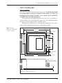
1225/35 Installation
The outline and mounting hole dimensions for the 1225/35 controllers are
shown in Figure 5.
Fig. 5 Mounting
dimensions, Curtis PMC
1225/35 controllers.
148 (5.83)
4.57 (0.180) dia.,
4 plcs
116
(4.58)
127
(5.0)
159 (6.25)
48
(1.88)
Dimensions in millimeters and (inches)
The 1225/35 controller can be oriented in any position. To ensure full rated
output power, the controller should be positioned so that the maximum available
airflow travels across its ribs. Fasten the controller to a secure mounting bracket
or other surface, using the four mounting holes provided. Be sure to allow easy
access to the controller’s connection face so that the 1307 handheld programmer
can be plugged into the controller after it is installed.
The 1225/35 case is designed to meet the IP54 seal requirements for
environmental protection against dust and water splash. However, it is nevertheless recommended that the controller be mounted in a clean and dry location.
Curtis PMC 1223/33, 1225/35, 1227/37 Manual
10
2 — INSTALLATION & WIRING: 1225/35 Controllers
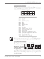
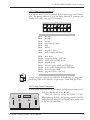
1225/35 Low Current Connections
A 16-pin low current connector provides the low current logic control connections. The mating connector is a 16-pin Molex Mini-Fit Jr. connector part
number 39-01-2165 using type 5556 terminals.
16
15
14
13
12
11
10
9
8
7
6
5
4
3
2
1
Pin 1
Pin 2
Pin 3
Pin 4
Pin 5
Pin 6
Pin 7
Pin 8
pot high
pot wiper
pot low
speed limit pot wiper
push
inhibit
program 1 driver
brake +
Pin 9
Pin 10
Pin 11
Pin 12
Pin 13
Pin 14
Pin 15
Pin 16
horn driver
emergency reverse (1235 only)
mode switch and LED driver
forward switch
direction/reverse switch and LED driver
power enable switch and Status LED driver
keyswitch input (KSI)
program 2 driver (1235 only)
A 4-pin low power connector is provided for the handheld 1307 programmer.
The mating cable can be ordered as a separate part: Curtis PMC p/n 16185.
1225/35 High Current Connections
Ten 1/4" quick-connect terminals are provided for the high current connections.
Three terminals each are proM2
M1
vided for the battery B+ and
BB- connections. The motor
B+
connections (M1, M2) have
two terminals each.
Mating connectors are available. The 3-terminal battery connectors are
Curtis PMC p/n 16551, and the 2-terminal motor connectors are p/n 16552.
Both connectors use Curtis PMC p/n 16553 terminal pins designed for use with
#10 AWG (2.59 mm).
Curtis PMC 1223/33, 1225/35, 1227/37 Manual
11
2 — INSTALLATION & WIRING: 1225/35 Controllers
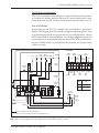
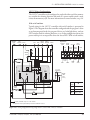
1225/35 Wiring Configurations
The 1225/35 controller can be configured to work with either on/off or momentary switches for selecting direction and mode. If a power enable switch is used,
it must be momentary style. For more information on control switches, see p. 24.
With on/off switches
Typical wiring for the 1225/35 controller with on/off switches is presented in
Figure 6. This diagram shows the controller configured with the program 1 driver
as an electromagnetic brake, the program 2 driver as a brake light driver, and two
SPST switches used for selecting direction. NOTE: In the configuration shown, the
power enable pin is an output that drives the Status LED. With on/off switches,
the power enable function is performed by the keyswitch and a power enable
switch is not used.
16-pin detail:
REV
FWD
MULTI
MODE
BELLY
BUTTON HORN
PROGRAM 2
DRIVER
PUSH
POWER
ENABLE
DIRECTION/
REVERSE
KSI
R
H
KEY
SWITCH
BRAKE
LIGHT
M2
M1
14
13
12
11
10
9
8
7
6
5
4
3
2
1
BRAKE +
B+
POT LO
PUSH
INHIBIT
B+
B-
HORN
15
POWER
FUSE
A
MULTI
MODE
16
PROGRAM 1
DRIVER
CONTROL
FUSE
BELLY
BUTTON
FORWARD
SPEED
LIMIT
POT HI
POT
WIPER
Battery
Voltage
R
24V
1.5 kΩ, 0.5 W
36V
2.4 kΩ, 1 W
5 kΩ POT
THROTTLE
B-
*
SPEED
LIMIT
POT
(100 kΩ)
BRAKE
INHIBIT
feature available only on 1235 models
*
optional switch operated by mechanical brake release
Fig. 6 Basic wiring configuration using on/off switches, Curtis PMC 1225/35 controller.
Curtis PMC 1223/33, 1225/35, 1227/37 Manual
12
2 — INSTALLATION & WIRING: 1225/35 Controllers
With momentary switches
Typical wiring for the 1225/35 controller with momentary switches is
presented in Figure 7. This diagram shows the controller configured with the
program 1 driver as an electromagnetic brake, the program 2 driver as a brake
light driver, and a single direction switch. NOTE: When a momentary switch is
used for the mode input, the controller will always power up in Mode 1 (the
default mode).
16-pin detail:
POWER
ENABLE
DIRECTION
MULTI
MODE
BELLY
BUTTON
HORN
PROGRAM 2
DRIVER
PUSH
POWER
ENABLE
DIRECTION/
REVERSE
KSI
R
R
R
H
KEY
SWITCH
BRAKE
LIGHT
M2
M1
14
13
12
11
10
9
8
7
6
5
4
3
2
1
BRAKE +
B+
B-
B+
HORN
15
POWER
FUSE
A
MULTI
MODE
16
PROGRAM 1
DRIVER
CONTROL
FUSE
BELLY
BUTTON
FORWARD
POT LO
PUSH
INHIBIT
SPEED
LIMIT
POT HI
POT
WIPER
Battery
Voltage
R
24V
1.5 kΩ, 0.5 W
36V
2.4 kΩ, 1 W
5 kΩ POT
THROTTLE
B-
*
SPEED
LIMIT
POT
(100 kΩ)
BRAKE
INHIBIT
feature available only on 1235 models
*
optional switch operated by mechanical brake release
Fig. 7 Basic wiring configuration using momentary switches, Curtis PMC 1225/35 controller.
Curtis PMC 1223/33, 1225/35, 1227/37 Manual
13
2 — INSTALLATION & WIRING: 1227/37 Controllers
1227/37 CONTROLLERS
1227/37 Installation
The 1227/37 controller can be mounted in any position, but the location should
be carefully chosen to keep the controller clean and dry. If a clean, dry
mounting location cannot be found, a cover must be used to shield the
controller from water and contaminants.
The outline and mounting hole dimensions for the 1227/37 controllers are
shown in Figure 8. To ensure full rated output power, the controller should be
fastened to a clean, flat metal surface with three screws.
Although not usually necessary, a thermal joint compound can be used to
improve heat conduction from the case to the mounting surface.
Fig. 8 Mounting
dimensions, Curtis PMC
1227/37 controllers.
165 (6.50)
127 (5.00)
22 (0.85)
28 (1.1)
Status LED
122
(4.80)
66 (2.6)
CL
6.7 (0.265) dia.,
3 plcs
152 (6.00)
6.3 (0.25)
21 × 16 × 1.5
(0.83 × 0.63 × 0.06);
8.4 (0.33) dia. hole thru
65
(2.56)
4.8 (0.19)
Dimensions in millimeters and (inches)
Curtis PMC 1223/33, 1225/35, 1227/37 Manual
14
2 — INSTALLATION & WIRING: 1227/37 Controllers
1227/37 Low Current Connections
A 16-pin low current connector provides the low current logic control connections. The mating connector is a 16-pin Molex Mini-Fit Jr. connector part
number 39-01-2165 using type 5556 terminals.
16
15
14
13
12
11
10
9
8
7
6
5
4
3
2
1
Pin 1
Pin 2
Pin 3
Pin 4
Pin 5
Pin 6
Pin 7
Pin 8
pot high
pot wiper
pot low
speed limit pot wiper
push
inhibit
program 1 driver
main contactor coil driver
Pin 9
Pin 10
Pin 11
Pin 12
Pin 13
Pin 14
Pin 15
Pin 16
horn driver
emergency reverse (1237 only)
mode switch and LED driver
forward switch
direction/reverse switch and LED driver
power enable switch and Status LED driver
keyswitch input (KSI)
program 2 driver (1237 only)
A 4-pin low power connector is provided for the handheld 1307 programmer.
The mating cable can be ordered as a separate part: Curtis PMC p/n 16185.
1227/37 High Current Connections
MB-
Four tin-plated copper bus bars are provided for the high current connections to
the battery (B-, B+) and motor (M-, A2).
Cables are fastened to the bus bars by M8 (5⁄16") bolts.
When tightening the bolts, two opposing wrenches should be
A2
used to prevent bending the bus bars and putting undue strain
B+
on the internal connections.
Curtis PMC 1223/33, 1225/35, 1227/37 Manual
15
2 — INSTALLATION & WIRING: 1227/37 Controllers
1227/37 Wiring Configurations
The 1227/37 controller can be configured to work with either on/off or momentary switches for selecting direction and mode. If a power enable switch is used,
it must be momentary style. For more information on control switches, see p. 24.
With on/off switches
Typical wiring for the 1227/37 controller with on/off switches is presented in
Figure 9. This diagram shows the controller configured with the program 1 driver
as an electromagnetic brake, the program 2 driver as a brake light driver, and two
SPST switches used for selecting direction. NOTE: In the configuration shown, the
power enable pin is an output that drives the Status LED. With on/off switches,
CONTROL
FUSE
KEY
SWITCH PUSH
REV
FWD
MULTI
MODE
BELLY
BUTTON
HORN
16-pin detail:
PROGRAM 2
DRIVER
POWER
ENABLE
DIRECTION/
REVERSE
KSI
R
HORN
16
15
14
13
12
11
10
9
8
7
6
5
4
3
2
1
PROGRAM 1
DRIVER
MAIN
MAIN
BRAKE
M-
INHIBIT
POT LO
PUSH
SPEED
LIMIT
POT HI
POT
WIPER
5 kΩ POT
THROTTLE
A2
B-
SPEED
LIMIT
POT
(100 kΩ)
B+
INHIBIT
POWER
FUSE
B+
MULTI
MODE
H
BRAKE
LIGHT
*
BELLY
BUTTON
FORWARD
MAIN
A
Battery
Voltage
R
24V
1.5 kΩ, 0.5 W
36V
2.4 kΩ, 1 W
48V
3.2 kΩ, 2 W
B-
feature available only on 1237 models
*
optional switch operated by mechanical brake release
Fig. 9 Basic wiring configuration using on/off switches, Curtis PMC 1227/37 controller.
Curtis PMC 1223/33, 1225/35, 1227/37 Manual
16
2 — INSTALLATION & WIRING: 1227/37 Controllers
the power enable function is performed by the keyswitch and a power enable
switch is not used.
With momentary switches
Typical wiring for the 1227/37 controller with momentary switches is
presented in Figure 10. This diagram shows the controller configured with the
program 1 driver as an electromagnetic brake, the program 2 driver as a brake
light driver, and a single direction switch. NOTE: When a momentary switch is
used for the mode input, the controller will always power up in Mode 1 (the
default mode).
CONTROL
FUSE
KEY
SWITCH PUSH
POWER
ENABLE
DIRECTION
MULTI
MODE
BELLY
BUTTON
HORN
16-pin detail:
PROGRAM 2
DRIVER
POWER
ENABLE
DIRECTION/
REVERSE
KSI
R
R
R
15
14
13
12
11
10
9
8
7
6
5
4
3
2
1
MAIN
BRAKE
INHIBIT
SPEED
LIMIT
POT HI
POT
WIPER
SPEED
LIMIT
POT
(100 kΩ)
B+
INHIBIT
POWER
FUSE
B+
POT LO
PUSH
5 kΩ POT
THROTTLE
A2
B-
HORN
16
PROGRAM 1
DRIVER
MAIN
M-
MULTI
MODE
H
BRAKE
LIGHT
*
BELLY
BUTTON
FORWARD
MAIN
A
Battery
Voltage
R
24V
1.5 kΩ, 0.5 W
36V
2.4 kΩ, 1 W
48V
3.2 kΩ, 2 W
B-
*
feature available only on 1237 models
optional switch operated by mechanical brake release
Fig. 10 Basic wiring configuration using momentary switches, Curtis PMC 1227/37 controller.
Curtis PMC 1223/33, 1225/35, 1227/37 Manual
17
2 — INSTALLATION & WIRING: Throttle
THROTTLE WIRING
The 1223/33, 1225/35, and 1227/37 controllers are programmable to suit a
variety of throttles. If the throttle you are planning to use is not covered, contact
the Curtis office nearest you.
Mounting dimensions are provided in Appendix B for the standard 5kΩ,
3-wire throttle potentiometer (manufactured for Curtis PMC by Clarostat), the
Curtis PMC potboxes and footpedals, and the electronic throttle ET-1XX
(manufactured for Curtis by Hardellet).
For information on programming various throttle parameters, see Section 3:
Programmable Parameters; the throttle parameters are on pages 33–39.
5kΩ, 3-Wire Potentiometer
A 5kΩ, 3-wire potentiometer is the standard throttle, and is shown in the basic
wiring diagrams (Figures 3 & 4, 6 & 7, and 9 & 10). The controller can be
programmed to be compatible with single-ended, wigwag, or inverted wigwag
style throttles (see page 33). These throttle styles are defined in Table 2 (page 19).
NOTE: The standard 8% neutral deadband and 100% throttle gain are assumed
in the definitions; resistance is measured between pot low and pot wiper.
For wigwag and inverted wigwag applications, the pot can be correctly
centered within the controller’s neutral band by using the throttle autocalibration
feature (see page 35). Pots with less than 5 kΩ total resistance change over the
throttle’s full stroke can be accommodated by programming the controller for
reduced-range throttle inputs, via the throttle gain parameter (see page 37).
The controller provides full pot fault protection against open or shorted
wires anywhere in the throttle assembly. The overall pot resistance can range
from 4.5 kΩ to 7.0 kΩ. Values outside this range will trigger a fault condition.
If a pot fault occurs while the vehicle is moving, the controller will decelerate the
vehicle to neutral through its normal deceleration curve. If the fault is corrected
while the throttle is still applied, the vehicle will accelerate to the requested speed.
0–5V Throttle
A 0–5V throttle input can be used instead of a pot, as shown in Figure 11. The
controller can be programmed to be compatible with single-ended, wigwag, or
inverted wigwag style throttles (see page 33). These throttle styles are defined in
Table 2 (page 19). With a wigwag or inverted wigwag 0–5V input, the throttle
output voltage must be 2.5 V (± deadband) in neutral and a 4.7kΩ, 0.25W
resistor must be added between the pot high and pot low pins. A resistor is not
required with a single-ended 0–5V input.
Voltage throttles with less than 5 V total voltage change over the full stroke
can be accommodated by programming the controller for reduced-range throttle
inputs, via the throttle gain parameter (see page 37).
Curtis PMC 1223/33, 1225/35, 1227/37 Manual
18
2 — INSTALLATION & WIRING: Throttle
Fig. 11 Wiring for 0–5V
throttle.
16
15
14
13
12
11
10
9
8
7
6
5
4
3
2
1
+
4.7kΩ, 0.25W
-
B-
PIN KEY
required with wigwag throttles
Pin 3 Pot Low Input
Pin 2 0–5V Input
Pin 1 Pot High Input
Because the throttle input voltage is referenced to B- and no throttle
connections are made to the pot high and pot low inputs, throttle fault protection is lost with 0–5V throttles. The only throttle fault that will be detected by
the controller is a broken wire to the pot wiper input (Pin 2), which will cause a
normal deceleration to zero speed. The controller will not recognize out-of-range
throttle inputs as faults, and applying excessive voltages to the throttle wiper
input may damage the controller. It is the responsibility of the vehicle
manufacturer to provide throttle fault detection for 0–5V throttles.
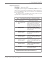
Table 2 THROTTLE STYLES for 3-wire, 5kΩ pots (0–5V throttles)
THROTTLE STYLE
DESCRIPTION OF OPERATION
Single-Ended
Zero speed at any resistance less than 400 Ω (0.4 V).
Controller output increases as resistance increases in
the selected direction. Maximum output is reached at
4.8 kΩ (4.8 V).
Wigwag
Zero speed at 2.5 kΩ ±200 Ω (2.5 V ±0.2 V). Controller
output increases in the forward direction as resistance
increases, with maximum forward output reached at
4.8 kΩ (4.8 V). Output increases in the reverse
direction as this resistance decreases, with maximum
reverse output reached at 200 Ω (0.2 V).
Inverted Wigwag
Same as wigwag, with the exception that increasing
the resistance increases controller output in the
reverse direction, and decreasing resistance increases
output in the forward direction.
Curtis PMC 1223/33, 1225/35, 1227/37 Manual
19
2 — INSTALLATION & WIRING: Throttle
Curtis ET-XXX Electronic Throttle
The recommended wiring for the Curtis ET-XXX electronic throttle is shown in
Figure 12. The ET-XXX throttle provides a single-ended 0–5V throttle signal and
a signal indicating whether it is in forward or reverse. If the controller is
configured to require only a single direction switch, only the reverse output wire
(white wire) needs to be connected. If the controller is configured to require
separate inputs for forward and reverse, the forward output wire (black/white
wire) must also be connected. NOTE: The controller must be programmed as a
single-ended 0–5V throttle type for use with the ET-XXX.
As with any 0–5V throttle, there is no fault detection built into the ET-XXX.
It is the responsibility of the vehicle manufacturer to provide throttle fault
detection when using the ET-XXX.
Fig. 12 Wiring for Curtis
B+
ET-XXX electronic throttle.
KEYSWITCH
16
15
14
13
12
11
10
9
8
7
6
5
4
3
2
1
WHT/
GRN
PIN KEY
WHT/BRN
BGREEN
Pin 2
ORANGE
BLACK
Pin 15 KSI Input
Pin 13 Direction/Reverse
Pin 12 Forward
0–5V Input
B-
BLACK/WHITE
WHITE
connector
only for controllers that require separate inputs
for forward and reverse (Direction Input Type “2”)
Curtis PMC 1223/33, 1225/35, 1227/37 Manual
20
2 — INSTALLATION & WIRING: Throttle
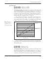
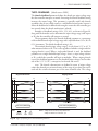
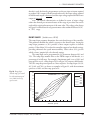
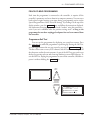
Speed Limit Pot
A speed limit pot allows the operator to adjust the speed of the vehicle at full
throttle. Wiring for the speed limit pot is shown in each of the basic wiring
diagrams (Figures 3 & 4, 6 & 7, 9 & 10). The speed limit pot should be sized so
that it does not affect the throttle input resistance and thus the throttle response.
A 100kΩ pot is recommended.
The speed limit pot is at its maximum speed setting when its wiper is shorted
to the throttle pot’s pot high connection (Pin 1). When the speed limit pot is in
its maximum speed position, the vehicle’s speed at full throttle corresponds to the
programmed maximum speed setting. The speed limit pot is at its minimum
speed setting when its wiper is shorted to the throttle pot’s pot low connection
(Pin 3). When the speed limit pot is in its minimum speed position, the vehicle’s
speed at full throttle corresponds to the programmed minimum speed setting.
For information on the programmable speed parameters, see Section 3.
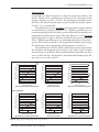
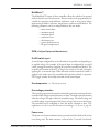
The speed limit pot varies the vehicle’s speed linearly over the range between
the minimum and maximum speed settings in each mode. In the examples
shown in Figure 13, the Mode 2 maximum and minimum speeds (M2 max, min)
are set at 100% and 40%, and the Mode 1 maximum and minimum speeds (M1
max, min) are set at 60% and 20%.
MODE 2 OPERATION
80
70
60
50
M2
min
40
30
20
M2
max
100
PWM OUTPUT (percent)
PWM OUTPUT (percent)
90
10
90
80
70
60
50
M2
min
40
30
20
10
0
50
100
90
80
70
60
50
M2
min
40
30
20
10
0
0
M2
max
100
PWM OUTPUT (percent)
M2
max
100
0
0
50
100
0
50
100
THROTTLE (percent)
THROTTLE (percent)
THROTTLE (percent)
Speed limit pot in maximum speed position
Speed limit pot halfway
Speed limit pot in minimum speed position
100
100
90
90
90
80
70
M1
max
60
50
40
30
M1
min
20
10
80
70
M1
max
60
50
40
30
M1
min
20
10
0
50
100
80
70
M1
max
60
50
40
30
M1
min
20
10
0
0
PWM OUTPUT (percent)
100
PWM OUTPUT (percent)
PWM OUTPUT (percent)
MODE 1 OPERATION
0
0
50
100
0
50
100
THROTTLE (percent)
THROTTLE (percent)
THROTTLE (percent)
Speed limit pot in maximum speed position
Speed limit pot halfway
Speed limit pot in minimum speed position
Fig. 13 Effect of speed limit pot position on speed curves.
Curtis PMC 1223/33, 1225/35, 1227/37 Manual
21
2 — INSTALLATION & WIRING: Throttle
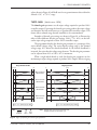
The speed limit pot also limits the vehicle’s reverse speed. Reverse speed is
linearly proportional to the speed limit pot setting and is adjustable from the
Mode 1 minimum speed (speed limit pot in its minimum speed position) to the
programmed maximum reverse speed (speed limit pot in its maximum speed
position).
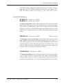
If a speed limit pot is not used, the speed limit input (Pin 4) can be jumpered
to the pot high input, as shown in Figure 14. In this configuration, the vehicle
speed at full throttle is defined by the programmed maximum speed. If no
jumper is used, the vehicle speed at full throttle will be limited to the programmed minimum speed, which by default will also apply to reverse.
Fig. 14 Wiring of speed
limit input to enable
maximum speed when no
speed limit pot is used.
16
15
14
13
12
11
10
9
8
7
6
5
4
3
2
1
JUMPER
PIN KEY
Pin 4
Pin 1
Speed Limit Pot Wiper
Pot High Input
If a speed limit pot will never be used in the application, the controller can
be factory-configured without the speed limit feature (see Section 4), and the
jumper will not be required. With such a controller, the vehicle speed at full
throttle is defined by the programmed maximum speed, and it is possible to
program the reverse speed to a lower value if so desired.
Curtis PMC 1223/33, 1225/35, 1227/37 Manual
22
2 — INSTALLATION & WIRING: Auxiliary Drivers
AUXILIARY DRIVER OUTPUT OPTIONS
Program 1
The program 1 parameter configures a low side driver output at Pin 7. This
output driver is typically programmed to drive an electromagnetic brake (as
shown in the basic wiring diagrams (Figures 3 & 4, 6 & 7, 9 & 10). Alternatively,
the program 1 driver can be programmed to drive an hour meter, sweeper/
scrubber brush motor contactor, brake light, etc. It is rated at 1 ampere and is
protected from external shorts. See Section 3 for details on configuring this
output.
Program 2
The program 2 parameter configures a high side driver output at Pin 16 on the
123X-series controllers (1233, 1235, 1237). This driver can be programmed to
drive an hour meter, belly button check output, sweeper/scrubber brush motor
contactor, brake light, etc. It can also be configured to perform a BB wiring check
(see below). The program 2 driver is rated at 2 amperes and is not short circuit
protected. See Section 3 for details on configuring this output.
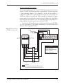
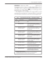
Emergency Reverse (Belly Button) Wiring Check
The 123X controllers (1233, 1235, 1237) can be configured to perform a check
on the emergency reverse input wiring by using the program 2 driver output. This
check allows the controller to determine the continuity of the emergency reverse
wiring. To implement this check, the program 2 driver output (Pin 16) must be
connected to the belly button switch as shown in Figure 15. NOTE: If the
connection is not made at the belly button switch as shown, the emergency reverse
wiring check will not be complete.
The controller can be factory-configured to either inhibit driving or limit
the driving speed to the specified emergency reverse speed if the wiring check
circuitry detects a break in the emergency reverse input wiring; see Section 4.
Fig. 15 Wiring to check
KEYSWITCH
the emergency reverse input
wiring.
BELLY
BUTTON
SWITCH
B-
16
15
14
13
12
11
10
9
PIN KEY
8
7
6
5
4
3
2
1
Pin 16 Program 2 Driver
Pin 10 Emerg. Reverse
Curtis PMC 1223/33, 1225/35, 1227/37 Manual
23
2 — INSTALLATION & WIRING: Switches, etc.
SWITCHES AND OTHER HARDWARE
Control Switches
The control switches must be sized to handle a minimum 150 mA of current to
the controller plus the current required for the indicator LEDs and any other
accessories that they drive.
The keyswitch must be an on/off switch. The power enable switch, if one is
used, must be a momentary switch. The direction and mode selection inputs can
be factory-configured for use with either on/off or momentary switches. See
Section 4, page 47, for information on specifying switch styles.
With the exception of the keyswitch input, each control input can be
specified active high (enabled when connected to B+) or active low (enabled
when connected to B-). The keyswitch input must be active high. The recommended configuration is for all the control inputs—except the inhibit input—to
be set active high, although it is possible to specify any desired combination. See
Section 4, page 47, for information on specifying these input polarities.
Keyswitch and Power Enable Switch
Power to the controller can be provided via a single keyswitch or via a keyswitch
and a power enable switch. If a keyswitch alone is used, enabling it will provide
power to the controller’s logic and enable the vehicle for driving. If both a
keyswitch and a power enable switch are used, the keyswitch will provide power
to the controller’s logic but the power enable switch must also be activated in
order to drive the vehicle.
The keyswitch should function as a master switch for the vehicle, to turn the
system off when not in use. The keyswitch provides logic power for the controller
and the other control input switches. An on/off switch must therefore be used for
the keyswitch, and must be sized to carry the 150 mA quiescent logic current plus
the current necessary to drive the precharge function (0.5 A for 0.5 seconds), any
LED indicators, and any other accessories powered from the keyswitch line.
If a power enable switch is used, it must be configured as a momentary
switch, so that the controller can supply diagnostic information via the Status
LED flash codes.
Push Switch
The push switch releases the electromagnetic brake electrically, thus precluding
the necessity for a mechanical brake release. Activating the push input inhibits the
controller’s drive functions until the push switch is turned off. The push-too-fast
feature limits the speed at which the vehicle can be pushed by shorting the motor
if the push speed exceeds the preset threshold. NOTE: The controller must be
connected to the batteries in order to use the push feature.
Curtis PMC 1223/33, 1225/35, 1227/37 Manual
24
2 — INSTALLATION & WIRING: Switches, etc.
Brake Release Switch (Brake Coil Disable Switch)
If a brake release lever is used to release the electromagnetic brake mechanically,
a brake coil disable switch is recommended. This switch opens the electromagnetic brake coil when the mechanical brake release lever releases the brake from
the motor shaft. The open brake coil will register as a fault, inhibiting controller
operation if an operator attempts to drive the vehicle with the brake mechanically
released. This safety feature ensures that the vehicle cannot be driven when the
brake cannot be engaged. NOTE: A brake coil disable switch—or a self-resetting
brake—is required to conform with TÜV regulations.
Inhibit
The inhibit input can be used to inhibit controller operation for any reason.
Typically it is used during battery charging, as shown in Figure 16. The inhibit
input overrides all other controller inputs and is active when low (i.e., when
within 1.0 V of B-). The input can be left floating when not engaged; it does not
need to be pulled high.
Fig. 16 Wiring to inhibit
operation during battery
charging.
to controller BB-
to controller B+
16
15
14
13
12
11
10
9
8
7
6
5
4
3
2
1
B+
POWER
FUSE
PIN KEY
Pin 6
+
Inhibit
-
BATTERY
CHARGER
Panel Indicator LEDs
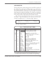
The 1223/33, 1225/35, and 1227/37 controllers have the capability to drive
indicator LEDs. These LEDs can be used as panel indicators to tell the operator,
at a glance, the status, direction, and mode of the controller.
Status LED — This LED always indicates whether the controller is
powered on or off. The Status LED will also provide
diagnostics information via flash codes. See Section 7
for Status LED operation and fault codes.
Direction LED — This LED is lit when the controller is in reverse.
Mode LED — This LED is lit when the controller is in Mode 1.
Curtis PMC 1223/33, 1225/35, 1227/37 Manual
25
2 — INSTALLATION & WIRING: Switches, etc.
If momentary switches are being used, the controller will drive the LEDs
from an internal source. If on/off switches are used, the Direction LED and
Mode Indicator LED are powered directly from the switches and only the Status
LED is driven by the controller.
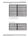
If indicator LEDs are used, they should be installed with the proper resistors
in series. The controller’s LED drivers are capable of providing a maximum
current of 30 mA. The recommended resistors — designed to limit driver current
to 15 mA when active — are listed in Table 3.
Table 3 RESISTORS FOR INDICATOR LEDs
VOLTAGE
RESISTOR
VALUE
POWER
RATING
24V
1.5 kΩ
0.5 W
36V
2.4 kΩ
1.0 W
48V
3.3 kΩ
2.0 W
Horn
The controller’s horn driver — Pin 9 — is designed to drive a piezoelectric horn.
The horn sounds a warning when the reverse direction is selected (a series of beep
tones) and when the throttle autocalibration feature is being used (a constant
tone).
The horn driver provides a maximum current of 30 mA. Using a horn with
a higher current requirement will damage and disable the driver.
Main Contactor
An external main contactor is required with the 1227/37 controllers, and is shown
in their wiring diagrams (Figures 9 and 10). A heavy-duty single-pole, singlethrow (SPST) contactor with silver-alloy contacts is recommended, such as an
Albright SW80 or SW180. This contactor does not require an external precharge
resistor, because of the controllers’ built-in precharging feature.
Circuitry Protection Devices
To protect the control wiring from accidental shorts, a low current fuse (appropriately sized for the maximum control circuit current draw) should be connected
in series with the battery feed. A fuse is also recommended for use in the high
power connection from the battery to the controller’s B+ terminal. This fuse will
protect the power system from external shorts and should be sized appropriately
for the maximum rated current of the controller.
Curtis PMC 1223/33, 1225/35, 1227/37 Manual
26
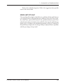
3 — PROGRAMMABLE PARAMETERS
3
PROGRAMMABLE PARAMETERS
The 1223/33, 1225/35, and 1227/37 controllers have a number of parameters
that can be programmed by means of a 1307 handheld programmer. These
programmable parameters allow the vehicle’s performance characteristics to be
customized to fit the needs of individual vehicle operators.
Each controller is shipped with the parameter settings specified by the
OEM. For each programmable parameter, the specification process includes
designating whether it is to have User or OEM-only access rights. In consultation
with Curtis PMC applications engineers, the OEM specifies which—if any—
parameters the user (dealer, distributor, etc.) will be able to adjust. Accordingly,
Curtis PMC offers two versions of the 1307 programmer: the 1307-1101 is the
User programmer (which can adjust only those parameters with User access
rights) and the 1307-2101 is the OEM programmer (which can adjust all the
programmable parameters).
The MultiMode™ feature of these controllers allows operation in two
distinct modes: “Mode 1” and “Mode 2.” These modes can be programmed to
provide two different sets of operating characteristics, which can be useful for
operation in different conditions. For example, a mobility aid scooter might have
Mode 1 programmed such that the vehicle moves slowly for precise, indoor
maneuvering and Mode 2 programmed for higher speed, long distance travel
outdoors.
Seven parameters can be configured independently in the two modes:
—
—
—
—
—
—
—
acceleration rate (M1, M2)
forward deceleration rate (M1, M2)
reverse deceleration rate (M1, M2)
maximum speed (M1, M2)
minimum speed (M1, M2)
IR speed compensation (M1, M2)
main current limit (M1, M2).
If a momentary switch is used to change modes, the controller defaults to
Mode 1 when power is first applied. If an indicator LED is used with the
momentary switch, it will be lit when the controller is in Mode 1.
If an on/off switch is used to change modes, the switch position determines
the mode in which the controller powers up. The controller is in Mode 2 when
the mode input is connected to B+ with the on/off switch type configured.
Leaving the mode input floating or actively pulling it to B- puts the controller in
Mode 1.
Controllers can be factory-set to allow only one mode of operation if a
MultiMode™ system is not desirable for the application—see Section 4.
Curtis PMC 1223/33, 1225/35, 1227/37 Manual
27
3 — PROGRAMMABLE PARAMETERS
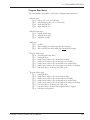
The programmable parameters are described in the following order. They
are listed in the text by the abbreviated names that appear in the programmer’s
Program Menu. Not all of these parameters are displayed on all controllers; the
list for any given controller depends on its specifications.
Acceleration/Deceleration Parameters
Acceleration Rate, M1/M2
Forward Deceleration Rate, M1/M2
Reverse Deceleration Rate, M1/M2
Speed Parameters
Maximum Speed, M1/M2
Minimum Speed, M1/M2
Reverse Speed
Creep Speed
Emergency Reverse Speed
Throttle Parameters
Throttle Type
Direction Change Input Type
Throttle Autocalibration
Throttle Deadband
Throttle Gain
Ramp Shape (Static Throttle Map)
Current Limit Parameters
Main Current Limit, M1/M2
Emergency Reverse Current Limit
Calibration 5: Regen Current Limit Boost
Output Driver Parameters
Program 1 Auxiliary Driver
Program 2 Auxiliary Driver
Program 4: Brake Holding Voltage
Fault Parameters
High Pedal Disable (HPD)
Static Return to Off (SRO)
Other Parameters
IR Compensation, M1/M2
Calibration 4: IR Stiffness
Curtis PMC 1223/33, 1225/35, 1227/37 Manual
28
3 — PROGRAMMABLE PARAMETERS
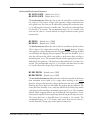
Acceleration/Deceleration Parameters
M1 ACCEL RATE [default access: User]
M2 ACCEL RATE [default access: User]
The acceleration rate defines the time it takes the controller to accelerate from
0% output to 100% output. A larger value represents a longer acceleration time
and a gentler start. Fast starts can be achieved by reducing the acceleration time,
i.e., by adjusting the accel rate to a smaller value. The accel rate is adjustable from
0.2 seconds to 3.0 seconds. The recommended range is 0.5–3.0 seconds, with
accel rates less than 0.5 seconds allowed for abrupt acceleration under special
circumstances.
M1 DECEL
M2 DECEL
[default access: OEM]
[default access: OEM]
The deceleration rate defines the time it takes the controller to decelerate from
100% output to 0% output when traveling in the forward direction. A larger
value represents a longer deceleration time and a gentler stop. Reducing the decel
rate will reduce the stopping distance required. The decel rate should be set at a
value that will ensure the vehicle stops within a safe distance when traveling at
maximum speed. (NOTE: The maximum allowed vehicle stopping distance may be
defined by local regulations.) The decel rate is adjustable from 0.2 seconds to 3.0
seconds. The recommended range is 0.5–3.0 seconds, with decel rates less than
0.5 seconds allowed for abrupt stops under special circumstances.
M1 REV DECEL
M2 REV DECEL
[default access: OEM]
[default access: OEM]
The reverse deceleration rate defines the time it takes the controller to decelerate
from maximum reverse speed to 0% output when traveling in the reverse
direction. A larger value represents a longer deceleration time and a gentler stop.
Reducing the reverse decel rate will reduce the stopping distance required. The
reverse decel rate should be set at a value that will ensure the vehicle stops within
a safe distance when traveling at maximum reverse speed. (NOTE: The maximum
allowed vehicle stopping distance may be defined by local regulations.) Lower
values may be required to ensure rapid stops when driving down ramps in reverse.
The reverse decel rate is adjustable from 0.2 seconds to 3.0 seconds. The
recommended range is 0.5–3.0 seconds, with reverse decel rates less than 0.5
seconds allowed for abrupt stops under special circumstances.
Curtis PMC 1223/33, 1225/35, 1227/37 Manual
29
3 — PROGRAMMABLE PARAMETERS
Speed Parameters
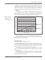
M1 MAX SPEED
M2 MAX SPEED
[default access: OEM]
[default access: OEM]
The maximum speed parameter defines the maximum controller output at full
throttle with the speed limit pot in its maximum speed position. For example, if
Mode 1 Maximum Speed is set at 60% and the speed limit pot is in its maximum
speed position, the controller will provide 60% output at full throttle in Mode 1.
NOTE: If a speed limit pot is not used, the maximum speed parameter is not
applicable unless Pin 4 is jumpered to Pin 1 (see page 22).
In the examples shown in Figure 17, the maximum speed parameter is set at
100% in Mode 2 and at 60% in Mode 1. The speed curves are straight lines in
these examples because we are assuming a 50% ramp shape setting. The throttle
response is not necessarily linear; see ramp shape parameter (page 38).
Fig. 17 Examples of
100
speed curves with the
speed limit pot in its
maximum speed position.
M2
MAXIMUM SPEED
(set at 100%)
90
PWM OUTPUT (percent)
80
70
M1 MAXIMUM SPEED
(set at 60%)
60
50
40
30
20
10
0
0
10
20
30
40
50
60
70
80
90
100
THROTTLE (percent)
The speed interlocks (see Section 4) ensure that Mode 2 is by definition the
faster of the two modes. The M1 Maximum Speed cannot be set higher than the
M2 Maximum Speed.
M1 MIN SPEED [default access: User]
M2 MIN SPEED [default access: User]
The minimum speed parameter defines the maximum controller output at full
throttle with the speed limit pot in its minimum speed position. For example, if
Mode 1 Minimum Speed is set at 20% and the speed limit pot is in its minimum
speed position, the controller will provide 20% output at full throttle. NOTE: If
Curtis PMC 1223/33, 1225/35, 1227/37 Manual
30
3 — PROGRAMMABLE PARAMETERS
a speed limit pot is not used, the minimum speed parameter defines the maximum
controller output at full throttle unless Pin 4 is jumpered to Pin 1 (see page 22).
If the Pin 4–1 jumper is used, the maximum speed parameter defines the
maximum controller output at full throttle and the minimum speed parameter is
not applicable.
In the examples shown in Figure 18, the minimum speed parameter is set at
50% in Mode 2 and at 20% in Mode 1. The speed curves are straight lines in
these examples because we are assuming a 50% ramp shape setting. The throttle
response is not necessarily linear; see ramp shape parameter (page 38).
Fig. 18 Examples of
100
speed curves with the
speed limit pot in its
minimum speed position.
90
PWM OUTPUT (percent)
80
70
60
M2 MINIMUM SPEED
(set at 50%)
50
40
30
M1 MINIMUM SPEED
(set at 20%)
20
10
0
0
10
20
30
40
50
60
70
80
90
100
THROTTLE (percent)
The speed interlocks (see Section 4) ensure that the minimum speed is set
lower than the maximum speed in each mode (M1 Min Speed < M1 Max Speed,
and M2 Min Speed < M2 Max Speed).
REVERSE SPEED
[default access: User]
The reverse speed parameter defines the maximum controller output in reverse
at full throttle with the speed limit pot in its maximum speed position. Reverse
speed is not affected by which mode (Mode 1, Mode 2) is selected. In the example
shown in Figure 19, the reverse speed parameter is set at 40%.
The “minimum” speed in reverse (the speed at full throttle with the speed
limit pot in its minimum speed position) is by definition equal to the M1
Minimum Speed.
The speed interlocks (see Section 4) ensure that the reverse speed parameter
cannot be adjusted below the M1 Minimum Speed or 25% (whichever is higher)
nor above the M1 Maximum Speed.
Curtis PMC 1223/33, 1225/35, 1227/37 Manual
31
3 — PROGRAMMABLE PARAMETERS
Fig. 19 Example of
100
reverse speed curve with
the speed limit pot in its
maximum speed position.
90
PWM OUTPUT (percent)
80
70
60
50
REVERSE SPEED
(set at 40%)
40
30
20
10
0
0
10
20
30
40
50
60
70
80
90
100
THROTTLE (percent)
CREEP SPEED [default access: OEM]
Creep speed helps to prevent vehicle rollback on inclines when the brake is
released but low throttle is applied. It is activated when the throttle is rotated out
of the throttle deadband (typically 8% of the full throttle range). The throttle
response is rescaled so that the controller’s output is adjustable over the full
throttle range, but starting at the programmed creep speed value. Creep speed is
programmable from 0% to 25% of the PWM duty cycle.
EMR REV SPEED
[default access: OEM]
(123X models only)
The emergency reverse speed parameter sets the speed at which the vehicle
moves away from the operator when the belly button input (Pin 10) is active. The
vehicle will move at this speed any time the belly button input is active, regardless
of throttle position. The emergency reverse speed is adjustable from 0% to 100%
of the PWM duty cycle. NOTE: If the controller is not factory-configured for the
emergency reverse option, this parameter will not be displayed in the Program
Menu.
Curtis PMC 1223/33, 1225/35, 1227/37 Manual
32
3 — PROGRAMMABLE PARAMETERS
Throttle Parameters
CAUTION
☞
It is strongly recommended that the throttle type and
direction parameters be adjusted only when the controller
is in a bench test setup. Changing these parameters while the
controller is installed in the vehicle could result in vehicle
runaway. If, for example, the throttle is a wigwag and the
throttle type parameter is changed from wigwag to singleended, the vehicle will register a throttle input and begin to
move without any operator control. If it is necessary to adjust
the throttle parameters with the controller in the vehicle, the
vehicle drive wheels should be jacked up until the mechanical
throttle, the programmed throttle type, and the programmed
direction type all match.
THROTTLE TYPE [default access: OEM]
The controller can be programmed to accept single-ended, wigwag, or inverted
wigwag signals from a 5kΩ, 3-wire pot or from a 0–5V voltage source. These
throttle styles are described in Table 2 (page 19).
The throttle input signal type options—Types “0” through “3” in the
Throttle Type programming menu—are listed in Table 4.
Table 4 PROGRAMMABLE THROTTLE INPUT SIGNAL TYPES
THROTTLE
TYPE
APPLICABILITY
5kΩ
0–5V
3-wire Pot Throttle
DESCRIPTION
0
✓
✓
wigwag
1
✓
✓
inverted wigwag
2
✓
3
Curtis PMC 1223/33, 1225/35, 1227/37 Manual
single-ended, with max. speed = 5kΩ
✓
single-ended, with max. speed = 5V
33
3 — PROGRAMMABLE PARAMETERS
DIRECTION
[default access: OEM]
The direction input type defines how the controller decides when to
change direction. For wigwag throttles, the direction input type defaults to
respond to the throttle input. For single-ended throttles, this parameter can be
set to either “single” or “dual.” The “single” setting allows the direction to be
chosen via a single switch, which pulls the direction/reverse input (Pin 13) high
when reverse is selected. It is not necessary for the switch to connect Pin 13 to Bwhen forward is selected. The “dual” setting requires input from two switches:
one for reverse (Pin 13) and one for forward (Pin 12). In the dual configuration
the switch must pull the forward or reverse input to B+ to select the direction.
Selecting both forward and reverse at the same time will cause the controller to
inhibit the output, disabling the vehicle until only one direction is selected.
These three options—Types “0” through “2” in the Direction programming
menu—are listed in Table 5.
Table 5 PROGRAMMABLE DIRECTION INPUT TYPES
APPLICABILITY
DIRECTION
INPUT
TYPE
Wigwag
Throttle
0
✓
Single-Ended
Throttle
DESCRIPTION
(responds to throttle input)
1
✓
“single” — allows direction to be
selected via a single switch
2
✓
“dual” — requires direction to be
selected via inputs from individual
forward and reverse switches
Curtis PMC 1223/33, 1225/35, 1227/37 Manual
34
3 — PROGRAMMABLE PARAMETERS
THRTL AUTOCAL [default access: OEM]
The throttle autocalibration parameter provides a means of easily and reliably
centering wigwag throttle pots. An audible tone and the Status LED assist the
assembler in accurately centering the pot in the throttle assembly. The controller
inhibits driving while in autocalibration mode, enabling the technician to adjust
the throttle potentiometer safely.
Throttle centering is accomplished as follows:
1. Jack the vehicle drive wheels off the ground or disconnect the
motor leads.
2. Completely assemble the throttle mechanism but do not tighten
the clamping mechanism that secures the potentiometer shaft to
the throttle lever.
3. Turn on the controller and plug in the 1307 handheld programmer.
4. Select the Program mode and scroll down to the throttle autocalibration parameter.
5. Turn the throttle autocalibration to On. At this point, the horn will
probably sound and the LED will go off, indicating that the throttle
pot is out of adjustment. If the horn does not sound and the LED
remains on, the pot is already centered and no further adjustment
is necessary.
6. With the throttle lever at the neutral position, adjust the potentiometer until the horn turns off and the LED goes on. The pot is
now adjusted to the proper value for neutral.
7. Tighten the clamping mechanism which secures the throttle lever
to the potentiometer shaft. Depress and release the throttle to verify
the mechanical return to neutral.
8. Turn the throttle autocalibration parameter to Off. The vehicle
will not drive if the throttle autocalibration parameter is left on.
Curtis PMC 1223/33, 1225/35, 1227/37 Manual
35
3 — PROGRAMMABLE PARAMETERS
THRTL DEADBAND [default access: OEM]
The throttle deadband parameter defines the throttle pot wiper voltage range
that the controller interprets as neutral. Increasing the throttle deadband setting
increases the neutral range. This parameter is especially useful with throttle
assemblies that do not reliably return to a well-defined neutral point, because it
allows the deadband to be defined wide enough to ensure that the controller goes
into neutral when the throttle mechanism is released.
Examples of deadband settings (20%, 15%, 8%) are shown in Figure 20,
along with the formulas used to determine the wiper voltage range (with respect
to B-) that the controller will interpret as neutral.
The programmer displays the throttle deadband parameter as a percentage
of the nominal throttle wiper voltage range and is adjustable from 5% to 30% in
0.5% increments. The default deadband setting is 8%.
The nominal throttle wiper voltage range is 4 volts (from 0.5 V to 4.5 V)
when measured relative to B-. This is true regardless of whether a single-ended or
wigwag throttle is used. When a single-ended throttle is used, the deadband
parameter sets a single threshold wiper voltage—that is, a wiper voltage (relative
to B-) at which the controller will begin to modulate. When a wigwag throttle
is used, the deadband parameter sets two threshold wiper voltages, one on either
side of the 2.5 V (2.5 kΩ) centerpoint, for forward and reverse.
NOTE: The throttle characteristics are defined in terms of wiper voltage
rather than throttle pot resistance because of the range of pot values that can be
used and the variation between pots of the same nominal value. The voltage
Single-Ended Throttle
Wigwag Throttle
0 0.5V
5V
0
2.5V
5V
20% Deadband
0.5V
4.5V
1.3V
2.1V
2.9V
4.5V
15% Deadband
4.5V
1.1V
0.5V
2.2V
0.5V
2.34V
2.8V
4.5V
8% Deadband
4.5V
0.8V
VDB = 0.5V + (DB%) (4V)
KEY:
Neutral
Deadband
0%
output
100%
output
2.66V
4.5V
VDB = 2.5V ± (0.5) (DB%) (4V)
Notes: Voltages shown are at the pot wiper relative to B-.
Voltages are relative to a nominal 5kΩ pot.
Fig. 20 Effect of adjusting the neutral deadband parameter.
Curtis PMC 1223/33, 1225/35, 1227/37 Manual
36
3 — PROGRAMMABLE PARAMETERS
values shown in Figure 20 will hold true for any potentiometer value within the
allowed 4.5 kΩ to 7.0 kΩ range.
THRTL GAIN
[default access: OEM]
The throttle gain parameter sets the wiper voltage required to produce 100%
controller output. Decreasing the throttle gain setting reduces the wiper voltage
and therefore the full stroke necessary to produce full controller output. This
feature allows reduced-range throttle assemblies to be accommodated.
Examples of throttle gain settings are shown in Figure 20, to illustrate the
effect of three different throttle gain settings (100%, 75%, 40%) on the fullstroke wiper voltage required to attain 100% controller output.
The programmer displays the throttle gain parameter as a percentage of the
active throttle voltage range. The active throttle voltage range is the nominal
voltage range (4V) minus the throttle deadband. As the throttle deadband is
increased, the active throttle voltage range decreases. The throttle gain parameter
can be adjusted from 10% to 100%, in 1% increments.
When a single-ended throttle is used, the throttle gain parameter sets the
maximum pot wiper voltage required to produce 100% output. When a wigwag
Single-Ended Throttle
Wigwag Throttle
0 0.5V
5V
0
2.5V
5V
100% Throttle Gain
15% Deadband
0.5V
4.5V
1.1V
2.2V
2.8V
2.2V
2.8V
2.34V
2.66V
2.34V
2.66V
4.5V
75% Throttle Gain
15% Deadband
0.93V
3.7V
1.1V
4.1V
75% Throttle Gain
8% Deadband
0.96V
3.6V
0.8V
4.0V
40% Throttle Gain
8% Deadband
0.8V
1.6V
2.3V
V100% = VDB + (Gain%) (4V) (1−DB%)
KEY:
Neutral
Deadband
0%
output
100%
output
3.4V
V100% = VDB ± (0.5) (Gain%) (4V) (1−DB%)
Notes: Voltages shown are at the pot wiper relative to B-.
Voltages are relative to a nominal 5kΩ pot.
Fig. 21 Effect of adjusting the throttle gain parameter.
Curtis PMC 1223/33, 1225/35, 1227/37 Manual
37
3 — PROGRAMMABLE PARAMETERS
throttle is used, the throttle gain parameter sets the pot wiper resistance required
to produce 100% output in both forward and reverse: the wiper voltage required
for full forward output is decreased, and the wiper voltage required for full reverse
output is increased.
NOTE: The throttle characteristics are defined in terms of wiper voltage
rather than throttle pot resistance because of the range of pot values that can be
used and the variation between pots of the same value. The voltage values shown
in Figure 21 will hold true for any potentiometer value within the allowed 4.5 kΩ
to 7.0 kΩ range.
[default access: OEM]
RAMP SHAPE
The ramp shape parameter determines the static throttle map of the controller.
This parameter modifies the vehicle’s response to the throttle input. Setting the
ramp shape parameter at 50% provides a linear output response to throttle
position. Values below 50% reduce the controller output at low throttle settings,
providing enhanced slow speed maneuverability. Values above 50% give the
vehicle a faster, jumpier feel at low throttle settings.
The ramp shape can be programmed in 1% increments between 20% and
70%. The ramp shape number refers to the PWM output at half throttle, as a
percentage of its full range. For example, if maximum speed is set at 100% and
creep speed is set at 0, a ramp shape of 50% will give 50% output at half throttle.
The 50% ramp shape corresponds to a linear response. Six ramp shapes (20, 30,
40, 50, 60, and 70%) are shown as examples in Figure 22, with the maximum
speed set at 100% and the creep speed set 0.
Fig. 22 Ramp shape
100
(throttle map) for controller with maximum speed
set at 100% and creep
speed set at 0.
RAMP SHAPE
MAXIMUM SPEED (100%)
90
70%
60%
80
50%
40%
PWM (percent)
70
30%
60
20%
50
40
30
CREEP
SPEED
(0)
20
10
0
0
10
20
30
40
50
60
70
80
90
100
THROTTLE (percent)
Curtis PMC 1223/33, 1225/35, 1227/37 Manual
38
3 — PROGRAMMABLE PARAMETERS
Changing either the maximum speed setting or the creep speed setting
changes the output range of the controller. Ramp shape output is always a
percentage of the output range (the range between the creep speed and maximum
speed settings).
Ramp shapes with the creep speed setting raised from zero to 10% are shown
in Figure 23.
Fig. 23 Ramp shape
100
(throttle map) for controller with maximum speed
set at 100% and creep
speed set at 10%.
RAMP SHAPE
MAXIMUM SPEED (100%)
90
70%
60%
80
50%
40%
PWM (percent)
70
30%
60
20%
50
40
30
20
10
CREEP SPEED (10%)
0
0
10
20
30
40
50
60
70
80
90
100
THROTTLE (percent)
In Figure 24, the creep speed is kept at 10% and the maximum speed setting
is dropped from 100% to 60%.
Fig. 24 Ramp shape
100
(throttle map) for controller with maximum speed
set at 60% and creep speed
set at 10%.
RAMP SHAPE
90
70%
60%
80
50%
MAXIMUM SPEED
(60%)
PWM (percent)
70
40%
30%
60
20%
50
CREEP SPEED
(10%)
40
30
20
10
0
0
10
20
30
40
50
60
70
80
90
100
THROTTLE (percent)
In all cases, the ramp shape number is the PWM output at half throttle, as a
percentage of its full range. In Figure 24, for example, the 50% ramp shape gives
Curtis PMC 1223/33, 1225/35, 1227/37 Manual
39
3 — PROGRAMMABLE PARAMETERS
35% PWM output at half throttle (halfway between 10% and 60%). The 30%
ramp shape gives 25% PWM at half throttle (30% of the range {which is 50%,
from 10% to 60%}, starting at 10% output, or {[.30 × 50%] + 10%} = 25%).
Current Limit Parameters
M1 MAIN C/L
M2 MAIN C/L
[default access: OEM]
[default access: OEM]
The main current limit parameter allows adjustment of the maximum current
the controller will supply to the motor during both drive and regen operation.
This parameter can be limited to protect the motor from excessive (potentially
damaging) currents or to reduce the maximum torque applied to the drive system
by the motor. It is adjustable from 50% to 100% of the rated maximum controller
current.
EMR REV C/L [default access: OEM]
(123X models only)
The emergency reverse current limit parameter defines the controller’s current
limit, regardless of the selected mode, when the belly button input (Pin 10) is
active. The emergency reverse current limit is adjustable from 0% to the full rated
controller current, regardless of the M1 and M2 main current limit settings. NOTE:
If the controller is not factory-configured for the emergency reverse option, this
parameter will not be displayed in the Program Menu.
CALIBRATION 5 [default access: OEM]
The regen current boost parameter allows the regenerative braking current limit
to be set higher than the main current limit. This feature can provide higher
braking torque to stop heavy vehicles on steep inclines. The regen current boost
parameter is adjustable from 0–25% above the programmed main current limit.
Curtis PMC 1223/33, 1225/35, 1227/37 Manual
40
3 — PROGRAMMABLE PARAMETERS
Output Driver Parameters
PROGRAM 1
[default access: OEM]
The program 1 parameter configures an auxiliary low side driver (Pin 7). This
output is rated at 1 amp and is short circuit protected. It can be programmed in
any of seven configurations (Types 0–6 in the Program 1 Driver programming
menu), as listed in Table 6.
Any component can be controlled by this output provided its current
requirements do not exceed the driver’s 1 amp rating.
Table 6 CONFIGURATION OPTIONS: PROGRAM 1 DRIVER
TYPE
TYPICAL USE
DESCRIPTION OF OPERATION
0
Electromagnetic Brake
Driver
Turns on when direction is selected* and
throttle is applied. Turns off, after the
specified brake delay, when PWM output
returns to zero or as commanded by the
anti-rollback and anti-roll-forward circuitry.
1
Brake Light Driver
Turns on when controller is in braking
mode. Turns off, after a half-second delay,
when braking stops.
2
Brush Motor Contactor
Coil Driver: Option 1
Turns on when direction is selected.* Turns
off, without a delay, when PWM output
returns to zero.
3
Brush Motor Contactor
Coil Driver: Option 2
Turns on when direction is selected.* Turns
off, after a 2 s delay, when PWM output
returns to zero.
4
Brush Motor Contactor
Coil Driver: Option 3
Turns on only when forward direction is
selected.* Turns off, with no delay, in any
other condition.
5
Brush Motor Contactor
Coil Driver: Option 4
Turns on only when forward direction is
selected.* Turns off, after a 2 s delay, in
any other condition.
6
Hour Meter
Turns on when power is turned on. Turns
off when power is turned off.
* A direction is selected as follows:
for wigwag throttles, when the throttle is rotated out of its neutral deadband;
for single-ended throttles, when a direction input has been selected.
Curtis PMC 1223/33, 1225/35, 1227/37 Manual
41
3 — PROGRAMMABLE PARAMETERS
PROGRAM 2
[default access: OEM]
(123X models only)
The program 2 parameter configures an auxiliary high side driver at Pin 16.
This output is rated at 2 amps and is not short circuit protected. It can be
programmed in any of eight configurations (Types 1–8 in the Program 2 Driver
programming menu), as listed in Table 7.
Any component can be controlled by this output provided its current
requirements do not exceed the driver’s 2 amp rating. However, since this driver
is not fault checked, it should not be used to drive an electromagnetic brake.
Table 7 CONFIGURATION OPTIONS: PROGRAM 2 DRIVER
TYPE
TYPICAL USE
DESCRIPTION OF OPERATION
0
N/A
N/A
1
Brake Light Driver
Turns on when controller is in braking
mode. Turns off, after a half-second delay,
when braking stops.
2
Brush Motor Contactor
Coil Driver: Option 1
Turns on when direction is selected.* Turns
off, without a delay, when PWM output
returns to zero.
3
Brush Motor Contactor
Coil Driver: Option 2
Turns on when direction is selected.* Turns
off, after a 2 s delay, when PWM output
returns to zero.
4
Brush Motor Contactor
Coil Driver: Option 3
Turns on only when forward direction is
selected.* Turns off, with no delay, in any
other condition.
5
Brush Motor Contactor
Coil Driver: Option 4
Turns on only when forward direction is
selected.* Turns off, after a 2 s delay, in
any other condition.
6
Hour Meter: Option 1
Turns on when power is turned on. Turns
off when power is turned off.
7
Hour Meter: Option 2
Turns on when electromagnetic brake is
released and a direction is selected.*
8
Belly Button Check
Periodically checks continuity of the wiring
from the belly button switch to the
controller’s emergency reverse input.
* A direction is selected as follows:
for wigwag throttles, when the throttle is rotated out of its neutral deadband;
for single-ended throttles, when a direction input has been selected.
Curtis PMC 1223/33, 1225/35, 1227/37 Manual
42
3 — PROGRAMMABLE PARAMETERS
PROGRAM 4
[default access: OEM]
The brake holding voltage parameter allows selection of a voltage less than the
full battery voltage to be applied to the brake coil when the brake is energized.
This parameter is applicable only when the Program 1 driver is configured as an
electromagnetic brake driver. The voltage is pulse width modulated and the
setting represents the percentage of nominal battery voltage applied to the coil.
Setting the parameter value to 100% allows the nominal battery voltage (e.g.,
24V) to be applied to the coil whenever the battery voltage exceeds its nominal
value. Setting the parameter value to 0% turns this feature off, causing the driver
to apply the actual DC battery voltage to the brake coil when the brake is
energized. When this parameter is set to a value greater than 0%, the nominal
battery voltage is applied for 1 second (to ensure the brake coil disengages the
brake) and then the programmed value is applied.
This feature provides greater vehicle range by reducing the power provided
to the brake coil during operation. It also reduces brake heating, and thus reduces
degradation of the brake’s pull-in characteristics at high temperatures.
Fault Parameters
HIGH PEDAL DIS [default access: OEM]
The high pedal disable (HPD) feature prevents the vehicle from moving if the
controller is turned on with the throttle applied. The HPD parameter allows
HPD to be enabled or disabled with the programmer. When programmed On,
HPD is active and controller output is inhibited if a throttle input greater than
the throttle deadband exists before power is applied to the controller. If HPD is
programmed Off, this protection feature is disabled and when the keyswitch (and
power enable switch, if used) is turned on the controller output will accelerate
normally to the commanded speed. NOTE: To meet TÜV requirements, the HPD
feature must be programmed On.
SRO
[default access: OEM]
(123X models only)
The static return to off (SRO) feature prevents the vehicle from being started
when “in gear.” If a direction is selected before the keyswitch and power enable
switch (is one is used) are turned on, the SRO feature will inhibit the controller’s
output.
SRO can be set relative to either direction (Type “1” in the SRO programming menu) or to forward only (Type “2”). With SRO set to Type 2, operation
is not inhibited if the reverse direction is selected prior to the keyswitch (and
power enable switch, if applicable) being turned on. SRO can also be disabled
(Type “0” is no SRO).
Curtis PMC 1223/33, 1225/35, 1227/37 Manual
43
3 — PROGRAMMABLE PARAMETERS
Other Parameters
M1 IR COEFF
M2 IR COEFF
[default access: OEM]
[default access: OEM]
IR compensation is a method by which the controller maintains a constant vehicle
speed despite changes in motor loading. The IR speed coefficient parameter
adjusts how aggressively the controller tries to maintain constant speed under
changing load conditions. This parameter should be set at or below the resistance
(in milliohms) of the traction drive motor system including motor wiring and
connections. The IR speed coefficient should never be set higher than this value,
because jerky and uncomfortable or unsafe operation could result. The IR speed
coefficient is adjustable down to 0, with 0 equaling no IR compensation.
CALIBRATION 4 [default access: OEM]
The IR stiffness parameter allows adjustment of the IR compensation characteristics at low speeds or light loads. The IR stiffness parameter can be programmed
from 0 to 32. Increasing the IR stiffness value makes the IR speed coefficient
response more aggressive at low speeds or light loads, but it also makes the throttle
response more harsh and abrupt. The IR stiffness value should therefore be set to
maximize the IR compensation response while maintaining as smooth a throttle
response as possible. For most applications, the midpoint setting (16) is a good
compromise.
Curtis PMC 1223/33, 1225/35, 1227/37 Manual
44
4 — OEM-SPECIFIED, FACTORY-SET PARAMETERS
4
OEM-SPECIFIED PARAMETERS
(SET AT FACTORY)
In addition to the programmable parameters described in Section 3, there are
various parameters that can be set at the factory per the OEM’s specification.
These parameters are not programmable with the 1307 programmer. If a change
is desired, the controller must be returned to the factory for reconfiguration.
Speed Parameters
SPEED INTERLOCKS
The speed interlocks prevent the speed parameters from being inadvertently
programmed to give abnormal operating characteristics.
The following relationships are ensured by the speed interlocks.
The minimum speeds can never be set higher than the corresponding
maximum speeds:
• M1 Min Speed cannot be set higher than M1 Max Speed
• M2 Min Speed cannot be set higher than M2 Max Speed
Mode 2 is by definition the faster of the two modes:
• M1 Max Speed cannot be set higher than M2 Max Speed
Reverse speed, which applies in both modes, must be within the Mode 1
speed range, and can never be lower than 25%:
• Reverse Speed must be set between M1 Min Speed
and M1 Max Speed
• Reverse Speed can never be set at less than 25%.
The speed interlocks can be disabled at the factory, if so desired. However,
this is not recommended unless a specific application requires that the existing
speed interlock relationships be violated.
Default setting ➤ Enabled
OEM specifies ➤ Enable: Yes or No
SPEED LIMIT POT FAULT
The speed limit pot fault function provides a check to determine whether the
speed limit pot wiper is correctly connected. If a wiper input is not detected, the
controller limits its maximum speed to the specified minimum speed (i.e., the
Curtis PMC 1223/33, 1225/35, 1227/37 Manual
45
4 — OEM-SPECIFIED, FACTORY-SET PARAMETERS
controller responds as if the speed limit pot is at its minimum speed position) until
the wiper wiring is repaired. No error code is given, either in the Diagnostics
Menu of the 1307 programmer or by the Status LED. However, this fault can be
verified by selecting the Test Menu and observing the speed limit pot value as the
pot position is changed. If the speed limit pot value does not change as the pot
is rotated through its range, a wiring problem may exist and the speed limit pot
wiring should be checked. If a speed limit pot will never be used in the application,
this fault check should be disabled at the factory.
Default setting ➤ Enabled
OEM specifies ➤ Enable: Yes or No
Fault Parameters
MAIN CONTACTOR FAULT CHECK
The main contactor fault function checks for proper operation of the main
contactor and the controller’s contractor coil driver. If a welded contactor,
missing or shorted contactor coil, or failed contactor coil driver is detected, the
controller will inhibit output to the motor and flash the Hardware Failsafe 3 error
code (3,3) via the Status LED. In applications for which these fault checks are
undesirable and not required, the main contactor fault function can be disabled
at the factory. However, it should be noted that this function is required to meet
TÜV regulations.
Default setting ➤ Enabled
OEM specifies ➤ Enable: Yes or No
OVERVOLTAGE
Overvoltage can occur if the battery pack disconnects or the power fuse opens
during regen braking. Controller operation resumes when the voltage is brought
under the overvoltage limit. Overvoltage protection is designed to protect the
controller from damage during brief periods of overvoltage. (NOTE: Attempts to
operate the controller for extended periods in an overvoltage condition—such as
trying to drive the vehicle with the charger attached and charging—will damage
it.) The controller can be configured to short the motor or to let it coast in the
event of overvoltage. The recommended setting is for overvoltage to short the
motor, and this configuration is required to meet TÜV regulations.
OEM specifies ➤ Short or Coast
Default setting ➤ Short
EMERGENCY REVERSE CHECK
(123X models only)
This parameter is applicable only when the Program 2 driver is configured for
emergency reverse. The emergency reverse check function defines how the
controller reacts to a fault in the emergency reverse wiring. If configured as
Curtis PMC 1223/33, 1225/35, 1227/37 Manual
46
4 — OEM-SPECIFIED, FACTORY-SET PARAMETERS
“Drive,” the controller will limit the vehicle’s maximum speed to the specified
emergency reverse speed regardless of mode or direction. This allows the vehicle
to be moved out of the way or driven back to the maintenance area for repair. If
configured as “disable,” the controller will inhibit all output to the motor until
the emergency reverse wiring fault has been corrected.
Default setting ➤ Drive
OEM specifies ➤ Drive or Disable
Other Parameters
SWITCH TYPE
The direction and mode selection switches can be specified as either momentary or
on/off. If a power enable switch will be used, it must be specified as a momentary
switch. Typically, the OEM specifies these three switches (direction, mode, power
enable) to be all momentary or all on/off, and not a combination of the two styles.
(NOTE: When on/off switches are specified, a power enable switch is not used and
the power enable pin is an output that drives the Status LED.) Consult Curtis
applications engineers if your application requires such a combination.
OEM specifies ➤ Momentary or On/Off
INPUT POLARITIES
With the exception of the keyswitch input (which must be active high), each of
the controller’s control signal inputs can be configured as active high or active low.
If an input is configured to be active high, the control function is recognized when
that input is pulled to battery B+. If an input is configured to be active low, the
control function is recognized when that input is pulled to battery B-. The
standard configuration is for all inputs to be active high with the exception of the
inhibit input, which is active low. Although each input can be configured either
active high or active low, there are some limitations on the allowable combinations.
OEM specifies ➤ Active: High or Low
Default setting ➤ Active High
(for each input)
(all except inhibit input)
EMERGENCY REVERSE
(123X models only)
This parameter defines whether the emergency reverse function is active. The
emergency reverse feature is typically used on vehicles with tiller handle control
and a belly button switch. This feature automatically transitions the vehicle to the
reverse direction—away from the operator—when the belly button switch is
engaged.
OEM specifies ➤ On or Off
Default setting ➤ Off
Curtis PMC 1223/33, 1225/35, 1227/37 Manual
47
4 — OEM-SPECIFIED, FACTORY-SET PARAMETERS
KEY OFF DECEL
The key off decel function decelerates the vehicle to zero speed per the specified
deceleration delay if the keyswitch is turned off while the vehicle is in motion. If
the key off decel function is disabled, the controller shorts the motor if the
keyswitch is turned off, causing a severely abrupt stop of the vehicle. It is therefore
recommended that the key off decel function be enabled.
Default setting ➤ On
OEM specifies ➤ On or Off
POWER SAVER
The power saver function releases the main contactor if the controller does not
receive any throttle commands in a 25-second period; it shuts the controller off
completely if no commands are received in a 25-minute period. This reduces the
residual current draw on the batteries and extends vehicle range. The keyswitch
must be cycled to activate the controller after the power saver has shut it down.
If the power saver function is disabled, the controller will remain on as long as the
keyswitch input is active.
OEM specifies ➤ Enable or Disable
Default setting ➤ Enable
MULTIMODE™
A key feature of Curtis PMC MultiMode™ controllers is their capability of being
configured for optimized performance in two distinctly defined modes. However,
should the OEM prefer to offer only a single mode of operation in a given
application, the MultiMode™ feature can be disabled. Additionally, each of the
seven MultiMode™ parameters can be individually defined as MultiMode™ or
single mode.
OEM specifies ➤ On or Off
Default setting ➤ On
Curtis PMC 1223/33, 1225/35, 1227/37 Manual
48
5 — INSTALLATION CHECKOUT
5
INSTALLATION CHECKOUT
Before operating the vehicle, carefully complete the following checkout procedure. If you find a problem during the checkout, refer to the diagnostics and
troubleshooting section (Section 7) for further information.
The installation checkout can be conducted with or without the handheld
programmer. The checkout procedure is easier with a programmer. Otherwise,
observe the LED for diagnostic codes. (The codes are listed in Section 7.)
☞
Put the vehicle up on blocks to get the drive wheels off
the ground before beginning these tests.
CAUTION
Do not stand, or allow anyone else to stand, directly in
front of or behind the vehicle during the checkout.
Make sure the keyswitch is off, the throttle is in neutral,
and the forward/reverse switches are open.
Wear safety glasses and use well-insulated tools.
1.
If a programmer is available, connect it to the programmer connector.
2.
Turn the keyswitch on. If your system includes a momentary power
enable switch, you must press this switch also. The programmer should
power up with an initial display, and the controller’s Status LED should
light up and remain steadily lit. If neither happens, check for continuity
in the keyswitch circuit and controller ground.
3.
If you are using a programmer, put it into the diagnostic mode by
pressing the DIAGNOSTICS key. The display should indicate “No Faults
Found.”
If there is a problem, the LED will flash a diagnostic code and the
programmer will display a diagnostic message. If you are conducting
the checkout without a programmer, look up the LED diagnostic code
in Section 7 (Diagnostics and Troubleshooting).
When the problem has been corrected, it may be necessary to cycle
the keyswitch in order to clear the fault code.
4.
Select a direction and operate the throttle. The motor should begin to
turn in the selected direction. If it does not, verify the wiring to the
Curtis PMC 1223/33, 1225/35, 1227/37 Manual
49
5 — INSTALLATION CHECKOUT
throttle and motor. The motor should run proportionally faster with
increasing throttle. If not, refer to Section 7.
5.
If you are using a programmer, put it into the test mode by pressing
the TEST key. Scroll down to observe the status of the switches: forward,
reverse, inhibit, push enable, mode select, and emergency reverse (if
applicable). Cycle each switch in turn, observing the programmer. The
programmer should display the correct status for each switch.
Similarly, check the program 1 and program 2 (if applicable) drivers
and the throttle and speed limit pot inputs. The programmer should
display the correct value for each driver and input.
6.
Verify that all options, such as high pedal disable (HPD) and static return
to off (SRO), are as desired.
7.
Take the vehicle down off the blocks and drive it in a clear area. It should
have smooth acceleration and good top speed.
8.
Test the deceleration and regen braking of the vehicle. Verify that the
deceleration and braking response is as desired.
9.
If it is enabled, check to see whether the emergency reverse (belly button)
feature is working correctly. If you have the optional emergency reverse
check wiring, verify that the circuit is operational by momentarily
disconnecting the emergency reverse wire leading to Pin 10. The vehicle
should either be disabled or be limited to the specified emergency reverse
speed and a fault indicated.
10.
If you used a programmer, disconnect it when you have completed the
checkout procedure.
BENCH TESTING WITH THE 1307 PROGRAMMER
With the simple bench test setup shown in Figure 25, the controller parameters
can be verified or adjusted without the controller being wired into a vehicle. The
wiring can be expanded to conduct a complete functional test on the bench.
Appropriately rated light bulbs, or a series of 12V bulbs, are an easily configured
test load with which to check the controller’s output power switching section and
auxiliary drivers (program 1, program 2).
The complete in-vehicle installation checkout, as described above, should
still be conducted before the vehicle is operated.
Curtis PMC 1223/33, 1225/35, 1227/37 Manual
50
5 — INSTALLATION CHECKOUT
Fig. 25 Bench test setup
for verifying and adjusting
the controller’s parameters.
+
+
CURTIS PMC
+
+
+
+
++++++++++++++++++++
POWER
SUPPLY
PROGRAM
SCROLL
DISPLAY
TEST
DIAGNOSTICS
CHANGE
VALUE
MORE INFO
KEYSWITCH
POWER
ENABLE
SWITCH
B+
CONTROLLER
BATTERY
CONNECTIONS
B-
Curtis PMC 1223/33, 1225/35, 1227/37 Manual
16
15
14
13
12
11
10
9
8
7
6
5
4
3
2
1
51
6 — PROGRAMMER OPERATION
6
PROGRAMMER OPERATION
The universal 1307 Curtis PMC handheld programmer (optional) allows you to
program, test, and diagnose Curtis PMC programmable controllers. The programmer is powered by the host controller, via a 4-pin connector located on the
controller.
When the programmer is first plugged into the controller, it displays the
controller’s model number, date of manufacture, and software revision code.
Following this initial display, the programmer displays a prompt for further
instructions.
+
+
CURTIS PMC
+
+
+
+
++++++++++++++++++++
A 4-line LCD display is
presented in this window
The LED in the corner of
the key lights up to identify
the mode of operation
PROGRAM
Scroll the 4-line
display (up and down)
with these two keys
TEST
SCROLL
DISPLAY
MORE INFO
A DIVISION OF CURTIS INSTRUMENTS INC.
Curtis PMC 1223/33, 1225/35, 1227/37 Manual
DIAGNOSTICS
CHANGE
VALUE
Choose the Program, Test,
or Diagnostics Mode with
one of these three keys
Change the selected
item’s value (up or down)
with these two keys
Get more information
about selected items with
this key. Also, use this
key in combination with
other keys to put the
programmer in Special
modes.
52
6 — PROGRAMMER OPERATION
The programmer is operated via an 8-key keypad. Three keys select operating
modes (Program, Test, Diagnostics), two scroll the display up and down, and two
change the values of selected parameters. The eighth key, the MORE INFO key, is
used to display further information about selected items within any of the three
standard modes. In addition, when pressed together with the PROGRAM or
the DIAGNOSTICS key, the MORE INFO key selects the Special Program mode or the
Special Diagnostics mode.
The display window presents a 4-line LCD display. The display is visible even in
bright sunlight. You can adjust the display contrast in the Special Program mode.
When one of the menu keys is pressed, the LED at the corner of the key lights up,
identifying the mode of programmer operation. For example, if the TEST key is
pressed, the LED at the corner of the key indicates that the programmer is now in
the Test mode, and the Test Menu is displayed.
Four lines of a menu are displayed at a time. The item at the top of the display
window is the selected item. To select an item, scroll within the menu until the
desired item is positioned at the top of the display window. The selected item is
always the top line. (In the Program mode, the selected item is highlighted by a
flashing arrow.) To modify a parameter or obtain more information about it, it
must be scrolled to the top position in the display window.
To scroll up and down within a menu, use the two SCROLL DISPLAY arrow keys.
The SCROLL DISPLAY arrow keys can be pressed repeatedly or be held down. When
a key is held down, the scrolling speed increases the longer the key is held.
SCROLL
DISPLAY
A small scroll bar at the left of the display window provides a rough indication of
the position of the four displayed items within the entire menu. That is, when the
bar is at the top of the window, the top of the menu is displayed. As you scroll
through the menu, the bar moves downward. When the bar is at the very bottom
of the window, you have reached the end of the menu. This sample display is from
the Program Menu:
scroll bar
Curtis PMC 1223/33, 1225/35, 1227/37 Manual
M1
M2
M1
M2
ACCE L RA T E
ACCE L RA T E
DECE L
DECE L
>1 .
2.
1.
1.
5
0
0
0
selected item
53
6 — PROGRAMMER OPERATION
CHANGE
VALUE
The two CHANGE VALUE arrow keys are used to increase or decrease the value of a
selected menu item. Like the SCROLL DISPLAY arrow keys, the CHANGE VALUE arrow
keys can be pressed repeatedly or be held down. The longer a key is held, the faster
the parameter changes. This allows rapid changing of any parameter.
An LED on each CHANGE VALUE arrow key indicates whether the key is
active and whether change is permissible. When the value of a parameter is being
increased, the LED on the “up” CHANGE VALUE key is on until you reach the
maximum value for that parameter. When the LED goes off, you cannot increase
the value.
The MORE INFO key has three functions: (1) to display more information about the
selected item, (2) to access the Special Program and Special Diagnostics modes
(when used together with the PROGRAM and DIAGNOSTICS keys), and (3) to initiate certain commands (such as the Self Test).
“More information” is available in all of the programmer operating modes.
After using the MORE INFO key to display additional information about the
selected item, press the MORE INFO key again to return to the original list.
OPERATING MODES:
PROGRAM, TEST, DIAGNOSTICS, SPECIAL PROGRAM, SPECIAL DIAGNOSTICS
PROGRAM
In the Program mode, accessed by pressing the PROGRAM key, all the adjustable
parameters and features of the controller are displayed (four at a time), along with
their present settings. The setting of the selected item—the item at the top of the
display, with the flashing arrow—can be changed, using the two CHANGE VALUE
keys.
The LEDs on these keys indicate whether there is still room for change. That
is, when the upper limit of a parameter’s range is reached, the LED on the “up”
key no longer lights up, indicating that the present value cannot be increased;
when the lower limit is reached, the LED on the “down” key no longer lights up.
The MORE INFO key, when used in the Program mode, displays a bar graph
along with the minimum and maximum values possible for the selected parameter. Parameters can be changed either from the main Program Menu or after
the MORE INFO key has been pressed and the additional information is being
displayed (see example below).
selected parameter
bar graph
minimum value
MODE 1 ACCE L ERA T I ON
RA T E , SECS
MI N 0 . 2
set value
1.3
MAX 3 . 0
maximum value
units
Curtis PMC 1223/33, 1225/35, 1227/37 Manual
54
6 — PROGRAMMER OPERATION
Some parameters on some controllers have dependencies on other parameters. This means that the available settings for one parameter may be dependent
on the limits of another parameter. For example, your controller may not allow
the reverse speed to be set below the Mode 1 minimum speed. In this example,
if you attempt to reduce the reverse speed below the M1 minimum speed, a
message will be displayed indicating that the minimum reverse speed is dependent on the M1 minimum speed.
The Program Menu is presented at the end of this section. NOTE: Some items
may not be available on all models.
TEST
DIAGNOSTICS
*
MORE INFO
PROGRAM
In the Test mode, accessed by pressing the TEST key, real-time information is
displayed about the status of the inputs, outputs, and controller temperature. For
example, when the status of the reverse input is displayed, it should read
“On/Off/On/Off/On/Off” as the switch is repeatedly turned on and off. In the
Test mode, the item of interest does not need to be the top item on the list; it only
needs to be among the four items visible in the window. The Test mode is useful
for checking out the operation of the controller during initial installation, and also
for troubleshooting should problems occur.
The MORE INFO key, when used in the Test mode, causes additional information to be displayed about the selected item (top line in the window).
The Test Menu is presented at the end of this section. NOTE: Some items
may not be available on all models.
In the Diagnostics mode, accessed by pressing the DIAGNOSTICS key, currently
active faults detected by the controller are displayed.
The MORE INFO key, when used in the Diagnostics mode, causes additional
information to be displayed about the selected item.
A list of the abbreviations used in the Diagnostics display is included at the
end of this section.
The Special Program mode allows you to perform a variety of tasks, most of
which are self-explanatory. Through the Special Program Menu, you can revert to
earlier settings, save controller settings into the programmer memory, load the
controller settings from the programmer into a controller, clear the controller’s
diagnostic history, adjust the contrast of the programmer’s LCD display, select the
language to be displayed by the programmer, and display basic information
(model number, etc.) about the controller and the programmer.
Curtis PMC 1223/33, 1225/35, 1227/37 Manual
55
6 — PROGRAMMER OPERATION
To access the Special Program mode, first press the MORE INFO key. Then,
while continuing to hold the MORE INFO key, press the PROGRAM key. The LED
on the PROGRAM key will light, just as when the programmer is in Program
mode. To distinguish between the Program and Special Program modes, look at
the menu items in the display.
CONTROLLER CLONING
Two of the Special Program Menu items—“Save Controller
Settings in Programmer” and “Load Programmer Settings
into Controller”—allow you to “clone” controllers. To do
this, simply program one controller to the desired settings,
save these settings in the programmer, and then load them
into other similar (same model number) controllers, thus
creating a family of controllers with identical settings.
The MORE INFO key is used initially to access the Special Program mode, and once
you are within the Special Program mode, it is used to perform the desired tasks.
To adjust the contrast in the display window, for example, select “Contrast
Adjustment” by scrolling until this item is at the top of the screen, and then
press MORE INFO to find out how to make the adjustment.
The Special Program Menu is presented at the end of this section.
*
MORE INFO DIAGNOSTICS
In the Special Diagnostics mode, the controller’s diagnostic history file is
displayed. This file includes a list of all faults observed and recorded by the
controller since the history was last cleared. (NOTE: The maximum and minimum
temperatures recorded by the controller are included in the Test Menu.) Each fault
is listed in the diagnostic history file only once, regardless of the number of times
it occurred.
To access Special Diagnostics, first press the MORE INFO key. Then, while
continuing to hold the MORE INFO key, press the DIAGNOSTICS key. The LED on
the DIAGNOSTICS key will light, just as when the programmer is in Diagnostics
mode.
The MORE INFO key, when used within the Special Diagnostics mode, causes
additional information to be displayed about the selected item.
To clear the diagnostic history file, put the programmer into the Special
Program mode, select “Clear Diagnostic History,” and press the MORE INFO key
for instructions. Clearing the diagnostic history file also resets the maximum/
minimum temperatures in the Test Menu.
Curtis PMC 1223/33, 1225/35, 1227/37 Manual
56
6 — PROGRAMMER OPERATION
PEACE-OF-MIND PROGRAMMING
Each time the programmer is connected to the controller, it acquires all the
controller’s parameters and stores them in its temporary memory. You can revert
back to these original settings at any time during a programming session via the
Special Program Menu. Select “Reset All Settings” by scrolling it to the top of the
display window, press the MORE INFO key, and follow the instructions displayed.
Any inadvertent changing of parameters can be “undone” using this procedure—
even if you can’t remember what the previous settings were—as long as the
programmer has not been unplugged and power has not been removed from
the controller.
Programmer Self Test
You can test the programmer by displaying two special test screens. Press
the MORE INFO key while the programmer is powering up. During the Self Test,
you can toggle between the two test screens by pressing the SCROLL DISPLAY keys.
The first screen turns on every LCD element, and the second screen displays all
the characters used in the various menus. As part of the Self Test, you can also test
the keys by pressing each one and observing whether its corner LED lights up. To
exit the Self Test, unplug the programmer or turn off the controller, and then repower it without holding the MORE INFO key.
⇐
SCROLL
DISPLAY
⇒
Curtis PMC 1223/33, 1225/35, 1227/37 Manual
! " # $%& ' ( ) * + , - . /
0 123 45 6 789 : ; <= >?
@A B C D E FG H I J K L M NO
P Q R S T U VWX Y Z x > Ω°
57
6 — PROGRAMMER OPERATION
PROGRAMMER MENUS
Items are listed for each menu in the order they appear in the actual menus
displayed by the 1307 programmer.
Program Menu (not all items available on all controllers)
D I R EC T I ON
Wigwag throttle centering utility, On or Off
Mode 1 acceleration rate, in seconds
Mode 2 acceleration rate, in seconds
Mode 1 forward deceleration rate, in seconds
Mode 2 forward deceleration rate, in seconds
Mode 1 reverse deceleration rate, in seconds
Mode 2 reverse deceleration rate, in seconds
Mode 1 maximum speed, as % PWM output
Mode 2 maximum speed, as % PWM output
Mode 1 minimum speed, as % PWM output
Mode 2 minimum speed, as % PWM output
Mode 1 main current limit
Mode 2 main current limit
Mode 1 IR compensation factor, in mΩ
Mode 2 IR compensation factor, in mΩ
Maximum reverse speed, as % PWM output
Throttle map
Creep speed, as % PWM output
Emergency reverse current limit
Emergency reverse speed, as % PWM output
Throttle type 1
Direction input type 2
T HR T L
Restricted range throttle adjustment, as % 5kΩ pot
T HR T L
AU T OC A L
M1
ACCE L
RA T E
M2
ACCE L
RA T E
M1
D ECE L
M2
D ECE L
M1
R E V
D ECE L
M2
R E V
D ECE L
M1
MA X
S P E ED
M2
MA X
S P E ED
M1
M I N
S P E ED
M2
M I N
S P E ED
M1
MA I N
C / L
M2
MA I N
C / L
M1
I R
COE F F
M2
I R
COE F F
RE V ERS E
RAMP
S P E ED
SH A P E
CRE E P
S P E ED
EMR
RE V
C / L
EMR
RE V
S P E ED
T HROT T L E
T HR T L
H I GH
T Y P E
GA I N
D E ADB AND
P ED A L
D I S
SRO
PROGRAM
1
PROGRAM
2
PROGRAM
4
CA L I BRA T I ON
5
CA L I BRA T I ON
4
Neutral deadband adjustment, as % of throttle gain
High pedal disable (HPD), On or Off
Static return to off (SRO) type 3
Program 1 driver type 4
Program 2 driver type 5
Brake coil holding voltage, as % nominal VBAT
Regen current limit boost, as % > main c/l
IR stiffness
(Notes are on the next page.)
Curtis PMC 1223/33, 1225/35, 1227/37 Manual
58
6 — PROGRAMMER OPERATION
Program Menu Notes
(For more detail on these options, see Section 3: Programmable Parameters.)
1
Throttle types
Type 0: wigwag (5kΩ pots or 5V throttles)
Type 1: inverted wigwag (5kΩ pots or 5V throttles)
Type 2: single-ended (0–5kΩ)
Type 3: single-ended (0–5V)
2
Direction input types
Type 0: wigwag throttle input
Type 1: single direction input
Type 2: dual direction input
3
SRO types
Type 0: no SRO
Type 1: SRO on KSI/power enable input plus direction input
Type 2: SRO on KSI/power enable input plus forward direction input
4
Program 1 driver types
Type 0: electromagnetic brake driver
Type 1: brake light driver
Type 2: brush contactor driver, off at neutral with no delay
Type 3: brush contactor driver, off at neutral with 2 second delay
Type 4: brush contactor driver, off at neutral and reverse with no delay
Type 5: brush contactor driver, off at neutral and reverse with 2 second delay
Type 6: hour meter driver, off when power enable is off
5
Program 2 driver types
Type 1: brake light driver
Type 2: brush contactor driver, off at neutral with no delay
Type 3: brush contactor driver, off at neutral with 2 second delay
Type 4: brush contactor driver, off at neutral and reverse with no delay
Type 5: brush contactor driver, off at neutral and reverse with 2 second delay
Type 6: hour meter driver, off when power enable is off
Type 7: hour meter driver, off when electromagnetic brake is engaged
Type 8: belly button wiring check
Curtis PMC 1223/33, 1225/35, 1227/37 Manual
59
6 — PROGRAMMER OPERATION
Test Menu (not all items available on all controllers)
T HROT T L E
S PD
B A T T
Throttle reading, in percent of full
Speed limit percent: 0–100%
Battery voltage across the capacitors
Motor voltage
Heatsink temperature
Mode input: on/off
Forward input: on/off
Reverse input: on/off
Inhibit input: on/off
Main contactor: on/off
Program 1 driver: on/off
Program 2 driver: on/off
Push enable input: on/off
Emergency reverse input: on/off
%
L I M I T
POT
VO L T AGE
MOTOR
VO L T AGE
° C
HE A T
S I N K
MOD E
I N PU T
A
F ORWA R D
I NPU T
RE V ERS E
I NPU T
I NH I B I T
MA I N
*
*
EM
CON T
DRVR
BRA K E
AUX
CON T
PUSH
EMR
A
EN A B L E
RE V
I N
I NPU T
* These text displays are fixed and will appear
regardless of how the program 1 and program 2
drivers are actually configured. See Section 3 for a
detailed description of the options available.
Special Program Menu
RE S E T
A L L
S E T T I NGS
CON T
S E T T I NGS >
PROG
PROG
S E T T I NGS >
CON T
C L E AR
D I AG
H I S TOR Y
CON T RA S T
AD J US TMEN T
L ANGUAGE
S E L EC T I ON
P ROGR A MME R
I N FO
CON T RO L L ER
I N FO
Curtis PMC 1223/33, 1225/35, 1227/37 Manual
Revert to original settings
Save controller settings in programmer
Load programmer settings in controller
Clear diagnostic history memory
Adjust display contrast
Select displayed language
Display programmer information
Display controller information
60
6 — PROGRAMMER OPERATION
Diagnostics and Special Diagnostics “Menu”
This is not a menu as such, but simply a list of the possible messages you may see
displayed when the programmer is operating in either of the Diagnostics modes.
The messages are listed in alphabetical order for easy reference.
B B
W I R I NG
EM
BRA K E
CH ECK
DR VR
F AU L T
H A RDWA R E
F A I L S A F E
1
H A RDWA R E
F A I L S A F E
2
H A RDWA R E
F A I L S A F E
3
H A RDWA R E
F A I L S A F E
4
HPD
HW
L OW
NO
F A I L S A F E
B A T T ERY
K N OWN
VO L T AGE
F AU L T S
OV ER VO L T AGE
PRECHARGE
F AU L T
PROC / W I R I NG
F AU L T
SRO
T HERMA L
CU T B ACK
T HROT T L E
a
b
F AU L T
1
BB wiring check failed
Electromagnetic brake driver fault
EEPROM fault
Output section fault
Main contactor fault
Overcurrent fault
High pedal disable (HPD) activated
Motor voltage fault
Battery voltage too low a
No known faults
Battery voltage too high b
Precharge fault
HPD fault present >5 seconds
Static return to off (SRO) activated
Cutback, due to over/under temp
Throttle fault
<16 volts (24V models); <21 volts (36V models); <27 volts (48V models)
>36 volts (24V models); >48 volts (36V models); >60 volts (48V models)
Curtis PMC 1223/33, 1225/35, 1227/37 Manual
61
7 — DIAGNOSTICS & TROUBLESHOOTING
7
DIAGNOSTICS AND TROUBLESHOOTING
The 1223/33, 1225/35, and 1227/37 controllers provide diagnostics information
to assist technicians in troubleshooting drive system problems. The diagnostics
information can be obtained in two ways: observing the fault codes issued by the
Status LED or reading the appropriate display on the handheld programmer.
PROGRAMMER DIAGNOSTICS
The programmer presents complete diagnostic information in plain language.
Faults are displayed in the Diagnostic Menu, and the status of the controller
inputs/outputs is displayed in the Test Menu.
Accessing the Diagnostic History Menu provides a list of the faults that have
occurred since the diagnostic history file was last cleared. Checking (and clearing)
the diagnostic history file is recommended each time the vehicle is brought in for
maintenance.
The following 4-step process is recommended for diagnosing and troubleshooting an inoperative vehicle: (1) visually inspect the vehicle for obvious
problems; (2) diagnose the problem, using the programmer; (3) test the circuitry
with the programmer; and (4) correct the problem. Repeat the last three steps as
necessary until the vehicle is operational.
Example: A vehicle that does not operate in “forward” is brought in
for repair.
1: Examine the vehicle and its wiring for any obvious problems,
such as broken wires or loose connections.
STEP
2: Connect the programmer, select the Diagnostics Menu, and
read the displayed fault information. In this example, the display
shows “No Known Faults,” indicating that the controller has not
detected anything out of the norm.
STEP
STEP 3:
Select the Test Menu, and observe the status of the inputs and
outputs in the forward direction. In this example, the display shows
that the forward switch did not close when “forward” was selected,
which means the problem is either in the forward switch or the switch
wiring.
STEP 4: Check or replace the forward switch and wiring and repeat the
test. If the programmer shows the forward switch closing and the
vehicle now drives normally, the problem has been corrected.
Refer to the troubleshooting chart (Table 8) for suggestions covering a wide range
of possible faults.
Curtis PMC 1223/33, 1225/35, 1227/37 Manual
62
7 — DIAGNOSTICS & TROUBLESHOOTING
Table 8 TROUBLESHOOTING CHART
LED
CODE
PROGRAMMER
LCD DISPLAY
EXPLANATION
POSSIBLE CAUSE
HARDWARE F A I L SA F E 2
output fault
1. Short in motor or in motor wiring.
2. Controller failure.
HARDWARE F A I L SA F E 4
overcurrent fault
1. Short in motor or in motor wiring.
2. Controller failure.
HARDWARE F A I L SA F E 1
EEPROM fault
1. EEPROM failure or fault.
HARDWARE F A I L SA F E 3
main contactor fault
1. Main contactor welded.
2. Main contactor driver fault.
3. Main contactor coil fault.
PRECHARG E F AU L T
precharge fault
1. Internal controller fault.
2. Low battery voltage.
HW F A I L SA F E
motor voltage fault
1. Motor voltage does not correspond to
throttle request.
2. M1 or M2 output shorted to B- or B+.
3. Internal motor short.
4. Controller failure.
2,1
SRO
SRO fault
1. Improper sequence of KSI, power enable,
and direction inputs.
2. Wrong SRO type selected.
3. Direction switch circuit open.
2,2
HPD
HPD fault
1. Improper sequence of KSI, power enable,
and throttle inputs.
2. Misadjusted throttle pot.
2,3
PROC / W I R I NG F AU L T
HPD fault present for >5 sec 1. Misadjusted throttle.
2. Broken throttle pot.
3. Broken throttle mechanism.
2,4
S PD L I M I T POT F AU L T
speed limit pot fault
1. Speed limit pot wiper wire broken.
2. Broken speed limit pot.
3,1
B B W I R I NG CHECK
emerg. reverse wiring fault
1. BB wire open.
2. BB check wire open.
3,2
EM BRAK E DRVR F AU L T
electromag. brake driver fault 1. Electromagnetic brake coil shorted or open.
2. Electromagnetic brake wiring open.
3,3
THROT T L E F AU L T 1
throttle fault
1.
2.
3.
4.
4,1
LOW B A T T ERY VOL T AGE
low battery voltage
1. Battery voltage <16 volts (24V models),
<21V (36V models), or <27V (48V models).
2. Corroded or loose battery terminal.
3. Loose controller terminal.
4,2
OVERVOL T AGE
overvoltage
1. Battery voltage >36 volts (24V models),
>48V (36V models), or >60V (48V models).
2. Vehicle operating with charger attached.
4,3
THERMA L CU T BACK
over-/under-temp. cutback
1.
2.
3.
4.
1,1
1,2
Curtis PMC 1223/33, 1225/35, 1227/37 Manual
Throttle input wire open.
Throttle input wire shorted to B- or B+.
Throttle pot defective.
Wrong throttle type selected.
Temperature >95°C or < -25°C.
Excessive load on vehicle.
Improper mounting of controller.
Operation in extreme environments.
63
7 — DIAGNOSTICS & TROUBLESHOOTING
LED DIAGNOSTICS
During normal operation, with no faults present, the Status LED is steadily on. If
the controller detects a fault, the Status LED provides two types of information.
First, it displays a slow flash (2 Hz) or a fast flash (4 Hz) to indicate the severity of
the fault. Slow-flash faults are self-clearing; as soon as the fault is corrected, the
vehicle will operate normally. Fast-flash faults (“❊” in Table 9) are considered to
be more serious in nature and require that the keyswitch (or power enable switch,
if one is used) be cycled to resume operation after the fault is corrected.
Then, after the severity indication has been active for 5 seconds, the Status
LED flashes a 2-digit fault identification code continuously until the fault is
corrected. For example, code “4,1”—low battery voltage—appears as:
¤ ¤ ¤ ¤
¤
(4,1)
¤ ¤ ¤ ¤ ¤
(4,1)
¤ ¤ ¤ ¤
¤
(4,1)
The codes are listed in Table 9.
Table 9 STATUS LED FAULT CODES
LED CODES
EXPLANATION
LED off
solid on
❊
❊
❊
no power or defective controller
controller operational; no faults
1,1
1,2
¤ ¤
¤ ¤¤
1,3
1,4
¤ ¤¤¤
¤ ¤¤¤¤
output fault or overcurrent fault
EEPROM, main contactor, precharge, or
motor voltage fault
[not used]
[not used]
2,1
2,2
2,3
2,4
¤¤
¤¤
¤¤
¤¤
static return to off (SRO) fault
high pedal disable (HPD) fault
HPD latching (HPD fault for >5 sec)
speed limit pot fault
3,1
3,2
3,3
3,4
¤¤¤
¤¤¤
¤¤¤
¤¤¤
4,1
4,2
4,3
4,4
¤¤¤¤
¤¤¤¤
¤¤¤¤
¤¤¤¤
¤
¤¤
¤¤¤
¤¤¤¤
¤
¤¤
¤¤¤
¤¤¤¤
¤
¤¤
¤¤¤
¤¤¤¤
emerg. rev. wiring fault (BB wiring check)
electromagnetic brake driver fault
throttle fault
[not used]
battery undervoltage
battery overvoltage
thermal cutback, due to over/under temp
[not used]
❊ = “Fast-flash” fault—must cycle keyswitch or power enable switch to clear.
NOTE:
Only one fault is indicated at a time, and faults are not queued up.
Curtis PMC 1223/33, 1225/35, 1227/37 Manual
64
7 — DIAGNOSTICS & TROUBLESHOOTING
Refer to the troubleshooting chart (Table 8) for suggestions about possible
causes of the various faults.
SPEED LIMIT POT FAULT
The controller will not display a fault if there is a problem with the speed limit pot
or its wiring. However, if the speed limit pot is broken or if any of its wires is open,
the vehicle drive speed will be limited to the specified minimum speed in the
selected mode. Open circuit faults can be verified by observing the speed limit pot
display in the Test Menu of the handheld programmer as this pot is adjusted. If
the speed limit pot display does not change as the pot is adjusted, there is a problem
with the pot wiring or the pot itself.
Curtis PMC 1223/33, 1225/35, 1227/37 Manual
65
8 — MAINTENANCE
8
MAINTENANCE
There are no user serviceable parts in the Curtis PMC 1223/33, 1225/35, and
1227/37 controllers. No attempt should be made to open, repair, or otherwise
modify the controller. Doing so may damage the controller and will void the
warranty. However, it is recommended that the controller be kept clean and dry
that its diagnostics history file be checked and cleared periodically.
CLEANING
1223/33 Controllers
The 1223/33 controllers do not have covers. Because there are exposed components on the circuit board, no cleaning is recommended. Instead, the controller
should be shielded from dirt and contaminants.
1225/35 and 1227/37 Controllers
The 1225/35 and 1227/37 controllers are covered units. It is recommended that
the controller exterior be cleaned periodically (see procedure below).
☞
CAUTION
When working around any battery powered vehicle, proper safety precautions should be taken. These include, but are not limited to: proper training,
wearing eye protection, and avoiding loose clothing and jewelry.
Use the following cleaning procedure for routine maintenance.
1.
Remove power by disconnecting the battery.
2.
Discharge the capacitors in the controller by connecting a load (such as
a contactor coil or a horn) across the controller’s B+ and B- terminals.
3.
Remove any dirt or corrosion from the connector area. The controller
should be wiped clean with a moist rag. Dry it before reconnecting the
battery.
4.
Make sure the connections are tight.
DIAGNOSTIC HISTORY
The handheld programmer can be used to access the controller’s diagnostic history
file. Connect the programmer, press the MORE INFO key, and then—while continuing to hold the MORE INFO key—press the DIAGNOSTICS key. The programmer will
read out all the faults that the controller has experienced since the last time the
Curtis PMC 1223/33, 1225/35, 1227/37 Manual
66
8 — MAINTENANCE
diagnostic history file was cleared. The faults may be intermittent faults, faults
caused by loose wires, or faults caused by operator errors. Faults such as contactor
faults may be the result of loose wires; contactor wiring should be carefully checked
out. Faults such as HPD or overtemperature may be caused by operator habits or
by overloading.
After a problem has been diagnosed and corrected, clearing the diagnostic
history file is advisable. This allows the controller to accumulate a new file of
faults. By checking the new diagnostic history file at a later date, you can readily
determine whether the problem was indeed completely fixed.
To clear the diagnostic history file, go to the Special Program Menu (by
pressing and holding the MORE INFO key, and then pressing the PROGRAM key),
scroll through the menu until “Clear Diagnostic History” is the top line in the
display, and then press MORE INFO again. The programmer will prompt you to
acknowledge or cancel. See Section 7 of this manual for more detail on programmer operation.
Curtis PMC 1223/33, 1225/35, 1227/37 Manual
67
APPENDIX A: GLOSSARY
APPENDIX A
GLOSSARY OF FEATURES AND FUNCTIONS
Acceleration rate
The acceleration rate is the time required for the controller to increase from 0 to
100% duty factor. The acceleration curve is controlled by the dynamic throttle
response, which is linear. The acceleration rate is programmable—see Section 3,
page 29.
Access rights
Each programmable parameter is assigned an access level—OEM or User—that
defines who is allowed to change that parameter. These levels are assigned by the
OEM when the controller is originally specified. Restricting parameter access to
the OEM reduces the likelihood of important performance characteristics being
changed by someone unfamiliar with the vehicle’s operation. In some cases, it may
be necessary to restrict a parameter’s access to ensure that it is not set to a value in
violation of TÜV regulations. The 1307-1101 User programmer can adjust only
those parameters with User access. The 1307-2101 OEM programmer can adjust
all the programmable parameters. Typically, OEMs supply 1307-1101 programmers to their dealers and distributors so that the User-access parameters (for
example, minimum speed and acceleration rate) can be set to each customer’s
liking in the store.
Anti-rollback
The anti-rollback feature prevents a vehicle that is traveling uphill in forward or
reverse from rolling back downhill when the throttle is released. It overrides the
brake delay and engages the electromagnetic brake as soon as the vehicle begins
to roll back down the incline.
Anti-roll-forward
The anti-roll-forward feature prevents a vehicle that is traveling downhill in
forward or reverse from rolling downhill excessively when the throttle is released.
It modifies the brake delay time proportional to the estimated speed at the time
the neutral throttle request is detected. This reduces “coasting” downhill when
the throttle is released during low speed operation.
Curtis PMC 1223/33, 1225/35, 1227/37 Manual
A-1
APPENDIX A: GLOSSARY
Auxiliary driver: “Program 1”
The program 1 driver is a short-circuit-protected low side driver capable of
driving a 1 ampere load to B-. The program 1 driver is programmable and can be
configured to drive an electromagnetic brake, hourmeter, brakelight, or sweeper/
scrubber brush motor contactor—see Section 3, page 41.
Auxiliary driver: “Program 2”
The program 2 driver is available only on 123X controllers (1233/1235/1237).
It is a high side driver capable of driving a 2 ampere load to B+, and is not short
circuit protected. The program 2 driver is programmable and be configured to
drive an hourmeter, brakelight, belly button check output, or sweeper/scrubber
brush motor contactor—see Section 3, page 42.
BB (= Belly Button; see Emergency reverse)
Brake delay time
The brake delay time specifies when the controller engages the electromagnetic
brake after the throttle is returned to neutral. This time delay, factory-specified
for a throttle change from 100% to 0% duty factor, is set to be long enough to
allow full deceleration without jerking the vehicle to a stop yet short enough so
that the brake is engaged immediately after the vehicle comes to a stop.
The anti-rollback and anti-roll-forward features override the brake delay to
prevent excessive travel on inclines when the throttle is released to neutral.
Brake holding voltage
This feature provides greater vehicle range and minimizes brake coil heating by
reducing the power provided to the electromagnetic brake coil during operation.
The brake holding voltage (“Program 4” in the Program Menu) is programmable—see Section 3, page 43.
Creep speed at first throttle
Creep speed, which is activated when the throttle is rotated out of the throttle
deadband, helps to prevent rollback when starting uphill on an incline with low
throttle. The creep speed parameter is programmable—see Section 3, page 32.
Curtis PMC 1223/33, 1225/35, 1227/37 Manual
A-2
APPENDIX A: GLOSSARY
Current limiting
Curtis PMC controllers limit the motor current to a preset maximum. This feature
protects the controller from damage that might result if the current were limited
only by motor demand. PWM output to the power section is reduced until the
motor current falls below the set limit level.
In addition to protecting the controller, the current limit feature also
protects the rest of the system. By eliminating high current surges during vehicle
acceleration, stress on the motor and batteries is reduced and their efficiency
enhanced. Similarly, there is less wear and tear on the vehicle drivetrain, as well
as on the ground on which the vehicle rides (an important consideration with
golf courses and tennis courts, for example).
The current limit is programmable—see Section 3, page 40.
Current multiplication
During acceleration and during reduced speed operation, the Curtis PMC
controller allows more current to flow into the motor than flows out of the
battery. The controller acts like a dc transformer, taking in low current and high
voltage (the full battery voltage) and putting out high current and low voltage.
The battery needs to supply only a fraction of the current that would be required
if a resistive controller were used. The current multiplication feature gives vehicles
using Curtis PMC controllers dramatically greater driving range per battery
charge.
Deceleration rate
The deceleration rate is the time required for the controller to decrease from 100%
duty factor to zero. The deceleration rate and reverse deceleration rate can be
defined separately. The deceleration rate controls how quickly the vehicle slows to
a stop when it is moving forward. The reverse deceleration rate controls how
quickly the vehicle slows to a stop when it is moving in reverse. The two
deceleration rates are independent because it may be desirable to define a faster
deceleration rate in the reverse direction.
The deceleration curve is controlled by the dynamic throttle response,
which is linear. The deceleration rates are programmable—see Section 3, page 29.
Emergency reverse
The emergency reverse feature is available only on 123X controllers (1233/1235/
1237). Emergency reverse is activated when the keyswitch is On and the
emergency reverse switch (the BB, or “belly button” switch) is pressed. After the
BB switch is released, normal controller operation is not resumed until zero
Curtis PMC 1223/33, 1225/35, 1227/37 Manual
A-3
APPENDIX A: GLOSSARY
throttle is selected. However, repeatedly pressing the BB switch will reactivate the
emergency reverse function each time. The emergency reverse speed and current
limit are both programmable—see Section 3, page 32 (speed) and page 40 (current
limit).
ET-series electronic throttles
The ET-XXX is a wigwag-style throttle control assembly, manufactured by
Hardellet for Curtis. It provides a 0–5V signal in both the forward and reverse
directions. Use of this throttle control assembly requires that the controller throttle
input be configured as single-ended, with a separate direction switch.
Fault detection and response
An internal microcontroller automatically maintains surveillance over the functioning of the controller. When a fault is detected, the appropriate fault code is
signalled via the Status LED and is also displayed on the handheld programmer
via the Diagnostics Menu. See Section 7, Diagnostics and Troubleshooting.
The controller responds to overvoltage, undervoltage, thermal cutback, and
emergency reverse wiring faults by reducing output. All other faults cause a
complete shutdown of the motor drive.
The automatic fault detection system includes:
— current limit fault
— EEPROM fault
— emergency reverse wiring fault
— electromagnetic brake driver fault
— high pedal disable (HPD) fault
— main contactor fault
— memory checks upon start-up
— motor voltage fault
— output section fault
— overtemperature
— overvoltage
— precharge fault
— procedural/wiring fault (HPD fault >5 sec)
— static return to off (SRO) fault
— throttle fault
— undertemperature
— undervoltage
— watchdog (external)
— watchdog (internal).
Curtis PMC 1223/33, 1225/35, 1227/37 Manual
A-4
APPENDIX A: GLOSSARY
Fault recording
Fault events are recorded in the controller’s memory. Multiple occurrences of the
same fault are recorded as one occurrence.
The fault event list can be loaded into the programmer for readout. The
Special Diagnostics mode provides access to the controller’s diagnostic history
file—the entire fault event list created since the diagnostic history file was last
cleared. The Diagnostics mode, on the other hand, provides information about
only the currently active faults.
Fault recovery (including recovery from disable)
Almost all faults require a cycling of the keyswitch (or power enable switch, if used)
to reset the controller and enable operation. The only exceptions are these:
FAULT
RECOVERY
BB wiring
HPD
overvoltage
SRO
thermal cutback
throttle fault
undervoltage
(all other faults)
clears when fault is corrected
lower throttle to below HPD threshold
when battery voltage drops below overvoltage
when proper sequence is followed
when temperature changes
clears when condition is gone
when battery voltage rises above undervoltage
(cycle keyswitch or power enable switch)
Full bridge
The 1223/33, 1225/35, 1227/37 controllers use a full bridge design for power
switching and direction selection. This eliminates the need for external or onboard forward/reverse contactors. The result is a higher reliability product that is
simpler to install.
High-pedal-disable (HPD)
The HPD feature prevents controller output if the controller is turned on when
the throttle is not in neutral. If the operator attempts to start the vehicle when the
throttle is already applied, the controller output will remain off. For the vehicle to
start, the controller must receive an input to KSI before receiving a throttle input.
In addition to providing routine smooth starts, HPD also protects against
accidental sudden starts if problems in the throttle linkage (e.g., bent parts, broken
return spring) give a throttle input signal to the controller even with the throttle
released. The HPD feature can be programmed On or Off—see Section 3, page 43.
HPD must be set to On to meet TÜV regulations.
Curtis PMC 1223/33, 1225/35, 1227/37 Manual
A-5
APPENDIX A: GLOSSARY
HPD lockout (procedural/wiring fault)
After 5 seconds of a continuous HPD fault, driving is inhibited until power to the
controller is cycled. This feature prevents operation of a vehicle with a defective
or misadjusted throttle.
Inhibit
The inhibit input is used to put the vehicle in a safe, non-drivable state during
battery charging or under other conditions where this precaution is desired—see
Section 2, page 25.
IR compensation
IR compensation is a technique used to provide near-constant speed control of the
vehicle during varying motor loads despite resistive motor losses (IR). Internal
circuitry monitors the current and voltage in the motor relative to throttle position
and adjusts the controller output to maintain as constant a speed as possible during
varying motor loads. The motor load varies as a function of inclines/declines in
terrain or when the vehicle encounters an obstacle, such as debris on the sidewalk.
The programmable IR speed coefficient parameter adjusts how aggressively the
controller tries to maintain constant speed under changing load conditions—see
Section 3, page 44.
ISO pot fault
All 1223/33, 1225/35, and 1227/37 controllers contain throttle pot fault circuitry
that meets ISO 7176 requirements.
Key off deceleration
The key off deceleration feature provides controlled deceleration—rather than an
abrupt stop—when the keyswitch is turned off for any reason while driving.
KSI
KSI (Key Switch Input) provides power to the controller’s logic board, initializes
the microprocessor, and starts diagnostics. If both a keyswitch and a power enable
switch are used, the keyswitch will provide power to the controller’s logic but the
power enable switch must also be activated in order to drive the vehicle. The
keyswitch functions as a master switch for the vehicle, to turn the system off when
not in use.
Curtis PMC 1223/33, 1225/35, 1227/37 Manual
A-6
APPENDIX A: GLOSSARY
LEDs
The 1223/33, 1225/35, and 1227/37 controllers allow for the use of Light
Emitting Diodes (LEDs) to show the condition of certain switches and to provide
system fault information—see Section 2, page 25.
Load compensation (see IR compensation)
Missing brake detection
If the electromagnetic brake coil circuit is open, the controller inhibits driving and
shorts the motor. If a mechanical brake release lever is used, it is recommended that
a switch operated by this lever be wired in series with the brake coil to inhibit
driving when the brake is mechanically released, as shown in the wiring diagrams.
This provides a safety feature by ensuring the vehicle cannot be driven when the
brake cannot be engaged. A brake coil disable switch or a self-resetting brake is
required by TÜV regulations.
Momentary switch input
A control input configured for a momentary switch changes its state each time it
receives a B+ signal. If the B+ signal is removed, the control function remains
latched. For example, if the Mode input is configured for a momentary switch and
the controller is in Mode 1, activating the switch momentarily (applying B+) puts
the controller into Mode 2. The controller will remain in Mode 2 until another
B+ signal is received. When the switch is again momentarily activated (B+ again
applied to the Mode input) the controller will transition back to Mode 1
operation. Membrane switches built into a control pad are usually used with
momentary control inputs.
MOSFET
A MOSFET (metal oxide semiconductor field effect transistor) is a type of
transistor characterized by its fast switching speeds and very low losses.
Motor voltage fault
The motor voltage fault check circuit verifies that the average voltage being applied
to the motor corresponds to that commanded by the throttle input. If there is a
discrepancy between the throttle request and voltage across the motor, the
controller is shut down. The motor voltage fault check is mandated by TÜV
requirements.
Curtis PMC 1223/33, 1225/35, 1227/37 Manual
A-7
APPENDIX A: GLOSSARY
MultiMode™
The MultiMode™ feature of these controllers allows the vehicle to be operated
with two distinct sets of characteristics. The two modes can be programmed to be
suitable for operation under different conditions, such as slow precise indoor
maneuvering in Mode 1 and faster, long distance, outdoor travel in Mode 2. The
following parameters can be set independently in the two modes:
— main current limit
— maximum speed
— minimum speed
— acceleration rate
— deceleration rate
— reverse deceleration rate
— IR speed compensation.
OEM (= Original Equipment Manufacturer)
On/Off switch input
A control input configured for an on/off switch is in a specific state depending on
its applied voltage. For example, if the mode input is configured for an on/off
switch, turning the switch on (applying B+) puts the controller into Mode 2. The
controller will remain in Mode 2 as long as the switch is On and is therefore
applying B+ to the mode input. When the mode switch is turned off (and B- is
applied to the mode input) the controller will transition to Mode 1 operation.
SPST toggle switches are usually used with on/off control inputs.
Overtemperature (see Thermal protection)
Overvoltage protection
The overvoltage protection feature shuts down the regenerative current path to the
controller if the voltage exceeds the factory-set limit. Controller operation resumes
when the voltage is brought within the acceptable range. The cutoff voltage and
re-enable voltage are percentages of the battery voltage, and are set at the factory.
The controller can be configured to short the motor (required to meet TÜV
regulations) or to let it coast in the event of overvoltage—see Section 4, page 46.
Power saver
The power saver feature minimizes battery power drain if the vehicle is left on but
is not being used. The main contactor is released after 25 seconds if no throttle
Curtis PMC 1223/33, 1225/35, 1227/37 Manual
A-8
APPENDIX A: GLOSSARY
commands are received. Normal operation resumes when the throttle is moved.
If the throttle remains at neutral for 25 minutes, the controller powers down
completely; normal operation resumes when the keyswitch (or power enable
switch, if used) is cycled.
Precharge
The precharge feature soft-charges the controller’s internal capacitor bank when
the controller is first turned on and before the main relay is engaged. This protects
the main relay’s contacts from the large inrush currents that exist when battery
voltage is applied to a discharged capacitor bank.
Precharge fault
The precharge fault feature keeps the main contactor from being engaged if the
internal capacitor bank voltage does not rise above the minimum threshold within
500 ms after the controller is turned on. This protects the system against faults that
short the controller’s internal B+ bus.
Procedural/wiring fault (HPD lockout)
After 5 seconds of a continuous HPD fault, driving is inhibited until power to the
controller is cycled. This feature prevents operation of a vehicle with a defective
or misadjusted throttle.
Push
The push feature allows the brake to be released electrically so that the vehicle can
be pushed. This is convenient when, for example, it is appropriate for an
attendant to manually push a mobility aid scooter. The push feature inhibits the
controller’s drive function until the push switch is turned off, thus ensuring that
the vehicle cannot be operated in a condition in which the electromagnetic brake
cannot be engaged. To use the push feature, the batteries must be wired to the
controller, the keyswitch must be enabled, the vehicle must be stopped, and the
electromagnetic brake must be engaged.
If the vehicle is pushed too fast, indicating a runaway or other abnormal
condition, the controller will automatically turn on and limit the speed of the
vehicle (see Push-too-fast, below).
Push-too-fast
The push-too-fast feature limits the maximum speed at which the vehicle can be
pushed, thus guarding against unpowered vehicle runaway with the electromagCurtis PMC 1223/33, 1225/35, 1227/37 Manual
A-9
APPENDIX A: GLOSSARY
netic brake mechanically released. The controller, even if it is powered off and
there are no batteries in the system, will detect the motor voltage created by the
moving vehicle. When this voltage becomes high enough, indicating that significant vehicle speed has been reached, the controller logic will power up and turn
on the MOSFET power sections to short the motor and limit the speed of the
vehicle.
PWM
Pulse width modulation (PWM), also called “chopping,” is a technique that
switches battery voltage to the motor on and off very quickly, thereby controlling
the speed of the motor. Curtis PMC 1200 series controllers use high frequency
PWM—15 kHz—which permits silent, efficient operation.
Ramp shape (static throttle map)
The ramp shape parameter determines the controller’s static throttle map.
Adjusting the throttle characteristics to suit your specific application can enhance
your vehicle’s performance. The ramp shape parameter is programmable—see
Section 3, page 38.
Regenerative braking
The 1223/33, 1225/35, 1227/37 controllers use regenerative braking to slow the
vehicle to a stop and to reduce speed when traveling downhill. Regenerative
braking means that the energy used to slow the vehicle is channeled back into the
batteries, resulting in longer vehicle range between charges.
Regen current boost
By allowing the regenerative braking current to be set up to 25% higher than the
main drive current limit, this feature can provide the higher braking torque
necessary to stop very heavy vehicles on steep inclines. The regen current boost
parameter (“Calibration 5” in the Program Menu) is programmable—see Section
3, page 40.
Reverse polarity protection
If the B+ and B- connections are reversed to an otherwise properly wired
controller, it will not allow the main contactor to be engaged. This protects the
power MOSFET output section from being damaged by the reverse polarity.
Curtis PMC 1223/33, 1225/35, 1227/37 Manual
A-10
APPENDIX A: GLOSSARY
Smooth, stepless operation
Like all Curtis PMC 1200 Series controllers, 1223/33, 1225/35, 1227/37 models
allow superior operator control of the vehicle’s drive motor speed. The amount
of current delivered to the motor is set by varying the “on” time (duty cycle) of
the controller’s power MOSFET transistors. This technique—pulse width modulation (PWM)—permits silent, stepless operation.
Speed interlocks
The 1223/33, 1225/35, and 1227/37 controllers come standard with speed
interlocks. The speed interlocks prevent the speed parameters from being inadvertently programmed to give abnormal operating characteristics. The speed
interlocks can be disabled at the factory, if so desired—see Section 4, page 45.
However, this is not recommended unless a specific application requires that the
existing speed interlock relationships be violated.
Speed settings
There are two upper-limit speed settings in each mode: “maximum” and “minimum.” The “maximum speed” setting defines the highest controller output at full
throttle with the speed limit pot in its maximum speed position. The “minimum
speed” setting defines the highest controller output at full throttle with the speed
limit pot in its minimum speed position. The “maximum” and “minimum”
speeds are programmable independently for Mode 1 and Mode 2—see Section 3,
page 30.
Static-return-to-off (SRO)
The SRO feature prevents the vehicle from being started when “in gear.” SRO
checks the sequencing of KSI (and power enable input, if a power enable switch
is used) relative to either direction (Type 1) or relative to forward only (Type 2).
The controller can be programmed to provide Type 0 (no SRO), Type 1 SRO, or
Type 2 SRO—see Section 3, page 43.
Temperature compensation
The 1223/33, 1225/35, 1227/37 controllers are specified to operate at their
temperature-compensated current limits for one full minute. They employ
temperature compensation to maintain consistent current limit and IR compensation levels. This minimizes performance variation resulting from changes in
controller or ambient temperatures. There is, however, a small rolloff in the
Curtis PMC 1223/33, 1225/35, 1227/37 Manual
A-11
APPENDIX A: GLOSSARY
current limit value as the controller’s power section heats up. Variations of up to
10% of the specified 1-minute current limit rating may be observed in applications where the controller undergoes significant heating. Attention to controller
heatsinking will minimize this effect.
Temperature data
The temperature displayed in the 1307 programmer’s Test Menu is the instantaneous heatsink temperature at that moment, in degrees Celsius.
Thermal protection
Because of their efficiency and thermal design, Curtis PMC controllers should
barely get warm in normal operation. Overheating can occur, however, if the
controller is undersized for its application or otherwise overloaded. If the internal
temperature of the controller exceeds 90°C (194°F), the main current limit
decreases steadily until it is reduced to zero at 105°C (221°F). At the reduced
performance level, the vehicle can be maneuvered out of the way and parked.
NOTE: To prevent loss of braking effort, regenerative current limit is not cut back
in overtemperature conditions.
Full current limit and performance return automatically after the controller
cools down. Although this action is usually not damaging to the controller*, it
does suggest a mismatch. If thermal cutback occurs often in normal vehicle
operation, the controller is probably undersized for the application and a higher
current model should be used.
The controller is similarly protected from undertemperature. Should its
internal temperature fall below -25°C (-13°F), the current limit decreases to
approximately one-half of the set current. When the controller warms up, full
current limit and performance return automatically.
Throttle deadband (neutral deadband)
The throttle deadband is the pot wiper voltage range that the controller interprets
as neutral. The throttle deadband is typically set at 8%. A higher setting increases
the neutral range, which can be useful with throttle assemblies that do not return
reliably to a well-defined neutral point. The throttle deadband parameter is
programmable—see Section 3, page 36.
* Because
braking current does not roll off in overtemperature,
motor braking down a steep slope with a heavy load for an
extended period could cause overheating of the MOSFETs.
Curtis PMC 1223/33, 1225/35, 1227/37 Manual
A-12
APPENDIX A: GLOSSARY
Throttle fault protection
5kΩ, 3-wire potentiometer throttle
For 5kΩ, 3-wire potentiometer throttles, the throttle fault detection circuitry
meets ISO 7176 requirements. Also, throttle pot resistances outside the range of
4.5–7.5 kΩ are considered to be indicative of a faulty pot or faulty wiring, in
which case the controller will register a pot fault. Fault detection causes the
controller to decelerate to zero output. The controller returns to normal operation
when the fault has been repaired.
0–5V throttle
Because the throttle input voltage is referenced to B- and no connection is made
to the pot high and pot low inputs, complete throttle pot protection is lost with
0–5V throttles. Only a broken wire fault to the pot wiper input will be detected
by the controller. Therefore, it is the responsibility of the vehicle manufacturer
to provide throttle fault detection for 0–5V throttles.
Throttle gain (see Throttle: restricted range)
Throttle map
The static throttle map (duty factor as a function of throttle position) is adjustable,
in order to provide the proper feel for the many types of vehicles that use the 1223/
33, 1225/35, and 1227/37 controllers. The throttle map parameter is called “ramp
shape,” and is programmable—see Section 3, page 38.
Throttle response
The dynamic throttle response (duty factor as a function of time) is shaped by the
acceleration and deceleration rate settings. Dynamic throttle response is linear.
The newest throttle input is mapped to the throttle map, and the controller then
automatically accelerates (or decelerates) through a straight line until the new
throttle demand is obtained.
Throttle: restricted range
The 1223/33, 1225/35, and 1227/37 controllers can be programmed for use with
restricted range throttle inputs via the throttle gain parameter—see Section 3, page
37. This capability allows throttle pots with less than 5kΩ total full stroke wiper
resistance to be used.
Curtis PMC 1223/33, 1225/35, 1227/37 Manual
A-13
APPENDIX A: GLOSSARY
Throttle types
The controller can be programmed to accept wigwag or single-ended signals from
a 5kΩ, 3-wire pot or from a 0–5V voltage source—see Section 3, page 33.
Undertemperature (see Thermal protection)
Undervoltage protection
Undervoltage protection automatically cuts back the controller output if battery
voltage is detected below the undervoltage point at start-up, or when the battery
voltage is pulled below the undervoltage point by an external load. The undervoltage
cutback point is not adjustable.
During normal operation, the controller duty factor will be reduced when
the batteries discharge down to less than the undervoltage level. If the motor
current is such that the batteries are being pulled below the minimum point, the
duty factor will be reduced until the battery voltage recovers to the minimum
level. In this way the controller “servos” the duty factor around the point which
maintains the minimum allowed battery voltage.
If the voltage continues to drop below the undervoltage level to a severe
undervoltage condition (due to battery drain or external load), the controller
continues to behave in a predictable fashion, with its output disabled.
Watchdog (external, internal)
The external watchdog timer guards against a complete failure of the microprocessor, which would incapacitate the internal watchdog timer. This independent
system check on the microprocessor meets the EEC’s requirement for backup fault
detection.
The external watchdog timer safety circuit shuts down the controller (and
the microprocessor) if the software fails to generate a periodic external pulse train.
This pulse train can only be created if the microprocessor is operating. If not
periodically reset, the watchdog timer times out after 15–20 msec and turns off
the controller. The external watchdog also directly shuts down the PWM drive
to the MOSFETs. It can only be reset by cycling KSI (or the power enable switch,
if one is used).
The internal watchdog timer must be reset periodically by correct sequential
execution of the software. If not reset, the internal timer times out and the
microprocessor is “warm booted.” This causes the microprocessor to shut down
its outputs—thus shutting down the controller—and attempt to restart.
Curtis PMC 1223/33, 1225/35, 1227/37 Manual
A-14
APPENDIX
APPENDIXA:
B: GLOSSARY
THROTTLES
APPENDIX B
THROTTLE MOUNTING DIMENSIONS
Fig. B-1 Mounting
dimensions,
Curtis PMC standard
5kΩ, 3-wire throttle
potentiometer,
p/n 98191.
14
(0.56)
20 (0.81)
28 (1.1)
6 (0.25)
35 (1.38)
ELEC. SPECS: ELECTRICAL TRAVEL 40°± 3°
TOTAL RESISTANCE (nominal) 5 kΩ
HOPOFF RESISTANCE (max) 10 Ω
Dimensions in millimeters and (inches)
Fig. B-2 Mounting
dimensions,
Curtis PMC potboxes
PB-5, -6, -9, and -10.
35
(1.38)
45°
42 (1.65)
10 (0.38)
60
(2.37)
32
(1.25)
52 (2.06)
RIGHT-HAND OPERATION
COM. N.O. N.C.
WITH MICROSWITCH: PB-6
WITHOUT MICROSWITCH: PB-5
6
(0.25)
89 (3.5)
102 (4.0)
LEFT-HAND OPERATION
N.C. N.O. COM.
WITH MICROSWITCH: PB-9
WITHOUT MICROSWITCH: PB-10
Dimensions in millimeters and (inches)
Curtis PMC 1223/33, 1225/35, 1227/37 Manual
A-15
B-1
APPENDIX B: THROTTLES
APPENDIX A: GLOSSARY
Fig. B-3 Curtis PMC footpedal FP-2.
112 (4.4)
1.8 m
(6 ft)
≈15 °
244 (9.6)
GRN
ON
BLK
112
(4.4)
WHT
N.O.
WIRING:
GREEN / BLACK / WHITE =
throttle input
BLUE = switch, common
ORANGE = switch, normally
COM.
BLU
open
ORG
Dimensions in millimeters and (inches)
Fig. B-4 Mounting
6 × 6 (0.24 × 0.24)
dimensions,
Curtis electronic throttle
(ET series).
VIS TC 3×12
∅ M5
99
(3.90)
24
(0.94)
44
(1.73)
24
(0.94)
69
(2.72)
116 °
22
(0.87)
44
(1.73)
22
(0.87)
Dimensions in millimeters and (inches)
Curtis PMC 1223/33, 1225/35, 1227/37 Manual
A-16
B-2
APPENDIX
APPENDIX
C: SPECIFICATIONS
A: GLOSSARY
APPENDIX C
SPECIFICATIONS
Table C-1 SPECIFICATIONS: 1223/33 CONTROLLERS
Nominal input voltage
PWM operating frequency
Electrical isolation to heatsink
24 V and 36 V
15 kHz
500 V ac (minimum)
KSI input current (typical)
Logic input current (typical)
100 mA without programmer; 150 mA with programmer
10 mA at 24 V
Auxiliary Driver 1 current
Auxiliary Driver 2 current
Acceleration delay range
Deceleration delay range
1 A (short circuit protected)
2 A (not short circuit protected)
0.2 – 3.0 s
0.2 – 3.0 s
Control input switch type
Speed control signal
Speed control type
momentary or on/off
3-wire, 0–5kΩ; or 0–5V
single-ended or wigwag
Operating ambient temperature range
Weight
Dimensions (L × W × H)
-10°C to 45°C (14°F to 113°F)
0.33 kg (0.75 lb)
104 × 146 × 39 mm (4.10" × 5.75" × 1.53")
MODEL
NUMBER
NOMINAL
BATTERY
VOLTAGE
CURRENT
LIMIT
1 MIN
RATING
1 HOUR
RATING
VOLTAGE
DROP
@ 20 AMPS
UNDERVOLTAGE
CUTBACK
(volts)
(amps)
(amps)
(amps)
(volts)
(volts)
40
40 †
40 †
0.45
0.30
0.25
16
16
16
30
40
0.45
0.30
21
21
40
40 †
40 †
0.45
0.30
0.25
16
16
16
30
40
0.45
0.30
21
21
*
1223-21XX
1223-24XX
1223-27XX
24
24
24
60
90
110
60
90
110
1223-31XX
1223-34XX
36
36
45
70
45
70
1233-21XX
1233-24XX
1233-27XX
24
24
24
60
90
110
60
90
110
1233-31XX
1233-34XX
36
36
45
70
45
70
NOTE: Current limit ratings based on a minimum 4" × 8" × 1/8" aluminum plate heatsink.
*
Actual value of 1-minute rating depends on MOSFET heating (see “Temperature compensation”
in Appendix A: Glossary).
†
Limited by rated main relay continuous current.
Curtis PMC 1223/33, 1225/35, 1227/37 Manual
A-17
C-1
APPENDIX C: SPECIFICATIONS
APPENDIX A: GLOSSARY
Table C-2 SPECIFICATIONS: 1225/35 CONTROLLERS
Nominal input voltage
PWM operating frequency
Electrical isolation to heatsink
24 V and 36 V
15 kHz
500 V ac (minimum)
KSI input current (typical)
Logic input current (typical)
100 mA without programmer; 150 mA with programmer
10 mA at 24 V
Auxiliary Driver 1 current
Auxiliary Driver 2 current
Acceleration delay range
Deceleration delay range
1 A (short circuit protected)
2 A (not short circuit protected)
0.2 – 3.0 s
0.2 – 3.0 s
Control input switch type
Speed control signal
Speed control type
momentary or on/off
3-wire, 0–5kΩ; or 0–5V
single-ended or wigwag
Operating ambient temperature range
Weight
Dimensions (L × W × H)
-10°C to 45°C (14°F to 113°F)
1.0 kg (2.2 lb)
127 × 159 × 48 mm (5.00" × 6.25" × 1.88")
MODEL
NUMBER
*
NOMINAL
BATTERY
VOLTAGE
CURRENT
LIMIT
1 MIN
RATING
1 HOUR
RATING
VOLTAGE
DROP
@ 20 AMPS
UNDERVOLTAGE
CUTBACK
(volts)
(amps)
(amps)
(amps)
(volts)
(volts)
*
1225-21XX
1225-24XX
1225-27XX
24
24
24
65
100
125
65
100
125
50
60
70
0.45
0.30
0.25
16
16
16
1225-31XX
36
90
90
50
0.25
21
1235-21XX
1235-24XX
1235-27XX
24
24
24
65
100
125
65
100
125
50
60
70
0.45
0.30
0.25
16
16
16
1235-31XX
36
90
90
50
0.25
21
Actual value of 1-minute rating depends on MOSFET heating (see “Temperature compensation”
in Appendix A: Glossary).
Curtis PMC 1223/33, 1225/35, 1227/37 Manual
A-18
C-2
APPENDIX
APPENDIX
C: SPECIFICATIONS
A: GLOSSARY
Table C-3 SPECIFICATIONS: 1227/37 CONTROLLERS
Nominal input voltage
PWM operating frequency
Electrical isolation to heatsink
24 V, 36 V, and 48 V
15 kHz
500 V ac (minimum)
KSI input current (typical)
Logic input current (typical)
100 mA without programmer; 150 mA with programmer
10 mA at 24 V
Auxiliary Driver 1 current
Auxiliary Driver 2 current
Acceleration delay range
Deceleration delay range
1 A (short circuit protected)
2 A (not short circuit protected)
0.2 – 3.0 s
0.2 – 3.0 s
Control input switch type
Speed control signal
Speed control type
momentary or on/off
3-wire, 0–5kΩ; or 0–5V
single-ended or wigwag
Operating ambient temperature range
Weight
Dimensions (L × W × H)
-10°C to 45°C (14°F to 113°F)
1.1 kg (2.5 lb)
122 × 165 × 65 mm (4.80" × 6.50" × 2.56")
MODEL
NUMBER
*
NOMINAL
BATTERY
VOLTAGE
CURRENT
LIMIT
1 MIN
RATING
1 HOUR
RATING
VOLTAGE
DROP
@ 20 AMPS
UNDERVOLTAGE
CUTBACK
(volts)
(amps)
(amps)
(amps)
(volts)
(volts)
*
1227-21XX
1227-24XX
24
24
150
200
150
200
60
70
0.29
0.22
16
16
1227-31XX
1227-34XX
36
36
125
160
125
160
50
60
0.29
0.22
21
21
1227-41XX
48
100
100
40
0.64
27
1237-21XX
1237-24XX
24
24
150
200
150
200
60
70
0.29
0.22
16
16
1237-31XX
1237-34XX
36
36
125
160
125
160
50
60
0.29
0.22
21
21
1237-41XX
48
100
100
40
0.64
27
Actual value of 1-minute rating depends on MOSFET heating (see “Temperature compensation”
in Appendix A: Glossary).
Curtis PMC 1223/33, 1225/35, 1227/37 Manual
A-19
C-3