1
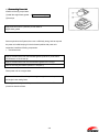
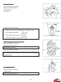
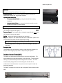
OUTBOARD
SERVICE MANUAL
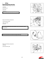
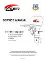
50/40Horsepower
• Two stroke Low pressure
• Direct Injection (TLDI)
• Multi-fuel
• Submersible
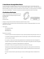
This manual has been prepared for the United States Guardian Angels for
service of the Multi-fuel, Submersible Outboard motor designed and manufactured
under Contract No. N61331·11·C-0008, dated 3/4/11. The data presented in this
manual was revised as of August 2013 representing the latest revision.
August 2013
Copyright© 2013 RAIDER Outboard, Inc. All rights reserved. No part of this manual may be reproduced or transmitted in
any form or by any means without the express written
written permission of Robotics and Conceptual Engineering,
Engineering, Inc. (RaCE).
RaCE.makes
RaCE.makes no warranty, express or implied, regarding the use of this data. RaCE assumes no responsibility for errors
or omissions nor assumes any liability for damages resulting from the use of the information contained herein. In some
cases, a part design may have changed since this manual was published or may not apply to your particular engine
model, or a service/parts bulletin may have been issued containing important information pertaining to this model and/or a
particular part. Some parts may be serial number and/or model number specific. This manual was created
created in Contractor
format per contract.
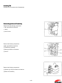
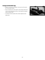
The 50 hp and 40 hp RAIDER outboards was designed and built for the U.S. military developed from a
Mercury/Nissan/Tohatsu production product.
product. Parts can be found worldwide common with these three motors.This
motors.This manual
represents the production version of the Raider outboard motors. Both outboards are capable of burning multiple fuels;
fuels;
that include JP5/8;
JP5/8; kerosene, diesel, and gasoline. The Raider Outboards are design,
design, built for total submersion for
extended
extended periods, and come equipped with dewatering valves.
valves. The outboards are designed for missions from submerged
submarine or airdrop and specifically designed for the Rubber Inflatable Boat (RIB).
(RIB). The RAIDER outboard is available
with a battery located under the cowling for quick starting in extremely
extremely cold conditions or for quick response to a mission
after submersion.
submersion. This battery option is a special order item. The
The basic Raider does not contain a battery.
battery. A pull start is
is
the primary starting device with a rope backup for emergencies.
emergencies.
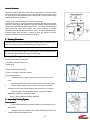
! General Safety Warnings
When replacement parts are required, use genuine RaCE or Mercury,
Nissan, Tohatsu parts with equivalent characteristics including type,
strength, and material. Failure to do so may result in product malfunction
and possible injury to the operator and/or passengers.
To prevent possible eye injury, always wear SAFETY GLASSES while
servicing the unit.
Always read and follow safety related precautions found on containers of
hazardous substances like parts cleaners, primers, sealants, and sealant
remover.
The engine cover is a machinery guard. Use caution when conducting tests
on running engines. Do not wear jewelry or loose clothing. Keep hair,
hands, and clothing away from rotating flywheel.
Replace any locking fastener (locknut or patch screw) if it’s locking feature
becomes weak. Definite resistance to tightening must be felt or locking
fastener is not suitable for continued use. Replace only with authorized
replacement part or equivalent.
When using shop air for cleaning or drying parts:
•
Be sure air supply is regulated to not more than 25 PSI (172 kPa).
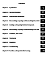
CONTENTS
Chapter 1
Specifications
1
Chapter 2 - Servicing Information
2
Chapter 3
Inspection and Maintenance
3
Chapter 4
Disassembling, Inspecting and Reassembling Power Unit
4
Chapter 5
Installing and Inspecting Electrical Components
5
Chapter 6
Disassembling, Inspecting and Reassembling Lower Unit
6
Chapter 7
Installation;
Installation; Trim and Tilt
7
Chapter 8
Tiller Handle
8
Chapter 9
Dewatering
9
Chapter 10 Troubleshooting
10
Chapter 11 Test Run and Inspection After Servicing
11
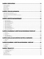
CHAPTER 1 SPECIFICATIONS
SPECIFICATIONS ................................................................
................................................................................................
.................................................................
.................................1-1
1. SPECIFICATIONS TABLE ..................................................................................................................................................................1-1
2. OUTLINE DIMENSIONS ..................................................................................................................................................................1-2
3. WHAT IS TLDI? ..........................................................................................................................................................................1-4
4.FUEL SUPPLY SYSTEM .....................................................................................................................................................................1-7
5.AIR SUPPLY SYSTEM.......................................................................................................................................................................1-8
6. OIL SUPPLY SYSTEM ......................................................................................................................................................................1-9
CHAPTER 2 -SERVICING INFORMATION
INFORMATION ................................................................
.................................................................................
.................................................2
.................2-1
1. GENERAL PRECAUTIONS FOR SERVICING .............................................................................................................................................2-2
2.SPECIFICATIONS AND STANDARDS USED IN SERVICING ............................................................................................................................2-3
3.LISTS OF POINTS FOR APPLYING SEALANT, ADHESIVE AND LUBRICATION .....................................................................................................2-9
4. TORQUE TABLE ..........................................................................................................................................................................2-15
5. SPECIAL TOOLS ..........................................................................................................................................................................2-16
CHAPTER 3 INSPECTION AND MAINTENANCE ................................................................
.......................................................................
.......................................3
.......3-1
1.
2.
3.
1.
2.
3.
4.
5.
6.
7.
8.
PERIODIC INSPECTIONS ..............................................................................................................................................................3-2
INSPECTING ENGINE OIL SYSTEM ..................................................................................................................................................3-3
INSPECTING FUEL SYSTEM...........................................................................................................................................................3-3
INSPECTING COMPRESSION SYSTEM ..............................................................................................................................................3-4
INSPECTING GEAR CASE AREA .....................................................................................................................................................3-6
WASHING PROCEDURE ..............................................................................................................................................................3-8
INSPECTING COOLING SYSTEM .....................................................................................................................................................3-8
INSPECTING TILT SYSTEM ..........................................................................................................................................................3-12
INSPECTING AIR RAIL PRESSURE .................................................................................................................................................3-12
INSPECTING THE DEWATERING SYSTEM ........................................................................................................................................3-12
INSPECTING BATTERY SYSTEM....................................................................................................................................................3-12
CHAPTER 4 DISASSEMBLING,
DISASSEMBLING, INSPECTING AND REASSEMBLING
REASSEMBLING POWER UNIT ..................4
..................4-1
1.
2.
3.
4.
5.
POWER UNIT ..........................................................................................................................................................................4-2
PERIPHERAL PARTS ...................................................................................................................................................................4-7
FUEL SYSTEM ........................................................................................................................................................................4-25
THROTTLE MECHANISM ...........................................................................................................................................................4-37
DISASSEMBLING ENGINE BLOCK .................................................................................................................................................4-41
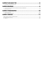
CHAPTER 5 INSTALLING AND INSPECTING ELECTRICAL
ELECTRICAL COMPONENTS..............................
COMPONENTS ..............................5
..............................5-1
1.
2.
WIRE ROUTING .......................................................................................................................................................................5-2
ASSEMBLY ............................................................................................................................................................................5-17
CHAPTER 6 DISASSEMBLY,
DISASSEMBLY, INSPECTION AND REASSEMBLY
REASSEMBLY LOWER UNIT..........................
UNIT ..........................6
..........................6-1
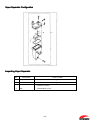
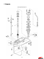
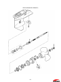
1. CONFIGURATION ......................................................................................................................................................................6-2
2. DISASSEMBLY ..........................................................................................................................................................................6-4
3. INSPECTION ................................................................................................................................................................................6-7
4. REASSEMBLY .........................................................................................................................................................................6-10
CHAPTER 7 TRIM AND TILT
TILT ................................................................
................................................................................................
.....................................................................
.....................................7
.....7-1
1. MOTOR OPERATING INSTRUCTIONS ..............................................................................................................................................7-2
2. AFTER RAIDER IS STARTED .........................................................................................................................................................7-3
3. STOPPING RAIDER ..................................................................................................................................................................7-4
4..OVERHEATING .............................................................................................................................................................................7-6
5. EMERGENCY STARTING ..................................................................................................................................................................7-6
6.PRE-SUBMERSION PROCEDURE ........................................................................................................................................................7-8
CHAPTER 8 TILLER HANDLE
HANDLE TYPE ................................................................
.........................................................................................
.........................................................8
.........................8-1
1.
TILLER HANDLE, SHIFTER AND EMERGENCY STOP .............................................................................................................................8-2
CHAPTER 9 DEWATERING ................................................................
................................................................................................
......................................................................
......................................9
......9-1
1.
2.
LOCATION OF THREE DEWATERING VALVES THE OPERATOR MUST OPEN AFTER SUBMERSION. .......................................................................9-2
DE-WATERING PROCEDURE ........................................................................................................................................................9-3
CHAPTER 10 TROUBLESHOOTING
TROUBLESHOOTING ................................................................
.......................................................................................
.......................................................10
....................... 1010-6
1.
2.
TROUBLESHOOTING TABLE ........................................................................................................................................................10-7
TLDI – SELF DIAGNOSING FUNCTIONS .......................................................................................................................................10-19
CHAPTER 11 SERVICING................................
SERVICING ................................................................
................................................................................................
.......................................................................
.......................................11
....... 1111-1
1. GENERAL OVERVIEW- SERVICING THE RAIDER OUTBOARD ....................................................................................................................11-2
·2.TEST RUNTANK ANDTEST PROPELLER ..............................................................................................................................................11-2
3. INSPECTION ..........................................................................................................................................................................11-3
Chapter 1 Specifications
1
1. SPECIFICATIONS TABLE ..................................................................................................................................................................1-1
2. OUTLINE DIMENSIONS ..................................................................................................................................................................1-2
3, WHAT IS TLDI? ..........................................................................................................................................................................1-4
4.FUEL SUPPLY SYSTEM .....................................................................................................................................................................1-7
5.AIR SUPPLY SYSTEM.......................................................................................................................................................................1-8
6. OIL SUPPLY SYSTEM ......................................................................................................................................................................1-9
1-1
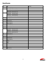
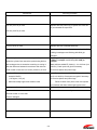
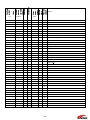
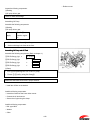
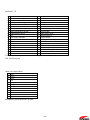
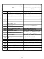
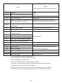
1. Specifications Table
ITEM
RAIDER 50 HP TLDI
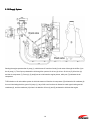
Overall length
1120 mm (44.1 in.)
Overall width
384 mm (15.1 in.)
Overall height
1514 mm (59.6 in.)
Weight
92.0 kg (203 lbs.) – w/o composites/w/o starter & battery
Transom length
530 mm (20.9 in.)
Engine type
2-Stroke Direct Injection
Piston Displacement
697 ml (42.5 cu. In.)
Bore and Stroke
68 mm (2.68 in.) x 64 mm (2.52 in.)
Number of cylinders
3
W.O.T.
5150 – 5850 rpm
Trolling
700/800/900 rpm – 3 stages available
Idling
700/800/900 rpm - 3 stages available
Full throttle fuel consumption (approximately)
17 L/Hr (4.5 US gal/Hr) varies per fuel selection
Starting System
Pull Start; rope backup; under cowling battery optional
Intake System
Reed Valve
Scavenging system
5-port loop Charge
Exhaust system
Through hub
Lubrication system
Oil injection
Cooling system
Water-cooling
Water temperature control
Thermostat (with pressure relief valve)
Ignition System
Inductive
Ignition timing control
Electronics Control Unit (ECU)
Firing Order
1-2-3
Spark Plug
NGK: PZFR6H
Alternator
12V 280W (Maximum)
Battery
Not required; option available – under cowling
Trim Angle
4-24 degrees
Trim Angle settings
6 degrees
Maximum tilt-up angle
75 degrees
Transom board thickness
31-70 mm (1.22 – 2.76 in.)
Maximum steering angle
80 degrees
Gear shift
Dog clutch (F-N-R)
Gear ratio
1:85 (13 : 24)
Throttle Control
Tiller Handle
Fuel Tank
Bladder or tank Furnished by customer – normal fitting
Oil Tank
2L (2.1US qt.)
Fuel
JP5/8/diesel/kerosene/gasoline
Engine Oil
Genuine MD Gold or Equivalent
Gear Oil
API GL5, SAE#80 to #90 500 ml (16.89 fl. Oz.)
Submersibility
66 ft/18 hours-Tested
Handling/grab rails
Yes. Fits through submarine hatch
1-1
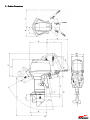
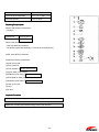
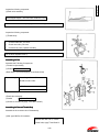
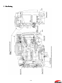
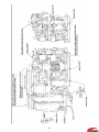
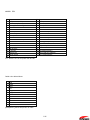
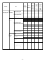
2. Outline
Outline Dimensions
1-2
External Dimensions
Item
50A
A
495 mm (19.5 in)
B
C
Remarks
Transom (5)
728 mm (28.7 in)
Transom (L)
855 mm (33.7 in)
Transom (UL)
982 mm (38.7 in)
Transom (S)
403 mm (15.9 in)
Transom (L)
530 mm (20.9 in)
Transom (UL)
657 mm (25.9 in)
D
568 mm (22.4 in)
E
680 mm (26.8 in)
F
85 mm (3.3 in)
G
600 mm (23.6 in)
H
520 mm (20.5 in)
I
440 mm (17.3 in)
J
31-70mm (1.2-2.8 in)
K
490 mm (19.3 in)
L
Transom (5)
800 mm (31.5 in)
Transom (L)
910 mm (35.8 in)
Transom (UL) 1025 mm (40.4 in)
Ml
384 mm (15.1 in)
M2
345 mm (13.6 in)
N
310mm (12.2 in)
0
235 mm (9.3 in)
P
565 mm (22.2 in)
Q
l2odeg.
R
l2deg.
S
35deg.
T
75deg.
U
161 mm (6.3 in)
Y
54mm (2.1 in)
1-3
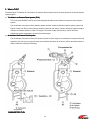
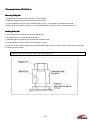
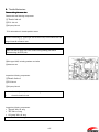
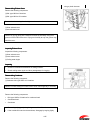
3. What is TLDI?
The abbreviation TLDI stands for Two-stroke Low-pressure Direct Injection and is the name applied to direct fuel-injection
system engines.
a) TwoTwo-Stroke LowLow-Pressure Direct Injection (TLDI)
TLDI is the name RAIDER uses for two-stroke engines that utilize the air-assisted, low-pressure direct injection
system.
The air-assisted, low-pressure direct injection system has been combined with the Inductive ignition system and
Engine Control Unit (ECU), which performs precision control of fuel mixture, injection timing and ignition timing to
maximize combustion efficiency in the TLDI engine. The result is better fuel economy, and low emission
maintaining superior advantage of powerful two-stroke engine.
b) AirAir-Assisted LowLow-Pressure Direct Injection
The air-assisted, low-pressure direct fuel injection process involves using an air compressor to pressurize the fuel
supplied by the fuel pump to inject it directly into combustion chambers in the form of a finely atomized mixture to
achieve maximum combustion efficiency.
Engine with
CARBURETOR TLDI
1-4
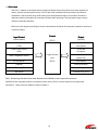
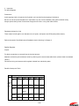
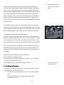
c) ECU Control
With TLDI, a network of connected sensors enables the Engine Control Unit (ECU) to precisely regulate fuel
mixture, injection rate and ignition timing. The ECU also uses a stratified fuel feed process to provide lean
combustion in the low-speed range, while utilizing more homogenized change to ensure the fuel mixture is
distributed uniformly throughout the combustion chamber when operating in the high-speed range to ensure
maximum combustion efficiency.
Below is a block diagram of the Engine Control Unit that allows the Raider 50 horsepower outboard to function as
a multi-fuel engine.
Input Control
Control
Output
(Sensor/Switch)
(ECU)
(Actuator)
Throttle-Position Sensor
#1, #2 
(TPS)
Fuel injectors
Crank-Position Sensor
#1, #2 
(CPS)
Air injectors
Water-Temperature Sensor
Engine Control
Oil level Sensor
#1, #2 
Unit
Ignition coils
(ECU)
Fuel Selector
Capacitor
Warning indicators
De-Watering Pull
Warning oil
Stop Switch
Fuel-feed pump (FFP)
Note: All warning indicators have been silenced on the Raider to not compromise missions.
RAIDER has also integrated a series of mechanical valves into the TLDI to remove water from the system after
submersion. These valves are detailed in detail in Chapter 7.
1-5
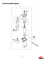
Inductive Ignition System (Requires
(Requires No Battery)
TLDI is nowusing the inductive ignition system to maximize combustion efficiency and fuel economy, and to minimize
exhaust emissions. The ECU inductive ignition system has been modified to support both a higher and longer spark via
the spark plug than conventional TLDI commercial models using L-CDI (Long Arc Duration CDI). This feature was added
to insure a quicker start after submersion than any conventional CDI systems. The improved Inductive Ignition System in
the Raider TLDI engine provides a smoother running outboard than any commercial outboard.
ThrottleThrottle-Position Sensor (TPS)
Throttle-position sensor system is comprised of TPS1 and TPS2. The
twoTPS’s are used in combination to detect throttle butterfly valve position
and advancer arm position and relays the information to the ECU.
CrankCrank-Position Sensor (CPS)
Crank-position sensor is designed to sense the encoder located above the
ring gear on the flywheel in order to detect crankshaft position and
transmit’s the information to the ECU.
WaterWater-Temperature Sensor
Positioned on the water jacket installed on the cylinder,, water-temperature
sensor is used to detect temperature of cooling water in the cylinder and
relay’s the information to ECU.
Oil Level Sensor
Oil level sensor is used to detect the level of remaining oil in oil tank and
relay’s the information to the ECU.
Air Injectors
Air injectors are used to inject a fine mist of fuel and compressed air into
each combustion chamber. The ECU determines the mixture and timing for
injecting fuel according to current engine operating conditions based on
information relayed from the various sensors.
Fuel Injector
Fuel injectors supply the fuel in the air rail to the air injectors via the set
pieces. The ECU determines the mixture for injecting fuel according to
current engine operation based on information relayed from the various
sensors.
1-6
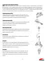
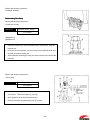
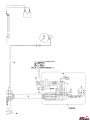
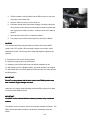
4.Fuel Supply System
Starting the engine activates the fuel pump (3), which draws fuel from the fuel tank (1) and routes it through the fuel filter
(2) to the vapor separator (4). The fuel is pressurized in the fuel-feed pump (FFP) (5); then passes through the highpressure filter (6) to the air rail (7), from there it is injected into the combustion chambers. The fuel regulator (8) regulates
fuel pressure so as to keep it 70 kPa (10 psi)higher than the pressurized air pressure (55OkPa Bopsi)to inject fuel into
combustion chamber after overcoming the air pressure mentioned in “Air supply system” as follows. Any excess fuelis
depressurized and diverted through the FFP case (9) and back to the vapor separator (4). The returned fuel contains air
bubbles left over from being pressurized at (5). These bleed from the top of the vapor separator (4) to the throttle body
(10) and is fed to the air intake system.
1-7
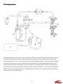
5.Air
5.Air Supply System
Starting the engine operates the air compressor (2), draws air in through the air filter (1) and sends compressed air
through to the air rail (3). The air regulator (4) regulates air at the optimum combustion pressure of 550 kPa (80 psi) and
the regulated air is injected into engine combustion chamber together with pressurized fuel. Any excess air is
depressurized and discharged into exhaust gas (5) from the bottom of the cylinder.
1-8
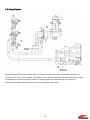
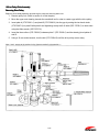
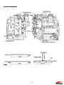
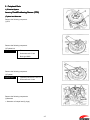
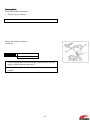
6. Oil Supply System
Starting the engine operates the oil pump (1), which draws oil from the oil tank (2) and routes it through the oil filter (3) to
the oil pump (1). The oil pump channels the oil through four ports to #1 air box (4) air box #2 air box (5), #3 air box (6)
and the air compressor (7). Ports (4), (5) and(6) serve to lubricate the engine pistons, while port (7) lubricates the air
compressor.
TLDI includes an oil recirculation system in which the excess oil from the air compressor (7)is diverted to #3 crankcase (8)
for use in lubricating the drive gear of oil pump (1). Any oil left over from there is diverted to crank upper bearing and #1
crankcase (8), and the crankcase (10) where it is added to oil from (4) and (5) andreused to lubricate the engine.
1-9
1-10
2
Chapter 2 -Servicing Information
2
1.GENERAL PRECAUTIONS FOR SERVICING................................
................................................................
..........................................................................
..........................................2
..........2-1
2.SPECIFICATIONS AND STANDARDS USED IN SERVICING ...................................................
...................................................2
...................2-3
3.LISTS OF POINTS FOR APPLYING SEALANT, ADHESIVE AND LUBRICATION ......................2
......................2-9
4.TORQUE TABLE ................................................................
................................................................................................
..................................................................................
..................................................2
.................. 2-15
5.SPECIAL TOOLS ................................................................
................................................................................................
.................................................................................
.................................................2
................. 2-16
2-1
2-2
2-1
1. General Precautions for Servicing
Users of this manual should observe the following general precautions when conducting disassembly
disassembly and assembly
work.
(1) Make sure that the outboard motor is securely mounted on a work stand before starting work.
(2) Take care not to scratch or damage painted surfaces and the mating surfaces where cylinders, the cylinder head, the
crankcase and other parts are joined.
(3) Always replace packing, gaskets, 0-rings and split pins with new ones when reassembling engine parts. Make a point
of replacing snap rings as well.
(4) When replacing, be sure to use genuine Raider brand parts and lubricants or products recommended by RAIDER.
(5) Always use the recommended special tools to ensure work is done properly.
(6) When disassembling and assembling components, make note of position marks, adding your own marks if none are
provided, as a way to ensure the various parts and components are properly mated when being reassembled.
(7) To prevent smaller parts, such as bolts, nuts and washers from getting lost or damaged, where possible, lightly insert
or tighten them back in their original locations.
(8) As normal practice, check disassembled parts for any wear or damage by first wiping them clean; then washing them
in solvent.
(9) With reassembly operations it is essential to observe precise detail in centering, vacuum sealing, lubricating (with oil
or grease), packing parts and components, and connecting wiring and piping. Also ensure there are no blockages in
fluid lines.
1) When reassembling parts requiring numerous nuts and bolts (cylinder, crankcase etc.), begin by alternately
tightening diagonally opposed inner bolts, moving in a concentric circle; then tightening the outer bolts. This will
ensure that engine parts are assembled evenly and securely. (Use the same procedure in the reverseorder when
disassembling.)
2) When installing oil seals, be careful not to scratch or reverse the sides that mate with the shaft and always apply
grease to the lip surfaces.
3) Confirm the correct quantity and thickness when applying sealant. Applying excessively will result in the excess
portion being excreted into or outside of the case, potentially causing damage. Adhere strictly to the written
instructions when applying adhesives.
4) Apply penetrating oil spray to nuts or bolts that are difficult to remove due to rust and wait 5 minutes before
removing.
5) For the various inspection specifications, torque values, special tools, and the points where sealant, adhesive and
grease are to be applied, refer to the relevant tables.
6) The various nuts, bolts and washers referred to in this manual are various nuts, bolts and washers referred to in
this manual are listed below.
Name Type
Diameter
Length
H820
Hexagon bolt
8mm
N8
Hexagonnut (
8mm
L8
Hexagon nut
8mm
W8
Plain washer
8mm
Spring washer
8mm
Pan head screw
6mm
SW8
Screw 620
2-2
20 mm
20mm
(10)Observe all necessary safety procedures to prevent accidents and injury during work operations.
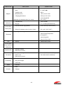
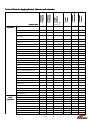
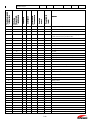
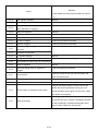
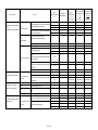
2.Specifications
2.Specifications and Standards Used in Servicing
Name of Part
Item to check
•
Piston
Standard values
Outer diameter
•
67.96 mm (2.676 in)
•
Top: 0.22 to 0.37 mm
Measure at a point 12 mm (0.47 in) above the
lower edge of the piston skirt.
•
Ring end gap
Note: If a ring gauge is unavailable, measure
Piston ring
the lower end of the cylinder bore.
(0.009 to 0.01 45 in)
•
Second & third:0.33 to 0.48 mm
(0.013 to 0.019 in)
•
Deflection
•
0.05 mm (0.002 in)
•
0.03 mm (0.0012 in) or less for
Measure with both ends supported on V
Crankshaft
blocks.
Connecting rod
•
Deflection
•
Mating surface
scratches
Cylinder head
•
Cylinder
Mating surface
•
Cylinder liner scratches and wear
•
Compression
•
0.03 mm (0.0012 in) or less for distortion
•
0.03 mm (0.0012 in) or less for scratches
•
0.03mm (0.0012 in) or less for distortion
•
830 KPa (8.5 kg/cm2, 120 psi)
•
9.3 to 9.5 mm (0.366 to 0.374 in)
•
0.5 ohm ±10% (20’C, 68~F)
•
13.5 k ohm ±20% (20°C, 68°F.)
Measure after warning:
Remove all 3 spark plugs.
Engine block
Remove air injector and fuel injector
connectors.
Reed valve stopper
•
Lift height
•
Fails to close, isworn or damaged
•
Primary coil resistance (between black L-
Reed valve
B/R,B/W,B/G lines)
.
Ignition coil
•
Secondary coil resistance (between spark
plug cap terminal and B line)
ECU
•
Low-speed ESG trigger
•
Approx. 3,000 rpm
•
High-speed ESG trigger
•
Approx. 6,000 rpm
2-3
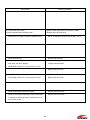
Service limit
Servicing procedure
• 0.8 mm (0.031 in) or more
• Replace with new piston ring if cylinder liner wear has
not yet exceeded the repair limit.
• 0.9 mm (0.035 in) or more
• 0.05 mm (0.002 in) or more
• Replace with new crankshaft.
• 2 mm (0.08 in) or more
• Replace with new crankshaft assembly.
• Scratch depth or distortion is 0.03 mm (0.0012 in) or more
• Repair by polishing the surface plate, starting with #240
to #400 grit sandpaper and finishing with #600 grit
sandpaper.
• When the cylinder liner cannot be repaired using #400 to
• Repair by polishing the surface plate, starting with #240
to #400 grit sandpaper and finishing with #600 grit
sandpaper.
#600 sandpaper due to excessive scratching or scoring or
• Bore and hone to 068.55 (2.699 in) + 0 to 0.02 mm (0 to
when the difference between the maximum and minimum
0.0008 in). Check ports and grind if necessary.
points of wear in liner bore is 0.06 mm (0.0024 in) or more
Use oversize pistons and piston rings.
1)
When difference in compression between cylinders
1)
exceeds lOOKPa
mm (0 to 0.0008 in). Check ports and grind if necessary.
(1.05 kg/cm2, 14.5 psi)
Use oversize pistons and piston rings.
When abnormally higher than standard value
2)
• Scratch depth or distortion is 0.03 mm (0.0012 in) or more
2)
Bore and hone to 068.55 (2.699 in) + 0 to 0.02
Remove carbon from piston crown and cylinder
head surfaces and clean exhaust gas bypass valve.
• No longer conforms to standard value
• Replace with new part.
• Valve reed fails to close
• Replace entire valve assembly.
• Excessive wear on valve seat
• Valve is damaged
2-4
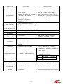
Name of Part
Item to check
•
Magneto
Standard values
Sparking performance Measured using spark
•
10 mm (0.39 in) or more at 350 rpm
tester
•
#1
•
Sparking order
•
280 W
•
Alternator (max.)
•
1,500 rpm l2V 16.5A
•
Charging performance
•
5,500 rpm 12V 18.5A
•
0.44 Ω ohms ±15%
• Alternator coil resistance value (Y to Y wire)
Spark plug
Crank position
sensor (CPS)
#2
#3
(20°C, 68°F)
•
• Standard plug
•
.
•
Plug gap
•
0.7 ~ 0.8 mm (0.0276 0.0315 in)
•
Gap with encoder ring (flywheel)
•
0.5 to 0.9 mm (0.019 to 0.035 in)
•
Pickup coil resistance value (L wire to G wire)
•
5311_ ± 15~ (20°C, 68°F)
•
Opening and closing of thermostat valve
•
Valve start temperature: 52°C (125.6°F)
•
Valve full-open temperature:
Thermostat
NGK: PZFR6H
65°C(149.0°F)
•
Valve full-open lift:
3mm (0.12 in) or more
Fuse
•
Capacity
Pump impeller
•
Wear and cracks
•
Damage to bearing
•
Wear on lip of oil seal
•
Damage to bearing
•
Shaft run-out
•
Wear on lip of oil seal
•
Damage to pull knob
•
Rod gets damaged
•
Valves stick
•
Corrosion
•
Wear
•
Damage
•
15A X 1, 25Ax1, 30A xl
•
0.3 mm (0.012 in) or less (Using
Pump case liner
Guide plate
Propeller shaft
Drive shaft
De-Watering
Anode
Oil seals
both center holes for reference)
2-5
Service limit
Servicing procedure
1) 1.0 mm (0.047 in) or more
1) Repair so that plugs conform to standard values.
2) When electrodes show excessive wear
2) Replace with new spark plug.
•
When sensor no longer conforms to standard value
•
Repair so that sensor conforms to standard value.
•
When fuse burns out
•
Replace with new fuse.
•
When the tips, and upper and lower surface lip areas
•
Replace with new assembly.
show wear, cracks or damage
•
Replace with new shaft.
•
Replace with new shaft.
•
When depth of wear is 0.1 mm (0.004 in) or more
•
0.4 mm (0.016 in) or more
•
Repair so that shaft conforms to standard values.
•
When depth of wear is 0.1 mm (0.004 in) or more
•
Replace with new shaft.
•
When anode shows excessive corrosion
•
Replace with new anode.
•
When lip area shows deterioration, heat discoloration
•
Replace with new oil seal.
or damage or when wear reduces interference to 0.5
mm (0.02 in) or less
2-6
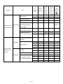
Name of Part
Manual Trim and Tilt
Item to check
Standard values
Tilt Cylinder
•
19600 to 24500 kPa
•
Cylinder bore
•
39.00 to 39.02 mm (1.53 to 1,54 in.)
•
Piston diameter
•
38.97 to 38.99 mm (1.534 to 1.535 in.)
Measure at a point 10 mm above the
•
Top: 0.10 to 0.25 mm (0.004 to 0.098 in.)
lower edge of the piston skirt
•
Second: 0.10 to 0.25 mm (0.004 to 0.098 in)
•
Piston ring and gap
•
0.2 mm (0.008 in) or less
•
Reed valve tip clearance
•
Drive belt
Vapor Separator
•
Wear and damage on seal ring
•
Float
Fuel Feed Pump (FFP)
•
Wear and damage on seals and
Air rail
•
Wear and damage on O-rings
Air regulator
•
Air pressure
•
550kPa (5.6 kg/cm2) +/- 7% (80 psi +/- 7%)
•
Fuel pressure
•
Measured air pressure + 70 kPa (0.7
Air Compressor
Fuel regulator
Air injector
grommets
kg/cm2) +/- 10% (10 psi +/- 10%)
•
Measured value for resistance
•
Operating condition (check for
•
1.29 +/- 0.1 ohm (20 deg. C, 68 deg. F)
•
1.8 +/- 0.1 ohm (20 deg. C, 68 deg. F)
clicking sound when 12 volts is
applied)
Fuel injector
•
Measured value for resistance
•
Between upper and lower connectors: 5.0
ohms +/- 20%
Throttle position sensor
•
(TPS)
•
Measured values of resistance
Between upper and middle connectors:
resistance value (k ohms)
between connectors.
TPS 1
Water Temperature
•
Measured values of resistance
•
Fully closed (
Full Open
0.5 to 1
4 to 5
2.6k ohms +/- 10% (20 deg. C; 68 deg. F)
0.3 k ohms +/- 5% (80 deg. C; 176 deg. F)
sensor
Oil Level sensor
•
Conductivity
Rectifiers
•
Conductivity
•
2-7
Refer to tester checkpoint Table (Chapter 5)
Service limit
Servicing procedure
• When parts no longer conform to standard values
• Replace with new parts.
• When parts show excessive wear or damage
•
Replace with new parts.
• When parts show excessive wear or damage
•
Replace with new parts.
• When parts show excessive wear or damage
•
Replace with new parts.
• When parts no longer conform to standard values
•
Replace with new parts.
• When parts no longer conform to standard values
•
Replace with new parts.
• When parts no longer conform to standard values
•
Replace with new parts.
• When parts no longer conform to standard values
•
Replace with new parts.
• When parts no longer conform to standard values
•
Replace with new parts.
• When parts no longer conform to standard values
•
Replace with new parts.
• When short occurs in sensor
•
Replace with new parts.
•
Replace with new parts.
• When parts show excessive wear or damage
•
When parts showed deterioration or contamination by fuel
• When differences u~ resistance values between upper,
middle and lower connectors becomes erratic
2-8
1342
1373B
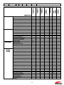
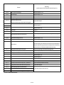
Application points
Engine block
Adhesive 648
518
Piston
Piston pin
Piston ring
Cylinder liner
Pulley nut
O
O
Small-end bearing
Big-end bearing
Main bearing
O
Big-end bearing washer
Main bearing, upper
Main bearing, upper oil seal
Crankcase head O-ring
Crankshaft oil seal, lower ,
Drive shaft oil seal
Oil pump for drive gear
Oil pump for driven gear
O
Cylinder-crankcase mating surface
Water temperature sensor
Spark plug cap
Reed valve assembly bolt
O
Advancer arm
Throttle cam
Throttle cam bolt
O
Clutch arm
Ball joint gap
Cable joint (clutch)
Steering bar
Grip
handle
Bushing A
specifications
Bushing B
Washer
Wave washer
Throttle shaft bushing
Shift lever shaft bushing
Seal ring
Wave washer
2-9
G17
Adhesive
Three Bond
Instant Adhesive
1741
Primer 7471
Drive pulley
Three bond
Sealant
Locitite
Adhesive
Locitite
Thread Lock
Three bond
Thread Lock
Three bond
3.Lis
3.Lists
Lists of Points for Applying Sealant, Adhesive and Lubrication
LT-2
LOR#101
Remarks
fluid #1
Power trim & tilt
gear oil
Specified
Shinetsu grease
Silicon grease,
2st engine oil
OBM grease
resistant grease
cold-Research cold
Oil Center
Lithium grease
Cold & Heat resistant
Shift lever stopper
KS-64
O
Ring groove, piston pin hole and skirt
O
Skirt
O
Inwall
Apply Loctite 648 to the punched side after applying
primer to the shaft and punched surface
O
Sliding surface
O
Sliding surface
O
Sliding surface
O
Sliding surface
O
Lip area
O
Lip area (on oil seal in crankcase head)
O
Lip area (on oil seal in crankcase head)
Confirm thickness of coating
O
0-ring
Plug seat and high tension cored
O
Sliding surface
O
Sliding surface
O
Sliding surface
O
Sliding surface
O
Sliding surface
O
Sliding surface
bO
aO
a) Terminal, b) Pinion
O
Terminal
O
Terminal
O
O
O
O
O
O
O
O
2-10
1342
1107
Air compressor
FFP assembly
Gear case &
Driveshaft
housing
Air injector 0-ring
Fuel injector 0-ring
Fuel regulator 0-ring
Air regulator 0-ring
Compressions seal
Spark plug 0-ring
Air hose L nipple 0-ring
Fuel hose L nipple 0-ring
Valve assembly
Air compressor piston
Air compressor cylinder
Air compressor piston pin
Air compressor piston ring
Air compressor oil ring
Big-end needle bearing
Compressor housing oil seal
Compressor crankshaft BIG
Adapter hose joint
Adapter hose joint
Cable Terminal grommet
FFP upper grommet
FFP lower grommet
Pipe grommet
Gear B nut
Propeller shaft housing
Propeller shaft housing 0-ring
Propeller shaft oil seal
Propeller shaft
Propeller stopper
Propeller thrust holder
Water pump case, lower
Water pump case (lower) 0-ring
Water pump case (lower) oil se~
Pump case bolt
Water pipe
Water pipe seal rubber, upper
Water pipe seal rubber, lower
Water pipe seal lock rubber
Pump case
Engine base gasket
Engine base seal rubber
Exhaust housing grommet
Idling port grommet
Trim tab retainer bolt
Drive shaft
Adhesive 64B
518
1741
Adhesive
Three Bond
Adhesive
Instant
Three bond
Locitite Sealant
Adhesive
Locitite
Thread Lock
1373B
Application points
Air rail
Three bond
Thread Lock
Three bond
Thread Lock
Three bond
O
G17
Primer 7471
O
O
O
O
O
O
O
O
O
O
2-11
O
O
LOR#101
O
& tilt fluid #1
Power trim
grease
Specified gear oil
Shinetsu
Silicon grease,
2st engine oil
OBM grease
grease
resistant
cold-Research cold
Oil Center
grease
Cold & Heat
Resistant Lithium
LT-2
KS-64
Remarks
O-rings at 2 locations
O
O-rings at 2 locations
O
O-rings at 2 locations
O
O-rings at 2 locations
O
Air rail, 6 locations
O
Air rail, 3 locations
O
O-rings at 2 locations
O
O-rings at 2 locations
O
Taper screw
O
Entire outer surface
O
Entire outer surface
O
Apply when inserting pin
O
Entire outer surface
O
Entire outer surface
O
Rollers
O
Inner and outer area of lip
O
Rollers
O
Embedded section (M1OPI.0)
O
Embedded section (M1OPI.0)
O
Both inner and outer surfaces
O
Both inner and outer surfaces
O
Both inner and outer surfaces
O
Both inner and outer surfaces
Apply after cleaning all grease from threading
O
Lower inner surface
O
O
Lip surface
O
Spline surface
O
Tapered surface
O
Spline Surface
O
Lower inner part
O
O
Lip surface
O
Under-neck surface
O
Upper surface
O
Exterior
O
a) Pump case, b) Interior
O
Entire surface
O
Lightly on inner surface
O
Apply to one of the mating surfaces
Apply to one of the mating surfaces
O
O
Apply to engine side spline
2-12
Gear case
1373B
Adhesive 648
518
1741
Adhesive
Three Bond
Adhesive
Instant
Three bond
Sealant
Locitite
Adhesive
Locitite
Lock
Thread
Three bond
Lock
Thread
Three bond
1342
Application points
G17
Primer 7471
Cam rod bushing
Cam rod bushing O-ring, 2.4 to 5.9
Cam rod bushing O-ring, 3.5 to 21.7
Cam rod bushing stopper bolt
Gear case lubricating oil
Gear case bolt
Extension housing bolt
Propeller shaft housing bolt
Stern bracket section
O
(*2)
Bracket bolt
Bracket bolt cap
Stem bracket washer
Swivel bracket
O
Steering shaft
Steering shaft bushing
Steering shaft seal ring
Thrust plate
Mounting bolt, upper
O
Mounting bracket
Tilt stopper
Motor cover, upper
Filler lid hinge
Hook lever
Hook lever bushing
O
Hook lever seal ring
Filler lid seal rubber
PTT Section
O
PTT cylinder pin, upper
O
PTT cylinder pin, lower
PTT sensor cam bolt
PTT tilt stopper knob
O
PTT oil
Joint Metal
O
O-ring
Yoke O-ring
Tank cap O-ring
pump O-ring
Relief valve O-ring
Reserve tank O-ring
Reserve tank seal
Remote control
Drag link
Control box
Nipples
O
*2 When reinstalling the used bolt the adhesive specified must be applied
2-13
LOR#101
tilt fluid #1
Power trim &
gear oil
Specified
Shinetsu
grease,
Silicon
2st engine oil
grease
OBM grease
cold
cold--resistant
Research
grease
Oil Center
Lithium
Cold & Heat
resistant
LT-2
Remarks
KS-64
O
Entire surface
O
O
O
Under-neck surface
O
Oil capacity 500 ml
O
Under-neck surface
O
Under-neck surface
O
Under-neck surface
O
Fill with grease, apply grease to tapped hole
O
Inner surface
O
Both surfaces
O
Fill interior with grease
O
Sliding surface
O
Sliding surface
O
O
Sliding surface
Thread
O
Spline surface
O
Sliding surface
O
Sliding surface
O
Sliding surface
O
Sliding surface
O
Sliding surface
O
Sliding surface
Use the specified lubricant
O
O
O
O
O
O
O
O
O
O
Sliding surface
O
Each press-in port
2-14
4. Torque Table
Engine
Item
Part to tighten
Initial torque (N-m)
Full torque (N-m)
lb-ft
Cylinder head cover -
Bolt (M6)
①2.0 - 2.9
④4.6 - 6.3 (0.5-0.6 kg-m)
3.6 - 4.4
Cylinder head cover
Bolt (M8)
②12 - 15
③29-34 (3.0 - 3.5 kg-m)
22 - 25
Crankcase
Bolt (M8)
12 - 15
24 - 26 (2.4- 2.6 kg-m)
17 - 19
Exhaust cover
Bolt (M6)
3.9-5.9
7.8 - 9.8 (0.8 - 1.0 kg-m)
5.8-7.3
Compressor head
Bolt (M6)
7.8 - 9.8 (0.8 - 1.0 kg-m)
5.8-7.3
Throttle body
Bolt (M6)
7.8 - 9.8 (0.8 - 1.0 kg-m)
5.8-7.3
Air box
Bolt (M6)
7.8 - 9.8 (0.8 - 1.0 kg-m)
5.8-7.3
-
20 - 23 (2.0 - 2.3 kg-m)
5.8-7.3
Driven pulley
Nut, 10 (M10)
44 - 49 (4.5 - 5.0 kg-m)
5.8-7.3
Drive pulley
Nut pulley (M30)
90 - 110 (9 - 11 kg-m)
15 - 17
Nut, 18 (M18)
140 - 160 (14 - 16 kg-m)
32 - 36
-
14 - 16 (1.4 - 1.6 kg-m)
65 - 80
14 - 16 (1.4 - 1.6 kg-m)
102-116
Water temperature sensor
Flywheel
Adapter, hose joint
Nut, hose joint
-
Valve core
41194
_
0.4 - 0.6 (0.04 - 0.06 kg-m)
Spark plug
25 - 30 (2.5 - 3.0 kg-m)
Power trim and tilt
Lower unit
Cylinder block and
Standard torque
10 - 12
0.3-0.4
Bolt (M8)
19 - 21 (1.9 - 2.1 kg-m)
18 - 22
Bevel gear B
Nut, bevel gear B (M12)
40 - 58 (4 - 6 kg-m)
14 - 15
Stem bracket
Nylon nut 7/8
24 - 26 (2.4 - 2.6 kg-m)
Mount rubber, upper
Bolt (3/8)
30 - 34 (3.0 - 3.5 kg-m)
Mount rubber, lower
Nylon nut (M12)
40 - 44 (4.0 - 4.5 kg-m)
29 - 44
17 - 19
Gear case
Bolt (M8P1.25)
19 - 21 (1.9 - 2.1 kg-m)
22 - 25
Propeller nut
-
29 - 39 (3.0 - 4.0 kg-m)
29 - 33
Fuel connector
-
5.0 - 6.9 (0.5 - 0.7 kg-m)
14 - 15
Ranyard stop switch
-
2.0 - 2.5 (0.2 - 0.25 kg-m)
22 - 29
Reserve tank bolt
Hexagon socket head screw (M5)
4.4 - 4.9 (0.45 - 0.5 kg-m)
3.6 - 5.1
Tank cap
-
0.8 - 1.5 (0.08 - 0.15 kg-m)
1.5 -1.8
Manual valve
-
1.5 - 2.0 (0.15 - 0.2 kg-m)
3.2 - 3.6
Oil pump bolt
Hexagon socket head screw (M5)
4.9 - 5.4 (0.5 - 0.55 kg-m)
0.6 - 1.1
Joint metal
-
39 - 49 (4.0 - 5.0 kg-m)
1.1 - 1.5
Motor bracket screw
-
4.9 - 6.9 (0.5 - 0.7 kg-m)
3.6 - 4.0
M4
1 - 2 (0.1 - 0.2 kg-m)
29 - 36
M5
3 - 4 (0.3 - 0.4 kg-m)
3.6 - 5.1
M6
5 - 6 (0.5 - 0.6 kg-m)
1
M8
11 - 15 (1.1 - 1.5 kg-m)
2-3
M10
23 - 30 (2.3 - 3.1 kg-m)
3-5
8 - 11
17 - 22
Remark: Tightening order of cylinder head cover and cylinder head is ①‣②‣③‣④.
2-15
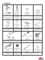
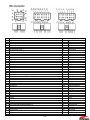
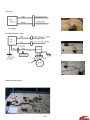
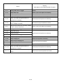
5. Special Tools
2-16
1. List of Special Tool
Pressure gauge assembly
Crimping pliers
Drive pulley press
Piston slider
3T5-72880-O
3T5-72864-O
3T5-72868-O
3T5-72871 -o
For crimping
For measuring air rail fuel and
OETIKER make
air pressure
clamps.
For installing the piston in
For press fitting in the drive pulley.
the air compressor.
0-ring setting tool
Crankshaft holder
(024)
Piston ring wrench
Piston pin tool
3T5-7281 5-0
3T5-72863-O
353-72249-0
345-72215-0
For removing and tightening
For installing 0-rings
For installing and removing the
For installing and
on the pulley nut.
on the fuel injectors.
piston rings.
removing piston pins.
Thumbing
gauge
Filler gauge
3C8-72250-O
353-72251-0
For measuring between bevel gears
For measuring
A and B.
clearances.
Backlash measuring tool
For measuring backlash between bevel gears A and B.
Bevel gear A bearing puller
Bevel gear A bearing
assembly
Setting tool
Bevel gear B nut wrench
Bevel gear B nut socket
345-72224-2
3C8-7271 9-0
346-72231-0
346-72232-0
For removing bearing from
For installing bevel gear
bevel gear A.
A bearing.
For removing and installing bevel gear B nut.
2-17
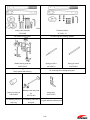
Drive
pulley puller assembly
Flywheel puller kit
3T5-72890
3C7-7221 1-1
For removing drive pulley.
For removing and installing flywheel.
Needle bearing puller kit
Spring pin tool A
Spring pin tool B
3C8-72700-O
345-72227-0
345-72228-0
For removing and installing gear case needle bearing
For removing and Installing spring pins.
and propeller shaft housing.
Clutch pin snap tool
345-72229-0
Bearing Outer race press
3B7-72720-0
3B7-72739-0
For installing clutch pin For installing Outer race of
snap ring,
Clamp ass’y
kit
level gear
For gear backlash measurement
2-18
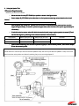
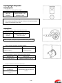
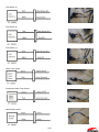
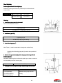
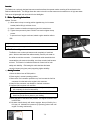
2. Using the Special Tool
Pressure Gage Assembly
Measuring Fuel and Air Pressure
1. Mover the lever for cock (3T5(3T5-7288372883-O) to position A shown in the figure below.
2. Screw adapter
adapter B (3T5(3T5-7288472884-0) into either the air or fuel pressure measuring valves located on the air rail.
Caution:
A small amount of fuel will spurt out as the adapter is inserted in the fuel measuring valve.
3. With the ignition key set the OFF position, turn it to START to activate the starter motor and turn over the
engine for approximately 15 seconds. (Once the engine starts, allow it to idle at 700 rpm for approximately for
15 minutes.)
4. If both fuel and air pressure values fall within the standard (rated) range, engine operation is normal. (If not,
service the engine by referring to the relevant sections in this manual.)
PRESSURE
Rated value (kPa, psi)
Rated range (kPa, psi)
AIR PRESSURE
550, 80
550 ± 30, 80 ± 4
Pressure falls when engine stops turning
FUEL PRESSURE
620, 90
620 ± 30, 90± 4
over.
Remarks
5. When finished measuring, turn the lever to position B (open) to relieve internal pressure;
pressure; then remove adapter
B from the measuring valve.
It is important to have a container handy. Once fuel measuring completes and the lever is set to position B (open), a
certain amount of fuel will spurt out from the hose (98AB-5-0200). Be sure to point the hose (98AH-8-1 000) on the cock
side lower than valve position and drain all remaining fuel prior to removing adapter B.
2-19
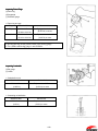
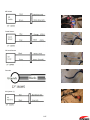
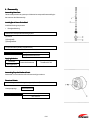
Crankshaft Holder (3T5(3T5-7281 55-0)
Removing Pulley Nut
1. Disassemble the flywheel. (Refer to section of this chapter.)
2. Install the magneto key and crankshaft holder for this engine.
3. Use the magneto nut to secure the crankshaft holder in place. (The magneto nut is threaded clockwise.)
4. Using two 36 mm wrenches, attach one to the crankshaft holder and use the other to loosen the pulley nut.
Installing Pulley Nut
1. Apply thread lock (Three Bond #1342) to the thread area.
2. Screw the pulley nut onto the crankshaft by hand.
3. Install the engine’s magneto key; then install the crankshaft holder.
4. Use the magneto nut to secure the crankshaft holder in place.
5. Using two 36 mm wrenches, attach one to the crankshaft holder and use the other to tighten on the pulley nut, adjusting
it to the torque shown below.
Tightening Torque: 90 to 110 N-m (9 to 11 kg-m) [65 to 80 lb-ft]
2-20
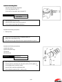
Drive Pulley Puller Assembly
Removing Drive Pulley
Begin the disassembly operation by removing the crankshaft from the power unit.
1. Remove pulley nut. (Refer to section © of this chapter.)
2. Move the upper main bearing towards the crankshaft end in order to create a gap with the drive pulley.
3. Insert plate A (3T5-72891 -0) and plate B (3T5-72892-0) into the gap by mating the two knock studs
(3T5-72897-0) on plate B with plate A and tightening evenly the 8-40 bolts (3B7-72785-0) on both sides
using the Allen wrench (3B7-72787-0).
4. Insert the three collars (3T5-72895-0) between plate C (3T5-72893-0) and the already joined plates A
and B.
5. Using a 19 mm socket wrench, turn the bolt (3T5-72894-0) until the drive pulley comes away.
Note: Apply grease to the sections in the diagram marked by the asterisk (*).
2-21
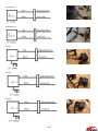
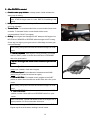
Drive Pulley Press (3T5(3T5-7286872868-O)
Inserting Drive Pulley
1. Remove any oil or grease from crankshaft and drive pulley hole. Apply Loctite Primer 7471; wait 5 minutes;
then apply Loctite 648 to the hole.
2. Insert the half moon key in the crankshaft and install the drive pulley.
3. Position the drive pulley press above the drive pulley.
With the wide-open end of the press facing downward, place down over the drive pulley.
4.
Tapping lightly on the top center area of the press with a hammer, press fit the drive pulley in place. (The
beginning half is designed to insert easily, the remaining half requires press fitting.)
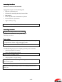
Piston Slider (3T5(3T5-7287172871-O)
Installing Air Compressor Piston
1. Apply sufficient amount of LOR#1O1 and 2-stroke engine oil mixed on a 1:3 ratio to the exterior of the piston, the
interior of the piston slider and the interior of the compressor rings.
2. Place the piston with piston ring installed on the tapered part of the piston slider, lineup the assembly with the top
surface of the cylinder and press piston into the cylinder by hand.
3. Press the piston down in a single firm motion until it is properly inserted.
Note:
If the piston ring should get caught part way through, repeat the operation from step 2.
2-22
0-ring Setting Tool (o24) (3T5(3T5-7286372863-O)
Install the fuel injector 2.8-20.2 0-rings (3T5-1 0304-0).
Apply engine oil to both the 0-rings and the 0-ring setting tool.
Position the 0-ring setting tool in place; then install 0-rings by sliding them on.
..
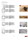
Crimping Pliers (3T5(3T5-7286472864-O)
This tool is used to install the specified clamps on the fuel and air system hoses. It is intended for use with the
1.
following parts.
Fuel Hose Assembly (3T5-1 0089-0)
Clamp 21/32 (385-10086-0): Installed at four locations on the hose connecting FFP case assembly to high-pressure
2.
3.
fuel filter and the hose connecting high-pressure fuel filter to air rail assembly.
Air Hose Assembly (3T5-10088-0)
Clamp 1/12 (3T5-10087-0): Installed at two locations on hose connecting air compressor to air rail assembly.
Clamp 29/64 (3T5-10091-0): Installed at two locations on hose connecting L nipple on air rail to fuel regulator.
Clamp Crimping Procedure
Crimping is performed by applying crimping forced to the locations indicated by arrows in the figure below.
The crimping tool is designed to not open until it has crimped all the way.
Caution:
• Be sure to use new clamps.
• Note that the highly pressurized fuel or high temperature, highly pressurized air flowing through the hoses are liable to
leak if the clamps are not firmly crimped in place.
2-23
2-24
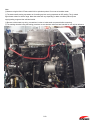
Chapter 3 Inspection
Inspection and Maintenance
3
CHAPTER 3 INSPECTION AND MAINTENANCE
MAINTENANCE ................................................................
.......................................................................
.......................................3
.......3-1
1.
2.
3.
1.
2.
3.
4.
5.
6.
7.
8.
PERIODIC INSPECTIONS ..............................................................................................................................................................3-2
INSPECTING ENGINE OIL SYSTEM ..................................................................................................................................................3-3
INSPECTING FUEL SYSTEM...........................................................................................................................................................3-3
INSPECTING COMPRESSION SYSTEM ..............................................................................................................................................3-4
INSPECTING GEAR CASE AREA .....................................................................................................................................................3-6
WASHING PROCEDURE ..............................................................................................................................................................3-8
INSPECTING COOLING SYSTEM .....................................................................................................................................................3-8
INSPECTING TILT SYSTEM ..........................................................................................................................................................3-12
INSPECTING AIR RAIL PRESSURE .................................................................................................................................................3-12
INSPECTING THE DEWATERING SYSTEM ........................................................................................................................................3-12
INSPECTING BATTERY SYSTEM....................................................................................................................................................3-12
3-1
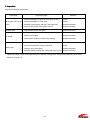
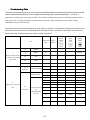
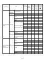
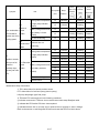
1. Periodic Inspections
Inspections
Category
Inspection intervals
Inspection
10 hrs.
30 hrs
points
or
or
bimonthly
monthly
High press.
Fuel adn compression systems
Fuel filter
O
Piping
100 hrs.
or
or
3
6
months
months
O
O
O
Fuel tank
Yearly
O
1.5
years
O
200 hrs.
or
O
O
Replace
O
O
O
O
O
Replace
Drive belt
O
Replace
O
O
O
O
pressure
.
O
cartridge
Wear on pipes &leaking
connectors
Clean
Including filter
0.7 to 0.8 mm
O
O
O
O
O
Remove carbon Spark gap
system
Pull Start
O
O
O
O
Salt, Corrison
Rope Start
O
O
O
O
Frey in rope
O
O
O
O
Wear, bending &chipping on
O
O
blades; slipping of cushion
Lower unit
Propeller
Gear oil
rubber
Replace
systems
Water pump
O
O
O
O
O
O
O
Replace
O
Replace
Replenish or change oil,check
for water leakage
Wear and cracks on
impeller & liner
Oil tank
O
O
O
O
O
Oil pipes
O
O
O
O
O
Oil filters
O
O
O
O
O
O
O
O
O
O
O
O
O
O
O
O
Tighten
O
O
O
O
Apply or inject grease
O
O
O
O
Warning system
Nuts and bolts
O
O
Oil leaks, damage faulty
clip; wash filter
Sliding & rotating
parts,
grease_nipples
Standard tilt
Anodes
(0.0276 to
0.0315 in)
Spark plug
O
Oil
Remarks
Entire
Replace
O
Fuel
Inspection procedure
2 years
Air filter
Air pressure
Starting Ignition system
50 hrs.
O
O
O
O
O
O
Check & replenish oil;
manually operate
Check for corrosion,
.warping and wear
Note: The manual recommends the engine be overhauled after every 300 hours of operation
3-2
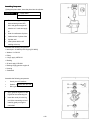
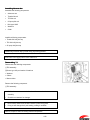
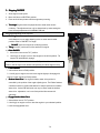
2. Inspecting Engine Oil System
Bleeding Air from Oil Pump
Conduct a visual check of the clear vinyl pipes connecting the oil pump to the
oil tank to inspect for the presence of air. Bleed hoses if necessary.
Do this by loosening the air vent screw
on the air pump and
bleed until all air has been removed from the piping.
Use a cloth to wipe away the bled oil.
Note that the air may not bleed out properly if the oil in the tank is
too low. Make sure to fill the tank prior to bleeding air from the
piping.
Oil Filter and Oil Tank
Check the oil filter for water and foreign matter. If present, disconnect
all piping connecting the oil tank to the oil pump from the outboard
engine and remove all oil and any water or foreign matter. Reconnect
oil tank and add new oil; then repeat the same air bleeding procedure
used on the oil pump
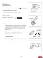
3. Inspecting Fuel System
Replacing Engine Fuel Filter
Fuel filter (Detachable type)
The red ring
floats when
water is present. If it floats,
remove cup and empty out the
water.
High-Pressure Fuel Filter (Disposable type)
Refer to maintenance chart.
3-3
•
Difference between cylinders
Cleaning Bladder/Fuel Tank Filter
①Fuel pickup elbow
②Filter
Turn
to the left to remove and clean②.
Cleaning Bladder/Fuel Tank.(Not
Tank.(Not supplied with RAIDER )
Clean the bladder/fuel tank whenever there is a buildup of water or
foreign matter.
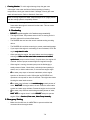
1. Inspecting Compression System
Measuring Procedures
Use the following procedures to measure the compression of the
individual cylinders.
1. Fully charge the engine battery (optional).
exceeds 103 kPa (1.05
2. Start engine and idle for 3 minutes to warm.
kg/cm2, 15 psi)
3. Unlock the stop switch.
•
high.
4. Remove all spark plugs.
5. Remove all air injector ② and fuel injector ③connectors.
Accurate compression readings are only possible when all ②&③connectors
are disconnected. It should also be noted that the ECU records detailed
information on which connectors were disconnected during each inspection.
Refer to the section on the TLDI self-diagnosing function for more information.
6. Attach the compression gauge
into the sparkplug hole (only one at a
time).
7. Use the starter motor to turn over the engine.
Engine speed: approx. 400 rpm for at least 5 seconds
(Note that throttle position does not affect compression
readings.)
•
Measure the compression for all cylinders
•
Confirm that all compression readings conform to specifications.
Rated compression:
830 kPa (8.5 kg/cm2, 120 psi)
±10%
Results and Steps to Take
Repair or replace components as necessary when the readings fall under the
following categories.
•
Compression is abnormally
Below specified compression:
3-4
3-5
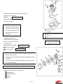
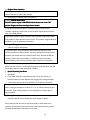
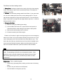
2. Inspecting Gear Case Area
Area
To avoid accidental starting of engine while servicing, twist and
remove all spark plug leads.
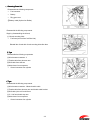
Replacing Propeller
•
Worn or bent propeller blades will not only affect performance and
can also lead to engine damage.
•
Move the shift lever to the neutral position; stop the engine, then replace
the propeller.
•
Be sure to wear a thick pair of gloves and proceed carefully.
Remove the following components
Split pin.
Replace with new pin
Propeller nut
Washer
Propeller stopper or adapter
Propeller or with drive sleeve
Propeller thrust holder or washer
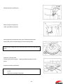
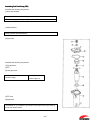
Replacing Gear Oil
Place an oil container under the lower unit and remove the lower
•
oil plug①
•
Remove the upper oil plug ②and sufficiently drain the oil.
•
Insert the gear oil container spigot t③ into the lower oil plug hole and
squeeze the container until oil overflows from the upper oil plug hole④.
Oil:
Genuine gear oil or GL5,
SAE#80, #90
Capacity: 500m1, 16.9 US fI.oz
(approx.)
First tighten the upper oil plug②; then remove the oil container and
reinstall the lower oil plug①.
3-6
3-7
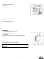
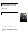
Corrosion Protection
Whenever possible after use in sea water or submersion in sea water, wash
entire engine with fresh water to remove salt deposits and wipe down with a
dry cloth. Spray entire powerhead with a liberal coat of Anti-Corrosion Spray
penetrant/lubricant or equivalent.
Though not specifically mentioned as a service procedure,
Anti-Corrosion Spray or equivalent should be applied after any service repairs
under the engine cover and repeated at regular intervals to protect powerhead
components. Anti-Corrosion Spray leaves a thin, non-messy, transparent film
that actually lifts water and moisture from metal surfaces. It protects
equipment and tools that are left outdoors, even in humid coastal areas. AntiCorrosion Spray dries out ignition systems to start wet engines and stops
moisture-induced short circuits in electrical systems.
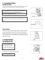
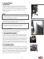
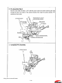
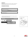
3. Washing Procedure
Take care not to come into contact with the propeller while it is in motion. Be
sure to remove the propeller when operating the engine on land.
Be sure not to operate the engine in confined areas, such as a boat house, as
the exhaust fumes contain toxic carbon monoxide gas.
Washing With Flushing Attachment (Hose adapter)
Remove the following components.
• Propeller and thrust holder, etc.
①Water plug
Install the following components.
②Tape: at 2 locations (on water strainer)
②Flushing attachment
•
Connect a hose to a water faucet and insert the end of the hose
into③
•
Move the gearshift lever to the neutral position and start the engine.
•
Confirm that a steady stream of water is coming from the water
checking port; then operate the engine at low speed for 3 to 5 minutes.
•
Stop the engine, turn off the water supply, remove the flushing
attachment ③and tape, reinstall the water
•
plug① ; then reinstall the propeller assembly.
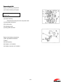
4. Inspecting Cooling System
Thermostat test
•
Place the thermostat into a suitable container and add either cold or
warm water.
•
Heat the water in the container and confirm that the thermostat valve
operates when the temperature rises.
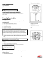
3-8
Valve operation start temperature
52°C ± 1.5°C (126°F ± 3°F)
Valve full open temperature
65°C ± 1.5°C (149°F ± 3°F)
Valve full open lift
3 mm or more
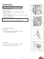
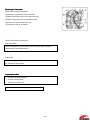
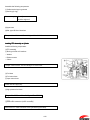
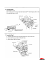
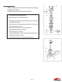
Replacing Pump Impeller
Remove the following components.
① Split pin
Special tool
② Spring tool A
345-72227-0
Remove the following components.
• Bolt: type H835 at 6 locations
• Remove the gear case assembly ③ from the drive shaft housing.
⑤Bolt: type H835 at 4 locations
Inspect the following components.
⑥Upper pump case
⑦Pump case liner
⑧Pump impeller
Replace with new one.
⑨Key for water pump impeller
⑩Gasket for pump case
Replace with new one
⑪Guide plate for water pump
⑫Gasket for guide plate
Replace with new one
⑬Lower pump case
⑭0-ring
⑮Oil seal
Inspection Procedure
⑥- ⑮replace with new components if worn or damaged.
Make sure oil seals ⑮are installed facing in the proper direction.
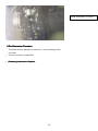
3-9
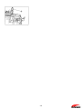
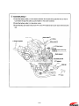
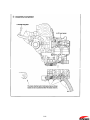
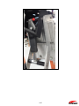
Overview of Cooling System
Tubing
3-10
3-11
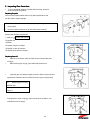
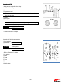
5. Inspecting Tilt System
Checking Lift Cylinder
Note that the lift cylinder is located in the front of the Raider Outboard is
checked by first tilting up the outboard engine to confirm the motor can tilt
easy. The cylinder should work freely. No maintenance can be completed on
this item as it is a replaceable. At the back of the Raider insure all lock
handles work freely.
Caution:
Caution:
In order to avoid damage and accidental injury that can occur when the tilted up
(for storage and inspections etc.) outboard engine accidentally tilts back down,
be use to insert the tilt stopper when tilted up.
Oil Type – Two Stroke Only. Insure oil is full prior to submersion.
Note that the presence of air in the oil can cause the engine harm during
submersion as water could penetrate oil system
With the outboard engine installed on the boat, turn the red knob (counter
clockwise) and move the engine the full tilt up and down stroke 5 or 6 times;
then turn the red knob back to the starting position (clockwise).
6. Inspecting Air Rail Pressure
Refer to the description for ~ Pressure Gauge Assembly, listed under section
5. (Special Tools) in Chapter 2 (Servicing Information).
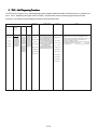
7. Inspecting the Dewatering System
The dewatering system consists of three valves that requiring opening after
submersion. The first valve is located in the back of the Raider Outboard.
Simply lift the lever on the back assembly and turn 1/4 turn to open the valve.
Check to insure the valve turns freely.Inspect the mid valve located on the left
side of the Raider outboard by turning the valve 1/4 turn. The valve should
operate freely. Inspect the front valve to insure it turns freely. Turn the valve
¼ turn counterclockwise. The valve should operate freely. Return to closed
position by turning ¼ turn clockwise.
8. Inspecting Battery System
The battery is located under the cowl behind the flywheel. The battery should
be inspected for corrosion at the positive and negative terminals. The cowling
must be removed for this inspection. The battery is a simple lead acid, sealed,
battery. Test the battery by pushing the starter button located on the front of
the Raider pan. The Raider should turn over freely. Do not start unless in
water. If the motor fails to turn over replace the battery.
3-12
Chapter 4 Disassembling, Inspecting and Reassembling Power Unit
CHAPTER
CHAPTER 4 DISASSEMBLING, INSPECTING
INSPECTING AND REASSEMBLING
REASSEMBLING POWER UNIT ..................4
..................4-1
1.
2.
3.
4.
5.
POWER UNIT ..........................................................................................................................................................................4-2
PERIPHERAL PARTS ...................................................................................................................................................................4-7
FUEL SYSTEM ........................................................................................................................................................................4-25
THROTTLE MACHANISM ...........................................................................................................................................................4-37
DISASSEMBLING ENGINE BLOCK .................................................................................................................................................4-41
4-1
1. Power Unit
Unit
4-2
a) Removing Power Unit
Disassemble the following components.
•
Fuel connector
•
Battery
•
Ring gear cover
④Battery cable (Optional on Raider)
Disassemble the following components.
Begin by disassembling the oil tank;
⑤ Oil tank mounting bolts
•
Fuel hose (remove from fuel filter inlet)
Reinstall the oil tank with oil tank mounting bolts after then.
P Type
Disassemble the following components.
⑧Wire harness connectors: 3
⑨Throttle cable from advancer arm
⑩Shift cable from shift arm
⑫Water hose from compressor
•
Ground connector from cylinder
F Type
Disassemble the following components.
⑧Wire harness connectors: 3 Neutral switch cable
⑨Throttle cable from advancer arm and throttle cable bracket.
⑩Shift cable joint rod from shift arm
⑪“S”- link from throttle stop arm
⑫Water hose from compressor
•
Ground connector from cylinder
4-3
Disassemble apron (splash pan).
Remove engine mounting bolts.
①Bolt: type H880 at 6 locations
Secure eyeboltsto the flywheel; then use a sufficiently strong hoist to
suspend the power unit while keeping it in the horizontal position.
Suspend slowly, taking care not to catch the power unit on any of the wiring or
hoses.
②Remove crankcase head.
Remove with caution by gently
inserting a flathead screwdriver in the
groove
Inspect the following components.
•
Oil seals: at 2 locations
•
0-rings
•
Replace any damaged components.
4-4
4-5
b) Reassembling Power Unit
Install the following components.
①Install the engine base gasket
>Replace with new gasket.
②Knock pin
Apply three bond #1107 (Seal out) to both sides of
engine base gasket
Secure eyebolts to the flywheel; then use a sufficiently strong hoist to suspend
the power unit while keeping it in the horizontal position.with power unit
suspended, install the following components.
•
Crankcase head
Apply a sufficient amount of heat-resistant grease (LOR #101) to the entire
circumference of the oil seal lip.
Apply a sufficient amount of the recommended grease to the 0-rings.
Refer to servicing information (section 3 in chapter 2)
Place power unit on to engine base.
Take care that none of the wiring or hoses gets caught between the power unit
and engine base mating faces.
Referring to section 1), assemble power unit in the reverse order of the
procedures described there.
4-6
2. Peripheral Parts
1) Electrical System
Removing CrankPositioning
Sensor (CPS)
,Flywheel and Alternator
Remove the following component.
①CPS
Remove the following component.
②Flywheel nut
Special Tool
•
Plate
•
Socket wrench: 27 mm
•
Bolt: type M820
Remove the following component.
③Flywheel
Special Tool
•
Flywheel puller kit 3C7-7221 1-1
•
Socket wrench: 19 mm
Remove the following components.
④Alternator
• Alternator coil output lead (3 plugs)
4-7
Remove the following components.
⑦Coil bracket
⑧Cable clamp
Remove the following components.
⑨Solenoid switch bracket
⑩Bolt: type H625 at 3 locations
Removing ECU *
*ECU: abbreviation for the engine control unit.
Remove the following components.
①ECU connector
While pressing down on hook, remove by prying gently with a flathead
screwdriver.
②Rubber mount bolt: type H630 at 3 locations Remove from 2 of the upper 3
locations; then take out ECU by pulling it upwards.
The collar used on the ECU rubber mount differs in length from the one used
on the oil tank.
③Clamp
4-8
Removing Harness Assembly
Remove the following components.
Remove harnesses in order starting from remote control side.
④Water temperature connector
• Remove by pressing down on hook and pulling out connector.
⑤Fuel injector connector
• Remove by pressing down on wire hook and pulling out connector.
⑥Air injector connector
• Remove by pressing open the claws on either side with a flathead
screwdriver and pulling out.
⑦Bullet connectors for ignition coils
When removing cable assembly with the compression head resting on the
engine base, be sure to remove the air rail bolt to free the air rail.
Remove the following components.
⑧FFP*connector
• Remove by pressing down on hook and pulling out connector.
* FFP: abbreviation for fuel-feed pump.
⑨TPS*connector
• Remove by pressing down on hook and pulling out connector.
*TPS: abbreviation for throttle position sensor.
4-9
Removing Ignition Coil and Rectifier Regulator
Remove the following components.
⑩Ignition coil #1
⑪Ignition coil #2
⑫Ignition coil #3
⑬Rectifier regulator
4-10
4-11
2) Air Supply System
Prior to Removing Peripheral Components
(1) Press on the core of the air valve located on the air rail to release
pressure from the air lines.
(2) Press on the core of the fuel valve located on the air rail to
release pressure from the fuel lines.
Be sure to cover the fuel
valve with a clean cloth as
fuel will spurt out when
pressure is released
(3) After loosening the plug on the upper section of the vapor separator
in order to release pressure, loosen the drain plug on the lower
section and drain out the fuel.
Hold a cloth against the
drain plug to absorb the
fuel as it drains out.
4-12
4-13
Removing Air Compressor
Remove the following components.
①Detach the oil pipe on the compressor side.
②Detach recirculation pipe on the compressor side.
③Detach cooling water pipe on compressor side.
④Remove air hose on compressor side.
⑤Compressor bolts: at 3 locations
Remove the following components.
⑥Air compressor
The air compressor is held in place by two knock pins, these should be
removed with a gentle tilting motion
⑦Drive belt
Be sure to apply markings that identify the top and bottom sides in cases when
the drive belt is being reused.
Inspecting Drive Belt
•
Check for wear and damage.
•
Check for missing teeth.
•
Check for presence of oil.
Replace in cases where even the slightest defect is found.
4-14
Air Compressor Configuration
4-15
Inspecting Air Compressor
No.
Component
Piston
Points to check
•
Wear and damage
•
Check outer diameter of piston
•
Connecting rod : Confirm smooth operation
•
Big end bearing : Confirm smooth operation
Piston ring
•
Measure piston ring end gap
Bearing
•
Rotate by hand and check for excessive play and catching
•
Replace with new one if defects are found
•
Be careful not to scratch housing when removing bearing
•
Apply force to outer race when press fitting bearing
•
Wear and damage
•
Replace with new one if defects are found
Oil seal
0-ring
•
Scratches and wear
⑪
Collar
•
Wear and damage
⑫
Crankshaft
•
Wear and damage
⑬
Cylinder
•
Sliding surface of piston for scratches
•
Correct or replace if problems are detected
•
Wear and damage
•
Reed valve clearance: 0.2 mm (0.008 in) or less
•
Correct or replace if problems are detected
•
Reed valve stopper •°- -Wear and damage
Reed valve
°- Valve stopper height: 2 mm (0.08 in)
-°Correct or replace if problems are detected
Air filter
•
Confirm whether dirty or clogged
•
Replace with new one if dirty
Assembling Piston
Assemble the following components.
•
Piston rings
4-16
4-17
Assembling Compressor
①Using the piston slider, insert the piston into the cylinder.
Special Tool
Piston slider
3T5-72871 -o
•
Prior to inserting piston, apply
heat-resistant grease LOR
#101 and genuine engine oil
mixed at a 1:3 ratio and apply
to:
•
Outer circumference of piston
•
Inside surface of piston slider
•
Cylinder wall
•
Insert piston with the UP
marking at the top.
Assemble the following components.
• Nut torque : 44-49N-m(4.5-5.Okg-m) [32-36ft-lb]
• Washer: 10.5-20-3.2
• Pulley
• 0-rings: apply LOR #101
• Bushing
• Oil seal: apply LOR #101
• Bearings: apply genuine engine oil
• Housing
• Crankshaft
Assemble the following components.
•
Knock pins at 2 locations
•
Gasket >Replace with new one.
•
Bolt: type H625 at 4 locations
•
Apply genuine engine oil to the
big end of the connecting rod.
•
Insert the crank pin in the big
end of the connecting rod and
install by gently moving the
crankshaft.
4-18
Assemble following components into the ⑬ cylinder.
⑭Knock pins at 2 locations
⑮Gasket
>Replace with new one.
⑯Bolt: type H625 at 4 locations
⑰Cramp at 1 location
•
Apply genuine engine oil to the
big end of the connecting rod.
•
Insert the crank pin in the big
Lead wire band: 2
end of the connecting rod and
locations
install by gently moving the
Align the air filter intake in the direct
crankshaft.
figure.
Apply Thread Lock to the hose joint
Assembling cylinder head.
Assemble following components.
Torque 14—16 N-m (1.4—
⑱Bolt: type H630 at 4 locations
1.6kg-m) [10— l2 ft-Ib]
⑲Cylinder head
⑳Compressor head gasket
>Replace with new one.
Reed valve assembly
Valve seat gasket
•
>Replace with new one.
Take care not to confuse the top and bottom or front and rear of
the reed valve assembly.
•
Take care not to confuse the compressor head gasket and valve
seat gasket.
•
Be sure to completely degrease the mating surfaces of the reed
valve sheet and gasket.
⑱ Torque
7.8—9.8 N-m (0.8— 1.0 kg-m) [5.8 – 7.2 ft-lb]
Attach following components to the head ⑲.
Metal washer
Hose joint adaptor
Air filter
Hose
4-19
4-20
Disassembling Air Rail
Remove the following components.
①Fuel hose assembly and nipples
Disassemble and pull out the
stopper plate.
②Air hose assembly
Disconnect the hose joint on the compressor side.
③Cooling water outlet hose
④Fuel return hose
⑤Air discharge hose
⑥Cooling water inlet hose
Remove the following components.
⑦Bolt: type H865 at 2 locations
⑧Clamp
⑨Air rail assembly
⑩Air injector: at 3 locations
⑪Air injector set piece: at 3 locations
4-21
Air Rail Assembly Configuration
4-22
Inspecting Air Rail
No.
1
Components
Air injector
Points to check
•
Wear, deterioration and damage on 0-rings and seal rings. Replace
with new ones if problems are detected.
•
Remove any carbon buildup on tip using wire brush.
•
Refer to chapter 6 for electrical system inspection.
2
Set piece for air injector
•
Wear, warpage and damage.
3
Fuel injector
•
Wear, deterioration and damage on 0-rings. Replace with new ones if
problems are detected.
4
Fuel regulator
•
Refer to chapter 6 for electrical system inspection.
•
Wear, deterioration and damage on 0-rings. Replace with new ones if
problems are detected.
•
Clogged regulator strainer.
Clean if foreign matter is present.
5
Air regulator
•
Wear, deterioration and damage on pressure hose.
•
Replace with new one if problems are detected.
•
Wear, deterioration and damage on 0-rings.
Replace with new ones if problems are detected.
6
7
•
Clogged regulator strainer.
•
Clean if foreign matter is present.
Valve core
•
Wear, deterioration and damage on rubber seal.
(part of valve assembly)
•
Replace with new ones if problems are detected.
Plug
•
Wear, deterioration and damage on 0-rings.
Replace with new ones if problems are detected.
8
Air hose assembly
•
Wear and deterioration on hoses and 0-rings.
Replace with new ones if problems are detected.
9
Orifice
•
Foreign matter and clogging.
(press fit to air rail)
•
Clean if foreign matter is present.
4-23
Assembling Air Rail
• Apply genuine engine oil to the 0-rings.
Assemble the following components.
①Insert
②Compression seal
•
Take care to install with insert ~ facing in the proper direction as shown in
View A to the right.
③Adapter
④Fuel injector
• Be sure to use the special tool when installing the 0 rings in the fuel injector.
Special tool
0-ring Setting Tool*
3T5-72863-0
*: Refer to Section 2-5 in chapter.
Assemble the following components.
①Fuel regulator
②Hose clamp >Replace with new one.
Special tool
Crimping pliers*
3T5-72864-0
*: Refer
to Chapter 2-5 in chapter.
③Air regulator
④Collar
⑤ Plate
⑥ Bolt
⑦Clamp
⑧Holding plate
4-24
Assemble—components
①Air hose assembly
②Collar
③Nipple plate
④ Bolt
Installing Hoses (See figure)
① From air compressor (air)
②To air compressor (cooling water)
③To FFP (fuel)
④To cylinder (air)
⑤From exhaust cover (cooling water)
3. Fuel System
Disassembling Fuel Hose Assembly
Remove the following components.
①Fuel hose assembly
②Lead wire band: at 2 locations
③High-pressure fuel filter
④Bolts: at 2 locations
⑤Connections to FFP
⑥Connections to air rail
Hold a cloth in place to absorb spilling fuel when removing components ⑤ and
⑥.
Assembling Fuel and Air Assembly
Assemble in the reverse order of disassembly.
•
Bolt: type H630 at 2 locations
Torque: 7.8 to 9.8 N-m: 0.8 to 1.0 kg-m:
5.8 to 7.2 lb-ft
4-25
Disassembling Vapor Separator
Drain the fuel from the vapor separator using the following procedures.
①Loosen the air vent screw.
②Loosen the drain screw.
Hold a cloth in place to absorb spilling fuel when loosening ②.
Detach the following hoses.
③Vapor discharge hose
④Vapor return hose
⑤Fuel inlet hose
Hold a cloth in place to absorb spilling fuel when detaching hose ④.
Remove the following components.
⑥ Bolt: type H630 at 2 locations
⑦Fuel outlet hose
Hold a container in place to catch spilling fuelwhen removing hose ⑦
4-26
Vapor Separator Configuration
Inspecting Vapor Separator
No.
Components
Points to check
1
0-rings
•
Wear, deterioration and damage.
2
Float valve
•
Wear, deterioration and damage.
•
Presence of cracks.
•
Contamination by fuel.
3
Float
4-27
Assembling Vapor Separator
Assemble in the reverse order of disassembly.
①Air vent screw Torque: 0.98 N-m: 0.1 kg-m: 0.7 lb-ft
②Drain screw Torque: 1.4 N-m: 0.14 kg-m: 1.0 lb-ft
Assembling Vapor Separator assembly
Assemble in the reverse order of disassembly.
①Vapor separator assembly
②Bolt: type H630 at 2 locations
• Washers: at 4 locations
• Collars: at 2 locations
• Rubber mounts: at 2 locations
② Torque: 4.6 to 6.3 N-m: 0.47 to 0.64 kg-m: 3.4 to 4.6 lb-ft
Disassembling FFP Assembly *
*FFP: abbreviation for fuel-feed pump.
Remove the following components.
①FFP connector
②Hose joint
③Fuel return hose
④Vapor return hose
⑤Fuel hose
⑥Bolt: type H630 at 2 locations
Hold a cloth in place to absorb spilling fuel when detaching the hoses.
4-28
Fuel Feed Pump (FFP
(FFP)
FFP) Configuration
4-29
Inspecting FFP
No.
Components
1
Pipe grommet
2
Upper cable terminal grommet
3
Cable terminal grommet
4
0-rings
5
FFP Case
6
FFP assembly
Points to check
•
Wear, deterioration and damage. Replace if defects are
detected.
•
Clogging by foreign matter and water.
•
Dirt and foreign matter on lower intake port.
•
Cracks and damage on upper and lower plastic
sections.
7
Cable terminal assembly (+) (-)
•
Damage on flat terminal and connector terminal.
•
Damage on wiring.
•
Scratches or bending on terminals.
•
Replace if defects are detected.
4-30
4-31
Assembling Fuel Feed Pump (FFP
(FFP)
FFP)
Assemble the following components.
⑧ Hose joint adapter
Torque: 14 to 16 N-m: 1.4 to 1.6 kg-m: 10 to 12 lb-ft
Adhesive to apply after degreasing thread area: Three Bond 1342
⑨ Metal washers
Always replace after disassembly.
⑩Uppercase
Assemble the following components.
①Pipe grommet
⑪FFP
⑫Lower grommet
Grease to apply
① and ⑫
Genuie engine oil
⑤FFP case
⑩Uppercase
The position for ⑤ in relation to ⑪is shown in the figure to the right. Place ⑩
on top and check position.
4-32
2.0 to 2.6 lb-ft
Assemble the following components.
⑬Upper grommet
③Cable terminal grommet
Grease to apply
③ and ⑬
Genuine engine oil
⑦Cable terminal (-): black cable
⑦Cable terminal (+): Red cable
Grease to apply
Terminals ⑦
Genuine engine oil
Connect to the flat connector cable terminal by lining up with the mark (+
and/or -)on the FFP.
Assemble the following components
⑭FFP cable
Attach cable to terminal by pressing firmly down from above.
⑮Spacer (washer) : W5
⑯Cable covering
Take care not to pinch cable when closing cover.
⑰Bolt: type H510
Torque: 2.6 to 3.5 N-m: 0.27 to 0.36 kg-m:
4-33
Assemble the following components.
② Cable terminal upper grommet
④Seal ring (0-ring)
Grease to apply
②and ④
Genuine engine oil
⑩Uppercase
⑱Bolt: type H518 at 4 locations
Torque: 2.6 to 3.5 N-rn: 0.27 to 0.36 kg-m:2.O to 2.6 lb-ft
Installing FFP Assembly on Cylinder
Install the following components.
①FFP assembly
② Bolt: type H630 at 2 locations
• Washer
• Rubber mounts
• Collars
Torque: 4.6 to 6.3 N-rn: 0.47 to 0.64 kg-rn: 3.4 to 4.6 lb-ft
③Fuel hose
④Fuel return hose
⑤Vapor return hose
Install hose and apply clip.
⑥High-pressure fuel hose
Torque: l4to 16 N-rn: 1.4 to 1.6 kg-rn: lOto 12 lb-ft
⑦FFP cable connector (cable assembly)
Secure the FFP cable connector to the cylinderusing the clamp.
4-34
4)
Oil Pump
Disassembling Oil Pump and Oil Tank
Disassemble the following components.
① Oil filter
②Oil pump bolt
③Oil pump
④Oil pipe :4
Remove by pulling the pipes (4) out from oil pump.
Remove the following components.
①Oil level sensor cable
②Bolt: type H630
③Oil tank
The oil tank is insert-mounted at the bottom, socan be removed by simply
pulling upward.
Remove from power unit as shown in the figure tothe right.
Remove the following components.
①Bushing
②Oil pump driven gear
4-35
• Rubber mount
Inspect the following components.
①Bushing
②Oil pump driven gear
Check for wear and damage.
Assembling Oil Pump
Assemble the following components
①Bushing
②Oil pump driven gear
Oil to
apply
① and ②
Genuine engine
oil
•
Make sure that ® faces right side up.
•
Section with large hole faces to the front.
Assembling Oil Pump and Oil Tank
Assemble the following components. (Refer to chapter 1.)
①Oil discharge pipe >
#1 air box
②Oil discharge pipe
>
compressor
③Oil discharge pipe
>
#2 air box
④Oil discharge pipe
>
#3 air box
⑤Clamp
• Pass ③and ④through the rear of the oil pump.
• Secure ①,③ and ④ using the clamp⑤.
Make sure that check valve faces in proper direction.
• Install the oil filter on the bracket.
Install the following components.
• Insert the oil tank into the lower rubber mount.
• Connect the oil level sensor.
• Secure the oil pipe using the clamp.
Install the following components.
• Bolt: type H630
• Washer
• Collar
4-36
4. Throttle Mechanism
Disassembling Advancer Arm
Disassemble the following components.
① Throttle link rod
②TPS~ link rod
③Oil pump link rod
*
TPS: abbreviation for throttle position sensor
Prior to removing ①, ②and ③it will be necessary to disconnect the rod
snaps from the advancer arm.
Take care not to apply any force to the corresponding arm when
disconnecting the ball joint.
④Bolt: type H635, including washers and collar
⑤Advancer arm
Inspect the following components.
①Throttle link rod
②TPS link rod
③Oil pump link rod
•
Check ball joint cap for wear and damage.
•
Check for bent link rods.
Inspect the following components.
• Throttle link rod snap
• TPS link rod snap
• Oil pump link rod snap
Check for wear and damage.
4-37
Assembling Advancer Arm
Assemble the following components.
•
Advancer arm
•
Throttle link rod
•
TPS link rod
•
Oil pump link rod
•
Bolt: type H635
•
Washers
•
Collar
Install the following components.
• Throttle link ball joint cap
• TPS link ball joint cap
• Oil pump ball joint cap
Install ball joint and cap by hand using a pinching motion.
Take care not to apply force to the TPS lever.
Disassembling TPS
Disassemble the following components.
①TPS assembly
②Screw: type 420 pan head at 3 locations
• Washers
• Collars
• Mount rubber
Remove the following component.
①TPS assembly
•
Confirm that arm moves to the direction of arrow mark and returns
smoothly.
•
Check the connectors for damage.
•
Never loosen small screw ® that s locked in place using paint.
•
Doing so will change the 0 point setting, making it unusable.
Refer to chapter 5 when conducting electrical inspections.
4-38
Assembling TPS
Assemble in the reverse order of disassembly.
Disassembling Air Box and Throttle Body
Disassemble the following components.
• Bolt: type H625 at 8 locations
• Clamp
① Air box cover
Remove the following components.
②Bolt: type H625 at 2 locations
①Throttle body assembly
④ Bolt: type H625 at 12 locations
③ Air box
Remove the following components.
② Screws: type 516 pan head at six locations
①Reed valve assembly
4-39
3
Inspect the following component.
4
①Reed valve assembly
Valve stopper height:
2
9.3 to 9.5 mm: 0.366 to 0.374 in
Check whether valve closes properly, is worn or damaged.
Inspect the following component.
①Throttle body
•
Check throttle cam ②for wear.
•
Check cam roller ③for wear.
•
Confirm that ②and ③operate smoothly.
Do not touch adjuster screw ④.
Assembling Air Box
Assemble the Following Components.
①Throttle
body assembly
②Gasket>Replace with new one.
③Bolts
H625: at 2 locations(apply Three Bond #1342)
Grease to apply
Interacting surfaces of the
throttle cam and roller
OBM Grease
④Reed
valve assembly
⑤Gasket
>j Replace with new one.
⑥Screws: at 6 locations (apply There Bond #1342)
Assembling Air Box and Throttle Body
Assemble in the reverse order of disassembly.
⑦Bolt: type H625 at 12 locations>
Replace with new one or, if reuse
current bolts, apply Three Bond #1
4-40
5. Disassembling Engine Block
Cylinder and Crankcase Assembly
4-41
Piston and Crankshaft
4-42
Removing Thermostat
Remove the following components.
①Bolt: type H625 at 2 locations
②Thermostat cap
③Thermostat
Inspect the following components.
•
•
•
•
•
Check to see whether foreign matter has entered valve.
Confirm valve operates within designated temperature range.
Valve opening temperature :
52°C ± 1.5°C
126°F ± 3°F
Valve full open temperature: 65°C ± 1.5°C
149°F ± 3°F
Valve full lift height: 3 mm (0.12 in) or more
Disassembling Cylinder Head and Head Cover
Remove the following components.
①Bolt: type H625 at 4 locations
Remove the 6 mm bolt first.
②Bolt: type H865 at 14 locations
When removing the 8 mm bolts, loosen in sequence starting from the highest
embossed number.
Inspecting Engine Anode
Inspect the following component.
①Engine anode
Replace when excessively worn.
4-43
Inspecting Cylinder Head
Inspect the following components.
①Cylinder head
Inspecting:
Check for carbon deposit in combustion chamber.
Check for sediment in water jacket.
Inspecting:
•
Use components ② and ③ to measure distortion.
•
②Straight gauge
•
③Thickness gauge
•
Maximum limit: 0.03 mm: 0.001 in
Cleaning:
•
Clean using a scraper or brush.
•
Take care not to scratch any surfaces that are being cleaned.
Adjustment:
•
If distortion exceeds limits, repair by polishing the surface plate using #240
to #400sandpaper in a figure eight pattern.
•
Once surface is repaired finish using #600 sandpaper.
4-44
using a plastic hammer.
Disassembling Exhaust Cover
Remove the following components.
①Bolt: type H630 at 2 locations
②Bolt: type H630 at 12 locations
Remove in order starting from the highest embossed number.
③Outer exhaust cover
④Inner exhaust cover
Remove by prying gently with a flathead screwdriver alternately along the 4
grooves on the sides of the cover. Prying too forcefully at only one groove may
bend the cover.
Inspecting Exhaust Cover
Inspect the following components.
③Outer exhaust cover
④Inner exhaust cover
⑤Cooling water nipple
Inspecting
•
Check for scratches and distortion on mating surfaces.
•
Check cooling water nipple and other passageways for clogging.
Disassembling Crankcase
Remove the following component.
①Crankcase bolt: type H845 at 14 locations
Remove in order starting from outer ones to inner ones diagonally or circularly.
Remove the following components.
•
Bolt: type H625 at 2 locations for crankcase head
•
Crankcase head
•
Crankcase
•
Remove by prying gently along the grooves with a flathead screwdriver.
•
If the crankshaft is stuck to the crankcase, disengage by tapping lightly
4-45
Remove the following component.
Crankshaft assembly
Disassembling Drive Pulley
Remove the following components.
①Pulley nut (36 mm)
Special tool
Crankshaft holder (36mm)
3T5-72815-0
③Magneto key
④Magneto nut
•
Install the magneto key on the crankshaft holder ②and secure using the
magneto nut.
•
Using two 36 mm wrenches, use one to secure the crankshaft holder and
the other to loosen the pulley nut.
•
After sufficiently loosening the pulley nut remove the key; then remove the
pulley nut.
Remove the following components.
①Drive pulley
Special tool
Drive pulley puller assembly
3T5-72890-O
•
Install plates ②and ③so that they enclose pulley into the gap
A as shown.. Then install collars ④, ⑤and ⑥.
•
Apply grease to the tip and the thread area ⑦
•
Remove the pulley by tightening the bolt ⑦.(19 mm)
4-46
Removing Piston
Remove the following components.
•
Piston pin clip at 2 locations
Remove both and take care not to scratch the pinhole.
Remove the following component.
②Piston pin
Special tool
② Piston pin tool
345-72215-0
•
Position ②against piston pin; then holding the opposite side by hand tap
lightly on ②with a hammer to remove pin.
•
Take care not to apply bending force to the connecting rod when using the
hammer.
4-47
Inspecting Engine Components I
Inspecting Cylinders
•
Cylinder bore (using cylinder gauge)
Standard value
Service limit
68.05 mm
Replace when 68.11 mm
(2.679 in)
(2.682 in) or more
•
Measure the area showing the greatest wear.
•
Also replace when difference between minimum and maximum cylinder
bore is 0.06 mm(0.002 in) or more.
Inspecting Piston
•
Outer diameter of piston skirt (using micrometer)
Standard value
Service limit
67.96 mm
Replace when 67.90 mm
(2.676 in)
(2.673 in) or more
Measure at point 12 mm (0.47 in) from the bottomof the piston skirt.
•
Piston clearance (between cylinder and piston)
Standard value
Service limit
0.08 to 0.12 mm
Replace when 0.21 mm
(0.003 to 0.005 in)
(0.008 in) or more
•
•
Inner diameter of piston pin hole (using cylinder gauge)
Standard value
Service limit
17.00 mm (0.67 in)
Depends on clearance with pin
Clearance between piston pin and pin hole
Standard value
Tight:
Service limit
0.003 miii
(0.00012 in)
Replace when 0.02 mm (0.0008 in)
Loose: 0.007 mm
or more
(0.0028 in)
4-48
Inspecting Piston Rings
①Piston ring
②Ring gauge
③Thickness gauge
• Piston ring end gap
Ring
Standard Value
Service Limit
Top
0.22 to 0.37 mm
Replace when 0.8 mm
(0.009 to 0.015 in)
(0.032 in) or more
0.33 to 0.48mm
Replace when 0.9 mm
(0.013 to 0.019 in)
(0.035 in) or more
2nd,3rd
• Pressing the ring on the piston crown, place in ring gauge.
• Use cylinder when ring gauge is not available.
Inspecting Crankshaft
①Dial gauge
②V block
• Crankshaft run-out
Standard Value
Service Limit
Within 0.05 mm
Replace when 0.05 mm
(0.002 in)
(0.002 in) or more
• Connecting rod deflection
Standard value
Service limit
Within 2 mm
Replace when 2 mm
(0.08 in)
(0.08 in) or more
4-49
Crankcase Assembling Piston
Assemble the following components.
①Top ring (Keystone ring: iT)
②2nd and 3rd rings (plain rings: stamped 2T)
Special Tool
Piston ring tool
353-72249-0
•
Install starting from the 3rd ring.
•
Install with the stamped mark facing upwards.
•
Line up piston ring end gap with knock pin.
Assemble the following component.
•
Piston pin clip
•
Install only on one side first prior to installing piston pin.
•
Always use a new piston pin clip.
•
The piston pin clip gap should face in the opposite direction of groove.
Assemble the following components.
①Small end bearing
②Piston with piston rings
③Piston pin
④Piston pin clip
Special tool
Piston pin tool
345-72215-0
•
Apply engine oil to the pin hole and small end bearing.
•
Position piston to connecting rod; then place piston pin tool against pin
and tap lightly with a hammer to install.
[up
]mark of piston must face up(flywheel )side.
•
After installation,install the other piston pin clip.
4-50
4-51
Assembling Short Block
Assemble in reverse order of disassembly.
Apply genuine engine oil to the following parts.
•
Big end of connecting rod
•
Small end of connecting rod and pin boss oil hole
•
Main bearing
•
Piston ring and entire circumference of piston
•
Entire surface of cylinder bore
•
Upper bearing 0-ring
Line up piston ring end gap with knock pin.
Assembling Crankshaft
Degrease the mating surfaces of the crankcase
Assemble the crankshaft and the cylinder using the
Following procedures.
Points to Note:
Make sure that all pistons are positioned perpendicularly; the insert piston
in perpendicular direction using gentle jiggling motion.
Make sure pistons are not twisted in horizontal direction.
Take the following steps prior to completing assembly of the crankshaft.
•
Install thrust plates at 2 locations.
•
Line up the bearing knock position.
Insert in groove on mating surface.
•
Lining up position of upper bearing
Line up of the knock holes on the upper bearing with the knock pins on the
journal of the cylinder.
Gently move the upper bearing to confirm it Is correctly positioned on the
knock pins.
4-52
Assembling Crankcase
Degrease the mating surface of the crankcase.
Caution:
Insufficient degreasing will render sealant less effective,resulting in oil
leakage.
Apply sealant evenly 0ver the mating surface on the cylinder
Sealant: Loctite #518
Apply evenly inside the bolt holes so that there are no bare patches.Be careful
not to apply too much.
Tap in knock pins at 2 locations on the cylinder; then install crankcase.
Install by tapping with a plastic hammer to ensure that there is an even
clearance across the mating face.
Install the crank case bolts.
Tighten bolts in the proper order.
M8partialtorque:
12to15N-m:1.2to1.5kg-m
:
9to11lb-ft
M8fulltorque
:
:
8
24to26N-m:2.4to2.6kg-m
17to19Lb-ft
Assembling Cylinder Head
Degrease all mating surfaces on cylinder, cylinder head and head cover.
Install the following components.
•
Anode
•
Knock pins at 2 locations
•
Head gasket
•
Cylinder Head
•
Head cover Gasket >Replace with new one.
•
Head cover
•
Washer
•
Bolt
>Replace with new one.
Tighten in two stages in the order of the embossed numbers.
M6 partial torque:
M6fulltorque
M8 partial torque:
M8fulltorque
2.0to2.9N-m:0.2to0.3kg-m
:1.5to2.1Ib-ft
:4.6to6.3N-m:0.4to0.6kg-m
:2.9to4.3lb-ft
12 to 15N-m:1.2to1.5kg-m
:8.7to10.9lb-ft
:29to34N-m: 3.0to3.5kg-m
:22to25lb-ft
4-53
Insure proper installation of the
The following components.
•
Thermostat
•
Thermostat cap gasket
•
Thermostat cap
•
Bolt :at 2 locations
check valve inside the hose.
Replace with new one.
Torque :4.6to6.3N-m:0.47 to0.64kg-m
:3.4to4.6lb-ft
Caution:
Be sure to tighten M6 bolts only after tightening the M8 bolts on the head
cover .Never tighten the M6 bolts first.
Assembling Exhaust Cover
Clean away any dirt or foreign matter on the mating surfaces of the
cylinder and inner and outer exhaust covers; then degrease.
Assemble the following components.
•
Exhaust cover gasket
>
Repl ace wit h new o ne
•
Inner exhaust cover
•
Exhaust cover gasket>
•
Outer exhaust cover
•
Fuel filter band
•
Washers: at 14 locations
•
Bolt: typeH625 at 14 locations
Repl ace wit h new o ne
Tighten in the order of the embossed numbers.
Partial torque: 3.9to5.9N-m:0.4to 0.6kg-m
:2.9to4.3lb-ft
Full torque :
7.8to9.8N-m:0.8to1.0kg-m
:5.8to7.2lb-ft
Installing Recirculator Hose
Install the following components.
① Lubrication pipe
②Oil return pipe from compressor
•
Hoseclips:3 sets(6pcs)
Caution:
4-54
Chapter 5 Installing and inspecting electrical components
CHAPTER 5 INSTALLING AND INSPECTING
INSPECTING ELECTRICAL COMPONENTS
COMPONENTS..............................
MPONENTS ..............................5
..............................5-1
1.
2.
WIRE ROUTING .......................................................................................................................................................................5-2
ASSEMBLY ............................................................................................................................................................................5-17
5
5-1
1. Wire Routing
5-2
5-3
5-4
5-5
5-6
Wiring Diagram
40B/50B EPTO
5-7
5-8
5-9
5-10
5-11
5-12
408/508 EPTO
NO
1
2
3
4
5
6
7
8
9
10
11
12
13
14
15
16
17
18
19
20
21
22
23
Component
Alternator assembly
Rectifier complete
Battery (obtain locally)
PTT switchB
Oil level sensor
Throttle position sensor
Water temperature sensor
Crank position sensor
ECU
Fuse holder assembly
Starter solenoid
PTT solenoid switch A
PTT solenoid switch B
Fuelinjector
Air injector
Ignition coil
Starter motor
PTT
FFP
FFPcable
Batterycable
Startercable
Groundcable
NO.
24
25
26
27
28
29
30
31
32
33
34
35
36
37
38
39
40
41
42
43
44
45
Component
Cable assemblyA
Ground cable
Lower motorcover
Cable assemblyB
Neutral switch
Warning horn(Buzzer)
Main switch
Lanyard stop switch
PTT switch
Tachometer
Meter lead wire
Trimsender
Trimmeter
Water pressure meter
Speedometer
Hour meter
Voltmeter
Meter light switch
Assist cable,red
Assist cable,black
Assist cable,blue
*PTT: abbreviation for power trim and tilt. ECU: abbreviation for engine control unit. FFP: abbreviation for fuel feed
pump.
Cable color abbreviations
B
Br
G
L
Lg
Or
p
R
Sb
w
y
black
brown
green
blue
lightgreen
orange
pink
red
skyblue
white
yellow
(Note) Slash (/)shows stripe color of cable
5-13
408/508 E F T O
NO.
1
2
3
4
5
6
7
8
9
10
11
12
13
14
15
16
17
18
*PTT:
Component
Alternator assembly
Rectifier complete
Battery(obtain locally)
PTT switch B
Oil level sensor
Throttle position sensor
Water temperature sensor
Crank position sensor
ECU
Fuse holder assembly
Starter solenoid
PTT solenoid switch A
PTT solenoid switch B
Fuel injector
Air injector
Ignition coil
Starter motor
PTT
NO.
19
20
21
22
23
24
25
26
27
28
29
30
31
32
33
34
35
Component
FFP
FFP cable
Battery cable
Starter cable
Ground cable
Cable assembly A
Ground cable
Lower motor cover
Cable assembly C
Neutral switch
Warning horn (Buzzer)
Main switch
Lanyard stop switch
PTT switch
Tachometer(option)
Meter lead wire(option)
Pilot am passembly
abbreviation for power trim and tilt. ECU: Engine Control Unit
FFP: Feel Feed pump
Cable color abbreviations
B
Br
G
L
Lg
Or
p
R
Sb
w
y
Gr
black
brown
green
blue
lightgreen
orange
pink
red
skyblue
white
yellow
gray
(Note)Slash (/)shows stripe color of cable
5-14
40B/50B
EFO
NO. Component
1 Alternator assembly
2 Rectifier complete
3 Battery(obtain locally)
4 5 Oil level sensor
6 Throttle position sensor
7 Water temperature sensor
8 Crank position sensor
9 ECU
10 Fuse holder assembly
11 Starter solenoid
12 13 14 Fuel injector
15 Air injector
16 Ignition coil
17 Starter motor
18 -
NO.
19
20
21
22
23
24
25
26
27
28
29
30
31
32
33
34
35
Component
FFP
FFP cable
Battery cable
Starter cable
Cable assembly A
Ground wire
Lower motor cover
Cable assemblyC
Neutral switch
Warning horn (Buzzer)
Main switch
Lanyard stop switch
Tachometer (option)
Meter lead wire (option)
Pilot l ampassembly
PTT: abbrev 1 at 1on for power trim and bit.
Cable color abbreviations
B
Br
G
L
Lg
Or
p
R
Sb
w
y
Gr
black
brown
green
blue
lightgreen
orange
pink
red
skyblue
white
yellow
gray
(Note)Slash (/)shows stripe color of cable
5-15
NO
1
2
3
4
5
6
7
8
9
10
11
12
13
14
15
16
17
18
19
20
21
22
23
24
25
26
27
28
29
30
31
32
33
34
35
36
37
38
39
40
41
42
43
44
Component
TPS1
Cablecoloraddreviations
LIR
Blue/Red
Keyswitch(PUSH)
CPS(Crankpositionsensor)
Warninglamp(Oil)
Warninglamp(Temp.)
Warninglamp(Battery)
L
L/B
L/g
Y/R
GIR
Blue
Blue/Black
lightgreen
Yellow/Red
Green/Red
Buzzer
Tachometer
y
w
Yellow
White
CPS(crankpositionsensor)
TPS1
TPS1
keyswitch(Powersource)
GJR
B/R
R
R/Y
Green/Red
Black/Red
Red
Red/Yellow
#1Fuel injector
#2 Fuelinjector
#3Fuelinjector
VIR
Y/W
YJB
Yellow/Red
Yellow/White
Yellow/Black
WTS(Watertemp.sensor)
WTS(Watertemp.sensor,TPS2andOillevelsensorGround)
G/Y
B/W
Green/Yellow
Black/White
#1Airinjector
#2 Airinjector
#3Airinjector
Lg/R
Lg/W
Lg/B
Lightgreen/Red
Lightgreen/White
Lightgreen/Black
Oillevelsensor
TPS2
Lg
RIW
Light green
Red/White
TPS2
Ground
Ground
Ground
Stopswitch
FFP(Fuelfeedpump)
Electricoilpump(forMD70190Bonly]
L/w
B
B
B
Br
y
B/Y
Blue/White
Black
Black
Black
Brown
Yellow
Black/Yellow
Powersource(25AFuse,#1,2,3Airinjector,#1,2,3Fuelinjector)
#1Ignitioncoil
#1Ignitioncoil
#1Ignitioncoil
L
B/R
B/W
BIG
Blue
Black/Red
Black/White
Black/Green
5-16
Note: Slash(/)shows stripe color of cable.
2. Assembly
5-17
Wiring around solenoid Bracket
5-18
5-19
5-20
5-21
3. Inspection
Fly wheel Magneto
Precautions
Avoid applying shock or impact to the fly wheel, such as that from the tapping of a hammer.
Be sure to use the recommended tool or equivalent only .Do not use standard pulley puller obtained locally.
Always replace the fly wheel if it has been dropped on the floor or any other hard surface.
Resistance Values for Coils
These values include ignition coil, alternator coil, air injector, fuel injector and CPS(crank position sensor).
Refer to the section "Specifications and Standards Used in Servicing" in Chapter 2.
Rectifier Regulator
Inspect
For faulty connections or severed lines in the wire harness.
Measure conductivity and resistance values by referring to the check sheet table below.(Values listed are standard
values.)
Disconnect wiring and measure with regulator isolated from electrical system.
Rectifier Checkpoint Table
Tester+lead(red)
Red
Yellow
Red
OFF
Black
OFF
Yellow
OFF
Yellow
OFF
OFF
OFF
OFF
Teste
Lead
(Blac Yellow
Black
ON
(4kΩ)
ON(5kΩ) ON
ON(4kΩ) ON(4kΩ)
(4kΩ)
Yellow
ON
OFF
OFF
Yellow
(4kΩ)
ON
OFF
OFF
OFF
OFF
(4kΩ)
5-22
Note:
① Measure using the Hioki Hi Tester model 3030 or equivalent product. Do not use an insulation tester.
② The tester needle moving represents an On reading and not moving represents an Off reading. The () contain
approximate values for the1kΩ range. Note that values will vary depending on tester condition (internal power
supply),testing range and the individual model.
③ Be sure to disconnect any wiring connections in order to isolate each component before measuring.
④ The readings obtained using this testing procedure are not absolute values and are intended for use only as reference
5-23
Starter Motor
Brushes and Springs
① Check the brushes for wear.
When brush length is 9.5 mm(0.37in) or less
Replace with new one.
② Inspect insulation between brush holders.
If conductive, determine cause or replace insulation.
③ Brush spring tension
When there is a loss of tension
replace spring.
Armature
① Measure t h e depth of t h e i n s u l a t o r o n the commutator.
② When the distance at location ® does not fall within the 0.5 to 0.8
mm (0.02to0.03in) range or when deformed from excessive wear
,repair the teeth attached to the plate so that they conform to the
designated range.
③ To r e m ov e excessiv e c ar bon b u i l d u p on the
commutator, select a sand paper in the #500 to
#600 range.
④ the armature insulation.
When conductive
Replace starter m o t o r assembly.
5-24
5. Multi-Fuel Electrical layout
Connectors and wire pin outs
Throttle Positioning Sensor
Air Pressure Sensor
RS 232 Pig Tail
RS 232 Pig Tail
5-25
Fuel Injector (3)
Fuel Injector (2)
Fuel Injector (1)
Water Temp Sensor
Compressor Water Temp Sensor
Natural safety switch
5-26
Kill Switch
Crank Sensor
Oil Level Sensor
Grounds
Air Injector (1)
5-27
Air Injector (2)
Air Injector (3)
Coil (1)
Coil (2)
Coil (3)
5-28
Fuel Pump
Fuse Box- Regulator - Stator
Complete Wiring harness
5-29
Chapter 6 Disassembly, Inspection and Reassembly Lower Unit
CHAPTER 6 DISASSEMBLY, INSPECTION
INSPECTION AND REASSEMBLY LOWER UNIT..........................
UNIT ..........................6
..........................6-1
1.
2.
1.
4.
CONFIGURATION ......................................................................................................................................................................6-2
DISASSEMBLY ..........................................................................................................................................................................6-4
INSPECTION ............................................................................................................................................................................6-7
REASSEMBLY .........................................................................................................................................................................6-10
6
6-1
1. Configuration
GEARCASE(DRIVESHAFT)
6-2
GEARCASE(PROPELLERSHAFT)
6-3
2. Disassembly
Caution:
•
Begin the procedure by first removing the spark plug caps and then removing the sparkplugs.
•
When working with the outboard engine tilted full up,make sure to secure the engine firmly in place using a tilt
up stopper.
•
In cases where the outboard engine (S and L shaft models) is not mounted on its board,it is important to take
care that the bracket spring up when the reverse lock lever is released.
(Inspection and Maintenance).
Disassembling Gear
Gear Case
The gear case can be disassembled from this outboard engine without
having to remove the power unit.
Removing Propeller
Remove The Following Components.
① Split pin
②Propeller nut
③ Washer
④ Stopper
⑤ Propeller
⑥Thrust holder
Removing Gear Case
Remove the following components.
① Split pin
Special Tool
Spring pin tool
A
345-72227-0
Remove the following components.
①Bolt: type H835 at 6 locations
② Gear case assembly (remove in downward motion.) 1
Draining Gear oil
Refer to section on inspecting gear case contained in Chapter 3
6-4
Disassembling Water Pump Case
① Remove the lower section of the water pump case.
Remove by inserting a flathead screw driver along the case removal groove.
Disassembling Propeller Shaftand Clutch
Remove the various components using the following procedures.
⑨ Bolt:type H 625 at 2 locations
⑧ Propeller shaft housing (with ① to⑦)
⑤Clutch pins napring
R e pl a ce w i th ne w pi n
⑦ Clutch pin
Press lightly on ⑧ in order to remove clutch pin ⑦.
① Propeller shaft
② Bevel gear, C
③ 0-ring
④ Clutch
⑤Clutch pins napring
⑥ Pushrod
⑧Propeller shaft housing
Take care when removing ⑦ as the push rod ⑥,clutch spring holder ⑩ and
steel ball ⑫are liable to spring out.
Remove the following components.
④ Clutch
⑥ Pushrod
⑩ Clutch spring holder
⑪ Clutch spring
⑫ Steel ball
6-5
Removing Bevel Gear and Drive Shaft
Remove the following components.
1. Bevel gear B nut
2. Bevel gear B
3. Drive shaft
4. Bevel gear A
5. Bevel gear A bearing
6. Bevel gear C
Removal Procedure
1. Insert ④ onto spline ①
2. Attach ⑤ to ②.
Special Tool
⑤Bevel gear B nut wrench:
346-72231-0
④Bevel gear B nut socket:
346-72232-0
3. Turn ⑤ to loosen nut ② and remove.
4. Remove ②.
5. Remove ①.
①Driveshaft
②Bevel gear B
③ Gear case
④Bevel gear B nut socket
⑤Bevel gear B nut wrench
6-6
3. Inspection
Inspect the following components.
Component
Inspection points
Remarks
Wear and damage on pawls of bevel gears A and C.
Replace.
Bevel gears A,B,C and •
Wear and damage on clutch pawl.
Replace.
clutch
•
Meshing of bevel gears A,B and C and back lash*.
Replace as necessary.
•
Wear on bearings for bevel gears A and C.
Replace as necessary.
•
Play between clutch and spline.
Replace as necessary.
•
Misalignment of driveshaft.
Replace.*
•
Wear on spline area.
Replace as necessary.
•
Wear contact surface of needle roller bearing.
Replace as necessary.
•
Wear on pump impeller.
Replace.
•
Wear and defamation of pump case liner.
Replace.
•
Wear on pump guide plate.
Replace as necessary.
•
Wear and cracking on the lip area of pump case lower oil seal. Replace as necessary.
•
Propeller shaft
Driveshaft
Water pump
* : Refer to the table on the next page listing the backlash readings and corresponding adjusting shim sizes.
*:Refer to Chapter 2-2
.
6-7
Gear Backlash
PositioningBevelGear8:ShimmingGauge
Positioning of bevel gear B must be performed prior to the back lash
measurement.
Special Tool
Shimming gauge
387-72250-0
Thickness gauge
353-72251-0
Checking
1. Instal lower pump case to fix driveshaft.
Note: use bolt and plain washers.
Tightening torque
11-15N-m(1.1-1.5kg-m)[8-11lb-ft]
2. Install bevel gear B ③.
Tightening torque
40-58N-m(4-6kg-m)[29-44lb-ft]
3. Insert shimming gauge ①.
Note:*Taper (T) must be contacted to bearing outer surface firmly.
*Opening slit of shimming gauge at (N) must be at the position12
o'clock.
4. Measure the gap between (M) position of gauge and bevel gear B with
thickness gauge②
gauge②.
Note:When measuring,drive shaft must be pulled up as shown as a narrow
mark completely so as not have any play.
Gap
5. If the
0.6-0.64mm(0.0236-0.0252in)
gap is not in the specified range ,adjust the gap with the shim.
Shim
Location
①0.1mm(0,00394in)
Between Lower pump case and
②0.15mm(0.00591in)
bearing.
③0.3mm(0.01181in)
6-8
Inspecting Bevel Gear Backlash
Backlash MeasuringTool
Install the clamp assembly ② on the drive shaft
①.LineupthetipofthedialgaugewithcenteroftheVgroove ③ on the clamp assembly.
①Driveshaft
Special Tool
② Clampassembly:3B7-72720-0
④ Plate :3A3-72713-0
⑤ Shaft :345-72723-0
⑥ 0-ring :332-60002-0
⑦ Collar :353-72245-1
⑧ Plate :3B7-72729-0
1.
SecurelytightenthetoolsecuringbevelgearAtoensureitdoesnotmovetogetherwiththedrive
shaftwhenthe shaftrotates.
2.
Installoftheupperandlowerpumpcasesonthegearcasewiththepumpimpellernotyetinstalle
d.Installsothattheclampassembly②ispositioned asclosetothepumpcaseas possible.
3.
Withthegearcaseanddialgaugestationery,pull
uponthedriveshaft①whilerotatingitandtakeadialgaugereading.This
techniqueisusedtopreventdriveshaftplayfromaffectingdialgaugereadings.
BacklashReadingandCorrespondingadjustingshimsizes
Gaugereading
Backlash
0.31to0.62mm
0.0119to0.0244in
Notes:
1. Thevalueslistedinthetablerepresenttherangeofdial
gaugereadingstakenusingthevariousspecialstools.
2. Replaceshimsasnecessaryinordertoadjusttotherequiredthickness.
A+signindicatesthat shimthicknessshouldbeincreased,whileasignitshouldbedecreased.
3.
Itisimportanttorepeatthemeasuringprocedureseveraltimesinorderto
obtainanaccuratebacklashreading.
Gaugereading(
mm)
0.00to0.16
0.17to0.30
0.31to0.62
0.63to0.74
0.75to0.94
0.95to1.13
1.14to1.33
1.34to1.52
1.53to1.72
1.73to1.92
1.93to2.11
2.12to2.31
2.32to2.51
Shimsize(
mm)
-0.10
-0.05
±0.00
+0.05
+0.10
+0.15
+0.20
+0.25
+0.30
+0.35
+0.40
+0.45
+0.50
Gaugereading(i
n)
0.0000to0.006
0.0064to0.011
0.0119to0.024
0.0254to0.029
0.0292to0.037
0.0371to0.044
0.0446to0.052
0.0525to0.059
0.0599to0.067
0.0678to0.075
0.0757to0.083
0.0832to0.090
0.0910to0.098
Shimsize(i
n)
-0.0039
-0.0020
±0.0000
+0.0020
+0.0039
+0.0059
+0.0079
+0.0098
+0.0118
+0.0138
+0.0157
+0.0177
+0.0197
Example:
Shimreplacement isunnecessary
incaseswherebacklashvaluesfallwithinthedesignatedrange.
Asanexample,ashimof0.15mm(0.0059in)shouldbeaddedforadialgaugereadingof1.00mm(0
.0394).
Shimsize:mm
0.1'0.3,0.5
Location
Betweenlowerpumpcaseand bearing.
(0.0039,0.0118,0.0197in)
0.1,0.15,0.3
BetweenbevelgearAandbearing.
(0.0039,0.0059,0.0118in)
6-9
4. Reassembly
AssemblingGearCase
Observetheprecautionarynotesprovidedatvariousstepswhileassemblingint
hereverseorderofdisassembly.
InstallingBevelGearonDriveShaft
Installthefollowingcomponents.
•
BevelgearAbearing
Usetheouterracetopressfitthebearinginplace.
①Driveshaft
②BevelgearB
③BevelgearBnut
Torque:40to58N-m(4to6kg-m)(29to43lb-ft}
Special Tool
BevelgearBnutwrench:346·72231·0
BevelgearBnutsocket:346·72232·0
ApplyingAdhesive
Driveshaft*
BevelgearBnut
Overentirethreadarea
ThreeBond1373B
*:Becarefulnottogetanyadhesiveonthesplineandtaperedsurfacearea.
AssemblingPropellerShaftandClutch
Assemble i n reverseorderofthedisassemblyprocedure.
Directionof Clutch
Installwiththegroove①sidefacinginbevelgearA(directionF).
Clutchpinsnaprings
Special Tool
Replacewithnewone.
Clutchpin snaptool
345-72229-0
6-10
AssemblingClutch Cam, CamRodand ClutchCamRodBushing
Installthefollowingcomponents.
①Clutchcam
②Clutchcamrod
③Camrodbushing
④Clutchcamspringpin:3-12
⑤0-ring:2.4to5.8
⑥ 0-ring:3.5to21.7
Special Tool
SpringpintoolB
345-72228-0
Springpinsmustneverbereused.Applygearoiltothe0-rings.
Installsothatthespringpindoesnotprotrudeoutfromtheclutch cam
Installthefollowingcomponentsonthegearcase.
①Camrodassembly
② Camrodbushingstopper
Onceinstallationiscompleted,operatethecamrodtoconfirmthatitmoves
freelyupanddown
6-11
AssemblingWater Pump
Installthefollowingcomponents.Refertosection7(InspectingCoolingSys
tem)ofChapter3(Inspection
andMaintenance)fordetaileddescriptionsofcomponents.
o
Confirmoilseals④arefacingrightsideup.
o
Besuretoinsertshim⑤betweentheoilseals
o
④.
o
Whiletakingcarenottoscratchthelipareaoftheoilseals④,insertthedri
veshaftintothepumpcase.
o
Carefullyfittheprotrudingsideofthepumpcaseliner②intotherece
ssionintheupperpump case①.
o
Insertthepumpimpellerkey firmlyontothedriveshaft.
o
ApplyOBMgreaseinthepumpcaseliner ②.
o
Wheninstallingthepumpimpeller
③intheupperpumpcase①,dosobyrotatingthedriveshaftasshownint
hebottomfiguretotheright. (Make
surethatthepumpimpeller③bladesarefacingrightsideup.)
6-12
Adding Gear oil
Refer to section 5 (Inspecting Gear Case Area) of Chapter 3 (Inspection and
Maintenance)for detailed description of gear oil replacement procedure.
Assembling Gear Case Assembly
•
Apply a thin coating of the specified rease to the spline area on the
engine side of the drive shaft.
Grease Type: LT-2
Install water pipe by first applying oil to the water pipe seal rubber and sliding
it through the rubber seal.
Assemble by first installing bolts at the 2 locations on the gear case marked
with the[B] then install the remaining bolts.
Torque:19 to 21N-m:1.9to2.1kg-m:14to15lb-ft
Spring pin
Special Tool
Replace with new one.
Spring pin toolB
345-72228-0
6-13
6-14
6-15
Chapter 7 Trim and Tilt
CHAPTER 7 TRIM AND TILT ................................................................
................................................................................................
.....................................................................
.....................................7
.....7-1
1. MOTOR OPERATING INSTRUCTIONS ..............................................................................................................................................7-2
2. AFTER RAIDER IS STARTED .........................................................................................................................................................7-3
3. STOPPING RAIDER ......................................................................................................................................................................7-4
3. OVERHEATING .........................................................................................................................................................................7-6
7
7-1
Overview
The Raider has a uniquely designed transom mount that allows the operator easier mounting of the outboard on the
Rubber Inflatable Boats. The design allows the motor to be slid over the transom and mounted even in high sea states.
This mount is lightweight and robust built for the Warfighter.
1. Motor Operating Instructions
a)Motor Tilt Lock:
1) Allow motor to drop to running position (against stop pin in transom
bracket) before lifting Lock down Lever.
2) Motor is easier to install onto transom when tilt is locked down.
3) Tighten clamp screws by hand. DO NOT use tools to tighten clamp
screws.
o
To prevent loss of engine overboard, attach engine retention cable to
RIB.
Retighten engine clamp screws after 15 minutes of operation.
Check clamp screws on a regular basis.
b) Pull Start Assembly
The Raider uses a robust pull starter made completely of machined
parts. We have eliminated the cable assembly from the pull starter to
the shifter to minimize corrosion. Conventional cable assemblies that
connected the pull starter to the shifter, over time corroded and became
an issue. This function is inside the Electronic Control unit for both
safety and reliability. Eliminating this cable besides eliminates
corrosion issues (using less parts) supporting higher reliability.
c) Starting Procedure
1. Move the tilt/run lever to RUN position.
2. Place engine in normal operating position.
3. Remove the "fuel connector protection cap" and connect the fuel line
connector from the tank to the engine’s fuel connector.
4. Snap fuel line connector onto bladder or fuel tank connector.
5. Squeeze fuel line primer bulb until firm.
o If the fuel tank has a manual vent, open it. If you don't, the engine
will eventually die from fuel starvation)
6. Attach the clip and lanyard assembly to emergency stop switch.
• To start engine, clip must be installed.
• Attach lanyard to secure place on your clothing.
7. Turn twist grip to full closed throttle position.
8. Move shift lever to the NEUTRAL position. The engine will ONLY start
in NEUTRAL.
9. Pull starter handle slowly until starter engages, then pull forcibly for a
full rope pull. Maintain fuel pressure by squeezing primer bulb until
engine is running continuously.
7-2
2. After RAIDER is started
a) Check the water pump indicator. A steady stream of water indicates the
water pump is working.
If the water pump indicator is not discharging a steady stream of
water, STOP the engine when it is safe. Refer to Overheating in this
section.
b) Idle Speed:
Speed: Idle speed is controlled by the Electronics Control Unit (ECU)
and is not adjustable.
c) Throttle Friction:
Friction: To increase throttle friction, turn the throttle friction screw
clockwise. To decrease friction, turn the throttle friction screw
counterclockwise. DO NOT over tighten.
d) Shifting:To
Shifting: avoid gear case damage:DO NOT attempt to shift engine from
NEUTRAL to FORWARD or REVERSE when the engine is NOT running.
Clutch dogs can align lug-on-lug and result in shift linkage and lower gear
case parts damage.
When shifting, always wait until boat has slowed and engine is at idle
speed.
1. Shift to FORWARD:
FORWARD After engine is running smoothly, turn throttle
control to SHIFT position or slower. Move shift lever to FORWARD
with a firm, quick motion.
*DO NOT shift engine with throttle control advanced beyond the shift
position..
2.Increase
throttle control counterclockwise toward FAST
2.Increase Speed:Turn
Speed:
(toward you if seated in boat next to engine).
3. Decrease Speed:
Speed:Turn throttlecontrol clockwise toward SLOW
(away from you if seated in boat next to engine).
4. Shift to NEUTRAL:
NEUTRAL: Turn throttle control clockwise to the SHIFT
position or slower. Move the shift lever to NEUTRAL with a firm, quick
motion.
When shifting, always wait until boat has slowed and engine is at idle
speed.
5. Shift to REVERSE:
REVERSE: Turn throttle control clockwise to the SHIFT
position or slower. Move shift lever to REVERSE with a firm, quick
motion.
When in REVERSE, operate with additional care as the engine has no
impact protection if it hits an underwater obstruction.
*Do not operate engine in REVERSE with the tilt/run lever in TILT.
Engine may tilt out of the water, resulting in loss of control.
7-3
3. Stopping RAIDER
1. Slow engine to idle speed.
2. Move shift lever to NEUTRAL position.
3. Press and hold stop button until the engine stops running.
a) Trim Angle Engine should be perpendicular to water when boat is
underway. This adjustment can only be determined by water testing the
boat. Set angle adjustment for NORMAL RIB load.
•
Move angle adjusting rod as required.
b) Trailering Place the engine in the normal vertical position. For additional
road clearance, move angle adjusting rod to an outer stern bracket
position. Refer to RAIDER Trim Angle.
o DO NOT use the tilt support as a tailoring bracket.
c) Tilting ::DO NOT push down on tiller handle to tilt engine.
d) Raise RAIDER
1. Move tilt/run lever to the TILT position.
2. Use tilt grip on engine cover to raise engine to the full tilt position. Tilt
support will automatically engage.
While engine is tilted, leave tilt/run lever at TILT position. If lever is at RUN
position, the tilt support can release unexpectedly and allow engine to drop.
e) Lower RAIDER
1. Move tilt/run lever to RUN position.
2. Use tilt grip on engine cover and raise engine slightly to disengage tilt
support. Lower engine into RUN position.
f)
Shallow Water
Water Drive The engine's shallow water drive position is
controlled by the position of the angle adjusting lever. The Raider features
a shallow water drive system that allows for multiple positions for shallow
water drive. As the RIB with loads can vary we have made the shallow
water drive “adjustable” not in one fixed position like commercial
outboards.
g) Engage Shallow Water Drive
1. Move tilt/run lever to TILT position.
2. Use tilt grip on engine cover to raise the engine to your selected position.
3. Lock the engagement lever.
7-4
h) Shallow Water Operation
DO NOT operate engine with gear case dragging on sea bottom. This can
result in propeller or water pump damage.
1. Place engine in shallow water drive position.
Refer to Shallow Water Drive.
DO NOT operate engine in REVERSE with the tilt/run lever in the TILT
position. Engine can tilt up resulting in loss of control.
control
2. Run at SLOW SPEEDS ONLY. Check water pump indicator often.
3. Before operating in deep water, be sure to lower engine and move tilt/run
lever to the RUN position.
Engine does not have impact protection when operated in the shallow water
drive position or when the tilt/run lever is in the TILT position. Engine will tilt up
suddenly if it hits an underwater obstruction.
i)
Impact Damage
Damage :Your RIB and engine can be seriously damaged by a
collision at high or low speeds.
If you hit an object, stop immediately and examine the engine for loose
mounting hardware or clamp screws. Inspect for damage to stern and swivel
brackets, and components in the area of impact. Also, examine the RIB for
damage. Tighten any loose hardware. If collision occurred in the water,
proceed slowly to shore. Before operating again, inspect all components.
Failure to inspect for damage can result in sudden, unexpected component
failure and loss of control. Uncorrected damage can adversely affect the RIB
and engine's ability to resist subsequent collisions.
j)
Special Operating Conditions
1. Sea Water
2. Fresh water flushing is recommended after use in salt, polluted, or
brackish water to prevent deposits from clogging the cooling passages.
o
Check gear case anodes for deterioration, and replace if necessary.
During long periods of non-use, tilt engine so that the gear case is out of the
water, unless the temperature is below 32° F (0° C). When removing engine
from water, allow cooling system to drain completely by placing engine in
upright position.
k) Weedy Water:
Water: Weeds can block the water intakes and cause engine to
overheat. Weeds on the propeller will cause engine to vibrate.
Run at slow speeds and reverse engine frequently to clear weeds from
propeller. Check water pump indicator often. Remove weeds from propeller
and water intakes before operating in clear water.
7-5
l)
Freezing Weather:
Weather: To avoid engine damage, keep the gear case
submerged in the water at all times. Before operating in freezing
temperatures, check gear case lubricant. If leakage is found, gear case
seals will need service. Refer to Section 8, Gear case.
When removing engine from water, keep the engine in an upright position
until the cooling system is completely drained.
o
Water that leaks into gear case or is left in the cooling system can
freeze when the engine is removed from the water. This can cause
serious damage.
4..Overheating
4..Overheating
o
DO NOT operate engine out of water even momentarily.
o
The engine’s Water Temperature sensor is NOT a warning device it
has been silenced for mission effectiveness.
o
The RAIDER does not have the normal overheat warning sounding
device.
o
The RAIDER will not initiate a warning to prevent powerhead damage.
o
If you suspect the engine is overheating or has overheated, STOP the
engine only when it is safe.
safe
o
When operating the engine, the water intakes must be completely
submerged. Make sure the water intake screens are not installed
upside down (ramps must be forward). If upside down, the engine will
overheat. Observe proper transom height and engine trim angle.
o
When engine is running, the water pump must be discharging a
steady stream of water. Check often, particularly when operating in
weeds, mud, or debris laden water, or at an extreme engine angle.
o
IF the water pump stops or becomes intermittent, reduce engine
speed to an idle when it is safe. Shift engine into REVERSE and
operate at a slow speed for about 10 seconds. This might clear debris
blocking the water intake screens.
o
IF the water pump indicator is still not discharging a steady stream of
water, SHUT OFF the engine when it is safe. Clean the water intake
screens and water pump indicator. Restart the engine and run at idle.
o
IF the water pump still does not discharge a steady stream of water,
SHUT OFF the engine when it is safe. DO NOT attempt to operate
engine. Refer to Section 8, Gear case, Water Pump Assembly.
5. Emergency Starting
o
Make sure the shift lever is at NEUTRAL to prevent sudden boat
movement when the engine starts.
7-6
The Raider has three starting modes.
1. Battery Start - the battery located under cowling, this is the primary starting
mode. If the battery is dead use the conventional pull start..The battery will
recharge very quickly.
2. Pull StartStart The secondary starting method is the Raider. If your motor does
not come with a battery this option is the primary starting method. The pull
start has been designed for rough use and should not fail. The most frequent
failure is rope failure or weapon fire that might affect the pull start.*In event of
damage proceed to step 3.
3.. Emergency Pull Start a) Remove Cowling by unlatching the cowling.
b) Open the Basic Issue Items kit. A special service tool (wrench) is
contained that fits the bolts holding the pull starter to the flywheel.
c) Remove bolts and the starter can be removed.
d) Lift starter assembly from Raider engine.
*If starter cord is broken, it might not be long enough to use as an emergency
starter cord. If intact, cut cord from starter assembly, tie knot in the end. If this
rope is inadequate you will find in the Basic Issue Items (BII) is a rope. Tie a
knot in the end of the rope, Insert the knot end of rope into the flywheel notch;
wrap rope around flywheel clockwise; tighten rope until pressure is felt, pull
hard on the wooden handle with a quick solid motion to start the Raider.
Note:
You can open the dewatering unit for a first pull to insure the motor turns over
freely. The dewatering valves will act as a compression release. Close
dewatering valve to start after determining the outboard pulls over freely.
After starting replace engine cover; put aside the pull starter for further
maintenance.
Engine cover: This is a machinery guard.
o
Prevent injury by keeping hands, clothing, and hair clear of all moving
parts.
o
DO NOT use your hands to turn the flywheel;
o
use recoil starter or emergency rope only.
7-7
Raider underwater for 24 hours
6.Pre
6.PrePre-Submersion Procedure
The Raider has been designed for submersion. Insure dewatering valves
are closed.
•
Insure the oil tank is complete filled.
•
Dewatering is discussed in Chapter 9.
7-8
Chapter 8 Tiller Handle Type
CHAPTER 8 TILLERHANDLETYPE
TILLERHANDLETYPE ................................................................
...........................................................................................
...........................................................8
...........................8-1
1.
TILLER HANDLE, SHIFTER AND EMERGENCY STOP .............................................................................................................................8-2
8
8-1
1. Tiller Handle, Shifter and Emergency Stop
The Raider Tiller Handle, shifter and emergency stop is designed as one unit
with the capability of each to be serviced independently.
•
The unit is ergonomically designed for the outboard operator.
•
The tiller handle is robust and can be used to tilt the outboard forward into
the RIB using only the tiller handle, however, it is recommended the
operator also use the rear cowling slot to assist during normal tilting.
•
The length of tiller handle is designed to fold up next to the cowling for
compactness and stowage during transport.
•
The Raider outboard tilting implemented an assist cylinder which allows
the operator to use minimum force for the tilting. The system is robust to
allow the operator to tilt the Raider outboard into the RIB for dewatering or
beaching very quickly during the mission.
The tiller arm has been designed to allow operation of two outboards on the
same RIB. Another assembly, called the Dual Motor Control and Throttle
(DMCT) allows a single operator to control a dual configuration outboard
motors on the same RIB. This system has a direct connection to both motors
for positive throttle response and steering.
Trim/Tilt
The trim and tilt function is accomplished via a red knob and a hydraulic assist
trim/tilt cylinder attached from the transom mount to the Raider outboard. By
pulling the red knob located on the transom the motor can be placed in any
position. It is easily tiled with the sealed hydraulic cylinder located between
the transom and the motor.
The tiller handle incorporates an emergency stop switch that cuts all power to
the RIB. The stop switch is activated when a lanyard is pulled and removes a
clip or when depressed. The lanyard is clipped to the operators clothing prior
to starting the Raider.An extra emergency restart clip is provided in the BII.
Attached to the tiller handle is a shift lever designed for easy and positive
shifting by the operator. The shift lever is large enough for operation with
gloves and firm enough to feel a positive lock when it is shifted from forward to
neutral and neutral to reverse. The motor will not start if the shift lever is in
forward position. The tiller handle can be adjusted for the operator to different
positions.
8-2
Allows for tight turns
CAUTION:
The motor will start if the shift lever is in reverse.
throttlethrottle-friction lock:
lock After a speed is selected this option minimizes the
workload on operator over long duration missions.
operate throttle friction lock:
lock
•
To increase throttle friction by turning the throttle friction setting
clockwise.
•
decrease throttle friction:
friction: to operate the throttle manually, turn the
throttle friction setting counterclockwise.
*Do not Over tighen
Increase Speed: Turn throttle control counterclockwise toward FAST (toward
you if seated in boat next to engine). To
Decrease Speed: Turn throttle control clockwise toward SLOW (away from
you if seated in boat next to engine).
Shifting:
hifting Always shift when the outboard is at idle speed
Stop :slow
engine to idle speed then shift lever to NEUTRAL position and
:
press and hold stop button until the engine stops running.
avoid gear case damage, by not shifting from neutral to forward or reverse
when the engine is NOT running as it could cause damage in the lower
gear case.
Emergency Stop
The emergency stop is activated by removal of the special clip attached to a
lanyard or the emergency stop button is depressed by the operator.
Dual Motor Control and Throttle (DMCT)
The Raider was designed and developed as a two motor configuration. The
dual outboards are spaced apart between 18 and 26 inches. The twin engine
steering and speed assembly has been designed for the soldier. The dual
motor assembly simply slides over the existing tiller handles with no
modifications to the tiller handle. No special tools are required to install the
dual motor assembly.
The DMCT is designed to link up the dual configuration Raider Outboards with
ease
8-3
Advantages of the Raider DMCT design:
•
features a one-motor kick up feature in case only one of the motors
hits a below water obstacle;
•
ease of connection even if the motors are not precisely placed on the
I-CAC; the extended handle will fold up if both engines are beached
without harming the RIB.
•
also features vibration isolators with automatic adjustment when
making turns
8-4
Chapter 9 Dewatering
CHAPTER 9 DEWATERING ................................................................
................................................................................................
......................................................................
......................................9
......9-1
1.
2.
LOCATION OF THREE DEWATERING VALVES THE OPERATOR MUST OPEN AFTER SUBMERSION. .......................................................................9-2
DE-WATERING PROCEDURE ........................................................................................................................................................9-3
9
9-1
The Raider outboard is a submersible engine.
Due to the extreme operating conditions this engine may experience during
combat, Raider has incorporated three vales that open drains: crankcase,
cylinders and air/fuel drain systems to allow the engine to be de-watered.
This de-watering system will allow the operator to quickly remove water from
inside the engine, restart the engine, and operate the boat to complete the
search and rescue mission.
Once this outboard has been submerged in fresh or salt water, it must be
dewatered and started immediately attached to the RIB.
Immediate service can minimize the corrosive affect that air has on the
polished surfaces of the crankshaft, connecting rods, and internal powerhead
bearings.
IMPORTANT: If the outboard
outboard cannot be started or serviced immediately, it
should be resubmerged in fresh water to avoid exposure to the atmosphere.
Raider has develop this de-water procedure to quickly purge the engine of
water and to lubricate the critical components of the engine. This will allow the
operator to return the Raider to normal operation without damage to the
engine. Extended submersion, particularly in salt water, in addition to the
above, could result in corrosion of internal components such as piston rings,
cylinder sleeves, and other bearings. The Raider contains a patented
dewatering system made specifically to eliminate water from the Raider
outboard after submersion. The dewatering system uses a system of valves
located at specific locations that can be opened to allow the water to escape.
1. Location of three dewatering Valves the
the operator must open
after submersion.
Rear dewatering valve: Combustion chamber dewatering valve/compression
release.
9-2
Look down from back/top of
Raider
3. Open the mid drain valve
Three valves are located in each cylinder head connected to a single unit.
¼ turn counterclockwise
The valves are opened when the operator reaches in the back of the cowling
(left)
where a knob is located and turns the valve counterclockwise, which opens
the three cylinder dewatering valves. These valves, when opened, allows any
water located between the piston and head to be forced out when the pull
starter is engaged. These valves have been designed to allow the maximum
amount of water to be eliminated in the shortest pull cycle. These valves
insure no “hydro-lock” occurs – which is water caught between the piston and
the cylinder head.
The dewatering valve also acts like a compression release if the Warfighter
want to turn over the engine easily to insure everything appears to be in order.
This compression relieves works well in a cold environment. After a few pulls
with the dewatering valves open, simply close the valves to start the engine.
Front dewatering valve.Crankcase dewatering valve.
This valve is turned counterclockwise to open. When the Raider outboard is
tilted into the RIB this allows the water to drain from the crankshaft. The water
will automatically run out when tilted into the RIB and turned sideways. When
a short pull to the pull start has been completed, the water has been egressed.
Mid-Valve.Compressor/ fuel rail dewatering valve is located on the left hand
side of the motor as the operator faces the motor from inside the RIB. This
valve is turned counterclockwise to allow the water to drain from the air and
fuel system.
The Raider outboard dewatering process is as follows:
Reach and open rear dewatering valve.
Tilt the Raider into a horizontal position into the I-CRC or I-CAC. Turn the
front valve to counterclockwise to open.
Front port side in pan
Turn the Mid-Valve in a counterclockwise motion to open.
Vertically closed
2. DeDe-Watering
Watering Procedure
Place shift lever in NEUTRAL and remove emergency stop clip and lanyard.
Twist throttle grip to idle Throttle position.
1. Turn the drain valve on right front of motor ¼ turn counterclockwise
(left)
2. Turn the rear drain valve on the back of the cowling ¼ turn
counterclockwise (left)
9-3
4. Tilt the outboard to full tilt position into the RIB; and turn so the drain
valves are on the lowest side.
5. Allow the water from the front valve drain out.
6. Pull starter handle slowly until starter engages. Continue pulling with
firm pressure to force water out of the engine as water is ejected with
slow, light pulls from the pull starter. Continue until no more water is
ejected.
7. Close the three valve ports in a clockwise rotation.
8. Two pulses on the rubber fuel ball inject new fuel into the Raider.
CAUTION
To avoid outboard falling during de-water procedure, tilt/run lever MUST
remain in the TILT position. When the engine begins to turn freely, pull an
additional four times. This will help drain water that might be trapped in the
cylinders.
9. Tilt outboard to the normal running position.
10. Replace emergency stop clip and lanyard.
11. Squeeze primer bulb several times until definite resistance is felt.
12. With twist grip in the ¼-throttle position, pull starter handle to start engine.
13. After engine has run at IDLE speed for 30-60 seconds, turn drain valves to
the RUN position.
IMPORTANT:
DO NOT run the outboard with the drain valves in the DRAIN position more
than 3 minutes. Engine damage can result.
Continue to run under normal operating conditions (RIB on plane) for at least
30 minutes (2500 RPM or above).
IMPORTANT:
You MUST run the outboard after the dewater procedure to dry out internal
moisture.
The operator does not need to remove the cowling to dewater the Raider. The
Raider should start within two/three pulls after the dewatering valves are
closed.
9-4
If your Raider has the internal lead acid battery under the cowling; simply open
the dewatering valves; tilt the motor into the Rib; press the starter button on
the pan for a few seconds. After a few seconds close the valves, press the
rubber fuel ball to inject new fuel; and push the start button. The motor will
start immediately.
After SubmersionSubmersion- Summary
After submersion or after a mission, the Raider outboard must be prepared to
be returned to non-use or prepared for your next mission.
If the Raider has been submersed during your mission and it cannot be
serviced, keep it submersed until it can be serviced to avoid prolonged
exposure to the atmosphere, keep it submerse in fresh water, but get it
prepared for your next mission as soon as possible.
•
Dewater the engine following the procedures in Dewater Procedure.
Procedure
•
Operate the engine for approximately five minutes at full operating
temperature with fresh water.
•
Whenever possible after use or submersion in seawater, wash entire
engine and powerhead with fresh water to remove salt deposits,
especially under the flywheel where the accumulation of deposits will
build up. Wipe down with a dry cloth.
•
Spray the entire powerhead with a liberal coat of Anti-Corrosion Spray
penetrate/lubricant or equivalent.
•
Spray Penetrating Lubricant or equivalent under the flywheel.
•
Leave the cowling off, if possible, to allow the powerhead and other
components to air dry.
9-5
Chapter 10 Troubleshooting
CHAPTER 10 TROUBLESHOOTING................................
TROUBLESHOOTING................................................................
........................................................................................
........................................................10
........................ 1010-6
1.
2.
TROUBLESHOOTING TABLE ........................................................................................................................................................10-7
TLDI – SELF DIAGNOSING FUNCTIONS .......................................................................................................................................10-19
10
10-6
1. Troubleshooting Table
Thissectionontroubleshootingcoversthevariousmalfunctionsandfailuresthatcanoccurintheengine'selectricalcomponents.Not
ificationofmalfunctionsandfailuresisprovidedusingasystemofwarningbeep(buzzer)andindicatorlights. The Raider is
prepared for a mission prior to placing on the RIB. The outboard is designed that only two of the three cylinders need to
work to get home. The key parameter the operator must continually visually checking is to insure water is being
continually coming from the outboard.
This Raider Outboard has silenced all alarms to avoid mission compromise. The signals and warnings are recorded in the
Electronics Control Unit that can be downloaded at the maintenance shop. The Raider on the mission should have fuel
and oil reserve full. Emergency get home support is found in the BII kit.
Item
1.
Starter motor dead Or turns
very slowly Only on Raiders
when ordered
1-1.
Gearshift
1-2.
Battery
1-3.
Fuse
1-4.
Wiring
1-5.
Electrical components
2-1.
Powerhead
Self-diagnosable
Beeps
points
Disabled
Warning
Warning
Warning
Disabled
Disabled
Disabled
0
Flashing
Insufficient compression
Bladder/Fuel tank
2.
Engine turns over but won’t
start
2-2.
Fuel system
Low fuel pressure in air
rail
[standard:600to640kPa]
87to 93 psi
0
10-7
Flashing
Flashing
Flashing
Remedy(See chapter one)Servicing Information for
Cause
1-1-1.
1-2-1.
1-3-1.
1-4-1.
1-5-1.
specs.)
Gear shift in forward or reverse position.
Shift to neutral position.
Battery low; or battery cables or circuit line
Recharge or replace battery. Check battery terminal
connections maybe loose or corroded.
and cable condition.
No Fuse in Raider Configuration
Maintenance shop repair.
Severed wire or loose connection.
Faulty main switch, neutral switch, starter
Inspect and replace as necessary.
solenoid or starter motor.
2-1-1.
Stuck piston ring.
2-1-2.
Reed valve fails to close,is worn or damaged.
2-2-1.
2-2-2.
Fuel is lowor empty in tank or bladder
Air vent is closed.
Fuel not coming to fuellines.
2-2-3.
Inspect and repair or replace as necessary.
Replenish fuel and perform step 2-2-3.
Open air vent and perform step 2-2-3.
Check primer valve for stiffness. Pinch primer valve,
2-2-4.
Fuel not fed to fuel lines after tank is filled.
2-2-5.
Fuel filter is clogged.
2-2-6.
2-2-7.
2-2-8.
2-2-9.
2-2-10.
2-2-11.
when it stiffens turn main switch ON for 2 seconds.
Repeat until primer valve is sufficiently stiff.
Inspect fuel tank, RIB bladder and engine fuel filters
Water in fuel filter.(Indicated by floating of red and clean and replace as necessary.
float.)
Air pressure too low in airrail.
Clogged fuel lines.
Refertostep2-3.
Check for twisted, flattened or bent fuel lines.
Trim/Tilt does not function.
Confirm no mechanical damage has occurred.
Components damaged.
Replace components.
Internal leak in hydraulic tiller case.
Replace hydraulic unit.
10-8
SelfSymptom
Item
diagnosable
points
2.
2-2.
Engine turns over Fuel system
but won't start
Low fuel pressure in airrail
[normal:600to640kPa]
High fuel pressure in airrail
[standard:600to
640kPa]87to93psi
2-3.
Airsystem
Low air pressure in airrail
[standard:530to570kPa]77to83ps
i
High air pressure in airrail
[standard:530to570kPa](772-4.
Electrical
system
83psi)
Fuse
Stop switch
Air injector
Sparkplug[Gapstandard0.70.Bmm(0.0276-0.0315in)]
10-9
Beeps
Disabled
Warning
Warning
Warning
indicator
indicator
Battery
Disabled
Disabled
Disabled
Remedy
Cause
(See chapter one Servicing Information for specs.)
2-2-12.
Fuel regulator leakage.
Replace.
2-2-13.
Fuel leakage.
Inspect piping and connectors for damage.
Return circuit from fuel regulator outlet to
Inspect and repair.
2-2-14.
Vapor separator is clogged.
2-2-15.
Faulty fuel regulator.
Replace.
2-2-16.
High air pressure in airrail.
Refer to steps 2-3-9 and 2-3-10.
2-3-1.
Loose nut on airhose connector.
Inspect and repair as necessary.
2-3-2.
Air filter is clogged.
Inspect and replace as necessary.
2-3-3.
Orifice is clogged.
Inspect and replace as necessary.
Worn or damaged 0-rings on air hose
Inspect and repair as necessary.
2-3-4.
connector.
2-3-5.
Collapsed air hose path.
2-3-6.
Air regulator leakage.
Replace.
2-3-7.
Damaged reed valve in air compressor.
Inspect and replace as necessary.
2-3-8.
Worn cylinder or piston ring in air Compressor.
2-3-9.
Faulty air regulator.
Replace.
Path down stream from air regulator is
Inspect and repair as necessary.
2-3-10.
Clogged.
Inspect for cause off use burn out (overload), and
2-4-1.
Burnt out fuse.
2-4-2.
Malfunctioning lock.
Inspect.
2-4-3.
Short circuit in stop switch.
Inspect and repair as necessary.
repair and replace fuse.
Connect operational injector to each harness and
2-4-4.
Carbon buildup or damage to fuel injector.
confirm that injector generates clicking sound of
normal operation when engine is turned over. Clean
and replace as necessary.
Repair gap to specifications.Replace If electrodes
2-4-5.
are excessively worn, cracked or damaged. Replace
Faulty spark plugs.
incases of leakage or blackened electrodes due to
carbon buildup. Replace if wet with fuel.
10-10
SelfSymptom
diagnosable
Item
points
Beeps
Disabled
Warning
Warning
Warning
indicator
indicator
(battery)
Disabled
Disabled
Disabled
Spark plug cap.
Crank position sensor.
ECU
2.
Engine turns over
but does not start
Self-diagnosing function
4.Electricalsyst indicates low (abnormal)
em
Indicates faulty components.
Self-diagnosing function
0
0
indicates TPS idling position
error.
Engine rpm abnormally low
(seized up).
1.Powerhead
Low compression.
3.
Engine starts but
Fuel tank.
unstable
Flashing
Battery voltage.
Self-diagnosing function
idling falters or is
0
Fuel filter.
2.Fuelsystem
Low fuel pressure in airrail
[normal:0.6to0.64MPa]87to93psi
10-11
0
Flashing
Flashing
Flashing
Remedy
Cause
(See chapter on Servicing Information for specs.)
2-4-6.
Loose cap.
Inspect.
2-4-7.
Faulty cap.
Replace.
2-4-8.
Incorrect gap with encoder (flywheel).
Inspect and adjust.
2-4-9.
ECU not functioning.
Replace ECU.
Battery low or less than 1OV during turn over
Recharge or replace battery.Check condition of
due to faulty starter motor voltage.
cables and terminals. Inspect starter motor condition.
Faulty components, connections or severed
Inspect, repair and replace as necessary.(Refer to 9-
line in harness.
20)
2-4-12.
TPS initial values incorrect.
Inspect and repair ; then reset TPS. (*2)
2-4-13.
TPS (*1)and 0<ECU have been replaced.
Reset TPS.(*2)
2-4-10.
2-4-11.
3-1-1.
Scratched piston or other factor causing
increased resistance.
3-1-2.
Piston rings stuck.
3-1-3.
Reed valve fails to close, is worn or damaged.
3-1-4.
Faulty cylinder head or engine base gasket.
3-1-5.
Loose head bolts or crank case bolts.
3-2-1.
Fuel is low or empty in tank.
Refer to step2-2-1.
3-2-2.
Air vent is clogged.
Refer to step2-2-2.
3-2-3.
Water in fuel filter.
Inspect fuel tank, boat and engine fuel filters and
3-2-4.
Fuel filter is clogged.
clean and replace as necessary.
3-2-5.
Fuel lines are clogged.
Check for twisted, flattened or bent fuel lines.
3-2-6.
Lift pump(*1) not functioning.
Inspect, repair and replace as necessary.
3-2-7.
Leakin FFP(*1) case.
Refer to step 2-2-11.
Inspect and repair.
*1.TPS: abbreviation for throttle position sensor.
FFP: abbreviation for fuel-feed pump (electric pump)
Lift pump :diaphragm type fuel pump.
*2.TPS reset: TPS reset required under following conditions.
① Indicates occurrence of TPS error due to remote control cable setup.Read just cable.
② Indicates that TPS and/or ECU have been replaced.
③ Indicates that the link or rod snap ring is replaced due to warpage or wear in linkage.
Refer to the section on self-diagnosis functions and reset the TPS to its initial values.
10-12
Warningindicat
SelfSymptom
Disabled
Flashing
Flashing
Rashing
0
Flashing
Flashing
Flashing
0
Flashing
Flashing
Flashing
0
Flashing
Flashing
Rashing
ts
3.
Enginestartsbutidli
ng
faltersorisunstable
Beeps
Warningindicator8 Warning(battery)
(watertempDosab;ed
diagnosablepoin
Item
or(oil)
Disabled
Disabled
Lowfuelpressureinairrail.[standard:
3-2.
Fuelsystem
600to640MPa]87to93psi
Highfuelpressureinairrail.[standar
d:600to640kPa]
Lowairpressureinairrail.
3-3.
[standard:530to570kPa]
Airsystem
Highairpressureinairrai
Sparkplugs
Sparkplugcaps
34.Electricalsyst
em
Selfdiagnosingfunctionindicatesfaulty
0
components.
Self-diagnosing
0
functionindicatesfaultyTPSidling
position.
0
Airinjector
4.
Engineidlestoohig
h
41.Electricals
ystem
Variableidlingswitch
Self-diagnosing
functionindicatesfaultyTPSidlin
gposition.
5.
5-1.
Sparkplugs
Engineunstable
5-2.
Enginerpmcontrol
above3,000rpm
5-3.
5-4.
6.
Noaccelerationatfu 6llthrottle
FuelpressureorairPressuretool
ow.
TPS(*1)notfunctioning.
AdvancerarmispoorMovement.
1.Enginecompr
ession
Faultycompression.
10-13
Remedy
Cause
(seechapteronServicingInformationforspecs.)
3-2-8.
Fuelregulatorleakage.
Refertosteps2-2-12.
3-2-9.
Fuelleakage.
Refertostep2-2-13.
3-2-10.
Lowcompressioninairrail.
Refertostep2-3.
3-2-11.
Faultyfuelregulator.
Replace.
3-2-12.
Returncircuitfrom fuel
regulatoroutlettovaporseparatorisclogged.
3-3-1.
Inspectandrepair.
Refertostep2-3.
3-3-2.
3-4-1.
Refertostep2-4-3.
3-4-2.
Loosecap.
Inspect.
3-4-3.
Faultycap.
Replace.
3-4-4.
Inspect,repairandreplaceasnecessary.Refertostep2-4-
Faultycomponentsorconnections.
11
3-4-5.
TPSinitialvaluesincorrect.
Refertostep2-4-13.
3-4-6.
TPS(*1)andforECUhavebeenreplaced.
Refertostep2-4-13.
3-4-7.
Connect
operationalinjectortoeachharnessandconfirmthatinject
Malfunction.
orgeneratesclickingsoundofnormaloperationwhenengi
neisturnedover.Cleanandreplaceasnecessary.
4-1-1.
Idlingspeedsettingwaschanged.
Usevariableidling switchtosetidlingspeed.
4-1-2.
TPS initialvaluesincorrect.
Refertostep2-4-13.
4-1-3.
TPS(*1)and forECUhavebeenreplaced.
Refertostep2-4-13.
Refertostep2-4-5.
Refertostep10-1.
Refertostep3-3
Refertosteps2-4-12and2-4-13.
6-1-1.
Remotecontrolcablenotproperly installed.
.Inspectandreplaceasnecessary.
6-1-2.
Disfigurationorwearofthrottlelinkcomponents.
Inspectandadjust.
6-1-3.
Scratchesonpistonorcylinderliner.
6-1-4.
Carbonbuildupincombustionchamber.
6-1-5.
Excessivewearorstickingofpistonring.
Inspectandrepairasnecessary.
(*1)TPS:Throttlepositionsensor.
10-14
Warningindicat
SelfSymptom
Item
diagnosablepoin
ts
6-1.
Powerhead
Faultycompression
6-2.
Lowairpressureinairrail
Airsystem
Highairpressureinairrail
Fueltank
FuelHose
Fuelfilter
6.
6-3.
Noaccelerationatfull Fuelsystem
throttle
Lowairpressureinairrail[standard:
550kPa±7%] (5.6kgf/cm2, 80psi)
Sparkplugs
6-4.
Airinjector
Electricalsyste Selfm
diagnosingfunctionIndicatesfaulty
components.
Propeller
7.
Engineaccelerates,b
oatspeed
doesnotincrease
7-1.
Installation
Outboardengi
ne
Boat/RIB
Stopswitch
Groundline
10-15
0
Beeps
Disabled
orA(oil)
Disabled
Warningindicator8 Warning(battery)
(watertemp)Disabled
Disabled
Remedy
Cause
6-1-6.
Faultyoilsealoncrankcase.
6-2-1.
(SeechapteronServicingInformationforspecs.)
Inspectandrepairasnecessary.
Refertostep2-3.
6-3-1.
Fuelisloworemptyintank.
Refertostep2-2-1.
6-3-2.
Airventisclogged.
Refertostep2-2-2.
6-3-3.
Airbeingsuckedinthroughcrack
s orfaultyconnectors.
6-3-4.
6-3-5.
Waterinfuelfilter.
Fuelfilterisclogged.
Inspectandrepairasnecessary.
Inspectandcleanasnecessary.
Inspectfueltank,boatandenginefuelfiltersandcleanandreplaceasnece
ssary.
6-3-6.
Fuellinesareclogged.
Checkfortwisted,flattenedorbentfuellines.
6-3-7.
Liftpump(*1)notfunctioning.
Inspect,repairandreplaceasnecessary.
6-3-8.
Leak inFFP(*1)case.
Inspectrubbersealoninternalcomponentsandinspectelectricfuel
pump.
6-3-9.
Leakageinfuelregulator.
Replace.
6-3-10.
Fuelleakage.
Inspectlinesandconnectorsforwearanddamage.
6-3-11.
lowairpressureinairrail.
Refertostep2-3.
6-4-1.
Refertostep2-4-5.
6-4-2.
Carbonbuildupinfuelinjector.
6-4-3.
Faultyconnectionorcomponent. Inspect,repairandreplaceasnecessary.
7-1-1.
Incorrectpropellerpitch.
7-1-2.
Propellerisslipping.
7-1-3.
Propelleriswarpedordamaged.
7-1-4.
Transomlengthunsuitablefor
boat.
7-1-5.
Incorrecttrimangle.
7-1-6.
Boat/RIB bottomisdirty.
7-1-7.
Incorrect loading position.
7-1-8.
Overloadingofboat.
7-1-9.
Problemwithshapeofboat.
8-1-1.
Faultyelectricalcontactonmains
Inspect,cleanandreplaceasnecessary.
Inspect,repairandreplaceasnecessary.Refertostep2-4-11
Inspect and adjust.
Inspect and clean as necessary.
Inspect and adjust.
witch orSeveredlineinharness.
8-1-2.
Faultycontractonstopswitch or
severedLineinharness.
8-1-3.
Inspect,repairandreplaceasnecessary.
Faultygroundlinecontactorseve
redlineinHarness.
10-16
Symptom
Item
9.
Electrical
Poor acceleration control
system
at full throttle or
sudden drop down
to idling speed
Remote control
system
10-1.Electrical
throttle or
control
suddenly drops
system
and stay sat 3000
(battery)Disabled
0
Continuous
Flashing
0
Continuous
Flashing
too high (temp.indicator
flashes)
Battery voltage abnormally
high (battery indicator
flashes)
0
Flashing
Flashing
Flashing
0
Flashing
Flashing
Flashing
0
Flashing
Flashing
Flashing
Advancer arm not
functioning
flashes)
3000 rpm at full
indicator
Disabled
Disabled
too high (temp.indicator
Unable to exceed
8 (watertemp)
Disabled
points
Cooling water temperature
10.
Warning
Beeps
TPS not functioning
9-2.
Warning indicator
indicator A (oil)
Self-diagnosable
Cooling water temperature
9-1.
Warning
0
Continuous
Flashing
0
Continuous
Flashing
0
Continuous
Flashing
0
Continuous
Flashing
0
Flashing
Battery voltage abnormally
0
Flashing
low (battery indicator
0
Flashing
flashes)
0
Flashing
0
Flashing
rpm
TPS not functioning
0
Flashing
Flashing
Remote control
Maintenance Shop Information:
*1.TPS: abbreviation for throttle position sensor.
FFP: abbreviation for fuel-feed pump (electric pump)
Lift pump: diaphragm type fuel pump.
*2.TPSreset:TPS reset required under following conditions.
① Indicates occurrence of TPS error due to remote control cable setup.Readjust cable.
② Indicates that TPS and/or ECU have been replaced.
③ Indicates that the link or rod snap ring is replaced due to warpage or wear in linkage.
Refer to the section on self-diagnosis functions and reset theTPS to its initial values.
10-17
Flashing
Remedy
Cause
(See chapter on Servicing Information for specs.)
9-1-1.
Cooling water inlet is clogged.
Inspect.
9-1-2.
Faulty water pump.
Inspect, repair and replace as necessary.
9-1-3.
Faulty battery if used in Raider.
Inspect.
9-1-4.
Faulty rectifier regulator.
Inspect and replace as necessary.
9-1-5.
9-1-6.
9-2-1.
Faulty TPS, faulty wiring connections or
Inspect,repair and replace as necessary.
Severed line in harness.
Wiring connections for TPS connectors
Reconnect at proper installation location.
(TPS1,TPS2)are reversed.
Remote control cable unit incorrectly installed
or fault in remote control box.
Inspect, repair and replace as necessary.
10-1-1.
Cooling water inlet clogged.
10-1-2.
Faulty water pump.
10-1-3.
Faulty thermostat.
10-1-4.
Cooling water path clogged.
10-1-5.
Faulty battery.
Replace.
10-1-6.
Faulty charging coil.
Inspect and replace as necessary.
10-1-7.
Faulty wiring to charging coil.
10-1-8.
Faulty battery cables or connectors.
10-1-9.
Faulty rectifier regulator.
10-1-10.
10-1-11.
Inspect.
Inspect,repair and replace as necessary.
Inspect and repair as necessary.
Inspect and replace as necessary.
Faulty TPS, faulty wiring connections or
Inspect,repair and replace as necessary.
Severed line in harness.
Engine was started with neutral warm-up Lever
raised.
10-18
Return lever to normal position and restart.
2. TLDI – Self Diagnosing Functions
The TLDI R a i d e r engine u s e s a self–diagnosing function maintain detailed information of faults that occur on missions t h a t
h a v e b e e n detected by the engine control unit (ECU). Special devices,such as monitoring equipment and personal
computers, are required for the self-diagnosis function at the maintenance shop.
ESGspeedco
ntrol ('1)
Warningindicators
Intermitten
t(3 short every
minute)
Continuous
Continuous
Reference
Remedy
Centerindicator
Beeps
Continuous
FaultDescription
X Flashing
XX
XXFlashingFl
ashingFlashin
gFlashingFlas
hingFlashingF
lashingFlashin
g·FlashingFla
shingFlashing
FlashingFlash
ingFlashing
Xx-------- XX XXFlashin
gFlashingFla
Flashing shingFlashin
FlashingXX gFlashingFla
Flashing shingFlashin
FlashingFl gFlashingFla
ashingFlas shingFlashin
hingFlashin gFlashingFla
gFlashingF shingFlashin
lashingFlas gFlashingFla
hingFlashin shingFlashin
g
gFlashingF
lashingFlas
hingFlashin
gFlashing
----
High-
EngineoverrunOillevellowCoolin
gwatertemp.highCoolingwaterte
speedLowmp.abnormallyhighBatteryvoltag
eabnormallylowBatteryvoltagelo
speedForcedidl wBatteryvoltagehighBatteryvolt
ageabnormallyhighFaultyTPS('
ingLow2)1dle posion Faulty TPSFaulty
TPSFaultyTPSpowersupplyFaul
speedLowspee tyTPSpowersupplyFaultyairinjec
torFaultyfuelinjector
dEnginestopFo FaultyspeakplugFaultyignitionco
ilFaultyFFP('3)FaultyCPS('4)Fa
ultyenginetemperaturesensor
rcedidlingLowspeedForcedIdl
Approx. 6,000r
pmApprox.350
miorlessAppro
x.9VorlessAp
prox..1OVorle
ssApprox.18V
ormoreApprox
.20VormoreT
ingLow-speed
PS1&TPS2T
PS1&TPS2T
PS1&TPS2T
PS1&TPS2
10-19
Readjustpropellerandoutboardenginemountingheightandtrim.Replenish
engine
oil.Refertotroubleshootingtable.RefertoFaultIndicationTableusedf
orselfdiagnosingfunction.1:ESGspeedcontrolHigh-speed:
regulatedtoapprox. 6,000 rpm. Low-speed :
regulatedtoapprox. 3,000rpm. Forcedidling:regulatedtoiclingspeed.2: TPS
:abbreviation
---: abbreviationfor1hroltlepositionsen sor.3 FFP
forfuel-feedpump.4. CPS
:abbreviation for crank position sensor1
10-20
Chapter 11 Servicing
CHAPTER 11 SERVICING................................
SERVICING ................................................................
................................................................................................
.......................................................................
.......................................11
....... 1111-1
·2.TESTRUNTANKANDTESTPROPELLER ................................................................................................................................................11-2
2. INSPECTION ..........................................................................................................................................................................11-3
11
0211-1
1. General OverviewOverview- Servicing the Raider Outboard
The most critical step in maintaining longevity of outboard motors is the break in period. Proper break in when first
acquired and installed on the RIB is paramount to a long, successful militarized Raider outboard. Each Raider outboard is
started and tested prior to delivery, however, the break in has not been completed. It is vital proper break in be completed
on the new and rebuilt Raider. This section is important to successfully accomplish the break in for the Raider.
·2.Test
2.Test RunTank andTest Propeller
•
Test Run Tank Requirements and Precautions For Use
(1) Partition (required when testing two engines in one tank)
(2)Ventilation duct
(3)Water level
(4)Transom board
•
The figure to the right shows the minimum dimensions required for the test run tank.
•
The dimensions shown in the figure are the minimum that must be provided for a single engine,whether it be in a tank
partitioned for two engines.
•
Test Propeller
Out to diameter:198 mm
Out width:20 mm
Blade width:40 mm
Precautions for operation
• Continuous operation will raise the temperature of water in the tank,potentially causing the engine to seize up.,so
it is important to maintain water temperature in the 25°C(7JOF) range. It is also recommended that cooling and
over flow systems be installed.
• Over periods of continued use,the tank water gradually becomes contaminated by the waste discharged from
the engine.This waste,which eventually coats the interior of the engine's cooling system,will reduce the engine's
cooling capability,so it is important to change tank water on a regular basis.
• Over periods of continued use,engine exhaust fumes will accumulate near the engine.
Engineperformanceisaffectedastheenginetakesinairwithincreasinglevels of these gases from the throttle body,
so it is important to install mechanical ventilation system to maintain an exhaust gas-free environment around
the engine.
• The water in the tank will tend to splash and spray out unless a sufficiently high of water is maintained in the
tank.
11-2
3. Inspection
•
Items to Check Prior to Test Run
• Fuel line condition
• Gear shift lever operation
• Electrical wiring,connections and clamps
• Operation,including catch,of reverse lock
• Integrity of self-diagnosing function
• Oil line condition
•
Items to Check During the Test Run
Check the following items while the engine is in an idling state.
• Fuel leakage from the various joined seams of the engine.
• Water leakage from the various joined seams of the engine.
• Unusual sounds during operation.
• Idling speed and stability
• Stop switch operation
• Tachometer needle operation
• Clutch operation
• Engine speed during acceleration and deceleration
• Cooling water discharge(with sufficient force from water inspection hole)
•
Additional Tightening After Test Run
• Retighten the various bolts to specified torque values.
•
Breaking in Engine
• It is important to perform a breaking in of the engine in order to properly seat the sliding surfaces of the
various parts in cases where pistons,piston rings,piston pins and cylinders have been replaced.
• Perform the various breaking in steps listed in the table below after pressure feeding engine oil and allowing
the engine to idle for 10 minutes.
• Break-in period: approximately10 hours.
= DO NOT operate engine out of water. Water pump can be damaged or engine can overheat.
= DO NOT operate engine at a constant throttle setting. Change engine RPM often.
First 20 Minutes
•
Operate engine in gear at fast idle ONLY. DO NOTexceed
1500 RPM.
NOT
•
Verify water pump operation by looking for a steady stream of water at the water pump indicator.
Next 40 Minutes
•
DO NOT operate engine above 1/2 throttle (no more than 3500 RPM).
•
DO NOT hold a constant throttle setting. Change engine speed every 15 minutes.
Recommended: use full throttle to quickly accelerate RIB onto plane. Immediately reduce throttle to one-half as soon as
RIB is on plane. BE SURE RIB remains on plane at this throttle setting.
11-3
Next Nine Hours
•
•
Avoid continuous full throttle operation
Verify water pump operation
Bring RIB onto plane and operate engine below 3/4 throttle. DO NOT EXCEED 4500 RPM.
Every 30 minutes, operate engine at full throttle for approximately one minute.
•
DO NOT exceed recommended maximum engine RPM.
= Retorque cylinder head screws after engine break-in period. Retorque after engine has been run and cylinder heads
have cooled to the touch.
0 to10 min
Time
Breaking in
engine
At minimum
speed
At closed throttle
Operating range
10 min.to 1 hr.
At half throttle
1hr. to 2 hrs.
Full throttle for 1
minute,at 10
minute intervals
At ¾ throttle or less
2hrs. to 10hrs.
At full throttle for
short intervals
At ¾ throttle
Approx.3,000 rpm Approx.4,000rpmo Approx. 4,000rpm
or less
rless
10 hours or more
At normal operating speed
5,150to5,850rpm
Caution
• The use of inferior or non-standard fuels and oils cannot only shorten engine life but canal so cause starting
problems and lead to breakdowns. Be sure to always use the designated fuel and engine oil types.
• Do not use a gasoline/oil mixture in this engine.
Fuel/Oil Requirements
Recommended Oil
Above 30° F:
Below 30° F:
Biodegradable Outboard Oil
100% Fully Synthetic 2-Cycle Engine Oil
Recommended Fuel
Preferred fuels:
fuel
Jet A, JP5 or JP8 jet fuel, Diesel DFM-E76, BioDiesel
Alternate fuel: gasoline, gasohol/ethanol
Storage of the Raider Outboard
Use the following procedure to properly prepare the engine for extended periods of nonuse. These steps are intended to
protect the engine during storage and simplify the out of storage servicing procedure.
Note: Use a flushing attachment to prevent engine or water pump damage if you operate the engine on a trailer or dolly.
Safety:When
When using a flushing attachment, always remove engine's propeller before starting engine to prevent accidental
contact with moving propeller.
11-4
2. Stop engine and remove all spark plugs. Spray a liberal amount of Storage Fogging Oil into the spark
plug holes.
3.
Pull starter to distribute the fogging oil throughout the cylinders. Install and torque the spark plugs.
! Leave spark plug leads disconnected to prevent accidental starting during storage.
!
3. Examine all hardware you loosened or removed. Replace damaged or missing parts with genuine RaCE
parts or equivalent. These fasteners are made of special materials to resist weakening and rusting. Do not
substitute these fasteners with nuts and bolts, which look the same. Using the wrong nuts and bolts may
result in sudden, unexpected loss of engine control.
!
4. Inspect the engine's steering, throttle,
throttle, and shift systems for damage due to corrosion, aging, lack of
maintenance, or abuse. Follow the maintenance and lubrication recommendations when servicing these
systems.
5 Replace the engine's fuel filter.
6 Clean and inspect oil reservoir. Fill the oil tank with recommended oil to reduce or prevent condensation
from forming in the tank during storage.
7 Remove propeller and check for damage. A slightly bent propeller blade can hardly be noticed but will
affect the performance of the engine. Clean the propeller shaft and lubricate with grease.
8 Drain and refill the gear case. Lubricate the engine. See Gear case Lubrication in this section.
9 Check the engine carefully. Make sure screws and nuts are tight. Replace damaged or worn parts.
10 Make sure electrical and fuel system fasteners and clamps are tight and in good condition.. Failure to do
so may cause electrical sparks and fuel leakage under the engine cover. Fire and explosion could occur.
occur
11 Replace engine cover. Use touch-up paint where needed.
12 Coat all outside painted surfaces of engine with automotive wax.
13 The engine should be stored in a normal (vertical) position on an adequate engine stand.
TuneTune-Up Procedure for Raider Outboard
The following is described in the outboard does not meet specifications. It is a first step to decide if a tune-up is all that is
required verses a major overhaul of the Raider.
1. Visually inspect engine for leaks, missing or loose parts, or other obvious defects.
2. Compression check - Proper compression is essential for good engine performance. An engine with uneven
compression cannot be properly tuned.
•
Operate the engine until it reaches its normal operating temperature. Stop engine.
•
Remove and inspect all spark plugs. Check their condition.
•
Install thread-type compression tester in spark plug hole.
•
With throttle in wide-open position, pull engine through at least four compression strokes.
Variation between cylinders should not exceed 15 PSI (103 kPa).
Results:
IF the engine has equal compression, is hard to start, and operates poorly, check for:
•
•
•
•
scored cylinder walls
damaged pistons
stuck piston rings
worn piston rings
IF the engine shows a variation greater than 15 PSI (103 kPa), check for :
11-5
•
•
•
•
damaged head gasket
damaged pistons
broken or stuck piston rings
scored cylinder walls.
IF the engine has equal compression and runs normally, continue the tune-up procedure.
3. Clean and regap or replace spark plugs. Make certain ceramic portion of plug is not cracked. Replace if cracked to
prevent sparks.
4. Inspect ignition components. Replace deteriorated or damaged parts such as wires, boots, etc., which may emit sparks.
5. Replace deteriorated or damaged fuel system parts such as hoses or gaskets which may result in fuel leaks.
6. Check the throttle linkage.
7. Inspect propeller shaft seals for evidence of leakage. Replace if necessary.
8. Drain and refill gear case. Lubricate all components of engine. See Gear caseLubrication.
caseLubrication
9. Check propeller condition. Replace if damaged.
10. Retorque all screws and nuts to specifications.
11. Run engine in test tank with correct test propeller. Check cooling system operation.
Anodes - Testing and Replacement
Anodes protect the outboard from galvanic corrosion.
Erosion or disintegration in sea or brackish water indicates the anodes are performing their function. The anodes should
be inspected at intervals and replaced when necessary or corrosion of the engine will increase. If any anode has been
reduced to 2/3 its original size (1/3 eroded) it must be replaced*
To test for proper installation of the anode. Set an ohmmeter to low ohms scale. Connect one lead of the ohmmeter to a
powerhead ground and the other lead to the anode. Be sure surface of the anode is clean to make good contact.
Ohmmeter should indicate a very low reading (zero). If not, remove the anode and clean the area where the anode is
installed. The mounting screws and the anode itself should also be cleaned. Install and retest. Never paint or coat the
anodes or their mounting surfaces, as this will prevent them from functioning properly.
When taking Raider Out of Storage and back into Service
1. Check gear case lubrication. If leakage is evident, gear case seals may need attention. See Gear case
Lubrication in this section.
2. Apply a light coating of Electrical Grease to the ribbed portion of the spark plug ceramics and the
opening of the spark plug covers. Connect spark plug leads. Make sure spark plug boots are not cracked
or torn.
torn
3. When engine is reattached to the boat's transom,, make sure the mounting brackets, clamps, and
hardware are structurally sound and in proper working condition. If mounting components use the wrong
fasteners, are carelessly installed, or are defective, sudden unexpected loss of engine and boat control
may result.
4. Check for evidence of water in the oil tank. Do not operate the engine if water is present in the oil tank.
Serious powerhead damage can occur.
11-6
5. If the fuel hose has been disconnected, reinstall it.
6. Check fuel system for leaks.
leaks
11-7
11-8