1
HH57AC078
CRENTDIF004A00
ROOFTOP UNITS, 2 to 25 TONS
ACCESSORY ENTHALPY SENSOR AND
DIFFERENTIAL ENTHALPY SENSOR FOR
ECONOMI$ERt IV
Installation Instructions
TABLE OF CONTENTS
PACKAGE CONTENTS - HH57AC078 . . . . . . . . . . . . 1
PACKAGE CONTENTS - CRENTDIF004A00 . . . . . . 1
SAFETY CONSIDERATIONS . . . . . . . . . . . . . . . . . . . . 2
GENERAL . . . . . . . . . . . . . . . . . . . . . . . . . . . . . . . . . . . . 2
Outdoor Enthalpy Changeover Control . . . . . . . . . . . . . . . . . . 2
Differential Enthalpy Control . . . . . . . . . . . . . . . . . . . . . . . . . . 2
INSTALLATION . . . . . . . . . . . . . . . . . . . . . . . . . . . . . . . 3
Single Outdoor Air Enthalpy Sensor . . . . . . . . . . . . . . . . . . 3--6
Differential Enthalpy Sensor . . . . . . . . . . . . . . . . . . . . . . . 7--10
CONFIGURATION . . . . . . . . . . . . . . . . . . . . . . . . . . . . 11
Outdoor Enthalpy Changeover Control . . . . . . . . . . . . . . . . . 11
Differential Enthalpy Control . . . . . . . . . . . . . . . . . . . . . . . . . 11
IMPORTANT: Read these instructions completely before
attempting to install the accessory enthalpy sensor.
PACKAGE CONTENTS -HH57AC078
QTY
1
CONTENTS
Enthalpy Sensor
CRENTDIF004A00
QTY
1
2
1
1
1
CONTENTS
Enthalpy Sensor
6---20, 3/4 in. Sheet Metal Screw
Grommet
Black Wire
Red Wire
Copyright 2011 CAC / BDP D 7310 W. Morris St. D Indianapolis, IN 46231
Printed in U.S.A.
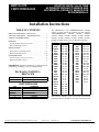
The HH57AC078 and CRENTDIF004A00 enthalpy
sensors are used with the Economi$er IV (part numbers
CRECOMZR008C00, 020A02, 021A03, 024A02,
025A02, 038A00, 039A00, 040A00, 041A00, 042A00,
046A00, 047A00, 050A00, 051A00, 056A00, 057A00,
062A00, 064A00) and are used on the following units:
UNIT
48HE
50HE
50HEQ
48HJ
50HJ
50HJQ
48PD
50PD
48PG
50PG
48PM
50PM
48TC
50TC
48TF
50TFF
50TCQ
48HC
50HC
50HCQ
50TFQ
48TJ
SIZE
003---006
003---006
003---006
004---028
004---028
004---016
05---06
05---06
03---28
03---28
20---28
20---28
04---16
04---16
004---014
004---014
04--- 14
04--- 14
04--- 14
04--- 12
UNIT
542J
548F
549B
549C
551A
551B
551C
558F
558J
559F
579F
580F
580J
581A
581B
581C
548J
581J
551J
549J
SIZE
150, 180
036---120
036---120
024---060
155---300
036---150
024---060
036---300
04---16
180---300
180---300
036---300
04---16
155---300
036---150
024---060
04---14
04---14
04---14
04---12
004---012
016--- 028
50TJ
016--- 028
48TM
004--- 028
50TM
004--- 028
The accessory enthalpy sensor can be used on all rooftop
units with a factory-- installed or accessory Economi$er IV.
Edition Date: 3/11
Manufacturer reserves the right to change, at any time, specifications and designs without notice and without obligations.
Catalog No:IIK---HH57CRENT ---03
Replaces: IIK--- HH57CRENT--- 02
Table 1 – Economi$er IV Sensor Usage
Outdoor Air Dry Bulb
Economi$er IV WITH OUTDOOR AIR DRY BULB SENSOR
Accessories Required
None. The outdoor air dry bulb sensor is
factory installed.
Differential Dry Bulb
CRTEMPSN002A00*
APPLICATION
Single Enthalpy
HH57AC078
Differential Enthalpy
HH57AC078 and CRENTDIF004A00*
CO2 for DCV Control using a Wall ---Mounted
CO2 Sensor
33ZCSENCO2 or CGCDXSEN004A00{
CO2 for DCV Control using a Duct ---Mounted
CO2 Sensor
33ZCSENCO2 or
CGCDXSEN004A00{
and 33ZCASPCO2 or
CGCDXASP001A00**
OR
CRCBDIOX005A00{{
* CRENTDIF004A00 and CRTEMPSN002A00 accessories are used on many different base units. As such, these kits may contain parts
that will not be needed for installation.
{ 33ZCSENCO2 and CGCDXSEN004A00 are accessory CO2 sensors.
** 33ZCASPCO2 and CGCDXASP001A00 are accessory aspirator boxes required for duct--- mounted applications.
{{ CRCBDIOX005A00 is an accessory that contains both 33ZCSENCO2 and 33ZCASPCO2 accessories.
NOTE: Some 48/50PD05--- 06,PG03--- 28,PM20--- 28, 48/50TC04--- 16, 50TCQ04--- 14, 48/50HC04--- 14, 50HCQ04--- 12, 558J/580J04--- 16,
548J04--- 14, 581/551J04--- 14, and 549J04--- 12 units may have factory--- installed enthalpy sensor.
SAFETY CONSIDERATIONS
GENERAL
Installation and servicing of air-- conditioning equipment
can be hazardous due to system pressure and electrical
components. Only trained and qualified service personnel
should install, repair, or service air-- conditioning
equipment.
Untrained personnel can perform the basic maintenance
functions. All other operations should be performed by
trained service personnel. When working on
air-- conditioning equipment, observe precautions in the
literature, tags and labels attached to the unit, and other
safety precautions that may apply.
Follow all safety codes. Wear safety glasses and work
gloves. Use quenching cloth for unbrazing operations.
Have fire extinguishers available for all brazing
operations.
Recognize safety information. This is the safety-- alert
. When you see this symbol on the unit and in
symbol
instructions or manuals, be alert to the potential for
personal injury.
Understand the signal words DANGER, WARNING, and
CAUTION. These words are used with the safety-- alert
symbol. DANGER identifies the most serious hazards
which will result in severe personal injury or death.
WARNING signifies a hazard which could result in
personal injury or death. CAUTION is used to identify
unsafe practices which may result in minor personal
injury or product and property damage. NOTE is used to
highlight suggestions which will result in enhanced
installation, reliability, or operation.
The 48/50PD, PG, PM. TC, TCQ, HC, HCQ, 558J, 580J,
548J, 581J, 551J and 549J units have a choice of dry-- bulb
or enthalpy sensor with the factory-- installed Economi$er
IV. All other units come with the dry-- bulb sensor as
standard with the factory-- installed Economi$er IV.
For units equipped with dry-- bulb enthalpy sensors,
accessory HH57AC078 can be used to reconfigure the
Economi$er IV for outdoor enthalpy changeover control.
Accessories HH57AC078 and CRENTDIF004A00 can
both be added for differential enthalpy control and the
sensor is used for outdoor temperature control. (See
Table 1.)
!
WARNING
Outdoor Enthalpy Changeover Control
For enthalpy control, accessory enthalpy sensor (part
number HH57AC078) is required. When the outdoor air
enthalpy rises above the outdoor enthalpy changeover set
point, the outdoor-- air damper moves to its minimum
position.
Differential Enthalpy Control
For differential enthalpy control, the Economi$er IV
controller uses two enthalpy sensors (HH57AC078 and
CRENTDIF004A00), one in the outside air and one in the
return airstream. The Economi$er IV controller compares
the outdoor air enthalpy to the return air enthalpy to
determine Economi$er IV use. The controller selects the
lower enthalpy air (return or outdoor) for cooling. For
example, when the outdoor air has a lower enthalpy than
the return air and is below the set point, the Economi$er
IV opens to bring in outdoor air for free cooling.
ELECTRICAL SHOCK HAZARD
Failure to follow this warning could result in personal
injury and/or death.
Disconnect power supply and install lockout tag before attempting to install accessory.
2
INSTALLATION
NOTE: The 48/50PD, PG, PM, TC, TCQ, HC, HCQ,
558J, 580J, 548J, 581J, 551J and 549J units have a choice
of dry-- bulb or enthalpy sensor with the factory-- installed
Economi$er IV.
GROMMET
LOCATION
OUTDOOR AIR
TEMPERATURE
SENSOR
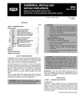
Single Outdoor Air Enthalpy Sensor
Installation for 48/50PG03--16 and
48/50PD05--06 Units
RETURN
AIR TEMPERATURE
SENSOR
(HIDDEN)
If installing the enthalpy sensor on an accessory
Economi$er IV, it is easier to install the enthalpy sensor
before installing the Economi$er IV. If installing the
sensor on a factory-- installed Economi$er IV, it is easier to
install the enthalpy sensor before installing the
Economi$er IV hoods.
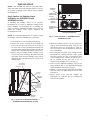
Facing Economizer
C101047
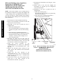
NOTE: For horizontal applications, it is easiest to install
the enthalpy sensor before making duct connections.
Fig. 2 - Sensor Locations — 48/50PD05-- 06 and
48/50PG03-- 16 Units
1. Turn off power to unit and install Lockout Tag.
2. Remove the screws securing the Economi$er IV
hood to the unit. Save the screws for use in Step 7.
On units with a factory-- installed Economi$er IV,
the panel will be hinged and should not be removed
from the unit. Open the hinged panel and secure it.
3. Remove the pre-- existing outdoor enthalpy sensor
and save the screws for Step 4. Disconnect the pink
and yellow wires from the enthalpy sensor and let
them hang. The wires will be used to connect to the
enthalpy sensor.
4. Mount the enthalpy sensor to the top (outdoor air
side) of the Economi$er IV frame, using the two
sheet metal screws (no. 8) from Step 3. There are
two screw holes in the Economi$er IV frame for
ease of installation.
5. Locate the pink and yellow wires coming from the
Economi$er IV controller terminals “SO+” (pink)
and “SO” (yellow). (See Fig. 4.) Connect the wires
to the enthalpy sensor. Connect the yellow wire to
the “S” terminal and the pink wire to the “+”
terminal on the enthalpy sensor. (See Fig. 5.)
6. If the accessory differential enthalpy sensor is also
being installed, skip to the Differential Enthalpy
Sensor installation instructions on page 7.
7. Replace (or close if hinged panel) the Economi$er
IV panel. Secure the panel using the screws saved
from Step 2.
8. Restore power to the unit and configure the
Economi$er IV controller per the Configuration
section in this manual.
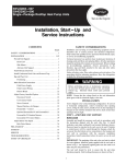
ECONOMI$ER
WIRING PLUGS
ACTUATOR
OUTDOOR
AIR HOOD
OUTDOOR AIR
ENTHALPY
SENSOR
RETURN AIR
ENTHALPY
SENSOR
BAROMETRIC
RELIEF HOOD
ECONOMI$ER
ASSEMBLY
Fig. 1 - Side View of Vertical Economi$er —
48/50PD05-- 06 and 48/50PG03-- 16 Units
C07407
3
HH57AC078, CRENTDIF004A00
ACCESSORY
POWER
EXHAUST
Single Outdoor Air Enthalpy Sensor
Installation for 48/50PG20--28,
48/50PM20--28, 48/50HJ020--028 and
551A/581A210--300 Units
N
2V
P
Min
Pos
T1
24
Vac
HOT
24 Vac
COM
DCV
Max
10V
2V
2V
SO
SR
1
2
5
DCV
Set
10V
SO+
SR+
_
DCV
AQ
DAMPER MOTOR
ACCESS PANEL
+
Open
T
AQ1
HH57AC078, CRENTDIF004A00
TR1
Set
10V
EXH
P1
1. Turn off power to unit and install Lockout Tag.
2. Remove the damper motor access panel at the back of
the unit. (See Fig. 3.) Save screws for use in Step 7.
TR
EXH
N1
Free
Cool
B
C
A
D
3
4
EF
EF1
C06038
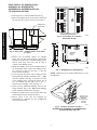
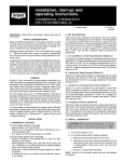
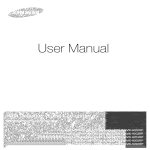
Fig. 4 - Economi$er IV Controller
(Honeywell W7212)
5/16 (8)
C08478
Fig. 3 - Back View — Damper Motor Access Panel
Location
3. Remove the pre-- existing outdoor air enthalpy
sensor and save the screws for Step 4. Disconnect
the pink and yellow wires from the enthalpy sensor
and let them hang. The wires will be used to
connect to the enthalpy sensor.
4. Mount the enthalpy sensor in the predrilled holes on
the Economi$er frame (where the enthalpy sensor
was removed in Step 3). (See Fig. 6.) Use the
screws removed in Step 3.
5. Locate the pink and yellow wires coming from the
Economi$er IV controller terminals “SO+ ” (pink)
and “SO” (yellow). (See Fig. 4.) Connect the wires
to the enthalpy sensor. Connect the yellow wire to
the “S” terminal and the pink wire to the “+”
terminal on the enthalpy sensor. (See Fig. 5.)
6. If the accessory differential enthalpy sensor is also
being installed, skip to the Differential Enthalpy
Sensor installation instructions on page 8.
7. Replace the damper motor access panel. Secure the
panel using the screws saved from Step 2.
8. Restore power to the unit and configure the
Economi$er IV controller per the Configuration
section in this manual.
3-5/32
(80)
2-3/4
(70)
9/16
(14)
7/32 (6)
HH57AC078
Enthalpy
Sensor
S
3-7/8 (96)
1 (25)
C07409
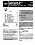
Fig. 5 - Enthalpy Sensor Specifications
NOTE: Dimensions are in inches. Dimensions in ( ) are
in millimeters.
ACTUATOR
OUTDOOR AIR
TEMPERATURE
SENSOR
AND ENTHALPY
SENSOR
LOCATION
C07410
Fig. 6 - Outdoor Air Sensor Location —
48/50PG20-- 28, 48/50PM20-- 28, 48/50HJ020-- 028,
and 551A/581A210-- 300 Units
4
ECONOMI$ER IV
CONTROLLER
WIRING
HARNESS
ACTUATOR
(HIDDEN)
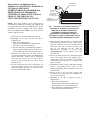
LOW TEMPERATURE
COMPRESSOR
LOCKOUT SWITCH
OUTSIDE AIR
TEMPERATURE SENSOR
(OPERATING LOCATION)
NOTE: This section assumes you are starting with an
Economi$er IV installed in the rooftop and equipped with
a dry bulb temperature sensor (p/n HH57AC074). If your
Economi$er is already equipped with single enthalpy
sensor (p/n HH57AC078), STOP. You do not need to
continue with this section.
C07367
Fig. 7 - Economi$er IV Component Locations —
48/50TC04-- 16, 48/50HC04-- 14, 50TCQ04-- 14,
50HCQ04-- 14, 48/50HE,TF,TM004-- 014,
48/50HJ004-- 014, 50HEQ,TFQ003-- 012,
50HJQ004-- 012, 558J/580J04-- 16, 548J04-- 14,
581/551J04-- 14, 549J04-- 12, 548F/549B,C036-- 120,
551B/558B/558J/580F/580J/581B036-- 150 Units
1. Turn off power to unit and install Lockout Tag.
2. Depending on the type of panels the unit is
equipped with:
a. Units with standard panels —
Remove the Economi$er hood from the base
unit and save the screws for Step 9a.
b. For units with factory-- installed hinged panels —
Open the hinged panel and secure it. Since the
panel is hinged, do not remove it from the unit.
3. Disconnect the black and red wires from the
pre-- existing temperature sensor (p/n HH57AC074)
and let them hang. Remove the air temperature
sensor and save screws (no. 8) for use in Step 4.
The wires will be used later to connect to the
enthalpy sensor.
4. Use the 2 sheet metal screws (no. 8) from Step 3 to
mount the enthalpy sensor on the front left of the
Economi$er frame. (See Fig. 7.) Use the 2 screw
holes in the Economi$er frame.
5. Ensure the black and red wires are connected on the
Economi$er IV controller correctly. The red wire
should be connected to the “SO” terminal and the
black wire to the “SO+” terminal. (See Fig. 4.) If
they are not connected this way, make the
connections as described.
If you are using
CRENTDIF004A00, the kit contains an extra red
and black wire.
6. Pick up the black and red wires left hanging from
Step 3 and connect them to the enthalpy sensor.
Connect the red wire to the sensor’s “S” terminal
and the black wire to the sensor’s “+” terminal. See
Fig. 5 for details.
7. If installation of the accessory differential enthalpy
sensor is also planned, skip to Step 3 of the
Differential Enthalpy Sensor installation section of
this instruction.
8. Restore power to the unit and configure the
Economi$er IV controller per the Configuration
section of this manual.
9. Depending on the type of panels the unit is
equipped with:
a. Units with standard panels —
Re-- install the Economi$er hood. Secure the
panel using the screws saved from Step 1a.
b. Units with factory-- installed hinged panels —
Close the hinged panel and latch it.
5
HH57AC078, CRENTDIF004A00
Single Outdoor Air Enthalpy Sensor
Installation for 48/50TC04--16, 48/50HC04--14,
50TCQ04--14, 50HCQ04--12
48/50HE,TF,TM003--014, 48/50HJ004--014,
50HEQ,TFQ003--012, 50HJQ004--012,
558J/580J04--16, 548J04--14, 581/551J04--14,
549J04--12, 548F/549B,C036--120,
551B,C/558F/580F/581B,C024--151 Units
Single Outdoor Air Enthalpy Sensor
Installation for 48/50HJ015--017,
50HJQ014--016, 48/50TJ,TM016--028,
542J150--180, 551A/581A155--180,
558F/559F/579F/580F180--300 Units
ECONOMI$ER IV
HH57AC078, CRENTDIF004A00
NOTE: This section assumes you are starting with an
Economi$er IV installed in the rooftop and equipped with
a dry bulb temperature sensor (p/n HH57AC074). If your
Economi$er is already equipped with a single enthalpy
sensor (p/n HH57AC078), STOP. You do not need to
continue with this section.
FRAME
TOP
OUTDOOR AIR
TEMPERATURE SENSOR
(INSTALLED OPERATION
POSITION)
LOW TEMPERATURE
COMPRESSOR
LOCKOUT SWITCH
C07412
Fig. 8 - Economi$er IV Component Locations —
48/50HJ015-- 017, 50HJQ014-- 016, 48/50TJ,
TM016-- 028, 542J150-- 180, 551A/581A155-- 180,
558F/559F/579F/580F180-- 300 Units
1. Turn off power to unit and install Lockout Tag.
2. Remove the Economi$er hood from the base unit
and save the screws for Step 9.
3. Depending on the type of panels the unit is
equipped with:
a. Units with standard panels —
Access the Economi$er by removing the
return–air filter access panel. Save the screws
for Step 11a.
b. For units with factory-- installed hinged panels —
Access the Economi$er IV controller by opening
the hinged return-- air filter access panel and
securing it. Since the panel is hinged, do not
remove it from the unit.
4. Disconnect the black and red wires from the
pre-- existing temperature sensor (p/n HH57AC074)
and let them hang. Remove the air temperature
sensor and save the screws (no. 8) for use in Step 5.
The wires will be used later to connect to the
enthalpy sensor.
5. Mount the enthalpy sensor to the front right of the
Economi$er frame, as shown in Fig. 8. Use the two
sheet metal screws (no. 8) from Step 4 and screw
into the holes in the Economi$er frame.
6. Ensure the black and red wires are connected on the
Economi$er IV controller correctly. The red wire
should be connected to the “SO” terminal and the
black wire to the “SO+” terminal. If they are not
connected this way, make the connections as
described. If you are using CRENTDIF004A00, the
kit contains an extra red and black wire.
7. Pick up the the black and red wires left hanging
from Step 4 and connect them to the enthalpy
sensor. Connect the red wire to the sensor’s “S”
terminal and the black wire to the sensor’s “+”
terminal. See Fig. 5 for details.
8. If installation of the accessory differential enthalpy
sensor is also planned, skip to Step 3 of the
Differential Enthalpy Sensor installation section of
this instruction.
9. Re-- install the Economi$er hood using the screws
from Step 2.
10. Restore power to the unit and configure the
Economi$er IV controller per the Configuration
section of this manual.
11. Depending on the type of panels the unit is
equipped with:
a. Units with standard panels —
Re-- install the return-- air filter access panel using
the screws from Step 3a.
b. For units with factory-- installed hinged panels —
Close the hinged panel and latch it.
6
4. If there is a pre-- existing differential enthalpy
sensor, remove the sensor. To remove the sensor,
disconnect the blue and orange wires from the
differential enthalpy sensor and let them hang. They
are used later to connect the differential enthalpy
sensor. Remove the differential enthalpy sensor and
save the screws for use in Step 5.
5. Locate screw holes in the Economi$er deck
partition. Mount the differential enthalpy sensor
onto the backside of the deck, directly behind the
outdoor air enthalpy sensor (already installed) as
shown in Fig. 1 and 2. Use the screws provided.
6. Remove the 620-- ohm resistor that connects “SR+”
and “SR” on the Economi$er IV controller.
7. Route the control wires from the Economi$er IV
controller to the differential enthalpy sensor.
Connect the blue and orange wires to the
Economi$er control board terminals labeled “SR+”
(blue) and “SR” (orange). (See Fig. 4.) Route the
wires through the grommet installed in Step 3. The
grommet seals this hole air-- tight while allowing the
wires to pass through.
8. Connect the blue and orange wires to the
differential enthalpy sensor. Connect the blue wire
to the “+” terminal and the orange wire to the “S”
terminal on the enthalpy sensor. (See Fig. 5.)
9. Reinstall the Economi$er hood and inlet screens, if
removed in Step 2.
10. Restore power to the unit and configure the
Economi$er IV controller per the Configuration
section in this manual.
If installing the differential enthalpy sensor on an
accessory Economi$er, it is easier to install the differential
enthalpy sensor before installing the Economi$er. If
installing the sensor on a factory-- installed Economi$er, it
is easier to install the differential enthalpy sensor before
installing the Economi$er hoods.
A single enthalpy sensor (HH57AC078) must be installed
in addition to the differential enthalpy sensor
(CRENTDIF004A00) to achieve differential enthalpy
Economi$er control.
For horizontal applications, it is easiest to install the
differential enthalpy sensor before making duct
connections.
Differential Enthalpy Sensor Installation
Instructions for 48/50PD05--06 and
48/50PG03--16 Units
NOTE: All wiring for the sensors on 48/50PG and
48/50PM units is factory-- provided. The red and black
wires provided with the accessory are not used.
1. Turn off power to unit and install Lockout Tag.
2. Remove the Economi$er hood from the base unit
and save the screws for use in Step 9. On units with
factory-- installed Economi$ers, the panel is hinged
and should not be removed from the unit. Open the
hinged panel and secure it.
3. Remove the plug button in the Economi$er deck
and install the grommet supplied with the kit into
the hole. (See Fig. 2.)
7
HH57AC078, CRENTDIF004A00
Differential Enthalpy Sensor
Differential Enthalpy Sensor Installation for
48/50PG20--28, 48/50PM20--28,
48/50HJ020--028, and 551A/581A210--300
Units
4. If there is a pre-- existing differential temperature
sensor, remove the sensor. To remove the sensor,
disconnect the blue and orange wires from the
differential temperature sensor and let them hang.
They are used later to connect the differential
enthalpy sensor.
5. Locate holes on the back (return air) side of the
Economi$er IV frame and mount the differential
enthalpy sensor on the frame. Use the screws
provided.
6. Remove the 620-- ohm resistor that connects “SR+”
and “SR” on the Economi$er IV controller.
7. Route the control wires from the Economi$er IV
controller to the differential enthalpy sensor.
Connect the blue and orange wires to the
Economi$er IV control board terminals labeled
“SR+” (blue) and “SR” (orange). (See Fig. 4.)
Route the wires through the grommet installed in
Step 3. The grommet seals this hole air-- tight while
allowing the wires to pass through.
8. Connect the blue and orange wires to the
differential enthalpy sensor. Connect the blue wire
to the “+” terminal and the orange wire to the “S”
terminal on the enthalpy sensor. (See Fig. 6.)
9. Replace the damper motor access panel. Secure
panel with the screws saved from Step 2.
10. Restore power to the unit and configure the
Economi$er IV controller. See the Configuration
section.
HH57AC078, CRENTDIF004A00
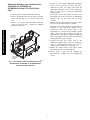
1. Turn off power to unit and install Lockout Tag.
2. Remove the damper motor access panel at the back
of the unit. (See Fig. 3.) Save the screws for later
use.
3. Drill a 7/8 in. hole in the Economi$er block-- off
panel, as shown in Fig. 9. Install the supplied
grommet into the hole.
GROMMET
DRILL HOLE
LOCATION
INSULATED
BLOCK-OFF
PANEL
C07405
Fig. 9 - Economi$er IV Block-- Off Panel Location 48/50PG20-- 28, 48/50PM20-- 28, 48/50HJ020-- 028,
and 551A/581A210-- 300 Units
8
3. Using
the
screws
provided
in
the
CRENTDIF004A00 kit, mount the differential
enthalpy sensor in the return air duct as shown in
Fig. 10.
4. Remove the 620-- ohm resistor that connects “SR+”
and the “SR” terminals on the Economi$er IV
controller.
5. Route the red and black wires (provided in the
CRENTDIF004A00 kit) between the Economi$er
IV controller and the installed location of the differential enthalpy sensor.
6. Connect the red wire to the “S” terminal and the
black wire to the “+” terminal on the sensor. (See
Fig. 5.)
7. Connect the red wire to the “SR” terminal and the
black wire to the “SR+” terminal on the
Economi$er IV controller. (See Fig. 4.)
8. Restore power to the unit and configure the
Economi$er IV controller per the Configuration
section of this manual.
9. Depending on the type of panels the unit is
equipped with:
a. Units with standard panels —
Re-- install the Economi$er hood.
b. Units with factory-- installed hinged panels —
Close the hinged panel and latch it.
NOTE: This section assumes you are starting with an
Economi$er IV installed in the rooftop and equipped with
a single enthalpy sensor (p/n HH57AC078) installed,
regardless of whether the Economi$er came that way or
you have completed the installation of an accessory
sensor. If you do not already have a single enthalpy
sensor installed, first install the single enthalpy sensor as
described earlier in this instruction.
1. Turn off power to unit and install Lockout Tag.
2. Depending on the type of panels the unit is
equipped with:
a. Units with standard panels —
Remove the Economi$er hood from the base
unit and save the screws for Step 9a.
b. Units with factory-- installed hinged panels —
Open the hinged panel and secure it. Since the
panel is hinged, do not remove it from the unit.
ECONOMI$ER IV
CONTROLLER
ECONOMI$ER IV
GROMMET
RETURN AIR
SENSOR
RETURN DUCT
(FIELD-PROVIDED)
C07085
Fig. 10 - Return Air Enthalpy Sensor Mounting Location —
48/50TC04-- 16, 48/50HC04-- 14, 50TCQ04-- 14, 50HCQ04-- 12 48/50HE,TF,TM003-- 014,
48/50HJ004-- 014, 50HEQ,HJQ004-- 012, TFQ004-- 012, 558J/580J04-- 16, 581/551J04-- 14,
548J04-- 14, 549J04-- 12 ,548F/549B036-- 120, 551B,C/558F/580F/581B,C024-- 151 Units
9
HH57AC078, CRENTDIF004A00
Differential Enthalpy Sensor Installation
Instructions for 48/50TC04--16,
48/50HC04--14, 50TCQ04--14, 50HCQ04--12,
48/50HE,TF,TM003--014, 48/50HJ004--014,
50HEQ,HJQ004--012, TFQ004--012,
558J/580J04--16, 548J04--14, 581/551J04--14,
549J04--12, 548F/549B036--120,
551B,C/558F/580F/581B,C024--151 Units
Differential Enthalpy Sensor Installation
Instructions for 48/50HJ015--017,
50HJQ014--016, 48/50TJ,TM016--028,
542J150--180, 551A/581A155--180,
558F/559F/579F/580F180--300 Units
9. Re-- install the Economi$er hood using the screws
from Step 2.
10. Restore power to the unit and configure the
Economi$er IV controller per the Configuration
section of this manual.
11. Depending on the type of panels the unit is
equipped with:
a. Units with standard panels —
Re-- install the return-- air filter access panel using
the screws from Step 3a.
b. Units with factory-- installed hinged panels —
Close the hinged panel and latch it.
HH57AC078, CRENTDIF004A00
NOTE: This section assumes you are starting with an
Economi$er IV installed in the rooftop and equipped with
a single enthalpy sensor (p/n HH57AC078) installed. If
you do not already have a single enthalpy sensor installed,
first install the single enthalpy sensor as described earlier
in this instruction.
1. Turn off power to unit and install Lockout Tag.
2. Remove the Economi$er hood from the base unit
and save the screws for Step 9.
3. Depending on the type of panels the unit is
equipped with:
a. Units with standard panels —
Access the Economi$er by removing the return-air filter access panel. Save the screws for Step
11a.
b. Units with factory-- installed hinged panels —
Access the Economi$er IV controller by opening
the hinged return-- air filter access panels and
securing it. Since the panel is hinged, do not
remove it from the unit.
4. Disconnect the black and red wires from the
pre-- existing temperature sensor and let them hang.
Remove the air temperature sensor. The wires will
be used later to connect to the enthalpy sensor.
5. Using
the
screws
provided
in
the
CRENTDIF004A00 kit, mount the differential
enthalpy sensor to the Economi$er frame. (See
Fig. 10.)
6. Remove the 620-- ohm resistor connected to the
“SR+” and the “SR” terminals on the Economi$er
IV controller.
7. Connect the red wire, provided in the
CRENTDIF004A00 kit, to the “S” terminal and the
black wire, also provided, to the “+” terminal on the
sensor. (See Fig. 5.)
8. Connect the red wire to the “SR” terminal and the
black wire to the “SR+” terminal on the
Economi$er IV controller. (See Fig. 4.)
TR
1
TR
c
Va
24 M
CO
24
c
Va
T
HO
H
EX t
Se
_
+
V
10
N1
2
2V
N
P1
1
H
EX
en
Op
P
T1
T
4
V
DC x
Ma
3
EF
V
10
V
DC t
Se
V
10
V
DC
1
AQ
AQ
1
EF
2V
2V
+
SO
e
Fre ol
Co
SO
+
SR
SR
IAQ
SENSOR
5
Min s
Po
C
B
D
A
RETURN AIR
SENSOR
ECONOMI$ER IV
CONTROLLER
C07406
Fig. 11 - Return Air Enthalpy Sensor Mounting
Location — 48/50HJ015-- 017, 50HJQ014-- 016,
48/50TJ,TM016-- 028,
542J150-- 180, 551A/581A155-- 180,
558F/559F/579F/580F180-- 300 Units
10
CONFIGURATION
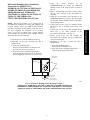
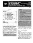
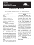
Outdoor Enthalpy Changeover Control
When the outdoor air enthalpy rises above the adjustable
free cooling/enthalpy changeover set point, the
outdoor-- air damper moves to its minimum position. The
free cooling/enthalpy changeover set point is set with the
free cooling/enthalpy changeover set point potentiometer
on the Economi$er IV controller. The set points are A, B,
C, and D. (See Fig. 12 and 13.) The factory-- installed
620-- ohm jumper must be in place across terminals SR
and SR+ on the Economi$er IV controller. (See Fig. 4.)
The Economi$er IV controller compares the outdoor air
enthalpy to the return air enthalpy to determine whether to
select the lower enthalpy air (return or outdoor) for
cooling purposes. For example, when the outdoor air has a
lower enthalpy than the return air and is below the set
point, the Economi$er IV brings in outdoor air for free
cooling.
When using this mode of changeover control, turn the free
cooling/enthalpy changeover set point potentiometer fully
clockwise to the D setting.
C07385
Fig. 12 - Economi$er IV Controller Potentiometer
and LED Locations
46
85
90
95 100 105 110
(29) (32) (35) (38) (41) (43)
44
CONTROL CONTROL POINT
CURVE
APPROX. deg. F (deg. C)
80
(27)
42
AT 50% RH
)
IDI
LA
RE
80
A
40
20
60
(16)
50
22
60
70
24
65
(18)
10
0
90
28
26
EN
UM
EH
TIV
R
PE
U
32
30
70
(21)
TH
AL
PY
BT
75
(24)
34
PO
UN
TY
38
(%
RY
AI
40
R
73 (23)
70 (21)
67 (19)
63 (17)
36 D D
16
18
55
(13) B
14
50
(10)
12
45
(7)
30
A
B
C
D
C
20
D
40
(4)
10
35
(2)
B A
D C
35
(2)
40
(4)
45
(7)
50
(10)
55
60
65
70
75
80
85
90
95 100 105 110
(13) (16) (18) (21) (24) (27) (29) (32) (35) (38) (41) (43)
HIGH LIMIT
CURVE
APPROXIMATE DRY BULB TEMPERATURE--degrees F (degrees C)
C06037
Fig. 13 - Enthalpy Changeover Set Points
11
HH57AC078, CRENTDIF004A00
Differential Enthalpy Control