1
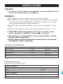
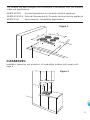
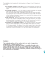
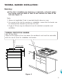
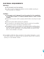
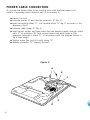
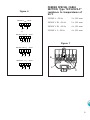
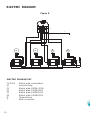
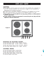
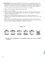
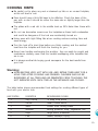
INSTALLATION and SERVICE INSTRUCTIONS
USE and CARE INSTRUCTIONS
DEH60S
DEH60W
ELECTRIC COOKTOPS
distributed by
DèLonghi
Pty Ltd
INSTALLATION
CAUTION:
■
In order to avoid a hazard this appliance must be installed according to these instructions for installation.
WARNING:
■
■
■
■
■
■
■
This appliance is to be installed only by an authorised person.
This appliance must be used only for the task it has explicitly been designed
for, that is for cooking foodstuffs. Any other form of usage is to be considered as inappropriate and therefore dangerous.
Do NOT place combustible materials or products on this appliance at any
time.
Do NOT spray aerosols in the vicinity of this appliance while it is in use.
IMPORTANT NOTE: This appliance shall not be used as a space
heater, especially if installed in marine craft or caravans.
The appliance is not intended for use by young children or infirm
persons without supervision.
Young children should be supervised to ensure they do not play with
the appliance without supervision.
TECHNICAL INFORMATIONS:
Rapid plate
Rapid plate
Normal plate
Normal plate
Voltage
Maximum absorbed power
Ø
Ø
Ø
Ø
145
180
180
145
1500 W
2000 W
1500 W
1000 W
230 - 240 VAC 50 Hz
6.0 - 6.5 kW
DIMENSIONS (Table 2):
(Note: Also refer to Figure 1 side)
General Dimensions
Width
Depth
Depth Below Mounting Surface
Cut-out Dimensions
Width
Depth
2
580 mm
500 mm
30 mm
550 mm
470 mm
This cooktop has been designed and constructed in accordance with the following
codes and specifications:
AS/NZS 60335-1
General Requirements for Domestic electrical appliances
AS/NZS 60335-2-6 Particular Requirements for Domestic electrical cooking appliances
AS/NSZ 1044
Electromagnetic Compatibility Requirements.
Figure 1
580
47
0
65
m
in
.
500
50
min
550
CLEARANCES:
Installation clearances and protection of combustible surfaces shall comply with
page 4.
650 mm
450 mm
Figure 2
3
The installation shall comply with the dimensions in Figures 1 and 2, bearing in
mind that:
■
A minimum clearance of 30 mm has to be kept between the bottom of
the cooking hob and the top of an appliance or a thermal barrier (see next
page).
■
Overhead clearances - In no case shall the clearance between the highest
part of the hob and a range hood be less than 600 mm.
Any other downward facing combustible surface less than 600 mm above
the highest part of the hob shall be protected for the full width and depth
of the cooking surface area. However, in no case shall this clearance to any
surface be less than 450 mm.
■
Side clearances - Where the dimension from the periphery of the nearest
burner to any vertical combustible surface is less than 200 mm, the surface
shall be protected to a height of not less than 150 mm above the hob for
the full dimension (width or depth) of the cooking surface area.
■
Protection of combustible surfaces - The required protection shall ensure
that the surface temperature of the combustible surface does not exceed
50 °C above ambient. The fixing of 5 mm thick ceramic tiles to the surface
or attaching fire resistant material to the surface and covering with sheet
metal with minimum thickness of 0.4 mm would satisfy this requirement.
Caution:
The underside surface of the cooking hob can reach a temperature
exceeding 95 °C during normal use.
If after installation the underside surface is accessible through underbench cupboard doors and the like, it is essential that a rigid barrier is
installed so that such access is restricted. In order to avoid a hazard the
barrier must be of low thermal conductivity material installed according to
the instructions for installation.
4
THERMAL BARRIER INSTALLATION:
Warning:
■
If the hob is installed over drawers or cupboards, a thermal protection barrier must be fitted at least 30 mm beneath the base of the
hob (see Figure 3).
Note:
1. Above not applicable if hob is mounted directly above an oven
2. For access to the hob for servicing or installation, ensure that the barrier can
be removed from beneath by the use of a tool.
3. A gap of 20 mm may be allowed at rear for electrical connection and
ventilation.
THERMAL PROTECTION BARRIER
(min. 15 mm thick)
Fitted the full lenghts of the hob below the workbench and must be removable
with the use of a tool for installation and service.
;;
30 mm
30 mm
;
20 mm gap
Figure 3
5
INSTALLATION
1. Spread out the gasket “C” over the workbench at the edge of the cut out
taking care to overlap the gasket at the corners.
2. Slot in the cooking hob into the cut out of the workbench and locate it
correctly.
3. Adjust the clamps “A” and tighten the screws “B” until the hob is firmly
secured.
4. Using a sharp tool, trim any excess gasket which protrudes from the edge
of the hob. Take care not to damage the countertop.
Figure 4
6
A
40 mm max.
B
20 mm min.
C
ELECTRICAL REQUIREMENTS
Warning:
■
THIS APPLIANCE MUST BE EARTHED.
■
In order to avoid a hazard this appliance must be installed according to
these instructions for installation.
Caution:
■
■
If the supply cord is damaged it must be replaced by the manufacturer or it’s Service Agent or a similarly qualified person in order to avoid
a hazard.
■
Ensure that the power outlet is properly earthed before connecting the appliance.
■
Disconnect power before servicing the appliance.
■
The connection to the electrical network must be carried out by qualified
personnel and must be according to standards in force.
■
The appliance must be connected to the electrical network verifying above
all that the voltage corresponds to the value indicated on the specifications
plate and that the cables section of the electrical plant can bear the load
which is also indicated on the plate.
It is possible to effect the direct connection to the network interposing a omnipolar switch between the appliance and the electrical network with a minimum
opening of 3 mm between contacts.
7
FEEDER CABLE CONNECTION
To connect the feeder cable to the cooking hobs with electrical plates or to
replace, if necessary, some electrical part, it is necessary to:
■
■
■
■
■
■
■
Upturn the hob
Unscrew screws “A” and remove protection “B” (fig. 5)
Insert connecting plates “C” into terminal block “D” (fig. 7) as shown in the
diagram in fig. 6
Unscrew cable clamp “E” (fig. 5)
Insert correct section and type mains flex (see special chapter) through mains
hitch “F” of protection “B,” and connect mains and earth wires to their
respective terminals in block “D,” in accordance with the diagram shown in
fig. 8 (next page).
Tighten mains flex, and fix it with clamp “E.”
Replace protection “B,” keeping flex taut.
Figure 5
A
B
F
E
D
8
FEEDER SPECIAL CABLE
SECTION Type “HO5V2V2-F”
Figure 6
220-240 V
1 2
resistance to temperatures of
90°C
220-240 V ~ 50 Hz
3 x 2,50 mm2
380-416 V 3N ~ 50 Hz
5 x 1,50 mm2
380-416 V 2N ~ 50 Hz
4 x 1,50 mm2
220-240 V 3 ~ 50 Hz
4 x 2,50 mm2
50 Hz
3 4 5
PE
L1
N
(L 2)
380-416 V 3N
1 2
50 Hz
3 4 5
PE
Figure 7
L1 L2 L3
N
380-416 V 2N
1 2
50 Hz
3 4 5
PE
L1
N
1
L2
2
3
4
5
D
220-240 V 3
1 2
50 Hz
3 4 5
C
PE
L1
L2
L3
C
9
ELECTRIC DIAGRAM
Figure 8
M
T
P1
P2
1 2 4 3
1 2 4 3
F1
5
4
7
P1
3
2
1
P3
9
P2
5
4
7
P1
3
2
1
ELECTRIC DIAGRAM KEY
F1/2/3/4
S1
P1
P2
P3
P4
M
T
10
P4
1 2 4 3
F3
F2
P3
9
P2
P3
1 2 4 3
Electric plate commutators
Line pilot lamp
Electric plate 2000W -230V
Electric plate 1500W-230V
Electric plate 1500W-230V
Electric plate 1000W-230V
Terminal block
Earth connection
F4
P3
9
P2
5
4
P3
9
P2
5
4
7
P1
3
2
1
7
P1
3
2
1
S1
USE and CARE
CAUTION:
■
■
■
■
■
This appliance must be used only for the task it has explicitly been designed for,
that is for cooking foodstuffs. Any other form of usage is to be considered as
inappropriate and therefore dangerous.
Do NOT place combustible materials or products on this appliance at any time.
Do NOT spray aerosols in the vicinity of this appliance while it is in use.
The appliance is not intended for use by young children or infirm persons
without supervision.
Young children should be supervised to ensure they do not play with the
appliance without supervision.
2
3
Figure 9
4
1
9 5
6
7
8
POSITION OF ELECTRIC PLATES
1.
2.
3.
4.
Front left electric plate
Rear left electric plate
Rear right electric plate
Front right electric plate
Ø
Ø
Ø
Ø
180
180
145
145
-
Rapid Normal
Normal
Rapid -
2000 W
- 1500 W
- 1000 W
1500 W
CONTROL PANEL
5.
6.
7.
8.
9.
Front left electric plate 1 control knob
Rear left electric plate 2 control knob
Rear right electric plate 3 control knob
Front right electric plate 4 control knob
Electrical plates control lamp
11
■
Important: Before using the hob for the first time, it is necessary to burn off
the appliance to dry off the plates and remove any protective coatings that may
still be on the plates. To do this, boil a saucepan of water on each plate for
about 10 minutes. There may be a strong odour and a light smoke visible during this process. This will cease when the process is complete.
1. Make sure that all the controls are turned to zero.
2. Switch on the electricity.
3. Turn the knob for the ring you require. The element will become hotter as you
select a higher number. A little practice will help you to estimate the setting
required for different purposes.
4. Always use a flat bottomed saucepan which has a base as similar to the
diameter of the hotplate as possible. Ensure that the bottom of the pan you are
using is dry.
5. Never switch the hotplate on without any saucepans on top. This will cause
heat to travel along the spillage tray causing the control panel to heat up and
may also cause subsequent damage to adjacent worktops.
Figure 10
■
12
Never cook food directly on the hotplate: always use a pan or suitable
container.
COOKING HINTS:
■
Be careful not to place any wet or steamed up lids on an unused hotplate,
as this will lead to rust.
■
Pans should have a thick flat base to be effective. Check the base of the
pan with a ruler. It should be either the same size or slightly larger than the
hotplate.
■
The plates with a red dot in the middle heat up 30% faster than those without.
■
Do not use decorative covers over the hotplates as these hold condesation
and could be dangerous if the hob was accidentally turned on.
■
Using pans with tight fitting lids when cooking reduces cooking time and
saves energy.
■
Turn the heat off a short time before you finish cooking and the residual
heat from the hotplate will finish the cooking for you.
■
Never have handles overhanging the worktop - they can easily be caught and
overbalance; similarly, never have the handles overlapping other hotplates that
are in use.
■
It is always worthwhile buying good saucepans for the best results from
your hob.
Warning:
■
HOBS BECOME VERY HOT WITH USE, AND RETAIN THEIR HEAT FOR A
LONG TIME AFTER COOKING HAS FINISHED. CHILDREN SHOULD BE
SUPERVISED AT ALL TIMES AND BE PREVENTED FROM TOUCHING THE
HOT SURFACES UNTIL SUCH TIME AS THE APPLIANCE HAS COOLED.
The table below shows recommended heat settings for cooking different types of
food with your electric hob:
HEAT POSITION
DESCRIPTION
RECOMMENDED COOKING
1
Very Gentle
To keep food warm
2
Gentle
Stews, cream sauce
3
Slow
Frozen food, boiling water
4
Medium
Boiling potatoes, soup, vegetables, fish
5
High
Large stews, omelettes
6
Fast
Steaks, escalops, frying
13
■
Please note that these are only guidelines, you will quickly learn from experience which setting is correct for your needs.
ECONOMIC COOKING
■ The electric plate retains heat, so you may find that you can switch off the
heat 5 minutes before you finish cooking.
■
To reduce the cooking time, the plate can be set to the maximum setting at
the beginning. It can then be reduced later.
CLEANING AND MAINTENANCE
■
Before you begin cleaning you must ensure that the hob is switched off.
■
Do not use a steam cleaner because the moisture can get into the
appliance thus make it unsafe.
■
Deposits of fat on the electric hotplates can be removed by turning on the
hob for a few seconds. The fat will dry out, and can be brushed off when
the plate is cool. If staining remains, special cleaners for electric plates can
be purchased to return the plate to it’s original colour
■
Electric hotplates are made of cast iron and though durable, will rust if moisture is left on them regularly. Do not place wet lids from other pans onto an
unused hotplate. From time to time, apply a thin coat of special hob cleaner.
Enamelled parts - mod. DEH60W
■
■
All the enamelled parts must be washed only with a sponge with soapy
water or other non-abrasive products.
Dry carefully.
Stainless steel hob - mod. DEH60S
■
■
14
Clean with special products which are available on the market.
Dry preferably with a microfibre or soft cloth.
TROUBLESHOOTING:
If you acquire a problem with your hob, check the following points before calling an
engineer.
1. The power is switched on.
2. The controls are switched on.
3. Both the fuse and the mains fuse are intact.
Servicing the appliance:
Service may be obtained from your local Authorised Service Centre.
Descriptions and illustrations in this booklet are given as simply indicative. The manufacturer reserves the right,
considering the characteristics of the models described here, at any time and without notice, to make eventual
necessary modifications for their construction or for commercial needs.
15
cod. 1103193 - ß1