1
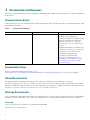
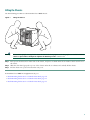
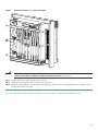
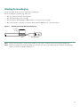
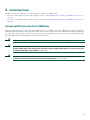
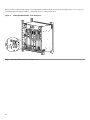
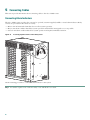
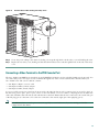
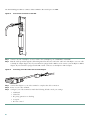
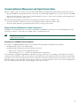
Quick Start Guide
Cisco 10008 Router
1
Documentation and Resources
2
Preparing for Installation
3
Installing the Router
4
Connecting Power
5
Connecting Cables
6
Powering On the System
7
Configuring the Cisco 10008 Router at Startup
8
Formatting Flash Disks and Flash Cards
9
Managing the File Systems
10 Troubleshooting Installation Problems
1 Documentation and Resources
This section contains information to help you prepare for installing the Cisco 10008 router. It contains a list of online documentation
and resources.
Document Version History
This is the first version of the document with an online part number. The document version history beginning with this online
part number is in Table 1.
Table 1
Document Version History
Document Version
Date
Change Summary
OL-7815-01
July, 2005
This version contains basic hardware
installation and configuration
information. Regulatory compliance and
safety information is now in the new
Regulatory Compliance and Safety
Information for the Cisco 10000 Series
Routers.
Installation information for all line cards
is in the Cisco 10000 Series Routers Line
Card Hardware Installation Guide.
Site planning and preparation
information, previously in the
Technology of Edge Aggregation
document, is now in the Cisco 10000
Series Router Performance Routing
Engine Installation.
Documentation Survey
Is Cisco documentation helpful? Click here or go to
http://forums.cisco.com/eforum/servlet/viewsflash?cmd=showform&pollid=rtgdoc01!rtgdoc to give us your feedback.
Related Documentation
For detailed hardware installation instructions, refer to the Cisco 1000 Series Router Hardware documents.
For other documentation, see the Cisco 10000 Series Routers Documentation Roadmap, which provides links to all software,
hardware, troubleshooting documentation, and other information. For regulatory compliance and safety information, see the
Regulatory Compliance and Safety Information for the Cisco 10000 Series Routers.
Obtaining Documentation
Cisco documentation and additional literature are available on Cisco.com. Cisco also provides several ways to obtain technical
assistance and other technical resources. These sections explain how to obtain technical information from Cisco Systems.
Cisco.com
You can access the most current Cisco documentation at this URL:
http://www.cisco.com/techsupport
2
You can access the Cisco website at this URL:
http://www.cisco.com
You can access international Cisco websites at this URL:
http://www.cisco.com/public/countries_languages.shtml
Product Documentation DVD
Cisco documentation and additional literature are available in the Product Documentation DVD package, which may have
shipped with your product. The Product Documentation DVD is updated regularly and may be more current than printed
documentation.
The Product Documentation DVD is a comprehensive library of technical product documentation on portable media. The DVD
enables you to access multiple versions of hardware and software installation, configuration, and command guides for Cisco
products and to view technical documentation in HTML. With the DVD, you have access to the same documentation that is
found on the Cisco website without being connected to the Internet. Certain products also have .pdf versions of the
documentation available.
The Product Documentation DVD is available as a single unit or as a subscription. Registered Cisco.com users (Cisco direct
customers) can order a Product Documentation DVD (product number DOC-DOCDVD=) from the Ordering tool or Cisco
Marketplace.
Cisco Ordering tool:
http://www.cisco.com/en/US/partner/ordering/
Cisco Marketplace:
http://www.cisco.com/go/marketplace/
Ordering Documentation
Beginning June 30, 2005, registered Cisco.com users may order Cisco documentation at the Product Documentation Store in
the Cisco Marketplace at this URL:
http://www.cisco.com/go/marketplace/
Cisco will continue to support documentation orders using the Ordering tool:
• Registered Cisco.com users (Cisco direct customers) can order documentation from the Ordering tool:
http://www.cisco.com/en/US/partner/ordering/
• Instructions for ordering documentation using the Ordering tool are at this URL:
http://www.cisco.com/univercd/cc/td/doc/es_inpck/pdi.htm
• Nonregistered Cisco.com users can order documentation through a local account representative by calling Cisco Systems
Corporate Headquarters (California, USA) at 408 526-7208 or, elsewhere in North America, by calling 1 800 553-NETS
(6387).
Documentation Feedback
You can rate and provide feedback about Cisco technical documents by completing the online feedback form that appears with
the technical documents on Cisco.com.
You can send comments about Cisco documentation to [email protected].
You can submit comments by using the response card (if present) behind the front cover of your document or by writing to the
following address:
Cisco Systems
Attn: Customer Document Ordering
170 West Tasman Drive
San Jose, CA 95134-9883
We appreciate your comments.
3
Cisco Product Security Overview
Cisco provides a free online Security Vulnerability Policy portal at this URL:
http://www.cisco.com/en/US/products/products_security_vulnerability_policy.html
From this site, you can perform these tasks:
• Report security vulnerabilities in Cisco products.
• Obtain assistance with security incidents that involve Cisco products.
• Register to receive security information from Cisco.
A current list of security advisories and notices for Cisco products is available at this URL:
http://www.cisco.com/go/psirt
If you prefer to see advisories and notices as they are updated in real time, you can access a Product Security Incident Response
Team Really Simple Syndication (PSIRT RSS) feed from this URL:
http://www.cisco.com/en/US/products/products_psirt_rss_feed.html
Reporting Security Problems in Cisco Products
Cisco is committed to delivering secure products. We test our products internally before we release them, and we strive to correct
all vulnerabilities quickly. If you think that you might have identified a vulnerability in a Cisco product, contact PSIRT:
• Emergencies — [email protected]
An emergency is either a condition in which a system is under active attack or a condition for which a severe and urgent
security vulnerability should be reported. All other conditions are considered nonemergencies.
• Nonemergencies — [email protected]
In an emergency, you can also reach PSIRT by telephone:
• 1 877 228-7302
• 1 408 525-6532
Tip
We encourage you to use Pretty Good Privacy (PGP) or a compatible product to encrypt any sensitive information that
you send to Cisco. PSIRT can work from encrypted information that is compatible with PGP versions 2.x through 8.x.
Never use a revoked or an expired encryption key. The correct public key to use in your correspondence with PSIRT is
the one linked in the Contact Summary section of the Security Vulnerability Policy page at this URL:
http://www.cisco.com/en/US/products/products_security_vulnerability_policy.html
The link on this page has the current PGP key ID in use.
Obtaining Technical Assistance
Cisco Technical Support provides 24-hour-a-day award-winning technical assistance. The Cisco Technical Support &
Documentation website on Cisco.com features extensive online support resources. In addition, if you have a valid Cisco service
contract, Cisco Technical Assistance Center (TAC) engineers provide telephone support. If you do not have a valid Cisco service
contract, contact your reseller.
4
Cisco Technical Support & Documentation Website
The Cisco Technical Support & Documentation website provides online documents and tools for troubleshooting and resolving
technical issues with Cisco products and technologies. The website is available 24 hours a day, at this URL:
http://www.cisco.com/techsupport
Access to all tools on the Cisco Technical Support & Documentation website requires a Cisco.com user ID and password. If you
have a valid service contract but do not have a user ID or password, you can register at this URL:
http://tools.cisco.com/RPF/register/register.do
Note
Use the Cisco Product Identification (CPI) tool to locate your product serial number before submitting a web or phone
request for service. You can access the CPI tool from the Cisco Technical Support & Documentation website by clicking
the Tools & Resources link under Documentation & Tools. Choose Cisco Product Identification Tool from the
Alphabetical Index drop-down list, or click the Cisco Product Identification Tool link under Alerts & RMAs. The CPI
tool offers three search options: by product ID or model name; by tree view; or for certain products, by copying and
pasting show command output. Search results show an illustration of your product with the serial number label location
highlighted. Locate the serial number label on your product and record the information before placing a service call.
Submitting a Service Request
Using the online TAC Service Request Tool is the fastest way to open S3 and S4 service requests. (S3 and S4 service requests are
those in which your network is minimally impaired or for which you require product information.) After you describe your
situation, the TAC Service Request Tool provides recommended solutions. If your issue is not resolved using the recommended
resources, your service request is assigned to a Cisco engineer. The TAC Service Request Tool is located at this URL:
http://www.cisco.com/techsupport/servicerequest
For S1 or S2 service requests or if you do not have Internet access, contact the Cisco TAC by telephone. (S1 or S2 service requests
are those in which your production network is down or severely degraded.) Cisco engineers are assigned immediately to S1 and
S2 service requests to help keep your business operations running smoothly.
To open a service request by telephone, use one of the following numbers:
Asia-Pacific: +61 2 8446 7411 (Australia: 1 800 805 227)
EMEA: +32 2 704 55 55
USA: 1 800 553-2447
For a complete list of Cisco TAC contacts, go to this URL:
http://www.cisco.com/techsupport/contacts
Definitions of Service Request Severity
To ensure that all service requests are reported in a standard format, Cisco has established severity definitions.
Severity 1 (S1)—Your network is “down,” or there is a critical impact to your business operations. You and Cisco will commit
all necessary resources around the clock to resolve the situation.
Severity 2 (S2)—Operation of an existing network is severely degraded, or significant aspects of your business operation are
negatively affected by inadequate performance of Cisco products. You and Cisco will commit full-time resources during normal
business hours to resolve the situation.
Severity 3 (S3)—Operational performance of your network is impaired, but most business operations remain functional. You
and Cisco will commit resources during normal business hours to restore service to satisfactory levels.
Severity 4 (S4)—You require information or assistance with Cisco product capabilities, installation, or configuration. There is
little or no effect on your business operations.
5
Obtaining Additional Publications and Information
Information about Cisco products, technologies, and network solutions is available from various online and printed sources.
• Cisco Marketplace provides a variety of Cisco books, reference guides, documentation, and logo merchandise. Visit Cisco
Marketplace, the company store, at this URL:
http://www.cisco.com/go/marketplace/
• Cisco Press publishes a wide range of general networking, training and certification titles. Both new and experienced users
will benefit from these publications. For current Cisco Press titles and other information, go to Cisco Press at this URL:
http://www.ciscopress.com
• Packet magazine is the Cisco Systems technical user magazine for maximizing Internet and networking investments. Each
quarter, Packet delivers coverage of the latest industry trends, technology breakthroughs, and Cisco products and solutions,
as well as network deployment and troubleshooting tips, configuration examples, customer case studies, certification and
training information, and links to scores of in-depth online resources. You can access Packet magazine at this URL:
http://www.cisco.com/packet
• iQ Magazine is the quarterly publication from Cisco Systems designed to help growing companies learn how they can use
technology to increase revenue, streamline their business, and expand services. The publication identifies the challenges
facing these companies and the technologies to help solve them, using real-world case studies and business strategies to help
readers make sound technology investment decisions. You can access iQ Magazine at this URL:
http://www.cisco.com/go/iqmagazine
or view the digital edition at this URL:
http://ciscoiq.texterity.com/ciscoiq/sample/
• Internet Protocol Journal is a quarterly journal published by Cisco Systems for engineering professionals involved in
designing, developing, and operating public and private internets and intranets. You can access the Internet Protocol Journal
at this URL:
http://www.cisco.com/ipj
• Networking products offered by Cisco Systems, as well as customer support services, can be obtained at this URL:
http://www.cisco.com/en/US/products/index.html
• Networking Professionals Connection is an interactive website for networking professionals to share questions, suggestions,
and information about networking products and technologies with Cisco experts and other networking professionals. Join
a discussion at this URL:
http://www.cisco.com/discuss/networking
• World-class networking training is available from Cisco. You can view current offerings at this URL:
http://www.cisco.com/en/US/learning/index.html
6
2 Preparing for Installation
This section guides you through the process of preparing for your router installation.
Warning
Only trained and qualified personnel should be allowed to install or replace this equipment. Statement 49
Site Preparation
Before you install the Cisco 10008 router, consider:
• The power and cabling requirements that must be in place at your installation site
• The equipment required to install the router
• The environmental conditions your installation site must meet to maintain normal operation
Do not unpack the system until you are ready to install it. Keep the chassis in the shipping container to prevent accidental
damage until you determine an installation site. Use the appropriate unpacking documentation included with the system.
Recommended Tools and Supplies
Table 2 lists the tools, equipment, and supplies necessary to install the Cisco 10008 chassis in the rack and connect the system
ground to the chassis.
Table 2
Tools and Supplies
Quantity
Description
Comments
1
Number 2 Phillips screwdriver
—
1
3/16-inch flat-blade screwdriver
—
1
1/4-inch flat-blade screwdriver
—
1
Antistatic mat or antistatic foam
—
1
Electrostatic discharge (ESD) grounding strap or the disposable ESD
strap shipped with the system
—
1
Wire-stripping tool
—
1
Crimping tool
Must fit diameter of grounding lugs.
2
2-hole grounding lugs
Must fit No. 6 stranded, No. 6 weld, or
37/24 flex cables. Each lug has two holes,
centered 0.625 in. (1.587 cm) apart and
accepts M5 screws.
Varies
Grounding wire
6 AWG, 0.204 in. (5.18 mm) recommended.
2
M5 power entry module (PEM) screws with captive, locking washers Included in accessory kit shipped with
Cisco 10008 router.
Varies
Screws to attach ground wire to grounding point at site
Part requirements depend on location.
7
3 Installing the Router
The Cisco 10008 router can be rack-mounted in a 19-inch rack with either a flush-mount or center-mount configuration, or in
a 23-inch rack in a center-mount configuration. Use the rack-mounting kit provided with your system.
If you choose to install the Cisco 10008 router on a workbench or tabletop:
Step 1
Ensure that you have a minimum of 3 inches (7.62 cm) of clearance at the inlet and exhaust vents (at both the front
and top/rear sides of the chassis) and a minimum of 19 inches (48.3 cm) of clearance at the front and rear of the chassis
for cables and maintenance.
Step 2
Follow the lifting instructions provided for lifting the chassis in the “Lifting the Chassis” section on page 9.
Step 3
Attach the cable-management bracket. See Figure 8 on page 16.
8
Lifting the Chassis
Use the following procedure to rack-mount the Cisco 10008 chassis:
Figure 1
Lifting the Chassis
FANS
FAN
OK
FAILURE
MULTIFAN
FAILURE
When hot CAUTION
removal swapping
this fan
be done and replaceme
tray,
system in under two nt must
shutdown
minutes
will occur. or
1
2
CISCO
10000
3
4
CISCO
10000
0A
PROC
CISCO
10000
ESSOR
CISCO
10000
FAIL
FAIL
FAIL
FAIL
CISCO
10000
0B
ONLY
5
CISCO
10000
6
CISCO
10000
7
CISCO
10000
FAIL
NS
OLE
8
CISCO
10000
FAIL
FAIL
CISCO
10000
CO
OLE
P
LOO
RM
ALA
RIER
CAR
P
LOO
RM
ALA
RIER
CAR
FAIL
CO
NS
0
AUX
AUX
0
ACT
ER
0
NE
K
0
T
P
LOO
RM
ALA
RIER
LIN
CAR
T
P
LOO
RM
ALA
RIER
NE
K
CAR
LIN
IVIT
ETH
Y
1
T
SLO
0
T
SLO
1
ACT
ER
P
LOO
RM
ALA
RIER
1
T
SLO
0
T
SLO
1
CAR
IVIT
ETH
Y
0
2
1
2
1
POWER
1
FAULT
MISWIR
E
3
2
2
P
RM
LOO
RIER
RX
ALA
TX
CAR
LINK
2
3
4
3
4
3
3
CAR
5
4
5
RX
4
TX
RIER
4
5
5
5
AL
MA
JO
MIN
R
OR
AL
JO
MIN
R
OR
6XCT3–DS0
STA
TU
FAI S
L
ESSOR
ONLY
30007
PROC
ITIC
MA
6XCT3–DS0
STA
TU
FAI S
L
O
6XCT3–DS0
FAULT
MISWIR
E
AC
CR
OC–12/STM–4 POS SM–IR
6XCT3–DS0
6XCT3–DS0
ITIC
PERFORMANCE ROUTING ENGINE
O
PERFORMANCE ROUTING ENGINE
CH OC-12-DSO SM-IR
GIGABIT ETHERNET
POWER
AC
CR
Warning
At least three people are required to mount the chassis in the equipment rack: two people are needed to hold the
chassis in place while a third person tightens the mounting screws. Statement 234
Step 1
Each person should stand on either side of the chassis, and place one hand under the air intake at the bottom front of
the chassis.
Step 2
With the other hand, grasp the top rear of the chassis under the air exhaust and carefully lift the chassis.
Step 3
Lift the chassis into position between the rack posts.
To install the Cisco 10008 in an equipment rack, go to:
• Rack-Mounting the Router in a 19-Inch 4-Post Rack, page 10
• Rack-Mounting the Router in a 19-Inch 2-Post Rack, page 11
• Rack-Mounting the Router in a 23-Inch 2-Post Rack, page 13
9
Rack-Mounting the Router in a 19-Inch 4-Post Rack
Use the following procedure to rack-mount the Cisco 10008 chassis in a 19-inch 4-post rack:
Figure 2
Attaching the Chassis to a 19-Inch 4-Post Rack
FANS
OK
FAN
FAILURE
MULTIFAN
FAILURE
When hot CAUTION
removal swapping
this fan
be done and replacem
tray,
system in under two ent must
shutdown
minu
will occutes or
r.
1
2
CISCO
10000
3
FA
CISCO
10000
4
0A
PROC
ESSO
0B
R ONLY
FA
IL
CISCO
10000
CISCO
10000
IL
FA
IL
FA
IL
CISCO
10000
5
CISCO
10000
6
CISCO
10000
IL
FA
OP
M
AR
R
IE
AU
X
0
CA
CA
0
OP
M
AR
R
IE
LO
AL
RR
0
OP
M
AR
R
IE
LO
AL
RR
OP
M
AR
R
IE
LO
AL
RR
1
OT
SL
0
OT
SL
1
AC
TIV
IT
E
Y
TH
E
R
LI
N
N
E
K
T
CA
AC
TIV
IT
E
Y
TH
E
R
LI
N
N
E
K
T
1
OT
SL
0
OT
SL
1
0
2
1
2
POWER
FAULT
MISWIR
E
CISCO
10000
IL
FA
C
O
N
S
O
LE
AU
X
LO
AL
RR
CA
OP
M
AR
R
IE
LO
AL
RR
CA
0
8
CISCO
10000
IL
FA
IL
FA
C
O
N
S
O
LE
7
CISCO
10000
1
1
3
2
IE
M
OP
R
AR
2
LO
RX
AL
TX
RR
NK
CA
LI
2
3
4
3
4
3
3
CA
5
RR
4
5
RX
R
4
TX
IE
4
5
5
5
AC
O
6XCT3–DS0
OC–12/STM–4 POS SM–IR
6XCT3–DS0
6XCT3–DS0
S
TA
TU
S
FA
IL
C
R
IT
IC
A
M
L
A
JO
R
M
IN
O
R
PERFORMANCE ROUTING ENGINE
C
R
IT
IC
A
M
L
A
JO
R
M
IN
O
R
PERFORMANCE ROUTING ENGINE
6XCT3–DS0
6XCT3–DS0
CH OC-12-DSO SM-IR
GIGABIT ETHERNET
POWER
FAULT
MISWIR
E
AC
O
S
TA
TU
S
FA
IL
PROC
ESSO
30010
R ONLY
Warning
At least three people are required to mount the chassis in the equipment rack: two people are needed to hold the
chassis in place while a third person tightens the mounting screws. Statement 234
Step 1
Align the mounting bracket holes with the rack post holes. (The third person attaches the chassis to the rack.)
Step 2
Insert the six mounting screws through the mounting bracket into the rack, and tighten the screws.
Go to the “Attaching the Cable-Management Bracket” section on page 16 to continue the installation process.
10
Rack-Mounting the Router in a 19-Inch 2-Post Rack
Use the following procedure to rack-mount the Cisco 10008 chassis in a 19-inch 2-post rack:
Figure 3
Attaching the Mounting Brackets to the Chassis
FANS
OK
FAN
FAILURE
MULTIFAN
FAILURE
When hot CAUTION
removal swapping
this fan
be done and replacem
tray,
system in under two ent must
shutdown
minu
will occutes or
r.
1
2
CISCO
10000
3
4
CISCO
10000
FA
IL
FA
CISCO
10000
0A
PROC
ESSO
FA
IL
CISCO
10000
0B
R ONLY
FA
IL
CISCO
10000
5
IL
CISCO
10000
6
CISCO
10000
FA
IL
FA
IL
CA
AU
X
OP
M
AR
R
IE
LO
AL
RR
OP
M
AR
R
IE
LO
AL
RR
AU
X
CISCO
10000
FA
IL
C
O
N
S
O
LE
CA
0
8
CISCO
10000
FA
IL
C
O
N
S
O
LE
7
CISCO
10000
0
CA
CA
CA
0
OP
M
AR
R
IE
LO
AL
RR
0
OP
M
AR
R
IE
LO
AL
RR
OP
M
AR
R
IE
LO
AL
RR
1
OT
0
OT
1
AC
TIV
IT
E
Y
TH
E
R
LI
N
N
E
K
T
SL
1
SL
1
OT
0
OT
SL
SL
AC
TIV
IT
E
Y
TH
E
R
LI
N
N
E
K
T
0
2
1
2
1
POWER
1
FAULT
MISWIR
E
3
2
CA
IE
M
OP
R
AR
2
LO
RX
AL
TX
RR
NK
LI
2
3
4
3
4
3
3
CA
5
RR
4
5
RX
R
4
TX
IE
4
5
5
5
6XCT3–DS0
OC–12/STM–4 POS SM–IR
30012
S
TA
TU
S
FA
IL
PROC
ESSOR
ONLY
Warning
6XCT3–DS0
S
TA
TU
S
FA
IL
C
R
IT
IC
A
M
L
A
JO
R
M
IN
O
R
6XCT3–DS0
FAULT
MISWIR
E
AC
O
PERFORMANCE ROUTING ENGINE
C
R
IT
IC
A
M
L
A
JO
R
M
IN
O
R
PERFORMANCE ROUTING ENGINE
6XCT3–DS0
6XCT3–DS0
CH OC-12-DSO SM-IR
GIGABIT ETHERNET
POWER
AC
O
At least three people are required to mount the chassis in the equipment rack: two people are needed to hold the
chassis in place while a third person tightens the mounting screws. Statement 234
Step 1
Attach the two mounting brackets to the chassis so the flanges are positioned at the center of the chassis.
Step 2
Insert the ten mounting screws through the mounting bracket into the router, and tighten the screws.
11
Figure 4
Attaching the Chassis to a 19-Inch 2-Post Rack
FANS
OK
FAN
FAILURE
MULTIFAN
FAILURE
When hot CAUTION
removal swapping
this fan
be done and replacem
tray,
system in under two ent must
shutdown
minu
will occutes or
r.
1
2
CISCO
10000
3
FA
CISCO
10000
4
0A
PROC
ESSO
0B
R ONLY
FA
IL
CISCO
10000
CISCO
10000
IL
FA
IL
FA
IL
CISCO
10000
5
CISCO
10000
6
CISCO
10000
IL
FA
AU
X
0
0
OP
LO
M
AR
AL R
IE
RR
CA
IT
E
Y
TH
E
R
LI
N
N
E
K
T
OP
LO
M
AR
AL R
IE
RR
CA
1
AC
TIV
1
OT
SL
0
OT
SL
1
OT
SL
0
OT
SL
IT
E
Y
TH
E
R
LI
N
N
E
K
T
OP
LO
M
AR
AL R
IE
RR
CA
AC
TIV
1
0
0
2
1
2
1
1
POWER
3
2
IE
M
OP
R
AR
2
LO
RX
AL
TX
RR
NK
2
3
CA
LI
FAULT
MISWIR
E
CISCO
10000
IL
FA
C
O
N
S
O
LE
AU
X
OP
LO
M
AR
AL R
IE
RR
CA
OP
LO
M
AR
AL R
IE
RR
CA
0
8
CISCO
10000
IL
FA
IL
FA
C
O
N
S
O
LE
7
CISCO
10000
4
3
4
3
3
4
5
4
RX
4
TX
R
IE
RR
CA
5
5
5
5
R
IT
A
L
JO
R
IN
O
R
O
C
R
IT
IC
A
M
L
A
JO
R
M
IN
O
TA
TU
S
FA
6XCT3–DS0
S
6XCT3–DS0
R
6XCT3–DS0
FAULT
MISWIR
E
AC
OC–12/STM–4 POS SM–IR
6XCT3–DS0
IC
A
M
PERFORMANCE ROUTING ENGINE
C
M
PERFORMANCE ROUTING ENGINE
O
6XCT3–DS0
CH OC-12-DSO SM-IR
GIGABIT ETHERNET
POWER
AC
S
TA
TU
IL
S
FA
PROC
ESSO
R ONLY
Warning
30013
IL
At least three people are required to mount the chassis in the equipment rack: two people are needed to hold the
chassis in place while a third person tightens the mounting screws. Statement 234
Step 3
Lift the chassis into position between the rack posts.
Step 4
Align the mounting bracket holes with the rack post holes.
Step 5
Insert the eight mounting screws through the mounting bracket into the rack, and tighten the screws. The third person
attaches the chassis to the rack.
Go to the “Attaching the Cable-Management Bracket” section on page 16 to continue the installation process.
12
Rack-Mounting the Router in a 23-Inch 2-Post Rack
Use the following procedure to rack-mount the Cisco 10008 chassis in a 23-inch 2-Post rack:
Figure 5
Attaching Mounting Brackets to the Chassis
FANS
OK
FAN
FAILURE MULTIFAN
FAILURE
When hot CAUTION
removal swapping
this fan
be done and replaceme
tray,
system in under two nt must
shutdown
minu
will occutes or
r.
1
2
CISCO
10000
3
FA
CISCO
10000
4
0A
PROC
ESSO
0B
R ONLY
CISCO
10000
CISCO
10000
IL
FA
IL
FA
IL
FA
IL
CISCO
10000
5
CISCO
10000
6
CISCO
10000
CISCO
10000
IL
FA
IL
FA
C
O
N
S
O
LE
AU
X
OP
LO
M
AR
AL R
IE
RR
CA
OP
LO
M
AR
AL R
IE
RR
CA
0
8
CISCO
10000
IL
FA
IL
FA
C
O
N
S
O
LE
7
CISCO
10000
AU
X
0
OP
LO
M
0
AR
AL R
IE
RR
CA
OP
LO
M
AR
AL R
IE
RR
CA
OP
LO
M
AR
AL R
IE
RR
CA
A
C
TIV
IT
E
Y
TH
E
R
LI
N
N
E
K
T
1
OT
SL
0
OT
SL
1
1
OT
SL
0
OT
SL
1
A
C
TIV
IT
E
Y
TH
E
R
LI
N
N
E
K
T
0
0
2
1
2
1
POWER
1
FAULT
MISWIR
E
3
2
2
OP
LO
RX
TX
NK
M
AR
AL
R
IE
RR
CA
LI
2
3
4
3
4
3
3
4
5
4
RX
4
TX
R
IE
RR
CA
5
5
5
5
R
IT
A
L
A
JO
R
M
IN
O
R
O
C
R
IT
IC
A
M
L
A
JO
R
M
IN
O
TA
TU
S
FA
6XCT3–DS0
S
6XCT3–DS0
R
6XCT3–DS0
FAULT
MISWIR
E
A
C
OC–12/STM–4 POS SM–IR
6XCT3–DS0
IC
M
PERFORMANCE ROUTING ENGINE
C
PERFORMANCE ROUTING ENGINE
O
6XCT3–DS0
CH OC-12-DSO SM-IR
GIGABIT ETHERNET
POWER
A
C
S
TA
TU
IL
S
FA
PROC
ESSO
R ONLY
Step 1
30012
IL
Attach the two mounting brackets to the chassis so the flanges are positioned at the center of the chassis.
13
Figure 6
Attaching 23-Inch 2-Post Rack Bracket Adapters
FANS
OK
FAN
FAILURE
MULTIFAN
FAILURE
When hot CAUTION
removal swapping
this fan
be done and replacem
tray,
system in under two ent must
shutdown
minu
will occutes or
r.
1
2
CISCO
10000
3
FA
CISCO
10000
4
0A
PROC
ESSO
0B
R ONLY
CISCO
10000
CISCO
10000
IL
FA
IL
FA
IL
FA
IL
CISCO
10000
5
CISCO
10000
6
CISCO
10000
IL
FA
CA
AU
X
OP
M
AR
R
IE
LO
AL
RR
OP
M
AR
R
IE
LO
AL
RR
AU
X
0
CA
CA
0
OP
M
AR
R
IE
LO
AL
RR
0
OP
M
AR
R
IE
LO
AL
RR
OP
M
AR
R
IE
LO
AL
RR
1
OT
SL
0
OT
SL
1
AC
TIV
IT
E
Y
TH
E
R
LI
N
N
E
K
T
CA
AC
TIV
IT
E
Y
TH
E
R
LI
N
N
E
K
T
1
OT
SL
0
OT
SL
1
0
2
1
2
1
POWER
1
3
2
2
3
2
OP
LO
RX
TX
M
AR
AL
R
IE
RR
CA
NK
LI
FAULT
MISWIR
E
CISCO
10000
IL
FA
C
O
N
S
O
LE
CA
0
8
CISCO
10000
IL
FA
IL
FA
C
O
N
S
O
LE
7
CISCO
10000
4
3
4
3
3
CA
5
RR
4
5
RX
R
4
TX
IE
4
5
5
5
IT
IC
L
R
O
R
TA
TU
FA
6XCT3–DS0
S
FA
A
JO
IN
OC–12/STM–4 POS SM–IR
TA
TU
S
IL
M
S
IL
PROC
ESSO
R ONLY
Step 2
14
Attach the optional 23-inch adapters to the mounting brackets.
30014
M
A
6XCT3–DS0
S
O
C
R
6XCT3–DS0
FAULT
MISWIR
E
AC
PERFORMANCE ROUTING ENGINE
C
R
IT
IC
A
M
L
A
JO
R
M
IN
O
R
PERFORMANCE ROUTING ENGINE
6XCT3–DS0
6XCT3–DS0
CH OC-12-DSO SM-IR
GIGABIT ETHERNET
POWER
AC
O
Figure 7
Attaching the Chassis to a 23-Inch 2-Post Rack
FANS
OK
FAN
FAILURE
MULTIFAN
FAILURE
When hot CAUTION
removal swapping
this fan
be done and replacem
tray,
system in under two ent must
shutdown
minu
will occutes or
r.
1
2
CISCO
10000
3
FA
CISCO
10000
4
FA
IL
CISCO
10000
0A
PROC
ESSO
0B
R ONLY
CISCO
10000
IL
FA
IL
FA
IL
CISCO
10000
5
CISCO
10000
6
CISCO
10000
N
S
O
O
CA
CA
OP
M
AR
R
IE
LO
AL
RR
OP
M
AR
R
IE
LO
AL
RR
N
S
O
LE
OP
M
AR
R
IE
LO
0
T
AL
0
RR
E
CA
Y
N
OP
R
M
AR
R
IE
E
K
LO
N
AL
TH
LI
RR
E
T
OP
E
IT
M
AR
R
IE
N
X
TIV
CA
AC
Y
LO
K
IT
R
AL
N
E
1
OT
SL
0
OT
SL
1
TH
RR
1
OT
SL
0
OT
SL
1
TIV
CA
E
LI
IL
FA
C
LE
X
AU
AC
CISCO
10000
IL
FA
O
AU
0
8
CISCO
10000
IL
FA
IL
FA
C
0
7
CISCO
10000
0
2
1
2
1
POWER
1
FAULT
MISWIR
E
3
2
CA
IE
M
OP
R
AR
2
LO
RX
AL
TX
RR
NK
LI
2
3
4
3
4
3
3
CA
5
RR
4
5
RX
R
4
TX
IE
4
5
5
5
6XCT3–DS0
OC–12/STM–4 POS SM–IR
Warning
6XCT3–DS0
S
TA
TU
S
FA
IL
R ONLY
30015
PROC
ESSO
C
R
IT
IC
A
M
L
A
JO
R
M
IN
O
R
6XCT3–DS0
S
TA
TU
S
FA
IL
AC
O
PERFORMANCE ROUTING ENGINE
6XCT3–DS0
C
R
IT
IC
A
M
L
A
JO
R
M
IN
O
R
FAULT
MISWIR
E
PERFORMANCE ROUTING ENGINE
AC
O
6XCT3–DS0
CH OC-12-DSO SM-IR
GIGABIT ETHERNET
POWER
At least three people are required to mount the chassis in the equipment rack: two people are needed to hold the
chassis in place while a third person tightens the mounting screws. Statement 234
Step 3
Lift the chassis into position between the rack posts.
Step 4
Align the mounting bracket holes with the rack post holes.
Step 5
Insert the eight mounting screws through the mounting bracket into the rack, and tighten the screws. The third person
attaches the chassis to the rack.
Go to the “Attaching the Cable-Management Bracket” section on page 16 to continue the installation process.
15
Attaching the Cable-Management Bracket
Use the following procedure to attach the cable-management bracket to the Cisco 10008 chassis:
Figure 8
Attaching the Cable-Management Bracket
FANS
OK
FAN
FAILURE
MULTIFAN
FAILURE
When hot CAUTION
removal swapping
this fan
be done and replaceme
tray,
system in under two nt must
shutdown
minut
will occures or
.
1
2
CISCO
10000
3
4
CISCO
10000
0A
PROC
ESSO
CISCO
10000
0B
R ONLY
CISCO
10000
IL
FA
IL
FA
IL
FA
IL
FA
CISCO
10000
5
CISCO
10000
6
CISCO
10000
SO
N
AU
SO
LE
AU
X
0
AC
AC
0
OP
LO
M
OP
LO
M
AR
AL R
IE
RR
CA
AR
AL R
IE
RR
CA
OP
LO
M
TI
V
ETH ITY
ER
LI
N
N
ET
K
LI
1
OT
SL
0
OT
SL
1
AR
AL R
IE
RR
CA
TI
V
ETH ITY
ER
N
N
ET
K
1
OT
SL
0
OT
SL
1
0
0
2
1
2
POWER
FAULT
MISWIRE
8
CISCO
10000
X
OP
LO
M
OP
LO
M
AR
AL R
IE
RR
CA
AR
AL R
IE
RR
CA
0
O
IL
FA
C
LE
CISCO
10000
IL
FA
N
IL
FA
O
7
CISCO
10000
IL
FA
C
1
1
3
2
2
LO
RX
TX
OP
M
AR
AL
R
IE
RR
CA
NK
LI
2
3
4
3
4
3
3
4
5
4
RX
4
TX
R
IE
RR
CA
5
5
5
5
O
R
M
IT
IC
AJO
AL
R
IN
O
R
O
R
M
IT
IC
AJO
AL
R
IN
O
R
6XCT3–DS0
6XCT3–DS0
STA
TU
S
FA
IL
R ONLY
76221
PROC
ESSO
C
M
6XCT3–DS0
STA
TU
S
FA
IL
AC
OC–12/STM–4 POS SM–IR
6XCT3–DS0
M
PERFORMANCE ROUTING ENGINE
C
PERFORMANCE ROUTING ENGINE
AC
6XCT3–DS0
CH OC-12-DSO SM-IR
GIGABIT ETHERNET
POWER
FAULT
MISWIRE
Step 6
Attach the cable-management bracket to the bottom of the chassis.
Note
The cable-management bracket consists of two pieces (the cable guide and the channel), and is shipped assembled. If
you want to use the cable guide only, you can remove the channel by loosening the captive screws before attaching the
cable guide to the chassis.
Go to the “Attaching the Grounding Lug” section on page 17 to continue the installation process.
16
Attaching the Grounding Lug
Use the procedure in this section to attach the grounding lug:
Before attaching the grounding lug, make sure:
• The ejector levers are in the closed position.
• The chassis mounting screws are tight.
• The Performance Routing Engine (PRE) and line card captive screws are tight.
• The power switches on the DC or AC Power Entry Module (PEM) are set to the Off position.
Figure 9
Attaching Grounding Wire to Grounding Lug
30020
0.75 in.
(2 cm)
Wire
Grounding lug
Step 1
Using a wire-stripping tool, strip about 3/4 inch (2 cm) of the covering from each end of the grounding wire.
Step 2
Insert each stripped end of the grounding wire into the open end of a grounding lug and crimp the grounding lug
securely to the wire using the crimping tool.
17
Connecting the Grounding Lug to the Chassis
132825
Figure 10
1
1
Threaded grounding holes (2)
Warning
Never defeat the ground conductor or operate the equipment in the absence of a suitably installed ground
conductor. Contact the appropriate electrical inspection authority or an electrician if you are uncertain that
suitable grounding is available. Statement 93
Step 3
Attach the grounding lug firmly to threaded holes at the bottom rear of the chassis using two M5 screws.
Step 4
Attach the grounding lug at the other end of the wire to an appropriate grounding point at your site.
Installing Line Cards
Install any line cards before you connect power. See the Cisco 10000 Series Routers Line Card Hardware Installation Guide for
complete installation instructions.
18
4 Connecting Power
Use this section for information about connecting power to the Cisco 10008 router.
• If you are connecting DC power to the system, go to the “Connecting DC Power to the Cisco 10008 Router” section on
page 19.
• If you are connecting AC power to the system, go to the “Connecting AC Power to the Cisco 10008 Router” section on
page 23
Connecting DC Power to the Cisco 10008 Router
This section describes how to connect the Cisco 10008 router to a –48 VDC power source. The power connectors are pillar
terminals on the backplane. For full power redundancy, each set of DC power connectors (terminal blocks labeled A and B) must
be connected to separate power sources. If you do not require power redundancy, you can use only one set of terminals—either
the A terminal block or the B terminal block. Do not use one of each.
Warning
Only trained and qualified personnel should be allowed to install or replace this equipment. Statement 49
Warning
Before working on equipment that is connected to power lines, remove jewelry (including rings, necklaces, and
watches). Metal objects will heat up when connected to power and ground and the heat can cause serious burns
or weld the metal object to the terminals. Statement 43
Warning
This product requires short-circuit (overcurrent) protection, to be provided as part of the building installation.
Install only in accordance with national and local wiring regulations. Statement 1045
19
Be sure you have connected the chassis to an earth ground as instructed in the “Attaching the Grounding Lug” section on page 17,
and then use the following procedure to connect the chassis to a DC power source:
Figure 11
Setting DC PEM Switches to the Off Position
FANS
OK
FAN
FAILUR
E
MULTIFAN
FAILUR
E
When hot CAUTION
removal swapping
this fan
be done and replacement
tray,
must
system in under two
shutdo
wn will minutes or
occur.
1
2
CISCO
10000
3
CISCO
10000
4
0A
PROCES
SOR ONL0B
Y
C100
CISC00
O
10000
6CT3
FA
IL
FA
CISCO
10000
FA
IL
FA
IL
CISCO
10000
5
IL
CISCO
10000
6
C100
CISC00
O
10000
6CT3
FAIL
7
FA
C100
CISC00
O
10000
6CT3
OP
LO
M
AR
AL
IER
RR
CA
0
E
FAIL
X
AU
X
M
0 CA ALARLOOP
PORT0
AC
TI
TY
AC
RN
VI
ET
ET
TY
HE
LI
RN
ET
M
0 CA ALARLOOP
PORT0
M
0 CA ALARLOOP
PORT0
M
0 CA ALARLOOP
PORT0
VI
NK
TI
LI
AC
TY
VI
NK
TI
LI
AC
NK
OP
LO
M
AR
AL
IER
RR
CA
NK
OP
LO
M
AR
AL
IER
RR
CA
TI
HE
LI
1
PORT1
OP
LO
M
AR
AL
IER
RR
CA
VI
ET
1
TY
2
1
PORT1
ALARMS
PORT2
2
1
PORT1
1
PORT1
ALARMS
C
POWER
FAULT
MISWIRE
FAIL
OL
IL
OP
LO
M
AR
AL
IER
RR
CA
NS
FA
FAIL
CO
E
IL
OL
CISCO
10000
FA
IL
NS
AU
8
C100
CISC00
O
10000
6CT3
FA
IL
CO
R
IT
R
PORT2
2
PORT2
2
IN
R
M
R
O
O
IN
AJ
AL
M
IC
M
R
M
OP
IER
AR
LO
RX
AL
TX
RR
O
O
R
AC
4
PORT2
2
IT
O
CA
K
LIN
PORT3
3
C
AJ
AL
M
IC
3
PORT3
3
AC
PORT3
3
O
PORT4
4
PORT3
3
PORT4
4
PORT5
5
PORT4
4
RX
PORT4
4
TX
IER
RR
CA
5
PORT5
5
PORT5
5
PORT5
5
SL
OT
SL
0
OT
S
U
AT IL
ST FA
0
S
U
AT IL
ST FA
BI
TS
BI
TS
6XCT3–DS0
OC–12/STM–4 POS SM–IR
6XCT3–DS0
6XCT3–DS0
P/N ESR-PRE3
P/N ESR-PRE3
PERFORMANCE ROUTING ENGINE
6XCT3–DS0
PERFORMANCE ROUTING ENGINE
POWER
FAULT
MISWIRE
6XCT3–DS0
FAULT
MISWIR
E
CH OC-12-DSO SM-IR
GIGABIT ETHERNET
POWER
PROCES
30019
SOR ONL
Y
Step 1
20
Set the DC PEM switches to the Off position.
Removing the Safety Cover
30023
Figure 12
Step 2
Loosen the captive screw on the rear safety cover and tilt the cover back to lift it up and out from the chassis.
Figure 13
Stripping Insulation
14747
10 mm max
Step 3
Using a wire-stripping tool, strip not more than 0.4 inches (10 mm) of insulation off the ends of the DC power leads.
21
Figure 14
DC Power Connections
RTN (+
)
– 48/–
60
V
DC terminal
block A
DC terminal
block B
30024
RTN (+
)
– 48/–
60
V
Step 4
Connect the DC power lead from the first external power source to the DC terminal block A labeled –48V.
Step 5
Connect the return wire (RTN) to terminal block A labeled RTN (+).
• If you have redundant DC power, continue with Step 6.
• If you do not have redundant DC power, go to Step 8.
Step 6
Connect the DC power lead from the second external power source to the DC terminal block B labeled –48V.
Step 7
Connect the return wire (RTN) to terminal block B labeled RTN (+).
22
Securing DC Power Cables to the Chassis
30025
Figure 15
Step 8
Secure the power cabling to the chassis by feeding a tie wrap through the slot on the safety cover and binding the cables.
Step 9
Replace the rear safety cover, making sure that the power wires exit through the holes on the side of the safety cover.
This completes the installation of the Cisco 10008 chassis in the rack. Go to the “Connecting Cables” section on page 26.
Connecting AC Power to the Cisco 10008 Router
The Cisco 10008 router can be powered on directly from the facility VAC input through the AC PEM (100–240 VAC). The AC
PEM is provided with an IEC 320 250V, 20A power cord with a male-type connector (16A rating for Europe) for the attachment
of power cords used throughout the world.
Warning
Only trained and qualified personnel should be allowed to install or replace this equipment. Statement 49
Caution
The 20A connector on the AC PEM is incompatible with the 15A power strips that are used in most equipment
racks. Wiring codes prevent the AC-input power cable from being used with the power strips in equipment racks.
Note
The AC power cord that connects the PEM to the building VAC is not shipped with the Cisco 10008 and must be
ordered separately.
23
Be sure you have connected the chassis to an earth ground as instructed in the “Attaching the Grounding Lug” section on page 17,
and then use the following procedure to connect AC power to the PEM:
Figure 16
Setting AC PEM Switches to the Off Position
FANS
OK
FAN
FAILUR
E
MULTI
FAN
FAILUR
E
When hot CAUTION
removal swapping
this fan
be done and replacement
tray,
must
system in under two
shutdo
wn will minutes or
occur.
1
2
CISCO
10000
3
CISCO
10000
4
FA
CISCO
10000
0A
PROCES
SOR ON 0B
LY
IL
FA
IL
FA
IL
FA
IL
C100
CISC00
O
10000
6CT3
CISCO
10000
5
CISCO
10000
6
C100
CISC00
O
10000
6CT3
FAIL
IL
FA
CISCO
10000
IL
FA
FAIL
CA
OP
LO
M
AR
AL
IER
RR
FAIL
OP
M
AR
IER
LO
AL
RR
AU
X
M
0 CA ALARLOOP
PORT0
CA
OP
AC
M
0 CA ALARLOOP
PORT0
TI
NK
LI
TY
VI
NK
TI
LI
AC
M
AR
IER
LO
OP
AL
M
AR
IER
LO
M
0 CA ALARLOOP
PORT0
RR
CA
AL
M
0 CA ALARLOOP
PORT0
RR
VI
TY
ET
HE
RN
NK
ET
LI
CA
AC
TI
OP
LO
M
AR
AL
IER
RR
AC
TI
VI
TY
ET
HE
RN
LI
NK
ET
1
1
PORT1
IL
FA
CA
0
8
C100
CISC00
O
10000
6CT3
FAIL
CO
NS
O
LE
AU
X
7
C100
CISC00
O
10000
6CT3
IL
FA
CO
NS
O
LE
VI
TY
2
1
PORT1
ALARMS
PORT2
2
1
PORT1
1
PORT1
ALARMS
C
POWER
FAULT
R
IT
R
PORT2
2
PORT2
2
IN
R
M
R
O
O
IN
AJ
AL
M
IC
M
R
O
O
R
AC
4
PORT2
2
IT
O
OP
LO
RX
K
TX
M
AR
AL
IER
RR
CA
LIN
PORT3
3
C
AJ
AL
M
IC
3
PORT3
3
AC
PORT3
3
O
PORT4
4
PORT3
3
CA
5
RR
PORT4
4
PORT5
5
RX
PORT4
4
TX
IER
PORT4
4
PORT5
5
PORT5
5
PORT5
5
SL
OT
SL
0
BI
S
0
U
AT IL
OT
ST FA
S
U
AT IL
ST FA
POWER
FAULT
TS
BI
TS
6XCT3–DS0
OC–12/STM–4 POS SM–IR
6XCT3–DS0
6XCT3–DS0
P/N ESR-PRE3
P/N ESR-PRE3
PERFORMANCE ROUTING ENGINE
6XCT3–DS0
PERFORMANCE ROUTING ENGINE
6XCT3–DS0
CH OC-12-DSO SM-IR
GIGABIT ETHERNET
POWER
FAULT
30026
PROCES
SOR ON
LY
Step 1
Set the AC PEM switches to the Off position.
Step 2
Connect the power cord from the PEM to the power cord that connects to the facility VAC input.
24
Figure 17
AC Power Cord Connectors in Strain-Relief Devices
1
FANS
OK
FAN
FAILUR
E
MULTI
FAN
FAILUR
E
When hot CAUTION
removal swapping
this fan
be done and replacement
tray,
must
system in under two
shutdo
wn will minutes or
occur.
1
2
CISCO
10000
3
CISCO
10000
4
FA
IL
FA
CISCO
10000
0A
PROCES
FA
IL
CISCO
10000
SOR ON 0B
LY
FA
IL
CISCO
10000
5
IL
CISCO
10000
6
CISCO
10000
7
FA
CISCO
10000
IL
FA
CO
LE
CISCO
10000
FA
IL
NS
O
8
CISCO
10000
FA
IL
CO
OP
LO
M
AR
AL
IER
0
LE
X
RR
OP
LO
M
AR
IER
CA
AL
RR
O
IL
CA
NS
AU
AU
X
0
AC
TI
TY
OP
LO
M
AR
IER
OP
AL
RR
M
AR
IER
LO
0
CA
AL
RR
ET
CA
1
OT
0
OT
SL
SL
RN
NK
OP
TY
HE
LI
M
AR
IER
VI
ET
ET
LO
TI
RN
NK
AL
OT
1
OT
SL
0
SL
LI
RR
AC
HE
1
CA
VI
ET
1
0
0
2
1
2
1
POWER
1
FAULT
3
2
CA
M
OP
IER
AR
2
LO
RX
AL
TX
RR
K
LIN
2
3
4
3
4
3
3
CA
5
RR
4
5
RX
4
TX
IER
4
5
5
5
6XCT3–DS0
ST
AT
U
S
FA
IL
SOR ON
LY
32235
PROCES
O
R
M
IN
O
R
OC–12/STM–4 POS SM–IR
U
S
IL
IT
IC
AL
M
AJ
6XCT3–DS0
FA
O
C
R
6XCT3–DS0
ST
AT
AC
PERFORMANCE ROUTING ENGINE
6XCT3–DS0
C
R
IT
IC
AL
AJ
O
R
M
IN
O
R
M
FAULT
PERFORMANCE ROUTING ENGINE
AC
O
6XCT3–DS0
CH OC-12-DSO SM-IR
GIGABIT ETHERNET
POWER
1
Power cord strain-relief devices
Step 3
Set the AC power cord connectors in a power cord strain-relief device to prevent them from disconnecting accidently.
Step 4
Plug the power cord into the facility VAC input receptacle.
This completes the installation of the Cisco 10008 chassis in the rack. Go to the “Connecting Cables” section on page 26.
25
5 Connecting Cables
This section provides information about connecting cables to the Cisco 10008 router.
Connecting Alarm Indicators
The Cisco 10008 router provides relay contacts for optional (customer-supplied) audible or visual alarm indicators. Relay
contacts are provided for three levels of severity:
• Minor—An informational alarm that does not affect system operation.
• Major—An alarm condition that affects system operation and should be investigated as soon as possible.
• Critical—An alarm condition that affects system operation and requires immediate attention.
Loosening Captive Screws on the Safety Cover
30022
Figure 18
Use the following procedure to connect an alarm indicator to the system:
Step 1
26
Loosen the captive screw on the rear safety cover and tilt the cover back.
Removing the Safety Cover
30023
Figure 19
Step 2
Remove the safety cover by lifting it up and out from the chassis.
Figure 20
Stripping Insulation
14747
10 mm max
Step 3
Using a wire-stripping tool, strip not more than 0.4 inches (10 mm) of insulation off the ends of the alarm indicator
wire.
27
Figure 21
Alarm Indicator Terminal Block Connections
ALARMS
50VA
SELV max
NC
COM MINOR
NO
NC
COM MAJOR
NO
32694
NC
COM CRITICAL
NO
Step 4
Connect one set of alarm indicator wires to the alarm terminal block as follows:
a. Connect one lead to the common (COM) terminal.
b. Connect the other lead to the normally closed (NC) or normally open (NO) terminal.
Caution
Step 5
28
Figure 21 shows the wiring configuration for normally open (NO) alarm relays. If you are wiring the router in series
with other equipment for the alarm indicators, use the normally closed (NC) terminals. If you are wiring the router
in parallel with other equipment for the alarm indicators, use the NO terminals.
Repeat Step 3 and Step 4 for any remaining alarm indicators.
Alarm Indicator Wires Exiting the Safety Cover
32693
Figure 22
Step 6
Secure the power cabling to the chassis by feeding a tie wrap through the slot in the safety cover and binding the wires.
Step 7
Replace the rear safety cover, making sure that the alarm indicator wires exit through the hole on the side of the safety
cover.
Connecting a Video Terminal to the PRE Console Port
The Cisco 10008 router PRE has an asynchronous serial (EIA/TIA-232) RJ-45 console port labeled CON on its front panel. You
can connect this port to most types of video terminals through the use of the console cable kit that is included with your
Cisco 10008 router. The console cable kit contains:
• One RJ-45- to-RJ-45 crossover cable
• One RJ-45-to-DB-25 (female) adapter
• One RJ-45-to-DB-9 (female) adapter
A crossover cable reverses pin connections from one end to the other. In other words, it connects pin 1 (at one end) to pin 8 (at
the other end), pin 2 to pin 7, pin 3 to pin 6, and so on. You can identify a crossover cable by comparing the two modular ends
of the cable. Hold the cable ends side-by-side with the tabs at the back. Ensure that the wire connected to the outside (left) pin
of the left plug (pin 1) is the same color as the wire connected to the outside (right) pin of the right plug (pin 8).
Note
Each PRE must have a console port connection (typically to a terminal server) if you are running a redundant
configuration in the chassis.
29
Use the following procedure to connect a video terminal to the console port on a PRE:
Figure 23
Console Port Connection on the PRE
CISCO
10000
C
O
N
S
O
LE
AU
X
LI
N
K
30027
1
OT
SL
0
OT
SL
E
TH
E
R
N
LI
E
N
T
K
Step 1
Connect one end of the RJ-45 crossover cable to the serial RJ-45 port (CONSOLE) on the PRE.
Step 2
Run the cable up and through the cable-management bracket and connect the other end of the RJ-45 crossover cable
to the RJ-45 adapter (Figure 24). If your terminal is equipped with a DB-25 serial connector, use the RJ-45-to-DB-25
adapter. If your terminal is equipped with a DB-9 serial connector, use the RJ-45-to-DB-9 adapter.
Connecting an RJ-45-to-DB-9 Console Cable Adapter
30028
Figure 24
Step 3
Connect the adapter to your video terminal to complete the cable connection.
Step 4
Power on your video terminal.
Step 5
Configure your video terminal to match the following default console port settings:
• 9600 baud
• 8 data bits
• No parity generation or checking
• 1 stop bit
• No flow control
30
Connecting Network Management and Signal System Cables
The Cisco 10008 router has connections to both the internal Ethernet management network and the external data network:
• The internal Ethernet management network connections are made through an Ethernet port on the front panel of the PRE.
• The external data network connections are made through DS3 connectors on the router’s backplane, and through the front
panel ports on several types of line cards.
Keep the following guidelines in mind when connecting external cables to the Cisco 10008 router:
• To reduce the chance of interference, avoid crossing high-power lines with any interface cables.
• Verify all cabling limitations (particularly distance) before powering on the system.
Ethernet Network Management Cable Connections
The PRE provides an Ethernet port to a LAN for a 10BASE-T or 100BASE-T connection for network management. Use the
following procedures to connect the Cisco 10008 router to an Ethernet network.
Note
Each PRE must have an Ethernet port connection (typically to the same Ethernet hub) if you are running a redundant
configuration in the chassis.
Connecting to a 10BASE-T Ethernet Network
To connect to a 10BASE-T Ethernet network, you need the following additional equipment (not included):
• An Ethernet hub (such as a Cisco Micro Hub)
• An Ethernet UTP cable that meets the following specifications:
– RJ-45 (male) to RJ-45 (male) straight-through cable
– 100-ohm Category 3, 4, or 5 cable not longer than 328 feet (100 meters)
You can identify a straight-through Ethernet cable either by using a cable tester or by making a visual inspection. To make a
visual inspection, hold the two ends of a cable side-by-side with the tab for each at the back. The wire connected to the left-most
pin (pin 1) on one connector should be the same color as the wire connected to the left-most pin on the other connector. The
same rule applies to pins 2 through 8 on each connector. The color of the wire attached to a pin on one connector should match
the color of the wire attached to the corresponding pin on the other connector.
31
Follow these steps to connect the PRE to a 10BASE-T Ethernet LAN:
Figure 25
Connecting the 10BASE-T Cable to the Ethernet Port
CISCO
10000
C
O
AU
LI
N
S
O
LE
X
N
E
K
TH
N
E
K
R
N
E
T
30036
1
OT
SL
0
OT
SL
LI
Step 1
Connect one end of the Ethernet cable to the RJ-45 port on the primary PRE, labeled ETHERNET.
Step 2
Run the cable up and through the cable-management bracket and connect the other end of the Ethernet cable to any
unoccupied port on the Ethernet hub.
Step 3
Check the LINK LED on the PRE faceplate (next to the ETHERNET port). This LED lights (green) if the PRE is
correctly connected to the 10BASE-T Ethernet LAN.
Connecting to a 100BASE-T Ethernet Network
To connect to a 100BASE-T Ethernet network, you need the following additional equipment (not included):
• An Ethernet hub (such as a Cisco Micro Hub)
• An Ethernet UTP cable that meets the following specifications:
– RJ-45 (male) to RJ-45 (male) straight-through cable
– 100-ohm Category 5 cable not longer than 328 feet (100 meters) (Cisco Systems does not supply Category 5 UTP cables;
these cables are available commercially.)
You can identify a straight-through Ethernet cable either by using a cable tester or by making a visual inspection. To make a
visual inspection, hold the two ends of a cable side-by-side with the tab for each at the back. The wire connected to the left-most
pin (pin 1) on one connector should be the same color as the wire connected to the left-most pin on the other connector. The
same rule applies to pins 2 through 8 on each connector. The color of the wire attached to a pin on one connector should match
the color of the wire attached to the corresponding pin on the other connector.
Caution
32
If the Cisco 10008 router is used in an environment in which lightning-induced transients are likely to couple to
the signal lines, use of shielded interconnection cables for the 100BASE-T ports is highly recommended. In addition,
use of shielded interconnection cables for the 100BASE-T ports is required to meet Telcordia (formerly Bellcore)
GR1089 CORE Section 4.5.9 and ETSI Section 5.2.2.2 (intrabuilding lightning surge).
The RJ-45 port on the PRE is configurable for 100-Mbps full-duplex or half-duplex operation (half-duplex is the default) and
supports IEEE 802.3, Ethernet, and IEEE 802.3u interfaces compliant with 100BASE-T specifications.
Follow these steps to connect the PRE to a 100BASE-T Ethernet LAN:
Figure 26
Connecting the 100BASE-T Cable to the Ethernet Port
CISCO
10000
C
O
AU
LI
E
N
O
LE
X
N
K
TH
N
E
K
R
N
E
T
30036
1
OT
SL
0
OT
SL
LI
S
Step 1
Connect one end of the Ethernet cable to the RJ-45 port on the primary PRE, labeled ETHERNET.
Step 2
Run the cable up and through the cable management bracket and connect the other end of the Ethernet cable to any
unoccupied port on the Ethernet hub.
Step 3
Check the LINK LED on the PRE faceplate (next to the ETHERNET port). This LED lights (green) if the PRE is
correctly connected to the 100BASE-T Ethernet LAN.
33
Auxiliary Modem Connection
This asynchronous EIA/TIA-232 serial port is used to connect a modem to the PRE for remote administrative access. Use the
following procedure to connect the Cisco 10008 router to a modem.
Figure 27
Connecting the Modem Cable to the Auxiliary Port
CISCO
10000
C
O
AU
LI
E
N
O
LE
X
N
K
TH
N
E
K
R
N
E
T
33357
1
OT
SL
0
OT
SL
LI
S
Step 1
Connect one end of the modem cable to the RJ-45 port on the primary PRE, labeled AUX.
Step 2
Run the cable up and through the cable-management bracket and connect the other end of the cable to your modem.
Installing Network Cables to the Line Cards
See the Cisco 10000 Series Routers Line Card Hardware Installation Guide for instructions and information on installing line
cards and the Carrier, optical devices, cables, and specifications for line cards. Install all optical devices and attach all network
cables to the line cards before you power on the system.
34
6 Powering On the System
When all of the interfaces are connected, perform a visual check of all connections, and then check that:
• The ejector levers on each line card are in the locked position.
• All top and bottom line card captive screws are tight.
• All network interface cables are connected to the line cards.
• The console terminal is turned on.
• A Flash memory card is installed in the PRE.
If you have an AC power supply, the system has power after the power cord has been plugged into the facility VAC input
receptacle.
You are now ready to power on the system for the first time using the following procedure:
Figure 28
Cisco 10008 Router DC PEM Power Switches
FANS
OK
FAN
FAILUR
E
MULTI
FAN
FAILUR
E
When hot CAUTION
removal swapping
this fan
be done and replacement
tray,
must
system in under two
shutdo
wn will minutes or
occur.
1
2
CISCO
10000
3
CISCO
10000
4
0A
PROCES
SOR ONL0B
Y
FA
CISCO
10000
FA
IL
CISCO
10000
5
6
7
CISCO
10000
CISCO
10000
CISCO
10000
FA
IL
FA
NS
IL
OL
FA
CO
E
CISCO
10000
FA
IL
CO
IL
CA
NS
E
OP
LO
M
AR
IER
OP
X
AL
RR
M
AR
IER
LO
CA
AL
RR
OL
AU
0
AU
X
0
AC
TI
TY
CA
OP
LO
M
AR
AL
IER
0
RR
OP
LO
M
AR
IER
OP
AL
ET
RR
M
AR
IER
1
OT
0
OT
SL
RN
NK
LO
TY
HE
LI
CA
VI
ET
ET
AL
TI
RN
NK
SL
1
OT
0
OT
SL
SL
LI
RR
AC
HE
1
CA
VI
ET
1
0
0
2
1
2
1
POWER
1
FAULT
MISWIRE
3
2
2
3
CA
LIN
OP
IER
M
AR
2
LO
RX
K
AL
TX
RR
POWER
8
CISCO
10000
IL
FA
IL
FA
IL
CISCO
10000
4
FAULT
MISWIR
E
3
4
3
3
CA
5
5
RR
4
RX
4
TX
IER
4
5
5
5
R
IT
AJ
IN
IC
O
O
AL
R
R
R
M
IT
AJ
IN
IC
O
O
IL
FA
AL
R
R
ST
AT
U
6XCT3–DS0
S
M
6XCT3–DS0
FA
U
O
C
6XCT3–DS0
ST
AT
AC
OC–12/STM–4 POS SM–IR
6XCT3–DS0
M
PERFORMANCE ROUTING ENGINE
O
C
M
FAULT
MISWIRE
PERFORMANCE ROUTING ENGINE
AC
6XCT3–DS0
CH OC-12-DSO SM-IR
GIGABIT ETHERNET
POWER
S
IL
PROCES
30037
SOR ONL
Y
Step 1
If you have a DC power supply, remove the tape from the building circuit breaker switches and set the circuit breaker
to the On position.
At the front of the chassis, set the circuit breakers on the PEM units to the On ( | ) position.
a. The PEM POWER LED lights (green), indicating that power is available to the chassis.
If any FAULT LEDs (such as MISWIRE or single FAN FAILURE) light (yellow), see the “Troubleshooting
Installation Problems” section on page 44.
b. The blower module FAN OK LED lights (green), indicating that all fans in the blower are operating properly.
If any FAN FAILURE LEDs light (yellow), see the “Troubleshooting Installation Problems” section on page 44.
c. When the system boot is complete, the PRE begins to initialize the line cards. Go to the “Configuring the Cisco 10008
Router at Startup” section on page 36 to configure the line cards.
35
7 Configuring the Cisco 10008 Router at Startup
This section explains how to create a basic running configuration for your Cisco 10008 router using the Cisco 10008 setup
facility or the Cisco IOS command-line interface (CLI). For information on modifying the configuration after you create it, see
the online Cisco 10000 Series Routers Documentation Roadmap document for links to a complete listing of documents that will
help you configure the Cisco 10008 router.
To configure a Cisco 10008 router from the console, you must connect a terminal or terminal server to the router' console port.
To configure the Cisco 10008 router over your Ethernet network management, you must have the router’s IP address available.
Startup Display
When you power on your Cisco 10008 router or execute the reload command, the console screen displays a message similar to
the following:
Restricted Rights Legend
Use, duplication, or disclosure by the Government is
subject to restrictions as set forth in subparagraph
(c) of the Commercial Computer Software - Restricted
Rights clause at FAR sec. 52.227-19 and subparagraph
(c) (1) (ii) of the Rights in Technical Data and Computer
Software clause at DFARS sec. 252.227-7013.
cisco Systems, Inc.
170 West Tasman Drive
San Jose, California 95134-1706
Cisco Internetwork Operating System Software
IOS (tm) 10008 Software (C10K-P6-M), Experimental Version 12.0(20000413:055718)
[20000413:010004 104]
Copyright (c) 1986-2000 by cisco Systems, Inc.
Compiled Thu 13-Apr-00 04:20 by biff
Image text-base: 0x60008900, data-base: 0x60A6E000
cisco C10008 (CRE-RP) processor with 114688K/16384K bytes of memory.
Processor board ID 00018655341
R7000 CPU at 262Mhz, Implementation 39, Rev 1.0, 256KB L2, 2048KB L3 Cache
Unknown midplane, Version 1.0
Last reset from register reset
Toaster processor tmc0 is running.
Toaster processor tmc1 is running.
1 Ethernet/IEEE 802.3 interface(s)
1 FastEthernet/IEEE 802.3 interface(s)
509K bytes of non-volatile configuration memory.
40960K bytes of ATA PCMCIA card at slot 0 (Sector size 512 bytes).
32768K bytes of Flash internal SIMM (Sector size 256KB).
Press RETURN to get started!
Basic Configuration Using the Setup Facility
The first time you power on a Cisco 10008 router, the setup facility starts. You can also initiate the setup facility by running the
setup command in privileged EXEC mode. This facility helps you enhance a default configuration that already exists on the
Cisco 10008 router. The setup facility uses a question-and-answer sequence called the System Configuration Dialog to walk you
through configuring the router.
You do not have to configure the interfaces immediately; however, you cannot enable the interfaces or connect them to any
networks until you have configured them.
36
Tip
Basic configuration setup is often used as a quick way to achieve network connectivity, allowing you to retrieve a
configuration file from a TFTP server.
Using the System Configuration Dialog
Use the System Configuration Dialog to help you perform a basic configuration. Proceed through the dialog by answering
questions and then pressing the Enter key. In most cases, you can get additional information by entering a question mark (?).
Throughout the dialog, default values are shown in square brackets ([ ]).
Tip
If you have experience using Cisco routers, consider configuring the router by using the procedure described in the
“Basic Configuration in Global Configuration Mode” section on page 39.
To cancel the configuration dialog, press Ctrl-C, or you can let the dialog help you perform one of two configuration types:
• Basic configuration setup configures only enough connectivity for management of the system.
• Extended setup asks you to configure each interface and is not appropriate for configuring the Cisco 10008 router. For more
information, see the Cisco IOS Configuration Fundamentals Configuration Guide.
You can run the setup facility any time you are at the enable prompt (#) by entering the setup command.
Basic System Configuration Procedure
Use the following procedure to perform a basic configuration using the System Configuration Dialog:
Step 1
The dialog starts by asking if you want to continue with the configuration dialog. Enter Yes. To return to the enable
prompt, enter No.
--- System Configuration Dialog --Continue with configuration dialog? [yes/no]: yes
Step 2
To perform a basic management setup, enter Yes. Enter No to perform an extended configuration setup.
Would you like to enter basic management setup? [yes/no]: yes
Step 3
Specify a hostname. The hostname becomes part of the IOS prompt.
Enter host name [Router]: my-router
Step 4
Specify a secret password. It appears in encrypted form in the configuration file.
Enter enable secret: my_secret
Step 5
Specify the enable password. It is used if you did not assign a secret password.
Enter enable password: my_password
Step 6
Specify the password to use for Telnet sessions.
Enter virtual terminal password: my_vt
Step 7
At the configure system management prompt, enter No.
Configure System Management? [yes/no]: no
Step 8
If you want to access the router using SNMP, enter Yes at the prompt.
Configure SNMP Network Management? [yes]: yes
Step 9
Specify an SNMP community string.
Community string [public]: public
37
After you respond to the SNMP questions, the setup script lists the interfaces., for example:
Interface
IP-Address
OK?
Method
Status
Protocol
Ethernet0/0/0
unassigned
YES
unset
up
up
FastEthernet0/0/0
unassigned
NO
unset
up
up
Interfaces that are not okay (OK? = NO) do not have a valid configuration.
Step 10 To achieve network connectivity, enter the interface for the Fast Ethernet interface.
Enter interface name used to connect to the management network from the above interface summary:
FastEthernet0/0/0
Step 11 Accept the default value for the type of connector. RJ-45 is the only connector that can be used on the Cisco 10008
router Ethernet port.
Configuring interface FastEthernet0/0/0:
Use the 100 Base-TX (RJ-45) connector? [yes]: yes
Step 12 Configure both the Cisco 10008 router and the remote device to use the same mode.
Operate in full-duplex mode? [no]: no
Step 13 You must enter the IP address to achieve network connectivity.
Configure IP on this interface? [yes]: yes
Step 14 Specify the IP address.
IP address for this interface: 172.27.48.209
Step 15 Enter the subnet mask for the IP address.
Subnet mask for this interface [255.255.0.0] : 255.255.0.0
The system displays the information you entered as well as several default commands, such as the no shutdown command; for
example:
The following configuration command script was created:
hostname c10008
enable secret 5 $1$uror$EFU0hKOBQXhk975qKFZlL0
enable password lab
line vty 0 4
password lab
no snmp-server
!
no ip routing
!
interface FastEthernet0/0/0
no shutdown
media-type 100BaseX
half-duplex
ip address 172.27.48.209 255.255.0.0
!
end
Step 16 The setup script concludes by giving you the choice to exit without saving, start the setup script, or save the
configuration file:
[0] Go to the IOS command prompt without saving this config.
[1] Return back to the setup without saving this config.
[2] Save this configuration to nvram and exit.
Enter your selection [2]:
38
Step 17 After you complete the configuration dialog, enter global configuration mode and enable IP routing by entering the
ip routing command:
Router(config)# ip routing
Basic Configuration in Global Configuration Mode
The following command sequence allows you to perform a configuration similar to that generated by the setup command:
Router> configure terminal
Router(config) # hostname c10008
Router(config) # enable secret my_router
Router(config) # enable password my_rtr
Router(config) # snmp-server community public
Router(config) # ip routing
Router(config) # interface FastEthernet0/0/0
Router(config-if) # no shutdown
Router(config-if) # media-type 100BaseX
Router(config-if) # half-duplex
Router(config-if) # ip address 3.5.3.45 255.255.0.0
Router # copy running-config startup-config
You can now configure the line cards. For specific information on system and interface configuration, see the Cisco 10000 Series
Router Line Card Configuration Guide.
39
8 Formatting Flash Disks and Flash Cards
The Flash disk or Flash card that shipped with your router contains the default Cisco IOS image for booting your router. This
section explains how to format an ATA Flash disk, modify its contents, or resolve a problem with the Flash card.
Caution
The formatting procedure erases all information on Flash memory disks or Flash cards.
ATA Flash disks and Flash cards use similar commands. The primary syntax change is that disk0: or disk1: refers to ATA Flash
disks, while slot0: or slot1: refers to Flash memory cards.
Use the following procedure to format a Flash disk:
Step 1
To format a Flash disk, you should be in privileged EXEC mode.
Step 2
Ensure there is a Flash disk in slot 0 or slot 1 of the PRE.
Step 3
Enter the format diskn: command at the privileged EXEC mode prompt to format the disk.
The following example shows the display after you enter the format disk0: command:
Router# format disk0:
All sectors will be erased, proceed? [confirm]
Enter volume id (up to 30 characters): MyNewdisk
Formatting sector 1
Format device slot0 completed
The Flash disk is now ready for use.
40
9 Managing the File Systems
This section describes the file systems used on the Cisco 10008 router and provides procedures for performing basic file system
tasks.
File Systems
The Cisco 10008 router includes the file systems described in the following table.
Table 3
File Systems
File System
CLI Name
Description
Bootflash
Secondary bootflash
bootflash:
sec-bootflash:
Stores image and dump files.
NVRAM
Secondary NVRAM
nvram:
sec-nvram:
Typically stores the system default configuration file and startup
configuration file.
System
system:
Stores the running configuration and other system files.
Disk 0
Disk 1
disk0:
disk1:
Disk refers to an ATA Flash disk (48 or 128 MB).
Slot 0
Slot 1
slot0:
slot1:
Secondary
Secondary
Secondary
Secondary
FTP
TFTP
RCP
Disk 0
Disk 1
Slot 0
Slot 1
Slot refers to a Flash card (8, 16, or 20 MB).
0 refers to the left slot on the PRE.
1 refers to the right slot on the PRE.
sec-disk0:
sec-disk1:
sec-slot0:
sec-slot1:
Secondary refers to the secondary PRE in a redundant system.
ftp:
tftp:
rcp:
Protocols used for accessing files that are stored remotely.
Flash disks and the smaller Flash cards use similar commands. The primary syntax change is that disk0: or disk1: refers to Flash
disks, and slot0: or slot1: refers to Flash cards.
You can use the privileged EXEC commands dir, del, and copy to manage the contents of the file systems. You can also use the
commands mkdir and rmdir to create and remove directories on Flash disks. You cannot use the commands squeeze and undelete
on Flash disks. For more information, refer to the Cisco IOS Configuration Fundamentals Configuration Guide.
Copying the Startup Configuration to the Running Configuration
Use the copy startup-config running-config command to copy the startup configuration file on NVRAM to the running
configuration. If your startup configuration file is approaching the NVRAM limit of 512 KB, you must either compress it or
relocate it as described in the “Managing Configuration Files Larger than NVRAM” section on page 42.
Tip
If your configuration file is large, run the copy startup-config running-config command during off-peak hours. This
command might slow down traffic for several minutes while the system is merging the starting and the running
configurations.
41
Managing Configuration Files Larger than NVRAM
To maintain a configuration file that exceeds the size of NVRAM (512 KB), you must compress or relocate the configuration
file. This section provides an example of each approach. For more information, refer to the Cisco IOS Configuration
Fundamentals Configuration Guide.
Compressing the Configuration File
Use the service compress-config global configuration command to compress the configuration file for storage in NVRAM. A
compressed file can take several minutes longer to load than an uncompressed file.
To compress configuration files, use the following commands, beginning in global configuration mode:
Step 1
Specify that the configuration file is to be compressed.
Router(config)# service compress-config
Step 2
Exit global configuration mode.
Router(config)# end
Step 3
Use one of the copy commands to copy the new configuration, for example:
Router# copy running-config startup-config
Building configuration...
Compressing configuration from 129648 bytes to 11077 bytes
[OK]
To cancel the compression feature, use the no service compress-config command.
Note
If you try to load a configuration that is more than three times larger than the NVRAM size, the following error message
appears: [buffer overflow—file-size/buffer-size bytes].
Relocating the Configuration to a Flash Disk
To run the startup configuration off a Flash disk, use the following commands beginning in privileged EXEC mode:
Step 1
Copy the current startup configuration to a new location. In the following example, the configuration file is copied
from a TFTP server to a Flash disk in slot 0:
Router# copy tftp://172.16.2.15/example-config disk0:router-config
Step 2
Enter global configuration mode.
Router# configure terminal
Router(config)#
Step 3
The buffer that holds the configuration file is usually the size of NVRAM (512 KB). Larger configurations need larger
buffers. Change the size of the buffer that holds the configuration commands.
Router(config)# boot buffersize 1024000
Step 4
Specify that the startup configuration file is located in Flash memory by setting the CONFIG_FILE variable. In the
following example, the system is told that the boot configuration file is in slot 0 and the filename is router-config:
Router(config)# boot config disk0:router-config
42
Step 5
Exit global configuration mode.
Router(config)# end
Step 6
When you finish changing the running configuration, save the new configuration.
Router# copy running-config startup-config
As a result of this procedure, when you reboot the Cisco 10008 router, it loads the configuration file that resides on Flash disk 0.
43
10 Troubleshooting Installation Problems
This section contains general troubleshooting information to help you solve problems you might encounter during the
installation of the system. For any problems not covered in this section and for more detailed troubleshooting information, see
the Cisco 10000 Series Internet Router Troubleshooting Guide.
General Troubleshooting Tips
All Cisco 10008 field-replaceable units (FRUs) are hot-swappable. Procedures for removing and replacing the FRUs can be
found in the Cisco 10000 Series Internet Router Troubleshooting Guide.
Table 4 lists general FRU fault symptoms and recommendations.
Table 4
General Troubleshooting Tips
Symptom
Steps to Take
System fails to power on
Check that:
• All power cords are properly connected to the Cisco 10008 router and at the power
connection end.
• The PEM power switches are in the On position.
– For DC PEMs, the POWER LED should be on (green).
• The blower module is fully inserted (FANS OK LED is on [green]).
System fails to boot up properly
DC PEM problem
If the system has power, check the FAIL LED on the PRE and any information on the
alphanumeric display. If the FAIL LED is on, see the Cisco 10000 Series Internet Router
Troubleshooting Guide.
• If the FAULT LED is on, see the Cisco 10000 Series Internet Router
Troubleshooting Guide.
• If the MISWIRE LED is on, the –48V and return (RTN) wires are reversed. Power
off the PEM and reconnect the wires correctly (see the “Connecting DC Power to
the Cisco 10008 Router” section on page 19).
System experiences a critical alarm
(CRITICAL LED on the PRE is on)
Enter the show facility-alarm status command at the console.
System experiences a major alarm
(MAJOR LED on the PRE is on)
Enter the show facility-alarm status command at the console.
System experiences a minor alarm
(MINOR LED on the PRE is on)
Enter the show facility-alarm status command at the console.
You cannot establish a console or
Telnet connection to the system
For information about troubleshooting Ethernet connections, see the “Troubleshooting
Ethernet Connections” section on page 45.
For information about troubleshooting the console port serial connections, see the
“Troubleshooting the Console Port Serial Connection” section on page 46.
Fan failure
If a FAN FAILURE LED lights, perform the following steps:
• Reseat the blower module (see the Cisco 10000 ESR Blower Module Installation).
• Remove the rear safety cover and be sure that the blower module cable is connected
securely (see the Cisco 10000 ESR Blower Module Installation).
System overheats
44
See the Cisco 10000 Series Internet Router Troubleshooting Guide for additional
information.
Troubleshooting Ethernet Connections
If an Ethernet connection to your Cisco 10008 router fails to work properly, and the corresponding LINK LED is not on, check
for the following problems:
• Visually check that an Ethernet cable is connected to the correct Ethernet port on the PRE, and that the other end of the
cable is connected to an Ethernet hub that is powered on and functioning properly.
• Check to see if you are using the correct type of cable. The cable must meet the specifications given in the “Connecting to
a 10BASE-T Ethernet Network” section on page 31.
• Check if the cable might be bad or broken. Replace the cable with a known, reliable straight-through Ethernet cable,
checking to be sure the LINK LED comes on (green).
If the LINK LED is still off, it is possible that the Ethernet port might be functioning properly, but the LED is not working.
Check the Ethernet port (by trying to ping over it, for example) to determine if the problem is due to a bad LED or if the
Ethernet link is bad.
• Make sure the PRE has booted up properly:
– The STATUS LED should be on (green).
– If the FAIL LED is on (yellow), see the Cisco 10000 Series Internet Router Troubleshooting Guide for troubleshooting
information.
• Check the hub:
– Look to see if the cable is connected into the correct hub port (for example, the HUB LED is on, but the LINK LED on
the PRE is not on).
– Be sure that the cable is not connected to an uplink port.
• If the LINK LED is on (green), but the Ethernet port does not seem to be working properly, make sure that the port in
question is configured properly and is not administratively shut down. If you have a working console connection, perform
the following steps:
– At the router prompt, enter show interface fast0/0/0. If the port is administratively down, enter these commands to
enable it:
Switch> configure terminal
Enter configuration commands, one per line.
Router(config-if)# interface fast0/0/0
Router(config-if)# no shut
Router(config-if)# exit
Router(config)# exit
End with CNTL/Z.
– Check that the Ethernet port in question has a valid IP address assigned to it.
For more information about configuring Ethernet ports, see the Cisco 10000 Series Router Line Card Configuration Guide.
If the cables, connections, power, and configuration are all acceptable, and you still cannot connect to the Ethernet port on the
PRE, you probably need to replace the PRE. Contact Cisco Technical Support for further assistance.
45
Troubleshooting the Console Port Serial Connection
If the terminal connected to the Cisco 10008 console port appears frozen or fails to work properly, check for the following
problems:
• Check the console cable and make sure it is properly connected to the correct console port on the PRE, and to your
equipment at the other end.
• Verify that you are using the proper type of cable and adapter.
• To be sure the cable is not defective or broken, replace the cable with another high-quality cable if possible.
• Check that your terminal equipment is working properly and configured with the correct settings for the console port. The
default console port settings are:
– 9600 baud
– 8 data bits
– No parity generation or checking
– 1 stop bit
– No flow control
• Check the LEDs on the PRE to make sure that it is powered on properly.
• If the cables, connections, power, and terminal settings are all acceptable and you still cannot connect to the console port
on the PRE, you probably need to replace the PRE. Contact Cisco Technical Support for further assistance.
For line card troubleshooting information, see the Cisco 10000 Series Routers Line Card Hardware Installation Guide.
46
47
Corporate Headquarters
Cisco Systems, Inc.
170 West Tasman Drive
San Jose, CA 95134-1706
USA
www.cisco.com
Tel: 408 526-4000
800 553-NETS (6387)
Fax: 408 526-4100
European Headquarters
Cisco Systems International BV
Haarlerbergpark
Haarlerbergweg 13-19
1101 CH Amsterdam
The Netherlands
www-europe.cisco.com
Tel: 31 0 20 357 1000
Fax: 31 0 20 357 1100
Americas Headquarters
Cisco Systems, Inc.
170 West Tasman Drive
San Jose, CA 95134-1706
USA
www.cisco.com
Tel: 408 526-7660
Fax: 408 527-0883
Asia Pacific Headquarters
Cisco Systems, Inc.
168 Robinson Road
#28-01 Capital Tower
Singapore 068912
www.cisco.com
Tel: +65 6317 7777
Fax: +65 6317 7799
Cisco Systems has more than 200 offices in the following countries. Addresses, phone numbers, and fax numbers are listed on the
Cisco Website at www.cisco.com/go/offices
Argentina • Australia • Austria • Belgium • Brazil • Bulgaria • Canada • Chile • China PRC • Colombia • Costa Rica • Croatia • Cyprus • Czech Republic • Denmark
Dubai, UAE • Finland • France • Germany • Greece • Hong Kong SAR • Hungary • India • Indonesia • Ireland • Israel • Italy • Japan • Korea • Luxembourg • Malaysia
Mexico • The Netherlands • New Zealand • Norway • Peru • Philippines • Poland • Portugal • Puerto Rico • Romania • Russia • Saudi Arabia • Scotland • Singapore
Slovakia • Slovenia • South Africa • Spain • Sweden • Switzerland • Taiwan • Thailand • Turkey • Ukraine • United Kingdom • United States • Venezuela • Vietnam • Zimbabwe
CCVP, the Cisco logo, and the Cisco Square Bridge logo are trademarks of Cisco Systems, Inc.; Changing the Way We Work, Live, Play, and Learn is a service mark of Cisco Systems, Inc.; and Access Registrar,
Aironet, BPX, Catalyst, CCDA, CCDP, CCIE, CCIP, CCNA, CCNP, CCSP, Cisco, the Cisco Certified Internetwork Expert logo, Cisco IOS, Cisco Press, Cisco Systems, Cisco Systems Capital, the Cisco Systems logo,
Cisco Unity, Enterprise/Solver, EtherChannel, EtherFast, EtherSwitch, Fast Step, Follow Me Browsing, FormShare, GigaDrive, HomeLink, Internet Quotient, IOS, iPhone, IP/TV, iQ Expertise, the iQ logo, iQ Net
Readiness Scorecard, iQuick Study, LightStream, Linksys, MeetingPlace, MGX, Networking Academy, Network Registrar, PIX, ProConnect, ScriptShare, SMARTnet, StackWise, The Fastest Way to Increase Your
Internet Quotient, and TransPath are registered trademarks of Cisco Systems, Inc. and/or its affiliates in the United States and certain other countries.
All other trademarks mentioned in this document or Website are the property of their respective owners. The use of the word partner does not imply a partnership relationship between Cisco and any other company.
(0709R)
© 2005 Cisco Systems, Inc. All rights reserved.
Printed in the USA on recycled paper containing 10% postconsumer waste.
OL-7815-01