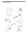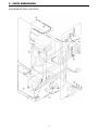
1
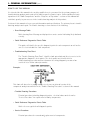
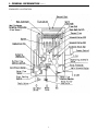
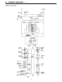
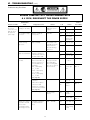
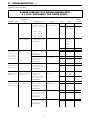
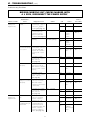
Tankless Gas Water Heater
SERVICE
MANUAL
Troubleshooting Guide
and Instruction for Service
(To be performed ONLY by qualified service providers)
For the LAARS® Heating System
EverHot® Exterior Tankless
Gas Water Heater Models:
IGE-199R-10(N,X)
Document 11014
Save this manual for future reference
IGE-199C-5(N,X)
Key to Warning Symbols
Failure to comply with the following instructions may results in serious personal injury or
damage to the appliance.
Be careful of possible electric shock. Wiring inside this appliance may potentially be at
120 volts.
Disconnect power supply to unit when carrying out the following service repairs.
Read Fault Diagnosis and Wiring Diagram carefully to avoid incorrect wiring.
Do not disassemble. Parts within can not be exchanged or diagnosed faulty.
Please follow the instructions in the following chapters
to ensure safe and appropriate service.
After completing the service and confirming that there are no water or
gas leaks or incorrect wiring, test operation of the appliance.
2
TABLE OF CONTENTS
Section
Description
Page
--Glossary of Terms and Symbols.....................................................
I ......................General Information........................................................................
a. How to Use This Manual. ................................................
b. Cut Away illustration. ......................................................
c. Schematic illustration. .....................................................
II .....................Specifications. (General).................................................................
a. Combustion Specifications..............................................
b. Default Dip Switch Settings.............................................
III ....................Main Components. .........................................................................
IV ....................Safety Device Function. ..................................................................
V .....................Sequence of Operation...................................................................
a. Operation Sequence Flow Chart. ....................................
b. Sequence Timing Chart...................................................
VI ....................Troubleshooting (error messages). .................................................
a. Quick Reference Diagnostic Points. ................................
b. Wiring Diagram ................................................................
c. Troubleshooting Flow Chart. ...........................................
d. Trouble Shooting Procedure. ..........................................
VII ...................Gas Pressure Setting Procedure. ...................................................
VIII ..................Service Procedures. ........................................................................
IX ....................Flushing Procedure for Lime Scale Removal ..................................
X .....................Parts Breakdown ............................................................................
4
5
6
7
8
9
11
12
13
15
17
19
21
23
25
27
29
34
44
46
52
53
Refer to installation and operation manual for the following reference information:
• General Dimensions.
• Piping Recommendations.
• Remote Control Features.
• Water Flow Rates vs Temperature.
3
GLOSSARY OF TERMS AND SYMBOLS
This glossary of terms and symbols is provided to assist you in understanding some of the
language used throughout this manual.
dB(A)
DC
AC
WFCD
FB
Hz
IC
BTU/H
PSI
LED
GPM
mA
W.C.
mm
NOx
OHS
PCB
CPU
POT
rpm
SV
Ø
∆°F
POV
TE
TH
TIN
Tout
-
sound pressure level in decibels, "A" range
direct current
alternating current
water flow control device
feedback information
hertz
integrated circuit
British thermal units per hour
Pounds per square inch
light emitting diode
gallons per minute
milliamps
inches of water column
millimeters
oxides of nitrogen NO & NO2
overheat switch
printed circuit board
central processing unit
potentiometer
revolutions per minute
solenoid valve
diameter
delta T or temperature rise above ambient
modulating valve
thermal efficiency
thermistor
temperature of incoming water
temperature of outgoing water
4
I - GENERAL INFORMATION
This tankless water heater is a high output, high efficiency appliance, which heats the water
continuously as hot water is being drawn for use. Unlike tank type storage water heaters, this water
heater does not store hot water. The burner operates whenever there is a demand for hot water and
is off when the water flow stops. Hot water is continuously supplied for any length of time required,
as long as the specified flow rates are not exceeded. There is no need to set the temperature higher
than required for sufficient capacity. The water heater has sufficient capacity to supply several hot
water faucets simultaneously. The hot water flow capability will be dependent upon the temperature
of the outlet water selected. Operational features of this water heater include:
•
This water heaters is designed to be installed outdoors on an outside wall using the
supplied wall bracket. No indoor space is needed and the water heater can be
mounted at a height convenient for servicing.
•
The burners ignite by direct spark ignition within 3 seconds of detecting minimum
operational water flow. There is no standing pilot.
•
A variable speed combustion air blower forces the combustion air supply into the
burner compartment.
•
No venting system required. For outdoor installation only.
•
An optional recess box is available which allows the water heater to be recessed into
an outside wall and conceal the piping behind a cover for a more attractive installation.
The box enclosure dimensions are: 40 12⁄ " H x 14 34⁄ " W x 9 12⁄ " D. Contact your supplier
to order this optional accessory.
•
The burner flame is continuously monitored and modulated to match the heating
requirements of the water flow. Temperature and flow sensors continually monitor the
water flow and outlet water temperature and adjust the burner and combustion air
blower to maintain temperature.
•
The included, remote mount Main Control may be conveniently located near the point
of use and is adjustable from 96-160°F for residential models or 96-180°F for
commercial models. In addition to the Main Control, up to two optional bathroom
controls are available on the residential models for setting the temperature in the
bathroom fixtures up to 120°F.
•
The Remote Main Control also displays fault codes if the water heater malfunctions to
assist with servicing the water heater.
•
The heat exchanger coil is provided with anti-freeze heaters for cold climate conditions
for protection as low as -30°F (-34°C). Drain solenoids should be installed to drain the
water heater in the event of a power failure. (See installation instructions)
Tools Required for Troubleshooting
Multifunction Digital Test Meter with needle point test leads.
Long reach (12") Magnetic Phillips screw driver (#2 Tip).
3/16 Allen wrench.
Small (pocket size) blade screw driver.
Monometer or Magnehelic inches water column gage.
5
I - GENERAL INFORMATION (cont.)
HOW TO USE THIS MANUAL
It is intended for this manual to be used by qualified service personnel for the primary purpose of
troubleshooting analysis and repair of this tankless gas fired water heater. Understanding the basic
operation of the "Main Components" and the "Sequence of Operation" sections of this manual will
contribute greatly to your success in the troubleshooting analysis of this product.
Sections of this manual reference general information and specifications. The primary focus is trouble
shooting analysis and repair. The trouble shooting section consists of the following:
• Error Message Table
Table showing Error Message as displayed on remote control indicating likely fault and
remedy.
• Quick Reference Diagnostics Points Table
This guide will identify the specific diagnostic point for each component as well as the
correct electrical value for each component.
• Troubleshooting Flow Chart
The "Trouble Shooting Flow Chart" identifies fault potentials and directs service to the
appropriate diagnostic check points. The check points are identified in the
troubleshooting procedure and are shown on the wiring diagram by means of an
encircled letter with a subscript number.
Example:
This chart will also refer to a page number to reference a pictorial version of the
component analysis as outlined in the "Trouble Shooting Procedure" section of this manual.
• Trouble Shooting Procedure
Pictorial procedure including diagnostic points, electrical values and referral to
"Service Procedure" for replacement of faulty components.
• Quick Reference Diagnostics Points Table
Quick reference guide for all diagnostic points.
• Service Procedure
Pictorial procedure for removal and replacement of components.
6
I - GENERAL INFORMATION (cont.)
CUT-AWAY ILLUSTRATION
7
I - GENERAL INFORMATION (cont.)
SCHEMATIC ILLUSTRATION
8
II - SPECIFICATIONS – GENERAL
Type of appliance
Operation
Exhaust system
Model Type
Maximum/Minimum
gas rate (Input Btu's)
Thermal Efficiency
Energy Factor (EF)
Capacity (Gallons 1st
Hour @ 90°F rise)
NOx Emissions (at 3% 02)
Hot water capacity (50°F rise)
Setpoint Temperature
(without remote)
Temperature range
with remote keypads connected
Approved gas type
Installation
Dimensions
Weight
Noise levels
Connections
Ignition system
Electrical consumption
Water temperature control
Water flow control
Recommended Minimum water
supply pressure
Maximum water supply pressure
Temperature controlled continuous flow gas hot water system
With/without remote controls
Direct Vent - Forced combustion
Residential
Commercial
199,000 Btu's – 15,000 Btu's Natural gas
199,000 Btu's – 15,000 Btu's Propane Gas
Natural Gas 84%
Propane Gas 85%
Natural Gas 0.82
Propane Gas 0.84
Natural Gas 218
Propane Gas 227
Less than 40 ppm
0.5 to 6.5 GPM's
Factory setting - 120°F
BC-45-4US 96 - 120°F
MCC-45-4US 96 - 160°F
BSC-45-4US 96 - 120°F
MC-45-4US 96 - 180°F
Natural or Propane – Ensure unit matches gas supply type.
Outdoor installation ONLY
Height 2358⁄ "
Width
1334⁄ "
Depth
878⁄ "
46 Lbs.
49 dB's
3
Gas supply
4
⁄ " MNPT
3
Cold water inlet 4⁄ " MNPT
Hot water outlet 34⁄ " MNPT
Direct electronic ignition
Operating
63 watts
Standby
5.5 watts
Anti-frost protection 84 watts
Simulation feedforward and feedback
Water flow sensor and automatic electro-mechanical water
control device
20 PSI (recommend 50-80 PSI for maximum performance)
150 PSI
9
II - SPECIFICATIONS – GENERAL (cont.)
Power Supply
Safety Devices
Remote control cable
Clearances from combustibles
Clearances from eaves,
porches, overhangs
Appliance – 120 Volts A.C. – 60 Hz.
Remote control 12 volt D.C. (Digital)
Flame failure - Flame rod
Boiling protection - 203˚F
Remaining flame (OHS) 194˚F bi-metal switch
Fusible link
Automatic frost protection
- Bimetal sensor & anti-frost heaters
Combustion fan rpm check - integrated circuit
Over current - Glass fuse (3 amp)
Non-polarized two core cable
Top of heater
12"
Front of heater
24"
Sides of heater
6"
Back of heater
0"
Ground
12"
Installations within RGB-25 Recess Box: Clearances
from combustibles to recess box top, bottom, back and
sides = 0"
Top of heater
36"
10
II - SPECIFICATIONS (cont.)
COMBUSTION SPECIFICATIONS
Item
Gas Consumption
Injector Diameter
Inches (mm)
Main Burner
Main Damper
Gas Pressure
Supply/Manifold
Gas Type
Natural
Propane
Minimum Btu's
15,000
15,000
Maximum Btu's
199,000
199,000
Upper
ø.045 (1.15mm)
ø.029 (.75mm)
Lower
ø.070 (1.8mm)
ø.045 (1.15mm)
B3A7-1 (Lean and Rich Bunsen Burner)
H73-115 (Upper: ø6, Lower: Not Used)
Minimum Supply
Maximum Supply
Low Fire Manifold
High Fire Manifold
11
6" W.C.
10.5" W.C.
0.56" W.C.
3.4" W.C.
10" W.C.
13.5" W.C.
0.88" W.C.
5.1" W.C.
II - SPECIFICATIONS (cont.)
DIP SWITCH SETTINGS
DANGER
Do not attempt to adjust dip switch settings from there factory default settings.
Doing so will result in damage to unit, property damage, personal injury or death.
Contact Technical Support for information pertaining to dip switch function.
FACTORY DEFAULT SETTING, RESIDENTIAL UNITS
Natural Gas Model
Dip Switch Settings:
(SW1)
(SW2)
#1 = Off
#1 = On
#2 = On
#2 = Off
#3 = Off
#3 = Off
#4 = Off
#4 = Off
#5 = Off
#6 = Off
#7 = Off
#8 = Off
Propane Gas Models
Dip Switch Settings:
(SW1)
(SW2)
#1 = Off
#1 = Off
#2 = On
#2 = Off
#3 = Off
#3 = Off
#4 = Off
#4 = Off
#5 = Off
#6 = Off
#7 = Off
#8 = Off
FACTORY DEFAULT SETTING, COMMERCIAL UNITS
Natural Gas Models
Dip Switch Settings:
(SW1)
(SW2)
#1 = Off
#1 = On
#2 = On
#2 = Off
#3 = Off
#3 = Off
#4 = Off
#4 = On
#5 = Off
#6 = Off
#7 = Off
#8 = Off
Propane Gas Models
Dip Switch Settings:
(SW1)
(SW2)
#1 = Off
#1 = Off
#2 = On
#2 = Off
#3 = Off
#3 = Off
#4 = Off
#4 = On
#5 = Off
#6 = Off
#7 = Off
#8 = Off
12
III - MAIN COMPONENTS
1. Mechanical Water Regulator
The unique water regulator mechanism ensures the hot water is maintained with no noticeable
change to the desired temperature during use, even if water pressure drops due to another tap being
turned on and increasing the demand.
2. Preset Bypass
A preset volume of cold water is mixed with water heated in the heat exchanger.
3. Burner
The burner assembly is made up of 16 identical stainless steel
Bunsen burners, secured by an aluminized steel framework.
An aluminum manifold with 32 integral injectors supplies gas
to the burners, and is attached to the front lower cover of the
burner box and gas control assembly.
4. Gas Control Valve
The gas control valve uses four solenoids to fully modulate within four different input ranges to
respond quickly and accurately to changes in water flow rate. The four ranges are as follows: up to
18% of total btu's (using three burners), up to 33% (using five burners), up to 50% (using eight
burners, and up to 100% (using sixteen burners) This increases the flexibility of the regulator/
modulating valve by supplying gas equally to each burners.
13
III - MAIN COMPONENTS (cont.)
5. Combustion Fan
Air for the combustion is supplied by a centrifugal fan
driven by a DC motor. After a pre-purge period of 0.2
seconds, the fan speed is controlled by the PCB to
provide the correct volume of air for combustion. The
calculation for the fan speed is based upon incoming
water temperature, water flow and the temperature
selected on the remote controls.
The actual speed of the motor is continuously monitored
by a magnetic pulse sensor.
This sensor emits (4) pulses per rotation of the fan. This is
the fan feedback or confirmation data processed by the PCB.
The fan speed is constantly correcting to provide optimum combustion conditions. In addition,
the fan speed will determine the opening degree of the modulating gas valve. This enables the
gas rate to always match the volume of air for combustion, as well as the input required to
heat the water.
1. Water Flow Sensor and Water Flow Control device
Water flow is detected by a turbine/magnetic pulse generating device. Water flows through the
turbine/magnetic sensor providing information to the PCB by generating a pre-determined number of
pulses in proportion to the water flow. These pulses are counted by the PCB – no pulse indicates no
water flow. The frequency of the magnetic pulses increases as the water flow increases, this enables
the PCB to calculate the exact water flow, and determine the water flow in gallons per minute. As
soon as the required water flow is detected, the PCB activates the combustion fan. The combustion
fan speed is monitored by a magnetic pulse sensor. The output from this sensor is processed by the
PCB which opens the gas modulating valve to a degree proportional to the fan speed.
See above for further details on the combustion fan.
The water flow control consists of a plug and barrel valve which is rotated by a motor to increase or
decrease the volume of water passing through the heat exchanger.
Automatic water flow control device
14
IV - SAFETY DEVICE FUNCTION
Flame Failure
Situated to the right of the burner in the front of the combustion chamber, the flame rod monitors the
combustion process. This sensor monitors the flame intensity, while the PCB compares this signal to
the feed back signal from the combustion fan motor, water flow control, and gas flow through the POV
valve. If any one of the feedback signals are incorrect, the unit will shut off, preventing discharge of
gas to the burner.
Over Heat Protection Device
Also referred to as an Over Heat Switch. This device is fitted to a bend section at the left side of the
heat exchanger. If the flame remains on to the burner after the tap is closed and the water
temperature inside the heat exchanger reaches 194° F, a 12 volt DC bi-metal cut-off switch will shut
off the gas supply to the solenoids.
No Water
Should the incoming water flow become restricted or stop, the water flow sensor will cease to send a
magnetic pulse signal to the PCB, in turn preventing gas to flow into the combustion chamber. If you
have restricted flow, first check to ensure the inline water filter is not clogged.
Thermal Fuse (Non-Resettable)
Wrapped around the entire surface of the heat exchanger you will find a thermal fuse. This device
activates in the event of excessive heat exchanger temperature or the temperature outside the heat
exchanger reaches 264 °F. If the thermal fuse melts, it breaks an electronic circuit which in turn shuts
off the power supply to the gas solenoids, deactivating the unit.
Combustion Fan Revolution Check
The combustion fan rpm's are continually monitored by a magnetic pulse generator connected to the
PCB. If the fan revolutions deviate from the speed required for complete combustion, a signal is sent
to the PCB and the revolutions adjust accordingly. (If not the unit deactivates)
Automatic Frost Protection
When the temperature inside the appliance drops below 37°F , the frost sensing device inside the
appliance activates the anti-frost heaters to prevent the water inside the unit from freezing. The
antifrost heaters remain ON until the temperature inside the appliance rises to 57°F. There are five
(16) watt anti-frost heaters located at various points throughout the main water flow area of the
appliance. The unit also incorporates the ability to fire for (3) seconds in the event the anti-frost
heaters can not keep the water temperature from dropping below 37°F. This unique feature will heat
the water in the lines inside the appliance back up to 57°F. Both of the above features function as
long as the unit has power and gas. There is an optional freeze protection system that can be
added to the unit's piping. See the auto drain down drawing in the product Owner's manual for
instructions on how to install the option freeze protection in the event of a power failure in cold
climates.
15
IV - SAFETY DEVICE FUNCTION (cont.)
Over temperature Cut-Off
The temperature of the outgoing hot water is constantly monitored by the water temperature
thermistor located near the outlet of the appliance. If the outgoing water temperature reaches 5 °F
above the preset temperature, the burner will automatically deactivate. The burner will ignite again
when the outgoing hot water temperature falls below the preset temperature.
16
V - SEQUENCE OF OPERATION
The preset temperature is selected at one of the remotes controls (where fitted). Where no remote
control is fitted , the default temperature can be set at 108, 120, 130, 140, 150, 160, 170, or 180 °F.
To select one of the above temperatures as your default setting, you MUST obtain written permission
and training. (Contact your technical service group)
When the unit is first plugged into 120 volts, the PCB assumes an incoming water temperature of
77°F. This prevents the appliance from starting in "High fire" and producing very hot water the first
time it is used.
The data used to determine the outgoing water temperature, initially, is incoming water flow and the
remote control pre-set temperature.
From the incoming water flow and remote control pre-set temperature data, the CPU is able to
determine a suitable gas rate to initiate the appliance operation once a hot water tap opens.
The calculation of temperature rise and water flow is called simulation feed-forward.
The water heater calculates incoming water temperature by subtracting the theoretical temperature
rise from the outgoing hot water temperature to establish the correct gas flow.
When a hot water tap is opened, water begins to flow through the water heater. The turbine in the
water flow sensor begins to revolve. The revolution speed is proportional to the water flow. A sensor
located inside the device relays information in the form of magnetic pulses to the main PCB to
determine whether or not water is flowing, and also, the volume of water flowing. When a
predetermined water flow is sensed, the ignition sequence begins.
The combustion fan pre-purges the combustion chamber. A rev counter on the combustion fan
indicates the fan rpm to the main PCB. When the pre-purge cycle is completed, the PCB controls the
fan rpm by varying the DC voltage to the fan motor. This maintains the correct air/gas ratio
throughout the time the water heater is in use and ensures proper combustion.
The gas is ignited by direct spark and the flame is sensed by the flame rod. The opening degree of
the modulating valve is determined by the combustion fan speed.
The changeover valve directs gas to one side or both sides of the burner. At the point where the
changeover valve opens or closes the modulating valve is instantly re-adjusted by the PCB to
compensate for the change in the number of burners in use. From the information provided by the
water flow sensor and the water temperature thermistor, the PCB determines how much gas is
required to heat the water to the temperature selected on the remote control.
The PCB is programmed to provide the maximum volume of water possible at a given temperature
rise. As the water flow from the tap is increased, the PCB increases the gas and air flow to the burner.
17
V - SEQUENCE OF OPERATION (cont.)
When the hot water tap is turned off, the water flow sensor stops revolving, and the magnetic pulse
ceases, indicating to the PCB that there is no water flowing, in turn the PCB closes the gas valves. The
combustion fan continues to operate for 65 seconds. This will provide quicker ignition when the tap is
turned on and off in rapid succession, and removes the need for a pre-purge cycle allowing the burner
to re-light immediately when a hot water tap is opened again.
18
V - SEQUENCE OF OPERATION (cont.)
OPERATION SEQUENCE FLOW CHART
19
V - SEQUENCE OF OPERATION (cont.)
OPERATION SEQUENCE FLOW CHART
20
V - SEQUENCE OF OPERATION (cont.)
SEQUENCE TIMING CHART
21
V - SEQUENCE OF OPERATION (cont.)
SEQUENCE TIMING CHART
22
VI - TROUBLESHOOTING
ERROR MESSAGES
Error
10
Faulty
Air Supply or Exhaust Blockage
11
No Ignition
12
Flame Failure
14
Thermo Fuse
16
Over Temperature Warning
Remedy
Check intake and exhaust ports for obstructions.
Check that nothing is blocking the flue inlet or exhaust.
Did you maintain the proper clearance from combustibles
around the unit?
Ensure you have gas to the appliance.
Ensure gas type and pressure is correct.
Bleed all air from gas lines.
Verify dip switches are set properly.
Disconnect all MSA controls.
Ensure gas line, meter, and/or regulator is sized properly.
Ensure appliance is properly grounded.
Check gas solenoid valves for open or short circuits.
Ensure igniter is operational.
Check igniter wiring harness for damage.
Ensure you have gas to the appliance.
Ensure gas type and pressure is correct.
Bleed all air from gas lines.
Verify dip switches are set properly.
Ensure flame rod wire is connected.
Check flame rod for carbon build-up.
Ensure gas line, meter, and/or regulator is sized properly.
Ensure appliance is properly grounded.
Check gas solenoid valves for open or short circuits.
Check power supply for loose connections.
Check power supply for proper voltage and voltage drops.
Disconnect all MSA controls.
Disconnect keypad.
Disconnect and re-connect all wiring harnesses on unit and PC
board.
Immediate code 12 usually indicates a defective gas valve
or power supply problem.
Ensure dip switches are set to the proper position.
Ensure high fire and low fire manifold pressure is correct.
Check gas type of unit and ensure it matches gas type
being used.
Check heat exchanger for cracks and/or separations.
Check resistance on safety circuit.
Check for improper conversion of product.
Check for restrictions in air flow around unit and vent
exhaust discharge.
Check for a low flow circulating system that is causing the
unit to short cycle.
Check for a foreign materials in combustion chamber
and/or exhaust piping.
Check for clogged heat exchanger.
Check for restrictions in air flow around unit and vent terminal.
Check for a low flow circulating system that is causing the unit
to short cycle.
Check for foreign materials in combustion chamber and/or
exhaust.
23
VI - TROUBLESHOOTING (cont.)
ERROR MESSAGES
Error
32
Faulty
Outgoing Water
Temperature Sensor Faulty
33
Heat Exchanger Outgoing
Temperature Sensor Faulty
34
Combustion Air
Temperature Sensor Faulty
52
Modulating Solenoid Valve
Signal Abnormal
61
Combustion Fan Failure
71
SV0, SV1, SV2, and SV3
Solenoid Valve Circuit Faulty
72
Flame Sensing Device Faulty
LC
Scale Build-up in Heat Exchanger
No
Code
Nothing happens when water flow
is activated
Remedy
Check sensor wiring for damage.
Check resistance on sensor.
Check and clean scale from sensor.
Replace sensor.
Check sensor wiring for damage.
Check resistance on sensor.
Check and clean scale from sensor.
Replace sensor.
Check sensor wiring for damage.
Check resistance on sensor.
Check and clean dirt from sensor.
Ensure fan blade is tight on motor shaft and it is in good
condition. Clean blower blades if dirty.
Check for restrictions in air flow around unit and vent terminal.
Replace sensor.
Check modulating gas solenoid valve wiring harness for loose
or damage terminals.
Check resistance on solenoid valve.
Ensure fan motor will turn freely. Motor will operate with a
small amount of restriction.
Check wiring harness to motor for damaged and/or loose
connections.
Check resistance on motor winding.
Check wiring harness to all solenoids for damage and/or loose
connections.
Check resistance on each solenoid.
Check micro amps produced by flame rod.
Remove flame rod and check for carbon build-up, clean with
sand paper.
Ensure flame rod is touching flame when unit fires.
Check inside burner chamber for any foreign material blocking
flame at flame rod.
Check all wiring to flame rod for damage.
Replace flame rod.
Turn off power supply, then reapply power; if code does not
reappear separate control wires from the unit's power supply.
Flush heat exchanger.
Replace heat exchanger.
Clean inlet water supply filter.
Ensure you have at least the minimum flow rate required to fire
unit.
Check for pipe dope inside water flow control turbine.
On new installations ensure hot and cold water lines are not
crossed.
Check for bleed over. Isolate unit from building by turning off
hot water line to building, then open your pressure relief valve.
If unit fires, there's a bleed over in your plumbing.
If a circulating system is in use, it must be isolated also.
Remote control does not light up but you have 12 VDC at the
terminals for controls.
Disconnect water flow control motor, then turn on hot water, if
unit fires replace water flow control assembly.
Check resistance on water flow control sensor.
24
VI - TROUBLESHOOTING (cont.)
QUICK REFERENCE DIAGNOSTIC POINTS
IMPORTANT SAFETY NOTES:
There are a number of (live) tests that are required when fault finding this product. Extreme care
should be used at all times to avoid contact with energized components inside the water heater.
Only trained and qualified service agencies should attempt to repair this product.
Remember, before checking for resistance readings, you should disconnect the power source
(unplug it) to the unit and isolate the item to be checked from the circuit.
(TR) Transformer:
Wire color
Black ~ White
Blue ~ Brown
Voltage
100 ~ 120 VAC
110 ~ 120 VAC
Resistance
51 ~ 63 ohms
51 ~ 63 ohms
Connector #
F9
F7
Pin #'s
1~2
1~3
(SV0, SV1, SV2, SV3 and POV) Gas valve and Modulating solenoids: (Set meter above 2K)
(SV0) Pink ~ Black 80 ~ 100 VDC
1,8K ~ 2K ohms
E1
1~2
(SV1) Black ~ Yellow 80 ~ 100 VDC
1,8K ~ 2K ohms
E2
2~3
(SV2) Black ~ Blue 80 ~ 100 VDC
1,8K ~ 2K ohms
E3
2~4
(SV3) Black ~ Brown 80 ~ 100 VDC
1,8K ~ 2K ohms
E4
2~5
(POV) Pink ~ Pink
2 ~ 15 VDC
67 ~ 81 ohms
C2
3~4
(M) Water Flow Control Device Servo or Geared Motor:
Red ~ Blue
11 ~ 13 VDC
22 ~ 26 ohms
Grey ~ Brown
4 ~ 6 VDC
N/A
Grey ~ Yellow
N/A
N/A
Grey ~ Orange
11 ~ 14 VDC
N/A
B2
B2
B2
B2
9 ~ 10
5~7
5~8
5~6
NOTE: The grey wire listed above turns to black at B connector on the PCB, the orange wire turns to red.
(QS) Water Flow Sensor:
Black ~ Red
11 ~13 VDC
Yellow ~ Black
4 ~ 7 VDC
5.5K ~ 6.2K
1 meg ~ 1.4 meg
B4
B4
5~6
1~5
By-pass Flow Control:
Brown ~ White
2 ~ 6 VDC
Orange ~ White
Yellow ~ White
Red ~ White/Ground
Unit in operating
mode
15 ~ 35K
G4 ~ G5
G2 ~ G5
G1 ~ G5
4~5
2~5
1~5
3~5
(IG) Ignition System:
Grey ~ Grey
90 ~ 100 VAC
N/A
F8
2~3
(FM) Combustion Fan Motor:
Red ~ Black
6 ~ 45 VDC
White ~ Black
6 ~ 45 VDC
Yellow ~ Black
11 ~ 13 VDC
N/A
9.2K ~ 9.4K
3.5K ~ 3.9K
A1
A1
A1
1~2
2~4
2~3
Set your meter to the Hertz scale. Reading across the red and yellow wires at terminals 2 and 3 you
should read between 60 and 350 Hertz.
25
VI - TROUBLESHOOTING (cont.)
Thermal Fuse:
Red ~ Red
100 VAC
Below 1 ohm
B~C
B6 ~ C1
Overheat Switch:
Red ~ Red
100 VAC
Below 1 ohm
B~C
B6 ~ C1
Flame Rod:
Place one lead of your meter to the flame rod and the other to earth or ground. With the unit running
you should read between 5 ~ 150 VAC. Set your meter to the µ amp scale, series your meter in line
with the flame rod. You should read 1µ or greater for proper flame circuit. In the event of low flame
circuit remove the flame rod and check for carbon and/or damage.
Heat Exchanger, Air Temperature, and Outgoing Water Temperature Thermistors:
Check all thermistors by inserting meter leads into each end of the thermistor plug. Set your meter to
the 20K scale and read resistance. You should be able to apply heat to the thermistor bulb and see
the resistance decrease. Then apply some ice to the thermistor and the resistance should increase.
See below for examples of temperatures and resistance reading at those temperatures.
Example:
59°F = 11.4 ~ 14K
86°F = 6.4 ~ 7.8K
113°F = 3.6 ~ 4.5K
140°F = 2.2 ~ 2.7K
221°F = 0.6 ~ 0.8K
Outgoing Water Thermistor:
White ~ White
N/A
See example above
B
B3 ~ B4
Heat Exchanger Temperature Thermistor:
White ~ Pink at board
N/A
See example above
B
B3 ~ B12
Surge Protector:
Black ~ White
108 ~ 132 VAC
N/A
Surge Protector D1
1~3
Blue ~ Brown
108 ~ 132 VAC
N/A
Surge Protector D2
1~2
With the power off you can check the continuity through the surge protector. Place one meter lead on
the top pin #1 of the surge protector and pin #2 on the bottom of the surge protector. Then check
across top pin #3 and bottom pin #1, if you read continuity across these two points the surge
protector is good. If you do not get continuity, replace the surge protector.
Remote Controls:
Terminals D1
10 ~ 13 VDC digital 1.5K ~ 1.9K ohms
H
1~3
Frost Protection:
This unit has four frost protection heaters mounted at different points inside the unit to protect the
water heater from freeze ups. There are two heaters located on the outlet hot water line next to the
thermistor.
26
VI - TROUBLE SHOOTING (cont.)
Using a voltage meter set to the 200 ohm scale, you should have a resistance reading of 26 - 30
ohms through each of these heaters. The heater located on the heat exchanger piping should have a
resistance reading of 81 – 86 ohms and the one located in the water flow sensor valve has a
resistance reading of 16 – 19 ohms. Voltage throughout this circuit should be 120 VAC.
Fuses:
This unit has 2 in line (3) amp glass fuses. Remove the fuse and check continuity through them. If you
have continuity through the fuse, it is good. If you cannot read continuity, the fuse is blown and must
be replaced.
WIRING DIAGRAM
27
VI - TROUBLE SHOOTING (cont.)
WIRING SCHEMATIC
28
VI - TROUBLESHOOTING (cont.)
Troubleshooting Flow Chart
BEFORE CARRYING OUT CHECKS MARKED WITH
A # SIGN, DISCONNECT THE POWER SUPPLY.
Nature of Fault
A. The LED on
the remote
control does not
light up, when
the system is
powered up
Examination
Point
1. Do you have
voltage to the unit?
2. Is supply voltage
correct?
3. Check surge
protector.
4. Check both 3
amp electrical fuses.
5. Check for short
circuits.
Diagnostic Point
Values
Y/N
Action
Do you have 120
VAC at the power
supply?
Yes
Go to A – (2)
No
Plug in cord
120 VAC
Yes
Go to A – (3)
No
Check power
supply circuit.
Check fuses.
Do you have 120
volts AC across the
blue and brown
wires at the surge
protector?
Yes
Go to A – (4)
No
Go to A – (5)
# Disconnect and
measure resistance to
confirm if fuse is blown.
Normal < than 1 MΩ
Is fuse blown?
Yes
Go to A – (5)
replace fuse
Go to A – (6)
1. Measure resistance of
each solenoid valve. #
Remove connector E
from the PCB before
measuring.
Pink ~ Black (SV0)
1.7 ~ 2.1KΩ
Yellow ~ Black (SV1)
1.7 ~ 2.1KΩ
Brown ~ Black (SV2)
1.7 ~ 2.1KΩ
(See page 38)
1. Measure the
resistance.
# Disconnect sparker
connector F8 and
measure the resistance
between both terminals.
(See page 37)
3. Check wiring.
Are valves within
those specified at
left? # Measure
after checking that
there are no broken
wires or shorts.
Power source
Measure voltage at
power point.
Inspect visually
No
Yes
Go to
A – (6) - 2
No
Replace gas
valve.
Is resistance >1MΩ ? Yes
Are there any
shorts?
Service
Procedure
IGE – 9
Go to
A (5 – 3)
No
Replace
sparker.
Yes
Rectify
/Replace
No
Replace PCB
IGE – 4
IGE – 2
6. Check to ensure
you have 120 VAC
across both
terminals feeding
the surge protector.
100 ~ 120 VAC
1. Measure voltage at
the blue and brown
wires.
29
Yes
Go to A (6 – 2)
No
Check for
proper voltage
to unit.
VI - TROUBLESHOOTING (cont.)
Troubleshooting Flow Chart
BEFORE CARRYING OUT CHECKS MARKED WITH
A # SIGN, DISCONNECT THE POWER SUPPLY.
Nature of Fault
Examination
Point
Values
Diagnostic Point
2. Measure the voltage
at connector F with
appliance power supply
on.
7. Check remotes (s)
(where connected.)
Y/N
Action
Are values within
those specified at
left.
Yes
Go to A – (7)
No
Replace
transformer
11 ~ 13 VDC Digital
Yes
1. Measure voltage
between red ~ black of
connector B4.
(See page 35)
2. Measure voltage
between yellow ~ black
at connector B4.
(See page 35)
11 ~ 13 VDC
No
Yes
No
Check cable
for shorts or
broken wires.
Replace
remote
control.
Replace PCB.
Go to B–1-2
Replace PCB.
4 ~ 7 VDC
Yes
No
Go to B - 2
Replace water
flow sensor.
F – Black ~ White
100 ~ 120 VAC
F7 – Blue ~ Brown
100 ~ 120 VAC
Measure voltage
between remote control
terminals at D.
Service
Procedure
IGE – 7
IGE – 2
B. Digital monitor
lights up, but
combustion does
not commence.
(when remotes
are connected).
1. Check water flow
sensor.
Error code "72"
displayed on the
digital monitor.
2. Check flame rod
# Measure resistance
between flame rod
terminal C1 and earth.
(See page 36)
Resistance > 1MΩ?
Yes
No
Replace PCB
Replace flame
rod
IGE – 2
Error code "32"
displayed on the
digital monitor.
3. Check outgoing
water temperature
thermistor.
# Disconnect connector
B5 and measure
resistance.
Open circuit: > 1MΩ
Short circuit: < 1Ω
(See page 36)
Are values as shown
at left?
Yes
IGE – 6
No
Replace water
temperature
thermistor.
Go to B - 4
1. Check motor.
Measure voltage
between black ~ red at
connector A1.
(See page 37)
2. Check fan rotation
sensor. Measure voltage
between black ~ yellow
at connector A1.
(See page 37)
6 ~ 45 VDC (Fan on)
0 VDC (Fan off)
Yes
No
Go to B – 5-2
Replace PCB
IGE – 2
11 ~ 13 VDC
Yes
No
Go to B – 4-3
Replace PCB
IGE – 2
3. Measure voltage
between black ~ white
of connector A1.
(See page 37)
6 ~ 45 VDC
Yes
No
Go to B – 5
Replace fan
IGE – 5
Error code "61"
displayed on the
digital monitor.
4. Check
combustion fan.
30
IGE – 2
IGE – 3
VI - TROUBLESHOOTING (cont.)
Troubleshooting Flow Chart
BEFORE CARRYING OUT CHECKS MARKED WITH
A # SIGN, DISCONNECT THE POWER SUPPLY.
Nature of Fault
Error code "11"
displayed on
digital monitor.
Examination
Point
5. Check ignition
module.
Values
1. Measure voltage
between grey ~ grey of
connector F8 (ignition
module).(See page 37)
2. # Remove connector
F8 and measure the
resistance between
ignition module and
terminals. (See page 37)
3. Check if unit is
sparking.
6. Check main gas
solenoid valve (SV0)
Error code 71
7. Check solenoid
valve (SV1)
8. Check
changeover solenoid
valve (SV2)
Error code "14"
displayed on
digital monitor
Diagnostic Point
9. Check thermal
fuse
10. Check overheat
(remaining flame) bimetal switch
90 ~ 110 VAC
Is resistance >1MΩ?
Is the ignition
module sparking?
1. # Disconnect the main
solenoid valve connector
E from the PCB, and
measure the resistance
between pink ~ black
(SV0)
1.7 ~ 2.1KΩ
2. Measure voltage
between pink ~ black of
SV0 connector.
(See page 38)
Y/N
Action
Yes
Go to B-5-2
No
Replace PCB
Yes
No
Go to B-5-3
Adjust/
Replace
ignition
module
Yes
Go to B-6
No
Adjust/
Replace
electrode
Go to B-6-2
Yes
Service
Procedure
IGE – 2
IGE – 4
No
Replace gas
valve
80 ~ 100 VDC
Yes
No
Go to B-7
Replace PCB
1. # Disconnect
connector E from the
PCB. Measure resistance
between yellow ~ black
of (SV1).
1.7 ~ 2.1KΩ
Yes
Go to B-7-2
No
Replace gas
valve
2. Measure voltage
between yellow ~ black
of SV1 connector.
(See page 38)
80 ~ 100 VDC
Yes
No
Go to B-8
Replace PCB
1. # Disconnect
connector E from the
PCB. And measure
resistance between blue
~ black (SV2)
1.7 ~ 2.1KΩ
Yes
Go to B-8-2
No
Replace gas
valve
2. Measure the voltage
between blue ~ black or
SV2 connector.
(See page 38)
80 ~ 100 VDC
Yes
No
Go to B-9
Replace PCB
IGE – 2
1. # Disconnect
connector B3 and C3
measure resistance
between red ~ red.
2. # Disconnect OHS
(remaining flame) bimetal switch festoon
terminal B3 and C3, and
measure resistance
between terminal on
switch. (See page 40)
Is resistance < 1Ω?
Yes
Go to B-10
Replace
thermal fuse
IGE – 11
Yes
Replace PCB
IGE – 2
No
Replace
remaining
flame bi-metal
switch
31
No
Is resistance < 1Ω?
IGE – 9
IGE – 2
IGE – 9
IGE – 2
IGE – 9
VI - TROUBLESHOOTING (cont.)
Troubleshooting Flow Chart
BEFORE CARRYING OUT CHECKS MARKED WITH
A # SIGN, DISCONNECT THE POWER SUPPLY.
Nature of Fault
C. Combustion
occurs, but flame
fails.
Error code "12"
displayed on
digital monitor.
Examination
Point
1. Check flame rod.
2. Check ground
wire.
Diagnostic Point
Values
1. Measure the voltage
between flame rod
terminal C1 and
appliance ground.
2. Check to ensure flame
rod bracket is not loose.
5 ~ 150 VAC
Check for faulty ground
wire connections at unit,
receptacle, and ground
rod to home, and for
broken or shorted wires.
Are connections
OK?
Is it secure?
Y/N
Yes
No
Go to C-1-2
Replace PCB
Yes
No
Go to C-2
Replace/
rectify
Yes
Check for
other causes
of flame
failure.
Replace or
repair
grounding
circuit to unit.
No
D. Cannot adjust
water
temperature.
Action
Service
Procedure
IGE – 2
1. Check hot water
thermistor.
(outgoing
thermistor)
# Disconnect connector
B5 and measure the
resistance between
white ~ white.
(See page 41)
Resistance values
match table on page
#41
Yes
No
Go to D – 2
Replace water
temperature
thermistor.
2. Check
changeover solenoid
valve (SV3).
1. # Disconnect
connector E from PCB
and measure the
resistance between
brown ~ black.
(See page 39)
1.7 ~ 2.1KΩ
Yes
No
Go to D – 2-2
Replace
manifold
assembly
2. Measure the voltage
between brown ~ black
wire of the changeover
solenoid valve (SV3) at
connector E.
(See page 39)
80 ~ 100 VDC
Yes
No
Go to D – 3
Replace PCB
IGE – 2
1. # Disconnect
modulating valve at C2
festoon terminal and
measure resistance at
solenoid terminals.
(See page 42)
2. Measure the voltage
between two harness
terminals at C2.
(See page 42)
3. Check whether the
manifold pressure alters
when remote control
temperature is altered
between 96° ~ 140°F.
1, # Measure resistance
between red ~ blue
wires of the water flow
servo connector B2.
(See page 42)
67 ~ 81Ω
Yes
No
Go to D – 3-2
replace gas
valve
IGE – 9
Yes
No
Go to D – 3-3
Replace PCB
Does the manifold
pressure change?
Yes
No
Go to D – 4
Replace gas
valve
22 ~ 26Ω
Yes
No
3. Check
modulating valve.
4. Check water flow
servo.
32
2 ~ 15 VDC
Go to D – 4-2
Replace water
flow servo
sensor.
IGE – 6
IGE – 8
IGE – 2
IGE – 9
IGE – 3
VI - TROUBLESHOOTING (cont.)
Troubleshooting Flow Chart
BEFORE CARRYING OUT CHECKS MARKED WITH
A # SIGN, DISCONNECT THE POWER SUPPLY.
Nature of Fault
Examination
Point
Diagnostic Point
Values
2. Measure voltage
between orange (+) and
grey (-) of the water flow
servo connector B2.
3. Measure voltage
between brown ~ grey
of water flow servo
connector B2 (Don not
turn water on)
(See page 42)
4. Measure voltage
between yellow ~ grey
of the water flow servo
connector B2 (Do not
turn water on)
(See page 42)
E. Anti-frost
heater does not
work.
1. check anti-frost
heater.
2. Check frost
sensing switch
11 ~ 13 VDC
4 ~ 6 VDC
4 ~ 6 VDC
Y/N
Action
Yes
No
Go to 4-3
Replace PCB
Yes
No
Go to D-4-4
Replace water
flow servo
sensor.
Yes
No
Normal
Replace water
flow servo
sensor.
1. # Disconnected
connector F4 and F5
measure resistance
across each of the
heating elements. (white
wires)
(See page 43)
348 ~ 375Ω
Yes
No
Go to E-1-2
Replace Antifrost sensing
switch.
2. # Read resistance of
the heating element that
is mounted on the front
of the heat exchanger.
(white wires)
(See page 43)
100 ~ 110Ω
Yes
No
Go to E-2
Replace Antifrost heater
that is
defective.
3. Read resistance of
heating elements on the
heat exchanger outlet
hot water line.
(See page 43)
33 ~ 39Ω
Yes
No
Go to E-2
Replace Antifrost heater
that is
defective.
# Disconnect connector
F2 and measure across
the bi-metal sensing
switch located on the
upper right hand of the
heat exchanger. check
this switch at
temperatures below 37
°F. You can place an ice
cube against the switch
to activate it.
(See page 43)
Is resistance <1Ω
after applying ice to
this switch for five
minutes?
Yes
No
Check wiring
Replace Antifrost sensing
switch.
33
Service
Procedure
IGE – 2
IGE – 3
IGE – 3
VI - TROUBLESHOOTING (cont.)
Troubleshooting Procedure
BEFORE CARRYING OUT CHECKS MARKED WITH A # SIGN, DISCONNECT THE POWER SUPPLY.
Unit’s wiring diagram can be found on page 27.
Appliance fails to operate (even remote control fails to operate).
1) Is the fuse blown?
Check fuse.
a.
Disconnect unit from power supply.
b.
# Measure resistance to check the electric fuse
(3 amp)
Fuses are located in plastic
holders in the main harness,
Normal: less than 1Ω
on the lower right hand side
If normal, proceed to check item 2 below.
of the appliance.
Faulty: Replace 3 amp glass fuse. If the fuse
blows again, investigate cause of short circuit.
2) Is the main transformer normal?
Check the transformer.
a.
Measure the voltage and/or resistance at
connector F, black ~ white wires.
Normal: 100 ~ 120 VAC
51 ~ 63 Ω resistance
Faulty: Check for 120 ~ 125 VAC at the surge
protector, blue ~ brown wires, connector
F7 .
Resistance reading 51 ~ 63 Ω
If normal, check item 3 on next page.
Faulty: Replace the transformer.
(Service Procedure IGE-7, page 49)
34
VI - TROUBLESHOOTING (cont.)
3) Is the remote control normal?
Check voltage between the two remote control cable
connectors.
a.
Check the voltage between terminals on the
remote control terminal mount D1.
Normal: 11 ~ 13 VDC
If normal, check for an open circuit or short before
replacing the remote control.
Faulty: Replace PCB.
(Service Procedure IGE-2, page 47)
No combustion (despite remote control indication)
1) Is the water flow sensor normal?
Check the water flow sensor.
a.
Check the voltage at PCB connector B4 , red and
black wires.
Normal: 11 ~ 13 VDC or 5.8 ~ 6.4K Ω
If normal, check (b) below.
Faulty: Replace the PCB.
(Service Procedure IGE-2, page 47)
b.
Check the voltage at PCB connector B4, yellow and
black wires.
Normal: 4 ~ 7 VDC or 1M ~ 1.2M Ω.
If normal, proceed to check item 2 on next page.
Faulty: Replace the water flow sensor.
(Service Procedure IGE-2, page 47)
35
VI - TROUBLESHOOTING (cont.)
BEFORE CARRYING OUT CHECKS MARKED WITH A # SIGN, DISCONNECT THE POWER SUPPLY.
2) Is the flame rod normal? Error “72” is displayed
Checking the flame rod.
a.
# Detach the flame rod terminal C1, and re-attempt
operation.
(“72 is displayed)
Proceed to check item 3 below.
(no “72” displayed)
Inspect flame rod wiring for current leak and inspect
flame rod for carbon build-up.
Measure resistance between the flame rod
Terminal C1 and the appliance earth.
Normal: 1 M Ω or more.
If normal, replace the PCB unit.
(Service Procedure IGE-2, page 47)
Faulty: Replace the flame rod.
See page 40 for additional information and resistance values
pertaining to the flame rod.
3) Is the water temperature thermistor normal?
If error “32” is displayed, check the water
temperature thermistor.
a.
# Disconnect connector B5, and measure resistance of
the white ~ white wires.
Resistance > 1 M Ω = open circuit.
Resistance < 1 Ω = short circuit.
Normal: Proceed to check item 4 on the next page.
Faulty: Replace the water temperature thermistor.
(Service Procedure IGE-6, page 48)
See page 41 for additional information and
resistance readings pertaining to the
temperature themistor.
36
VI - TROUBLESHOOTING (cont.)
BEFORE CARRYING OUT CHECKS MARKED WITH A # SIGN, DISCONNECT THE POWER SUPPLY.
4) Is the combustion fan motor normal?
Motor check.
If error “61” is displayed, check the combustion fan.
a.
Measure voltage at connector A1. Black and red wires.
Normal: 6 ~ 45 VDC (Fan on)
0 VDC (Fan off)
If normal, check item b below.
Faulty: Replace the PCB unit.
(Service Procedure IGE-2, page 47)
Fan revolution sensor check.
b.
Measure voltage at connector A1, black and yellow wires.
Normal: 11 ~ 13 VDC or 3.1 ~ 3.7 K Ω
If normal, check item c below.
Faulty: Replace the PCB unit.
(Service Procedure IGE-2, page 47)
c.
Measure voltage at connector A1, black and white wires.
Normal: 6 ~ 45 VDC or 9 ~ 9.4 K Ω
(33 ~ 400 Hz.)
If normal, proceed to check item 5 below.
Faulty: Replace the combust ion fan motor.
(Service Procedure IGE-5, page 48)
5) Is the ignition module operating normally?
.
Check the sparker module.
a.
Measure voltage at connector F8, grey and grey wires.
Normal: 90 ~ 110 VAC
0 VDC (when fan is off)
If normal, check b below.
Faulty: Replace the PCB unit.
(Service Procedure IGE-2, page 47)
b.
# Disconnect connector F8, and measure the
resistance between the two sparker terminals.
Normal: > 1 M Ω
Faulty: Replace the igniter module.
(Service Procedure IGE-5, page 48)
Electrode gap should be 3/16” to 1/4" .
37
VI - TROUBLESHOOTING (cont.)
BEFORE CARRYING OUT CHECKS MARKED WITH A # SIGN, DISCONNECT THE POWER SUPPLY.
6) Is the main gas solenoid valve (SV0) operating normally?
If error “11” or “71” is displayed, check the main gas solenoid
valve.
a.
# Disconnect the main gas solenoid valve (SV0)
connector and measure the resistance at the solenoid
terminals.
Normal: 1.7 ~ 2.1 K Ω
If normal, check b below.
Faulty: Replace gas valve.
(Service Procedure IGE-9, page 50)
b.
Measure voltage at the main gas solenoid (SV0)
Pink and black wires.
Normal: 80 ~ 100 VDC
If normal, proceed to check item 7 below.
Faulty: Replace PCB unit.
(Service Procedure IGE-2, page 47)
7) Is the change over solenoid (SV1) operating normally?
If error “11” or “71” is displayed, check the change over
solenoid (SV1).
a.
# Disconnect the change over solenoid (SV1)
connector, and measure resistance at the solenoid
terminals.
Normal: 1.7 ~ 2.1 K Ω
If normal, check b below.
Faulty: Replace the gas valve.
(Service Procedure IGE-9, page 50)
b.
Measure voltage at the change over solenoid
(SV1) yellow ~ black wires.
Normal: 80 ~ 100 VDC
If normal, check 8 below.
Faulty: Replace PCB unit.
(Service Procedure IGE-2, page 47)
8) Is the change over solenoid (SV2) operating normally?
If error “11” or “71” is displayed, check the change over
solenoid (SV2).
a.
# Disconnect the changeover solenoid (SV2) connector,
and measure the resistance at the solenoid terminals.
Normal: 1.7 – 2.1 K Ω If normal, check b below.
Faulty: Replace the gas valve.
(Service Procedure IGE-9, page 50)
b.
Measure the voltage at the changeover solenoid (SV2),
blue – black wires.
Normal: 80 – 100 VDC
If normal, check 9, on next page.
Faulty: Replace the PCB unit.
(Service Procedure IGE-2, page 47)
38
VI - TROUBLESHOOTING (cont.)
BEFORE CARRYING OUT CHECKS MARKED WITH A # SIGN, DISCONNECT THE POWER SUPPLY.
9) Is the change over solenoid (SV3) operating normally?
If error “11” or “71” is displayed, check the change over
solenoid (SV3).
a.
# Disconnect the changeover solenoid (SV3)
connector, and measure the resistance at the
solenoid terminals.
Normal: 1.7 – 2.1 K Ω
If normal, check b below.
Faulty: Replace the manifold assembly.
(Service Procedure IGE-8, page 49)
b.
Measure the voltage at the changeover solenoid
(SV3), brown – black wires.
Normal: 80 – 100 VDC
If normal, reconfirm gas pressures are correct.
Faulty: Replace the PCB unit.
(Service Procedure IGE-2, page 47)
39
VI - TROUBLESHOOTING (cont.)
BEFORE CARRYING OUT CHECKS MARKED WITH A # SIGN, DISCONNECT THE POWER SUPPLY.
Error code “14” Check the thermal fuse.
a.
# Disconnect connector B3 and C3, measure the
resistance between the red – red wires.
Normal: Less than 1 Ω
If normal, check b below.
Faulty: Check manifold gas pressure. Check heat
exchanger for cracks and/or separations. If there is
nothing abnormal, replace the thermal fuse.
(Service Procedure IGE-11, page 51)
b.
Check bi-metal switch, (remaining flame safety
device). Measure resistance between the two
terminals at B3 and C3.
Normal: Less than 1 Ω
If normal, process to item a below.
Faulty: Replace the bi-metal switch.
Combustion stops due to flame failure
1) Is the flame rod functioning normally?
Measure the voltage between the flame rod
terminal C1 and the appliance earth.
Normal: 5 – 150 VAC from yellow to ground.
If normal, check b below.
Faulty: Replace the PCB unit.
(Service Procedure IGE-2, page 47)
Check that the flame rod attachment is not loose.
Normal: Replace the PCB unit.
(Service Procedure IGE-2, page 47)
Faulty: Secure the flame rod bracket.
a.
b.
2) Is the earth lead wire connected?
a.
Check for defective earth terminal, or an open
circuit or short. If normal, investigate other
possible causes for the flame failure.
(Eg. Is the gas valve open ? Is the filter mesh
blocked ?) Was proper venting material used?
Did you regulate your gas supply pressure to the
proper gas pressure for gas type being used?
Faulty: Ensure unit is properly grounded. Check
ground circuit outside home at service pole.
There should be an eight foot ground rod driven
in the earth and a copper lead tied to the service
meter. Ensure connection on ground rod is tight.
40
VI - TROUBLESHOOTING (cont.)
BEFORE CARRYING OUT CHECKS MARKED WITH A # SIGN, DISCONNECT THE POWER SUPPLY.
Unable to adjust hot water temperature
1) Is the water temperature thermistor operating normally?
a.
# Disconnect the connector B5, and measure the
resistance between the white wires, see below
for resistance readings.
Thermistor resistance valves:
59 ºF = 11.4 ~ 14 K Ω
86 ºF = 6.4 ~ 7.8 K Ω
113 ºF = 3.6 ~ 4.5 K Ω
140 ºF = 2.2 ~ 2.7 K Ω
221 ºF = 0.6 ~ 0.8 K Ω
Normal: Proceed to check item 2 below.
Faulty: Replace the water temperature
thermistor.
(Service Procedure IGE-6, page 48)
2) Is the change over solenoid (SV1) normal?
a.
# Disconnect the changeover solenoid (SV1)
connector, and measure resistance at the
solenoid terminals.
Normal: 1.7 ~ 2.1 K Ω
If normal, proceed to b.
Faulty: Replace the gas valve.
(Service Procedure IGE-9, page 50)
b.
Measure the voltage at the changeover solenoid
(SV1) yellow ~ black wires.
Normal: 80 ~ 100 VDC
If normal, proceed to check item 3, on next
page.
Faulty: Replace the PCB unit.
(Service Procedure IGE-2, page 47)
41
BEFORE CARRYING OUT CHECKS MARKED WITH A # SIGN, DISCONNECT THE POWER SUPPLY.
3) Is the modulating valve operating normally? Error code 52
a.
b.
# Disconnect the modulating valve festoon C2
terminals and measure the resistance at the terminals.
Normal: 67 ~ 81 Ω
If normal, check b.
Faulty: Replace gas valve.
(Service Procedure IGE-9, page 50)
Re-connect terminal C2 and measure voltage
across the pink ~ pink wires when the unit is firing.
Normal: 2 ~ 15 VDC
c.
If normal, check c below.
Faulty: Replace the PCB unit.
(Service Procedure IGE-2, page 47)
Investigate the change in the manifold gas
pressure, when the remote control pre-set
temperature is altered from 96 ~ 140 ºF.
Normal: If the manifold pressure changes,
proceed to check item 4 below. DO NOT
adjust manifold pressures.
Faulty: Replace gas valve.
(Service Procedure IGE-9, page 50)
4) Is the water flow servo normal?
a.
b.
c.
d.
# Disconnect connector B2 and measure the
resistance of the water flow servo, red ~ blue wires.
Normal: 22 ~ 26 Ω
If normal, proceed to b.
Faulty: Replace the water flow servo and sensor.
(Service Procedure IGE-2, page 47)
Disconnect connector B2 , and measure the
voltage on the PCB unit side, were the orange
(+), and/or grey or black (-) wires connect to the board.
Normal: 3.3 ~ 4.5 VDC
If normal, proceed to c.
Faulty: Replace the PCB unit.
(Service Procedure IGE-2, page 47)
With connector B2 , connected (do not turn water
ON … wait for the water flow servo to return to
fully open), measure the voltage at the brown ~
grey wires.
Normal: 4 ~ 6 VDC vent limiter OFF
Faulty: Replace the water flow servo and sensor.
(Service Procedure IGE-2, page 47)
With connector B2 , connected (do not turn
water ON… wait for the water flow servo to
return to fully open), measure the voltage at the
yellow ~ grey wires.
Normal: Less than 0.5 VDC when unit is set at
120 °F and there is no water flowing through the unit.
Faulty: Replace water flow servo and sensor.
(Service Procedure IGE-2, page 47)
42
BEFORE CARRYING OUT CHECKS MARKED WITH A # SIGN, DISCONNECT THE POWER SUPPLY.
Anti-frost heaters do not operate
1) Are the ceramic anti-frost heaters operating normally?
a.
# Disconnect connector F4, and measure the
resistance of the heater mounted in the water
flow control valve, these are white wires.
Disconnect connector F5, and measure the
resistance of the heater in the outlet line
connector. See connectors in the first and second
picture to the left.
Normal: 348 ~ 375 Ω
If normal, proceed to b.
Faulty: Replace defective element.
b.
# Take an ohm meter and read resistance across
the heater on the face of the heat exchanger. The
resistance across this element is listed below. See
third picture to the left for location of this element.
These are white wires.
Normal: 100 ~ 110 Ω
If normal, proceed to check item 2 below.
Faulty: Replace defective anti frost heater
assembly.
Check resistance of the two heat exchanger
outlet line heater elements, as shown in the
third picture to the left. Check across each heater
independently.
Normal: 33 ~ 39 Ω
Faulty: Replace defective anti frost heater
assembly.
c.
2) Is the frost sensor switch operating normally?
a.
# Disconnect connector F2, and measure the
resistance through this switch, measure when
atmospheric temperature is 39°F + or – 3°F. (See Note)
See drawing to left for location of this bimetal
switch. These are white wires to this switch.
Normal: Less than 1 Ω
If normal, check wiring harness for defects.
(100 volts AC)
Faulty: Replace the frost sensing bimetal switch.
Note: If the atmospheric temperature is too high,
cool the switch with ice.
43
VII - GAS PRESSURE SETTING PROCEDURE
All settings/adjustments must be performed
by a qualified Service Technician.
1.
Turn unit off at power source and turn off the gas to the water heater.
2.
Remove the front cover from the water heater.
3.
Remove the gas pressure test port plug. Connect manometer to this port. (See Figure #1 for
location of the test port plug.) Turn on the gas and power to the water heater.
4.
Flow water through the water heater at the maximum flow rate obtainable, at least three
gallons per minute.
5.
To adjust the "Low" fire pressure, use small (pocket) common screwdriver to set combustion
control dip switch #7 to the "ON" position, and switch #8 to the "OFF" position (see figure #2
for location of combustion control switches.) This will put the unit into forced low fire. Check
the pressure reading on your manometer. If the pressure needs adjusting, remove the rubber
plug from the bottom of the water heater casing (located beneath the regulator), to access the
regulator adjustment screw. Adjust the regulator screw to achieve the correct gas pressure.
(See figure #1 for location of the regulator adjustment screw.) Below are the proper pressures
for "Low" fire, per gas type.
Propane
Natural
6.
(Low fire rate of 15,000 BTU's)
(Low fire rate of 15,000 BTU's)
To adjust the "High" fire pressure, use small (pocket) common screwdriver to set combustion
control dip switch #7 to the "ON" position, and switch #8 to the "ON" position (see figure #2
for location of the combustion control switches), this will put the unit into forced high fire.
Check the pressure reading on your manometer. If the pressure needs adjusting, use small
(pocket) common screwdriver to adjust the high pressure "Pot". (See figure #2 for location of
"high pressure setting pot"). Below are the proper pressures for "High" fire.
Propane
Natural
7.
0.88" w.c. @ 10" w.c. supply
0.56" w.c. @ 6" w.c. supply
5.1" w.c. @ 10" w.c. supply
3.4" w.c. @ 6" w.c. supply
(High fire rate of 199,000 BTU's)
(High fire rate of 199,000 BTU's)
Verify both low and high fire pressures by placing the water heater into "Forced Low Fire" and
"Forced High Fire" as described in steps 5 and 6 above. This completes the gas pressure
setting procedure. Dip switches #7 and #8 (combustion control switches), MUST be returned
to the "Off" position, after setting the pressures.
Refer to page 12 for factory default dip switch settings.
44
WARNING
Dip switched #7 and #8 (combustion control switches) MUST
be returned to the "OFF" position, after setting pressures.
8.
Turn off the gas to the water heater. Remove the manometer connection. Reinstall the
pressure port plug. Turn on the gas to the water heater and check for gas leaks around
test port with a leak solution.
9.
Reinstall the front cover and place the unit back into operation.
10.
Verify the proper water temperature, as set on the controller at your outlets. If controllers are
not being used the output temperature should be 120°F, for residential models or 140˚ for
commercial models.
Figure #1
Figure #2
45
VIII - SERVICE PROCEDURE
NOTE: Before proceeding with dismantling, be sure to follow the CAUTION
instructions before each explanation. Always disconnect the electrical supply, turn off water
and gas supply service valves, and drain all water from the unit before proceeding.
Only trained and qualified service agencies should attempt to repair this product.
Service Procedure
IGE - 1.
Removal of the Front Panel..........................................................47
IGE - 2.
Removal of the PC Board.............................................................47
IGE - 3.
Removal of the Water Flow Control and Sensor ..........................47
IGE - 4.
Removal of the Ignition Module...................................................48
IGE - 5.
Removal of the Combustion Fan ..................................................48
IGE - 6.
Removal of the Water Temperature Thermistor ..........................48
IGE - 7.
Removal of the Transformer.........................................................49
IGE - 8.
Removal of the Burner and Burner Manifold...............................49
IGE - 9.
Removal of the Gas Valve Assembly ............................................50
IGE - 10. Removal of the Heat Exchanger Assembly ..................................50
IGE - 11. Removal of the Thermal Fuse ......................................................51
Re-assembly in all tasks listed above in the reverse order of dismantling (unless stated otherwise.)
46
WARNING
Dip switched #7 and #8 (combustion control switches) MUST
be returned to the "OFF" position, after setting pressures.
Dip switch #1 MUST be returned to the proper position
based upon the length of vent pipe (see page 13).
IMPORTANT
When dismantling the unit you should always isolate
the following items:
IGE - 2. Removal of PC board
CAUTION
120 volt potential exposure. Isolate the appliance and
reconfirm power has been disconnected using a
multimeter.
• Gas supply
• Electrical supply
• Water supply
• Drain all water from the appliance
a.
The following diagram may be of assistance in locating
the above.
Remove the two (2) screws holding the
PCB in place with a Phillips screw driver,
then pull the PC board out of the
appliance.
Disconnect all connectors.
IGE - 1. Removal of the Front Panel
IGE - 3. Removal of the Water Flow Sensor and
Water Flow Control Valve Assembly
CAUTION
120 volt potential exposure. Isolate the appliance and
reconfirm power has been disconnected using a
multimeter.
a.
CAUTION
120 volt potential exposure. Isolate the appliance and
reconfirm power has been disconnected using a
multimeter.
Remove the four (4) screws holding the
panel in place with a Phillips driver.
a.
47
Remove one (1) Phillips screw from the
heat exchanger water supply line and (1)
screw from the bypass valve assembly. Lift
the water line retainer up and over the
housing it attaches to, pull water line
towards yourself to disconnect water lines
from the assembly. Inspect o-rings for
damage, replace if defective.
a.
b.
Remove the four (4) Phillips screws that
secure the water inlet filter housing to the
unit. See picture below for location of
screws. Once screws are removed reach
into the unit and pull up and out on the
flow control assembly to remove it from
the appliance. Inspect o-ring for damage.
IGE - 5. Removal of the Combustion Fan:
CAUTION
120 volt potential exposure. Isolate the appliance
and reconfirm power has been disconnected
using a multimeter.
a.
Disconnect wiring harness from fan motor.
b.
Remove the (2) Phillips screws that secure
the combustion fan motor to the fan
housing. Pull the fan motor assembly
towards yourself to remove it.
Disconnect wiring harness from assembly
and remove the water flow control
assembly from the unit.
IGE - 4. Removal of Ignition Module:
IGE - 6. Removal of the Water Temperature
Thermistor:
CAUTION
120 volt potential exposure. Isolate the appliance
CAUTION
120 volt potential exposure. Isolate the appliance
and reconfirm power has been disconnected
and reconfirm power has been disconnected
using a multimeter.
using a multimeter.
a.
Remove one (1) Phillips screw that secures
a.
Remove the two (2) Phillips screws that
the sparker module to the unit casing.
secure the thermistor in place to remove
b.
Disconnect high tension lead and
the water outlet temperature thermistor.
connector.
48
IGE - 7. Removal of Transformer:
CAUTION
120 volt potential exposure. Isolate the appliance
and reconfirm power has been disconnected
using a multimeter.
a.
Remove the combustion fan motor
assembly as described in section 5-a,b.
b.
Remove the two (2) Phillips screws to
release the transformer.
c.
Disconnect wiring harness connectors to
transformer and pull out towards you.
d.
To remove the burner assembly remove
(8) Phillip screws around the sight glass
panel. Remove this panel.
e.
Locate the (2) Phillip screws inside the
burner chamber that hold the burner
assembly in place. Remove these two
screws, grip the burner assembly and slide
it out of the combustion housing.
f.
If you need to remove each burner from
this housing remove the (2) Phillip screws
on each side of the burner, as shown
below.
IGE - 8. Removal of Burner Manifold and the
Burner:
CAUTION
120 volt potential exposure. Isolate the appliance
and reconfirm power has been disconnected
using a multimeter.
a.
To remove the burner manifold, remove
(6) Phillip screws around the burner plate
as shown in the upper right picture.
b.
Remove the (3) Phillip screws at the gas
valve assembly.
c.
Grip the burner manifold and remove it
from the unit.
49
IGE - 9. Removal of the Gas Valve Assembly:
b.
CAUTION
120 volt potential exposure. Isolate the appliance c.
and reconfirm power has been disconnected
using a multimeter.
a.
Remove the burner manifold, refer to
section 8-a,b,c.
b.
Remove the four (4) Phillips screws that
hold the gas connection and gas control
valve in place at the bottom of the unit.
Pull the gas connection down to
disconnect it from the gas valve assembly.
Inspect o-ring for damage and/or defects.
Ensure o-ring is in place when
re-assembling this connection.
c.
CAUTION
120 volt potential exposure. Isolate the appliance
and reconfirm power has been disconnected
using a multimeter.
a.
Remove PCB unit, refer to section 2-a.
50
Remove the three (3) Phillip screws
securing the gas manifold assembly to the
gas control valve.
d.
Remove the six (6) Phillip screws that
secure the heat exchanger assembly in
place.
e.
Disconnect connectors B1, B5, B6, C1, C3,
F1and F8. These are the igniter, flame rod,
thermo-fuse, hot water inlet and outlet
thermistor, and the anti-freeze heater
connections.
f.
Pull the heat exchanger out of the heater.
Disconnect connectors from solenoids,
g.
note which connector goes to each
solenoid, along with the proper wire
colors. Pull gas valve assembly out of unit.
IGE - 10. Removal of Heat Exchanger:
Remove the heat exchanger water
connection lines, refer to section 3-a.
Transfer all components found on the old
heat exchanger over to the new exchanger.
IGE - 11. Removal of Thermal Fuse:
a.
CAUTION
120 volt potential exposure. Isolate the appliance b.
and reconfirm power has been disconnected
using a multimeter.
This process may involve removing the heat
exchanger if the thermo-fuse on the rear of the
heat exchanger is blown.
(Service Procedure IGE-10, page 50)
51
The unit has four thermal fuses, see
picture below for location.
Disconnect and remove the thermal fuse.
Re-install new thermo fuse using the
existing thermo fuse clips. Reconfirm inlet
and manifold gas pressures are set to
the proper setting. Ensure unit matches
gas type being supplied to the heater.
IX - FLUSHING PROCEDURE FOR LIME
SCALE REMOVAL FROM HEAT EXCHANGER
The amount of calcium carbonate (lime) released from water is in direct proportion to water temperature and
usage. The higher the water temperature or water usage and the harder the water (more dissolved calcium
carbonate), the more lime deposits are dropped out of the water. This is the lime scale that forms in pipes,
water heaters and on cooking utensils.
Lime accumulation reduces the efficiency and longevity of the heat exchanger coil and will cause the water
heater to malfunction. The lime scale may need to be periodically removed from the heat exchanger (indicated
by the "LC" code on the remote display). The usage of water softening equipment greatly reduces the
hardness of the water. However, this equipment does not always remove all of the hardness (lime). The heat
exchanger may occasionally need to be flushed to clear out the lime deposits. Use the following procedure
and diagram to flush the heat exchanger and remove the lime scale.
1.
Disconnect power to the water heater.
2.
Close valves in the cold water inlet and outlet supply.
3.
Connect PVC hoses (may use garden hose to the drain valve outlet fittings). Connect a
circulator pump to the hose connected to the cold water inlet. See figure 11 for hose and
circulator connections.
4.
Pour 4 gallons of fresh vinegar into a 5 gallon bucket.
5.
Place the ends of the hose into the bucket.
6.
Open the drain valves to the hose fittings.
7.
Turn on power to the circulating pump and allow the vinegar to circulate through the heat
exchanger coil for at least 45 minutes. Heavily limed heat exchangers may require several
hours.
8.
Turn off power to the circulating pump.
9.
Run hose from hot water outlet to a drain.
10. Close the drain valve on the cold water inlet.
Leave hot water drain valve open. Open cold
water inlet to flush with fresh water.
11. Allow water to flow out of the hose for 5
minutes to flush vinegar from the water heater.
12. Shut off cold water inlet valve. Remove filter
screen and clean out any sediment. Reinstall.
13. Close the hot water drain valve. Open the
cold water inlet and hot water supply valves.
14. Disconnect the hoses from the drain valve
connections.
15. Restore power to the water heater and check
operation.
52
X - PARTS BREAKDOWN
DISASSEMBLED VIEW - CABINET
53
X - PARTS BREAKDOWN
DISASSEMBLED VIEW - INTERNALS
54
X - PARTS BREAKDOWN
DISASSEMBLED VIEW - INTERNALS
55
X - PARTS BREAKDOWN
DISASSEMBLED VIEW - ELECTRICAL
56
PARTS LIST
Number
001
002
003
004
005
006
007
008
009
011
102
103
104
105
106
107
108
109
110
110
111
112
113
115
116
117
118
119
120
122
123
127
128
132
136
137
138
140
400
401
402
403
404
405
406
407
408
409
410
411
702
703
704
705
706
707
708
709
710
711
Description
Front Panel Assembly
Casing Assembly
Wall Installation Bracket
Connection Reinforcement Panel
Heat Protection Plate
Rubber Bushing
Front Panel Gasket
Front Panel Gasket - Side
Front Air Inlet Grill
Rubber Bushing
Gas Connection (3/4" NPT)
Burner Unit Assembly
Burner Case Front
Burner Case Bottom Panel
Burner Air Orifice Plate
Bunsen Burners
Burner Case Back Panel
Damper Plate
Manifold Assembly – Natural Gas
Manifold Assembly – L.P. Gas
Gasket – Combustion Chamber
Lower Gasket – Combustion Chamber
Combustion Chamber Pressure Tap Screw
Combustion Chamber Front Plate
Spark Ignition Electrode
Flame Sense Rod
Electrode Gasket
Electrode Holder
Upper Combustion Chamber Gasket
Combustion Blower Assembly
Blower Motor
Blower Mounting Bracket
Blower Gasket
Combustion Chamber Bracket
Flue Outlet
Flue Outlet Gasket
Flue Outlet Gasket - 6
Heat Exchanger – Complete Assembly
Water Inlet – _" NPT
Water Flow Servo and Sensor Assembly
Rectifier
By-pass Servo Assembly
Stop Bracket
Plug Band
Water Filter Assembly
Filter Plug
Hot Water Outlet – _" NPT
Stop Bracket
Plug Band - Small
Drain Valve
PCB Cover - Side
PCB Cover - Front
Transformer Assembly
Ignitor Bracket
Ignitor
High Tension Lead
Spark Electrode Boot
Thermistor
Thermistor Clip - Large
Thermal Fuse Clip
57
Quantity
1
1
1
1
1
1
1
1
1
1
1
1
1
1
1
16
1
1
1
1
1
1
1
1
1
1
1
1
1
1
1
1
1
1
1
1
1
1
1
1
1
1
2
1
1
1
1
1
1
1
1
1
1
1
1
1
1
2
1
5
715
716
717
718
720
721
722
723
725
726
730
731
732
733
734
800
801
802
803
804
805
806
807
808
809
810
813
814
815
817
818
238-44959-00
239-44509-00
239-44510-00
239-44507-00
239-44508-00
120v Valve Heater Assembly
Anti-Frost Heater Clip
Anti-Frost Heater Clip A
Anti-Frost Heater Clip
Power Supply Harness
Fuse Harness
100v Harness
Solenoid Valve Harness
Thermal Fuse Harness
Mold-type Limit Switch
PCB Assembly
Surge Protector
Frost Sensing Switch
120V Anti-Frost Heater Assembly
Sensor Harness - 2
Screw
Screw
Washer
Screw
Screw
Screw
Screw
Washer
Screw
Screw
O-Ring
O-Ring
O-Ring
O-Ring
O-Ring
Gasket
Installation and Operating Instructions
Main Remote Temperature Control - Residential
Main Remote Temperature Control - Commercial
Bathroom Remote Temperature Control
2nd Bathroom Remote Temperature Control
58
1
2
1
1
1
1
1
1
1
1
1
1
1
1
1
8
4
4
3
1
3
4
4
4
4
3
2
2
2
1
2
1
1
1
1
1
Notes
59
800.900.9276 • Fax 800.559.1583 (Customer Service, Service Advisors)
20 Industrial Way, Rochester, NH 03867 • 603.335.6300 • Fax 603.335.3355
1869 Sismet Road, Mississauga, Ontario, Canada L4W 1W8 • 905.238.0100 • Fax 905.366.0130
www.Laars.com
Litho in U.S.A. © Laars Heating Systems 0806 Document 11014