1
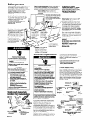
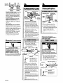
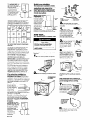
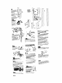
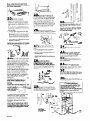
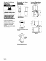
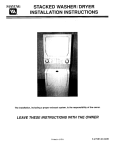
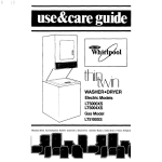
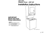
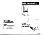
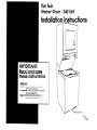
Thin Twin
WasheraDryer - 240 Volt
Installation Instructions
IMPORTANT:
Read and save
.
her IS .
IMPORTANT:
Installer: Leave Installation Instructions
with the homeowner.
Homeowner: Keep Installation Instructic Ins
for future reference.
Save Installation Instructions for local
electrical inspector’s use.
Before you start...
Do Not Store or operate
washer/dryer below 32°F (some
water may remain in washer).
Proper operation of dryer cycles
requires temperatures above 4S’F.
See Use & Care Guide for
“Winterizing” information.
Check code requirements: Some codes limit or
Do Not permit installation of clothes dryers in
garages, closets, mobile homes and sleeping
quarters. Contact your local building inspector.
Check location where washer/dryer will
be installed. Proper installation is your
responsibility. The washer/dryer must not
be installed or stored in an area where it
will be exposed to water and/or
weather, Make sure you have
everything necessary for correct
installation.
Check utilities: Proper water and
electrical supply connections must be
available.
Hot and cold wafer faucets:
Must be within 4 feet of the
back of the washer/dryer
Ond provide water pressure
11) of;-100 PSI.
Locafion: Should be large enough
to fully open dryer door to 90”. See
Panel G for “Recessed and closet
installation instructions” and
“Product dimensions.”
Wafer heater: Set to deliver 140°F
water to the washer.
laundry tub drain system: Needs a
20-gallon laundry tub. Top of tub
must be at least 28 inches high and
no higher than 48 inches from floor.
Grounded electrical outlet is /
required. See “Electrical
requirements. u
If a longer drain hose is needed,
drain hose (Part No. 388423) and
hose extension kit (Part No. 285442)
are available from your authorized
parts distributor.
Standpipe drain system
Needs a two-inch dia
standpipe with minim
carry-away capacity
17 gallons per minute
standpipe must be at least
28 inches high and no higher
than 48 inches from floor.
Dryer may be exhausted from the
rear or left or right side. Exhausting
through the side requires Part No.
279823. See “Exhaust requirements,”
Panels C and D.
Floor drain system requires
a siphon break, Part
No. 285320, availabl
from your authorized
parts distributor.
Four-inch metal exhaust duct is
required.
SEERECESSEDAREA INSTRUCTIONS
ON PANEL G.
w-
Important: Observe all
governing codes and
ordinances.
washer/dryer.
Floor must be
\Supporf:
sturdy enough to
support washer/dryer
weight, with water and
clothes, of 375 pounds.
Electrical reauirements
Electrical Shock Hazard
It is the customer’s responsibility:
To contact a qualified electrical
installer.
To assure that the electrical
installation is adequate.
electrical installation is adequate and in
conformance with the National
Electrical Code, ANSVNFPA 70 - latest
edition*, and all local codes and
ordinances.
Copies oi the standards listed above may be
obtained from:
l National
Fire Protection Association
Batterymarch Park
Quincy, Massachusetts 02269
Failure to do so could result in death
or serious injury.
Electrical Shock Hazard
Electrical ground is required on this
washer/dryer.
Do Not ground to a gas pipe.
Do Not modify the power supply cord
plug. If it will not fit the outlet, have a
proper outlet installed by a qualified
electrician.
Use a new 30-ampere power supply
cord kit. Do Not reuse an old power
supply cord. Possible electrical shock
or fire hazard could occur if old power
supply cord is used.
Do Not have a fuse in the neutral or
grounding circuit. A fuse in the
neutral or grounding circuit could
result in an electrical shock.
Do Not use an extension cord with
this washer/dryer.
Check with a qualified electrician if
you are not sure washer/dryer is
properly grounded.
Fire Hazard
For your safety, the information in
this manual must be followed to
minimize the risk of fire or explosion
or to prevent property damage,
personal injury or loss of life.
- Do Not store or use gasoline or
other flammable vapors and
liquids in the vicinity of this or
any other appliance.
- Never install washer/dryer up
against draperies or curtains or
on carpet.
- Keep any and all items from
falling or collecting behind the
washer/dryer.
- Replace all access panels before
operating washer/dryer.
Failure to follow these instructions
could result in a fire.
Tools and materials
needed for installation:
Failure to follow these instructions
could result in death or serious injury.
Power supply cord
Local codes may permit the use of a U.L.listed, 120/240-volt minimum, 30-ampere,
dryer power supply cord kit (pigtail).
Power supply cord should be Type SRD or
SRDTand be at least four feet long. The
wires that connect to the dryer must end
with ring terminals or spade terminals with
upturned ends. A 3/4”, U.L.-listed strain
relief must be installed where the power
supply cord connects to the dryer (see
Figures 1 and 2).
spade
terminals with
upturned ends
l/4” socket wrench
or nut driver
Panel A
slip-joint pliers
that open to
1- l/2” minimum
A four-wire or three-wire, single-phase,
120/240-volt, 60-Hz AC-only electrical
supply (or four-wire or three-wire,
120/208-volt, if specified on the
model/serial rating plate) is required on
a separate, 30-ampere circuit, fused on
both sides of the line. A time-delay fuse
or circuit breaker is recommended. The
model/serial rating plate is located in
the door well behind the dryer door on
the front of the opening.
It is the personal responsibility and
obligation of the customer to contact a
qualified electrician to assure that the
-
314” U.L.-listed
strain relief
---El\
NEUTRAL
(white)
grounding
prong
terminals
Four-wire
If codes permit and a separate grounding
wire is used, it is recommended that a
qualified electrician determine that the
grounding path is adequate.
duct
tape
-
power supply
cord
NEMA 14-30P
Figure 1
spade
terminals with
upturned ends
IJEIJTRAL -
-
/This
blade connected
to this conductor.
314” U.L.-listed
strain relief
An”
I II my+c.-inn,$
1-1I ,111
IUI
/
NEUTRAL
(white or center)
Three-wire power supply cord
NEMA lo-30P
Figure 2
For use where
local codes
permit use of
flexible power
supply cord.
four-wire
receptacle(l4-30R)
Figure 3
Where local codes permit
connecting cabinetrounding
three-wire
receptacle(lO-30R)
conductor
Figure 4
Four-wire insfallufion is recommended
(required for mobile homes): The power
supply cord must have four, No.-1 0
copper wires and match a four-wire
receptacle of NEMA Type 14-30R (see
Figure 3). The fourth wire (grounding
conductor) must be identified with a
green cover and the neutral conductor
by a white cover.
Three-wire installation (if a four-wire
system is not available): The power
supply cord must have three, No.-1 0
copper wires to match a three-wire
receptacle of NEMA Type 1O-30R (see
Figure 4).
Direct wire
The washer/dryer can be connected
directly to fused disconnect or circuit
breaker box with four-wire or three-wire
flexible armored or non-metallic
sheathed copper cable (with grounding
wire). Do Not use two-wire with bare
grounding wire. All current-carrying
wires must be insulated.
A conduit connector must be installed
at junction box. USEONLY lo-GAUGE
SOLID COPPER WIRE. DO NOT USE
ALUMINUM WIRE. Allow four feet of slack
in the line so dryer can be moved if
servicing is ever necessary.
! A’
m *
Electrical connection
-
Electrical Shock Hazard
Check that wiring you are using
matches colors shown in illustrations
and specified in instruction steps. If
wiring does Not match, it is your
responsibility to have a qualified
electrician install the correct wiring.
Failure to install the correct wiring
could result in death or serious injury.
This washer/dryer Is manufactured wlth the
neutral termlnal connected to the cabinet.
center silver-colored
terminal block screw
\Vf
center silver-colored
terminal block screw
\
I ,appliance
harness
grounding wire
Figure 5
1. Disconnect the power supply.
2. Remove terminal block cover.
3. Install copper, four-wire power
supply cord through strain relief.
4. Remove the appliance harness
grounding wire (green with yellow
stripes) from the internal grounding
connector and fasten under
center, silver-colored terminal block
screw.
5. Connect the grounding wire
(green) of the copper, four-wire
power supply cord to the internal
grounding connector.
6. Connect the neutral wire (white) of
the power supply cord to the
center, silver-colored terminal screw
of the terminal block. Connect the
other wires to the outer terminals.
Tighten screws firmly.
7. Tighten strain relief screws.
8. Replace the terminal block cover. J
appliance
harness
1. Disconnect the power supply.
2. Remove terminal block cover.
3. Install copper three-wire power
supply cord through strain relief.
4. Connect the neutral wire (white or
center) of the power supply cord to
the center, silver-colored terminal
screw of the terminal block.
Connect the other wires to the
outer terminals. Tighten screws
firmly.
5. Tighten strain relief screws.
6. Replace the terminal block cover.
Where local codes permit
connecting cabinet- rounding
conductor to the neu 3ral wire of the
power supply cable:
.-.-.
..........
,:,:.:
:.:,>
.....
,:,:,:
:;::)
22.
4
..-.-.-.-:.-.
..-.-.-.-.-...~
$$ 1. Disconnect the power supply.
$$ 2. Remove terminal block cover.
$3; 3. Strip 5 inches of outer covering from
:::::::::::
::::::::::: end of cable. Leave bare
.:::p,:::
:::::::::::
:::::::::::
grounding wire at 5 inches. Cut
:::::::::::
;i;i;;i;;$
1-l /2 inches from 3 remaining
:~~~~~~::‘:
,:.:.:.:.:.
:::::::+ insulated wires. Strip insulation back
:.:p-:.,
ig:i:s.:: 1 inch (see Figure 6).
i ...
$$$$j~
1. Disconnect the power supply.
3/4” U.L.-listed
strain relief,
;:j:j:j:j:j:j:j:
.. ..--
wires
stritmed
insihtion
of
.:,:.:.:,:,:,>:
Electrical Shock Hazard
:;::::::x:::::
::::::::::::::::
f$J$$
Do
Not
use
two-wire with a bare
/I
:::::<:::ij
grounding
wire.
All current-carrying
.-::..:.
_.:
:::;:::;g::
::::::::::::::::
wires
must
be
insulated.
:;:;:::;:;:g;:;
:zz$ Failure to install the correct wiring
@ could result in death or serious injury.
:::::::::::::::,
ig;;;iijijig
~iiltiii;::2. Remove terminal block cover.
$$$$ 3. Strip
3-l/2 inchesofoutercovering
from
end of cable. If using three:::::;:::::::::
::::::::::::::::
:;:i:;:;:;:;:;:i
wire
cable
with grounding wire, cut
::::::::::::::::
::::::::::::::::
the
bare
wire
even with outer
::::::::::::::::
::::::::::::::::
::::::::::::::::
covering.
Strip
1 inch of insulation
~:::~:~~~:~~:~:’
::::::::::::>>
::::::::y$:
.A..
..,_,.,,,.from the end of each insulated wire
:::::::<:::;:~I.
Direct wire preparation
Figure 6
u-shaped
hook
Figure 7
\1
Shape the end of
each wire into a ‘U”
shaped hook (see
Figure 7). The bare
grounding wire must
be 4-l /2” long after
forming the hook.
4. Install copper, four-wire power
supply cable through strain relief.
5. Remove the appliance harness
grounding wire (green with yellow
stripes) from the internal grounding
connector and fasten under center,
silver-colored terminal block screw.
6. Slide the hook end of the grounding
wire (bare) of the four-wire power
supply cable under the internal
grounding connector screw.
Squeeze hook end of wire together.
Tighten screw.
7. Connect the neutral wire (white) of
the power supply cable to the
center, silver-colored terminal screw
of the terminal block using the same
method. Connect the other wires to
the outer terminals. Tighten screws
firmly.
8. Tighten strain relief screws.
9. Replace the terminal block cover.
Panel B
to the neu 3ral wire:
(seeFigure
9).
314” U.L.-listed
strain relief ,
Bare wire cut short. Wire is not
used. Dryer is grounded
through direct wire cable.
_
I
I
Direct wire preparation
Figure 9
;J$;Ped
Figure 10
Shape the end of
each wire into a
‘U” shaped hook
(see Figure 10).
Exhaust requirements
center silver-colored
block screw
\
terminal
neutral
(white 01
center)
Efl,appliance
3Y/ e] St@+)
cabinet---...-.
grounding
connector
Figure 11
4. Install copper, three-wire power
supply cable through strain relief.
5. Slide the hook end of the neutral
(white or center) wire from the
three-wire power supply cable
under the center, silver-colored
terminal screw of the terminal block.
Squeeze the hook end of the wire
together. Tighten screw.
6. Connect the other wires to the outer
terminals using the same method.
Tighten screws firmly (see Figure 11).
7. Tighten strain relief screws.
8. Replace the terminal block cover.
Where local codes DO NOT permit
connecting the cabinet-grounding
conductor to the neutral (white)
wire:
center silvercolored terminal
block screw,
Tighten clamp
securely to pipe.
external
cabinetgrounding
connector
n
f ’ fI
AL
harness
grounding
appliance harness
grounding wire (green
with y?llow stripes)
I
r
Bumps on ground
strap must contact
Pipe.
Figure 13
Use grounding wire and clamp
assembly (Part No. 685463) or No.-10
gauge minimum copper grounding
wire.
cold
metal
I-I- clamps
‘-I
Figure 14
Connect grounding wire to a
grounded cold water pipe* with the
clamp and then to the external
grounding connector on the
washer/dryer (see Figures 13 and 14).
Do not ground to a gas supply pipe or
hot water pipe. Do not connect the
power supply cord to electrical power
supply until the washer/dryer is
permanently grounded.
* Grounded
cold water pipe must have
metal continuity to electrical ground
and not be interrupted
by plastic, rubber
or other electrical insulating connectors
such as hoses, fittings, washers or gaskets
(including water meter or pump). Any
electrical
insulating connector
should be
jumped as shown in Figure 14 with a
length of No.-4 wire securely clamped
to
bare metal at both ends.
Fire Hazard
Do Not use non-metal, flexible duct.
Do Not use metal duct smaller than
4 inches in diameter.
Do Not use exhaust hoods with
magnetic latches.
Check that exhaust system is not
longer than specified. Exhaust
systems longer than specified will:
-Accumulate
lint.
-Shorten the life of the product.
-Reduce performance and result in
longer drying times and increased
energy usage.
Failure to follow these instructions
could result in a fire.
Do Not exhaust the dryer into a
chimney, furnace cold air duct, attic
or crawl space, or any other duct
used for venting.
Clean the exhaust system every year.
Do Not install flexible duct in walls,
ceiling or floors.
Accumulated lint could cause a fire
or moisture damage.
Exhausting your dryer indoors is Not
recommended. The moisture and lint
indoors may cause:
-Lint to gather inside and around
the dryer and could cause a fire.
-Moisture
damage to woodwork,
furniture, paint, wallpaper, carpet,
etc.
-Housecleaning
problems and
possible health problems.
Failure to follow these instructions
could result in fire damage, personal
injury or health problems.
Connect separate copper grounding wire from
external grounding connector to approved
ground.
Figure 12
1. Disconnect fhe power supply.
2. Remove terminal block cover.
3. Install solid copper, power supply
cord or cable through strain relief.
4. Remove the appliance harness
grounding wire (green with yellow
stripes) from the internal grounding
connector.
5. Connect the grounding wire (green
with yellow stripes) and the neutral
(white) wire of the power supply
cord or direct wire cable to the
center, silver-colored terminal screw
of the terminal block. Connect the
other wires to the outer terminals.
Tighten screws (see Figure 12).
6. Connect a separate copper
grounding wire (No.-1 0 minimum).
See “Connection details” for
detailed instructions.
7. Tighten strain relief screws.
8. Replace the terminal block cover.
Panel C
If using an existing exhaust system,
clean lint from entire length of exhaust
system. Make sure exhaust hood is not
plugged wifh lint.
The exhaust system should be inspected
and cleaned yearly.
Replace any vinyl or metallized plastic
foil exhaust duct with rigid metal or
flexible metal duct.
Use duct tape to seal
all joints. Do Not use
screws to secure duct.
exhaust air flow
better
d
Four-inch rigid metal pipe is preferred.
Plan installation to use the fewest
number of elbows and turns.
Metal flexible duct should be fully
extended and supported when the
dryer is in its final position. DO NOT KINK
OR CRUSH THE DUCT. The metal flexible
duct must be fully extended to allow
adequate exhaust air to flow.
Allow as much room as possible when
using elbows or making turns. Bend duct
gradually to avoid kinking. Remove
excess flexible duct to avoid sagging
and kinking that may result in reduced
air flow.
The exhaust duct can
be routed up, down,
left, right or straight out
the back of the
washer/dryer. Space
requirements are
provided on Panel G
and on the rear panel
of the washer/dryer.
Use the straightest
b
path you can to
avoid 90” turns.
’
Mobile home installation
This washer/dryer is suitable for mobile
home installations. The installation of the
washer/dryer must conform to the
Manufactured Home Construction and
Safety, Title 24 CFR, Part 3280 (formerly
the Federal Standard for Mobile Homes
Construction and Safety, Tile 24. HUD
Part 280, latest edition).
Maximum length of the exhaust system
depends upon the type of duct used,
number of elbows and the type of
exhaust hood. The maximum length for
both rigid and flexible duct is shown in
the chart.
rigid
metalduct
18ft
I
18ft
Mobile home exhaust
requirements: The
washer/dryer must
-outside
have an outside
wall
exhaust. If the dryer is
exhausted through
the floor and the
area under the
mobile home is
enclosed, the
exhaust system
skirting
must terminate
outside the
enclosed area. tloor enclosed area
Extension beyond the enclosure will
prevent lint and moisture buildup under
the mobile home.
Now start...
not
I recommende
with washer/dryer
in laundry area.
flexible
rear
l 4 legs
* 1 drain hose clamp
l 1 plastic
beaded
strap
l
l
4 flat, waterhose washers
1 small clamp
3
n Remove parts from plastic
package. Check that all parts were
included.
4
n Insert a rearleveling leg into the hole
in the rear corner on the
bottom of the
washer/dryer. Push leg in
until it snaps into place.
Do the same same thing
with the other leveling
leg in the other rear corner.
metalduct
IOfl
9ft
not
recommende
The maximum length usin a 2” x 6’ rectan ular
duct with 2 elbows and a s -l/2” (TYPEC) ex7l aust
hood is 8 tt.
For exhaust configurations other than
those listed in the chart, the back
pressure MUST not exceed 0.2 inches
water column at the back of the
washer/dryer. The back pressure should
be checked by a qualified technician.
For exhaust systems not covered by the
exhaust length chart, see Service
Manual, Part No. 603197, available from
your authorized parts distributor.
Service check: The back pressure in any
exhaust system used must not exceed
0.2 inches of water column measured
with an inclined manometer at the
point that the exhaust duct connects to
the dryer.
Exhausting the dryer outside is
recommended.
Recessed installation
that is not exhausted outside must use
Exhaust Deflector Kit Part No. 694609,
available from your authorized parts
distributor. See “Recessed and closet
installation instructions,” Panel G, for
unobstructed air opening requirements,
If the washer/dryer is installed in a
confined area such as a bedroom,
bathroom or closet, it must be
exhausted to the outside and provision
must be made for enough air for
ventilation. Check governing codes and
ordinances. Also refer to the “Recessed
and closet installation instructions” on
Panel G.
An exhaust hood
should cap the
exhaust duct to
prevent exhausted
air from returning
12”
into dryer. The
mlnlmum
35
outlet of the
hood must be at least 12 inches from
the ground or any object that may be in
the path of the exhaust.
Four-inch exhaust hood is preferred.
However, a 2-l/2-inch exhaust hood
may be used. A 2-l/2-inch exhaust
hood creates greater back pressure
than other hood types. For permanent
installation, a stationary exhaust system
is required.
Exhausting the dryer
through the side of the
washer/dryer requires
m-l
the use of Side Exhaust
Kit, Part No. 279823,
available from your
authorized parts
distributor. Follow kit
Installation
Instructions for
proper exhaust
installation.
Panel D
Injury Hazard
More than one person is required to
lift, tilt or move the washer/dryer
because of its weight and size.
Failure to follow this instruction
result in injury.
may
n Push up one leg;
check to see that the
other leg goes down.
Check the other leg
the same way. (If legs
do not adjust, repeat
Step 4.)
6
Truck only from rear to prevent product
damage.
1
n
Put on safety glasses and gloves.
2
n
Remove shipping cardboard
base.
Numbers
correspond
to steps.
n With one of the front
legs in hand, check the
ridges for a diamond
marking. That’s how far the
leg is supposed to go into
the hole. Start to screw the
legs into the holes in the
front corners by hand.
Use slip-joint pliers to finish turning the
front legs until you reach the diamond
mark.
Slide washer/dryer onto cardboard or
hardboard before moving across floor to
prevent damage to floor covering.
7
n Place a piece
of cardboard or
hardboard in front of
carton. Now stand the
washer/dryer upright.
Slide washer/dryer
onto cardboard
To orevent oroduct
dahage, do not
remove corner
posts inside the
carton before
cutting.
-v
With the corner posts in place,
8
cut the carton down one corner.
n
Remove carton.
Do Not
Remove
9
n Remove
the two rear corner
posts located at the
back of the
washer/dryer*
Remove the two
corner pieces
attached to the lower
front of the
washer/dryer. DO Not
remove the foam
shipping pieces
between the washer
and dryer until the
washer/dryer is in place,
Numbers
CarreSDOnd
rear
comer
posts
to steljs.
I
10
n Move
foam shipping
pieces outward
just enough to
clear the washer
lid. Open the
washer lid. The
latch under the
dryer will hold lid open.
Pull
ig$&
p
. .
-- .-;
shipptng straps.
Slide washer/dryer onto cardboard or
hardboard before moving across floor to
ovoid damaging floor covering.
v
3 shippingstraps
11.
I m iRead
the yellow
card. Place hand on top Of
agitator when removing
the shipping straps. Firmly
jerk, then pull the three
shipping straps up until
each strap with key is
completely removed from
washer. Put straps in the same
area as other shipping pieces.
1”1
19
-w
16
m Attach hose to bottom (hot
water) inlet valve opening first; then
second hose to top (cold water) inlet
valve. Tighten couplings by hand. Use
pliers to make an additional two-thirds
turn.
IMPORTANT: THIS PROCEDURE
MUST BE FOLLOWEDTO ASSURE
PROPERINSTALLATION.
12
8 Remove
yellow card. Take
hoses out of basket.
Place hoses with
other parts.
/
clamp
m It you have room to work from
either
side of the washer/dryer! move
4
washer/dryer close to final posltlon SO
Lv\
you
YO can easily complete the following
srep 20.)
zu.)
steps. (Go to Step
If yiu are working in a closet or
recessed area, move the washer/dryer
into final position and remove
cardboard/hardboard
from under
washer/dryer, Remove the two foam
shipping pieces between the washer
and dryer and place with the other
shipping pieces. Remove the two
Phillips-head screws located at the top
of the access panel. (.%?eillustration for
Step 25.) Remove access panel and set
access panel and screws aside.
Complete the following steps through
the access area.
20
l Put nhook” end of drain hose
into laundry tub or standpipe. Check for
proper length of drain hose.
connector
17
13
n Release washer lid
by pushing up on latch. Close lid,
14
m Disconnect the power supply.
Connect power supply cord or cable to
dryer. See “Electrical connection, *
Panels B and C, Do Not plug power
supply cord into outlet or reconnect
power at this time.
Use new hoses and washers that came
with your washer/dryer.
15
I
coupling
I
washer
l Insert a flat washer into each
end of the inlet hoses. Check that
washers are firmly seated in couplings.
Panel E
mTo prevent the drain hose
from coming ‘off or leaking, it must be
installed per the following instructlons:
1, Wet the inside end of the drain hose
with tap water. DO NOT USEANY
OTHERLUBRICANT.
2. Squeeze ears of drain hose clamp
with pliers to open and place Clamp
over the end of the drain hose.
3. While holding clamp open, work end
of drain hose onto drain connector
4. Position clamp over the drain hose
area marked “clamp. n Release
clamp. Clamp should be l/4 Inch
from end of drain hose.
3Q
_.
18 n Standpipe
or
laundry
tub drain system:
Ic
Open
yellow clamp and
C
slide
over “hook” end of
Sl
drain hose to secure the
rigid and corrugated
sections together.
Floor drain system: Do
Not install “hook” end of drain hose t0
corrugated section, Consult your
plumber for proper installation.
l Before attaching water inlet
hoses, run water through both faucets
into
in a bucket. This will get rid of particles
in water lines that might clog hoses.
Mark whicn
which IS
is Tne
the not
hot WaTer
water TUUC;GI.
faucet.
i7
i GM Attach bottom inlet hose
(inlet marked ‘H”) to hot water faucet;,
Attach top inlet hose (inlet marked UC )
to cold water faucet. Tighten couplings
to the faucets by hand, Use pliers to
make final two-thirds turn.
Move washer/dryer to its permanent
location. Remove cardboard/hardboard
from under washer/dryer.
23
n Carefullv move the
washer/dryer into final position.
Tilt the washer/dryer forward, raising
back legs 1 inch off the floor so that
the rear self-leveling legs will adjust.
Gently lower the washer/dryer to the
floor.
Check that the washer/dryer is level
by placing a carpenter’s level on top
of the washer, first side to side. then
front to back.
- If it is not level, adjust the front legs
up or down.
- Tilt the washer/dryer forward, raising
back legs 1 inch off the floor so that
the rear self-leveling legs will adjust.
Gently lower the washer/dryer to the
floor.
- Check that the washer/dryer is level.
Repeat as needed.
l
l
access panel in Step 19, remove the
two foam shipping pieces between the
washer and dryer and place with the
other shipping pieces. If the exhaust
duct cannot be connected from the
side of the washer/dryer, the exhaust
duct can be reached from the front
through the access panel. Remove the
two Phillips-head screws located at the
top of the access panel. Set access
panel and screws aside.
30
w Check that you
removed all the shipping pieces,
including the three shipping straps with
keys. Dispose of all materials in proper
manner,
If you do not remove all three shipping
straps, your washer/dryer may “walk”
away from its location.
26
n Determine the length of
exhaust duct that is needed to connect
the dryer to the exhaust hood. (See
“Exhaust requirements,” Panels C and D,)
CHECK THAT DRAIN HOSE IS NOT TWISTED
OR KINKED AND IS SECURELYIN PLACE.
27
n Connect exhaust duct to
washer/dryer and then to the exhaust
hood.
Use the straightest path possible to
avoid 90” turns.
Use duct tape to seal all joints in the
exhaust system.
Use caulking compound to seal
exterior wall opening around exhaust
hood.
31
n
Check that you have all of
your tools.
l
32
WTurn on water faucets and
check for leaks. Tighten couplings if
there is leaking. Do Not overtighten; this
could cause damage to faucets.
l
strap
baded
24
A
A
nl,
,.ostic beaded strap
Put “hook” end of drain hose
in laundry tub or standpipe. Wrap the
plastic beaded strap around the drain
hose and laundry tub or standpipe.
Thread beaded end of strap through
keyhole end. Pull until strap is tight. Slide
strap into narrow end of keyhole to lock
strap in place. See Figures A-B.
If the water inlet faucets and drain
standpipe are recessed, tightly wrap the
plastic beaded strap around the drain
hose and faucet body. (Do Not wrap
strap around the faucet handles or
stems,) Thread beaded end of strap
through keyhole end. Pull until strap is
tight. Slide strap into narrow end of
keyhole to lock strap in place.
See Figure C.
D
Secure the drain hose to the tub
or standpipe with the plastic
strap. Failure to properly secure
drain hose could result in water
damage.
l
33
n Replace access panel. Be
sure to tighten screws at each end of
the access panel.
n
If drain hose cannot be strapped
into place, hose must be cut
exactly to length so
“hook” end is held
tightly over edge of
tub or standpipe.
Figure D.
PI
28
w CHECK ELECTRICAL
REQUIREMENTS.BE SUREYOU HAVE
CORRECTELECTRICALSUPPLYAND
RECOMMENDED GROUNDING METHOD.
Check the Installation Instructions to see
that you have completed each step.
Complete any missed steps before you
continue.
34
tread the Use and Care
Guide to fully understand your new
washer/dryer. Open dryer door. Check
to be sure lint screen is in its proper
position. Wipe out drum.
35
n Plug power supply cord into
grounded outlet. Reconnect the power
supply. Now start the washer and allow
it to complete the regular cycle.
36
n Start dryer and allow it to
comblete a full heat cycle to make sure
it is working properly. ’
Congratulations!
You have successfully installed your
new washer/dryer. To get the most
efficient use from your new
washer/dryer, read your Use and Care
Guide.
Keep Installation Instructions and
Guide.
29
n Check that all parts are now
installed. See parts list, Panel D. If there is
an extra part, go back through steps to
see which step was skipped.
If a longer drain hose is needed, drain
hose (Part No. 388423) and hose
extension kit (Part No. 285442) are
available from your authorized parts
distributor. If drain hose must be
shortened, use hose kit (Part No.
285442).
Note: If washer/dryer is moved to adjust
drain hose, the washer/dryer must be
leveled again. Repeat Step 23. Place
cardboard under the washer/dryer and
carefully move washer/dryer to avoid
damaging floor covering.
Numbers
correwond
to steljs.
Panel F
I
’
#
18.
\>
Recessed and closet
installation
instructions
Product dimensions
Recessed and closet
:nstalIation
nstructfons
(Shown wlth legs extended
bottom ot washer/dryer.)
L-1
24"
Recessed installation
12'
r*
.
--I
3” j
c
Fire Hazard
It is recommended that the
washer/dryer be exhausted to the
outside.
If washer/dryer is installed in a closet,
the dryer MUST be exhausted outside.
Failure to do so may result in a fire.
*
TO PREVENTLARGE AMOUNTS OF LINT
AND MOISTUREFROM ACCUMULATING,
TO MAINTAIN DRYING EFFICIENCY AND
TO PREVENTEXPOSURETO POSSIBLE
HEALTHHAZARDS, THIS WASHER/DRYER
SHOULD BE EXHAUSTEDOUTDOORS.
f ront view
side view
Mlnlmum lnstallatlon spacing
Note: If recessed installation is exhausted, all
spacing can be 0 in.
Additional clearance for wall, door and floor
molding may be required.
rear view
This washer/dryer may be installed in a
recessed area or closet.
The installation spacing is in inches and
is minimum allowable. Additional
spacing should be considered for ease
of installation, servicing and compliance
with local codes and ordinances.
If closet door is installed, the minimum
unobstructed air openings in top and
bottom are required. Louvered doors
with equivalent air openings are
acceptable. C I
exhausted.
Other installations must use the minimum
dimensions indicated.
Closet installation
closet door
I
front view
Unobstructed air openings are minimum for closet
door. louvered door with equivalent air openings
is acceptable.
+27-1/C'+
side view
1 Additional
24
i-
sq. In.
ic i-l
-4 k
‘”
side view
Closet installation must be exhausted outdoors.
Recessed, non-exhausted installation must use
only the rear exhaust position and Exhaust
Deflector Kit No. 4500 Is required.
Panel G
1 Inch from
If washer/dryer
not operate.,
does
Check the following to be sure that:
1. Electrical supply is connected.
2. House fuse or circuit breaker is intact
and tight.
3. Washer lid or dryer door is closed,
4. Controls are set in a running or “ON”
position.
5. Dryer start button has been firmly
pushed.
6. Three shipping straps have been
completely removed.
Part No. 3397612
01995
When moving the
washer/dryer.. .
l
l
l
l
Disconnect the power supply cord,
then tape securely to the
washer/dryer.
Tape the drum to the front panel.
Tape the lint screen in place. Tape
the dryer door closed.
Wedge a blanket between the
laundry tub ring and cabinet top to
restrict tub movement.
Turn front leveling legs all the way in.
Benton Harbor, Michigan 49022
If you need assistance...
Check your Use and Care Guide for a tollfree number to call, or call the dealer from
whom you purchased this appliance. The
dealer is listed in the Yellow Pages of your
phone directory under “Appliances Household - Major - Service and Repair.”
When you call, you will need the
washer/dryer model number and serial
number. Both numbers can be found on
the model/serial rating plate located
behind the dryer door on the dryer door
well.
Printed in U.S.A.