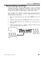
1
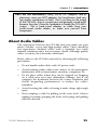
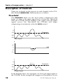
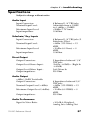
Compressor / Limiter / Expander
Reference
Manual
2001
CLX-440 Reference Manual
1
CLX-440 Manual
2
CLX-440 Reference Manual
CLX-440 Manual
Contents
Contents........................................................................................................................3
Welcome!.....................................................................................................6
How to Use This Manual .........................................................................7
Important Safety Instructions..................................................................8
CE Declaration of Conformity...............................................................10
Instructions to the User (FCC Notice)..................................................14
Quick Start Guide .....................................................................................................15
If you can't wait to get started:..............................................................15
Step 1: Hook it up to a mixer ........................................................15
Step 2: Try some compression ......................................................16
Step 3: Try some gating..................................................................17
Connections...............................................................................................................19
Unpacking and Inspection.....................................................................19
Installing in a Rack ..................................................................................19
Power .........................................................................................................20
Connecting inputs and outputs ............................................................22
Connecting to the Channel Inserts of a mixing console: .........22
Connecting to the Main Inserts of a mixing console: ...............23
Connecting to the inserts on an instrument amplifier: ............24
Connecting to equipment with XLR inputs and outputs:.......24
About Audio Cables................................................................................25
Dual Channel Operation ........................................................................26
Basics of Compression............................................................................................27
What is compression? .............................................................................27
Description of Controls ..........................................................................28
Threshold .......................................................................................28
Ratio ................................................................................................29
Attack..............................................................................................29
Release ............................................................................................29
Detect ..............................................................................................29
Knee ................................................................................................30
Compression Artifiacts...........................................................................31
Pumping and Breathing ..............................................................31
Clicking or "Zipper Noise" .........................................................31
Reduced Gain Structure ..............................................................31
CLX-440 Reference Manual
3
CLX-440 Manual
Limiting .....................................................................................................32
Limiter Threshold.........................................................................32
Stereo Detection .......................................................................................33
Look Ahead Compression .....................................................................33
Sidechain ...................................................................................................34
Basics of Expansion.................................................................................................35
What is expansion?..................................................................................35
Description of Controls ..........................................................................36
Threshold .......................................................................................36
Ratio ................................................................................................36
Knee ................................................................................................37
Attack..............................................................................................37
Hold ................................................................................................37
Release ............................................................................................38
Keyed Expansion .....................................................................................39
Applications...............................................................................................................41
Compressor Applications ......................................................................41
Vocal Limiting...............................................................................41
Vocal Compression ......................................................................42
Drums .............................................................................................42
Bass..................................................................................................43
Electric Guitar ...............................................................................43
Compressor Applications using the Sidechain..................................44
De-essing........................................................................................44
Ducking ..........................................................................................45
Expander Applications...........................................................................46
Gating a Noisy Guitar Amp .......................................................46
Expanding Live Vocal Tracks ....................................................46
Expander Applications using the Key.................................................47
Gated Reverb.................................................................................47
Key Filtering for a Tom Mic gate...............................................48
Staccato Gating a Synth Pad.......................................................49
Troubleshooting.......................................................................................................51
Troubleshooting Index ...........................................................................51
Avoiding ground loop noise ......................................................52
Line Conditioners and Protectors .............................................53
Care and Maintenance............................................................................54
Cleaning .........................................................................................54
Refer All Servicing to Alesis.......................................................54
Obtaining Repair Service ............................................................55
Specifications............................................................................................57
4
CLX-440 Reference Manual
CLX-440 Manual
Audio Input .................................................................................57
Sidechain/ Key Inputs...............................................................57
Direct Output...............................................................................57
Audio Output ..............................................................................57
Audio Performance ....................................................................57
Mechanical ...................................................................................58
Alesis Limited Warranty.........................................................................................59
CLX-440 Reference Manual
5
CLX-440 Manual
Welcome!
Thank you for making the Alesis CLX-440™ a part of your
studio. Since 1984, we've been designing and building creative
tools for the audio community. We believe in our products,
because we've heard the results that creative people like you
have achieved with them. One of Alesis' goals is to make highquality studio equipment available to everyone, and this
Reference Manual is an important part of that. After all, there's
no point in making equipment with all kinds of capabilities if no
one explains how to use them. So, we try to write our manuals
as carefully as we build our products.
The goal of this manual is to get you the information you need as
quickly as possible, with a minimum of hassle. We hope we've
achieved that. If not, please drop us an email and give us your
suggestions on how we could improve future editions of this
manual.
We hope your investment will bring you many years of creative
enjoyment and help you achieve your goals.
Sincerely,
The people of Alesis Studio Electronics
6
CLX-440 Reference Manual
CLX-440 Manual
How to Use This Manual
This manual is divided into the following sections describing the
various functions and applications for the CLX-440. While it's a
good idea to read through the entire manual once carefully,
those having general knowledge about studio equipment should
use the table of contents to look up specific functions.
Chapter 1: Quick Start. If you're already familiar with
recording, this will get you started using the CLX-440 right
away. It's a short guide to the essential elements of connections
and operation.
Chapter 2: Connections. This section gives detailed instructions
for connecting the CLX-440 to a variety of typical audio systems.
Chapter 3: Basics of Compression. This section explains what a
compressor does and explains the function of each of the
controls.
Chapter 4: Basics of Expansion. This chapter explains the other
major feature of the CLX-440, expansion, and each of the front
panel controls dedicated to this function.
Chapter 5: Applications. Skip to this section for tips on using the
CLX-440 with a variety of audio sources.
Chapter 6: Troubleshooting. Refer to this chapter if you
experience any problems while using the CLX-440.
Helpful tips and advice are highlighted in a shaded box like this.
The names of specific controls or connectors on the CLX-440 are
printed in a special font, i.e., the BYPASS button.
✪
When something important appears in the manual, an icon
(like the one on the left) will appear in the left margin. This
symbol indicates that this information is vital when operating
the CLX-440.
CLX-440 Reference Manual
7
CLX-440 Manual
Important Safety Instructions
Safety symbols used in this product:
This symbol alerts the user that there are important
operating and maintenance instructions in the literature
accompanying this unit.
This symbol warns the user of uninsulated voltage within
the unit that can cause dangerous electric shocks.
This symbol warns the user that output connectors contain
voltages that can cause dangerous electrical shock.
Please follow these precautions when using this
product:
1. Read these instructions.
2.
Keep these instructions.
3.
Heed all warnings.
4.
Follow all instructions.
5.
Do not use this apparatus near water.
6.
Clean only with a damp cloth. Do not spray any liquid cleaner
onto the faceplate, as this may damage the front panel controls
or cause a dangerous condition.
7.
Install in accordance with the manufacturer's instructions.
8.
Do not install near any heat sources such as radiators, heat
registers, stoves, or other apparatus (including amplifiers) that
produce heat.
9. Do not defeat the safety purpose of the polarized or groundingtype plug. A polarized plug has two blades with one wider than
the other. A grounding-type plug has two blades and a third
grounding prong. The wide blade or the third prong are
provided for your safety. When the provided plug does not fit
8
CLX-440 Reference Manual
CLX-440 Manual
into your outlet, consult an electrician for replacement of the
obsolete outlet.
10. Protect the power cord from being walked on or pinched,
particularly at plugs, convenience receptacles, and the point
where they exit from the apparatus.
11. Use only attachments or accessories specified by the
manufacturer.
12. Use only with a cart, stand, bracket, or table designed for use
with professional audio or music equipment. In any installation,
make sure that injury or damage will not result from cables
pulling on the apparatus and its mounting. If a cart is used, use
caution when moving the cart/apparatus combination to avoid
injury from tip-over.
13. Unplug this apparatus during lightning storms or when unused
for long periods of time.
14. Refer all servicing to qualified service personnel. Servicing
is required when the apparatus has been damaged in any way,
such as when the power-supply cord or plug is damaged, liquid
has been spilled or objects have fallen into the apparatus, the
apparatus has been exposed to rain or moisture, does not
operate normally, or has been dropped.
15. This unit produces heat when operated normally. Operate in a
well-ventilated area with at least six inches of clearance from
peripheral equipment.
16. This product, in combination with an amplifier and headphones
or speakers, may be capable of producing sound levels that
could cause permanent hearing loss. Do not operate for a long
period of time at a high volume level or at a level that is
uncomfortable. If you experience any hearing loss or ringing in
the ears, you should consult an audiologist.
17. Do not expose the apparatus to dripping or splashing. Do not
place objects filled with liquids (flower vases, softdrink cans,
coffee cups) on the apparatus.
18. WARNING: To reduce the risk of fire or electric shock, do not
expose this apparatus to rain or moisture.
CLX-440 Reference Manual
9
CLX-440 Manual
Instructions de Sécurité Importantes (French)
Symboles utilisés dans ce produit
Ce symbole alèrte l’utilisateur qu’il existe des instructions de
fonctionnement et de maintenance dans la documentation jointe avec
ce produit.
Ce symbole avertit l’utilisateur de la présence d’une tension
non isolée à l’intérieur de l’appareil pouvant engendrer des chocs
électriques.
Ce symbole prévient l'utilisateur de la présence de tensions
sur les
raccordements de sorties, représentant un risque
d'électrocution.
Veuillez suivre ces précautions lors de l’utilisation de l’appareil:
1. Lisez ces instructions.
2.
Gardez ces instructions.
3.
Tenez compte de tous les avertissements.
4.
Suivez toutes les instructions.
5.
N’utilisez pas cet allareil à proximité de l’eau.
6.
Ne nettoyez qu’avec un chiffon humide. Il est potentiellement
dangereux d'utiliser des pulvérisateurs ou nettoyants liquides
sur cet appareil.
7.
Installez selon les recommandations du constructeur.
8.
Ne pas installer à proximilé de sources de chaleur comme
radiateurs, cuisinière o u autre appareils (don’t les
amplificateurs) produisant de la chaleur.
9. Ne pas enlever la prise de terre du cordon secteur. Une prise
murale avec terre deux broches et une troisièrme reliée à la terre.
Cette dernière est présente pour votre sécurité. Si le cordon
secteur ne rentre pas dans la prise de courant, demandez à un
électricien qualifié de remplacer la prise.
10
CLX-440 Reference Manual
CLX-440 Manual
10. Evitez de marcher sur le cordon secteur ou de le pincer, en
particulier au niveau de la prise, et aux endroits où il sor de
l’appareil.
11. N’utilisez que des accessoires spécifiés par le constructeur.
12. N’utilisez qu’avec un stand, ou table conçus pour l’utilisation
d’audio professionnel ou instruments de musique. Dans toute
installation, veillez de ne rien endommager à cause de câbles qui
tirent sur des appareils et leur support.
13. Débranchez l’appareil lors d’un orage ou lorsqu’il n’est pas
utilisé pendant longtemps.
14. Faites réparer par un personnel qualifié. Une réparation est
nécessaire lorsque l’appareil a été endommagé de quelque sorte
que ce soit, par exemple losrque le cordon secteur ou la prise
sont endommagés, si du liquide a coulé ou des objets se sont
introduits dans l’appareil, si celui-ci a été exposé à la pluie ou à
l’humidité, ne fonctionne pas normalement ou est tombé.
15. Puisque son fonctionement normale génère de la chaleur, placez
cet appareil au moins 15cm. des équipments péripheriques et
assurez que l’emplacement permet la circulation de l’air.
16. Ce produit, utilisé avec un amplificateur et un casque ou des
enceintes, est capable de produite des niveaux sonores pouvant
engendrer une perte permanente de l’ouïe. Ne l’utilisez pas
pendant longtemps à un niveau sonore élevé ou à un niveau non
confortable. Si vous remarquez une perte de l’ouïe ou un
bourdonnement dans les oreilles, consultez un spécialiste.
Beim Benutzen dieses Produktes beachten Sie bitte
die folgenden Sicherheitshinweise: (German)
1. Lesen Sie die Hinweise.
2.
Halten Sie sich an die Anleitung.
3.
Beachten Sie alle Warnungen.
4.
Beachten Sie alle Hinweise.
5.
Bringen Sie das Gerät nie mit Wasser in Berührung.
CLX-440 Reference Manual
11
CLX-440 Manual
6.
Verwenden Sie zur Reinigung nur ein weiches Tuch. Verwenden
Sie keine flüssigen Reinigungsmittel. Dies kann gefährliche
Folgen haben.
7.
Halten Sie sich beim Aufbau des Gerätes an die Angaben des
Herstellers.
8.
Stellen Sie das Gerät nich in der Nähe von Heizkörpern,
Heizungsklappen oder anderen Wärmequellen (einschließlich
Verstärkern) auf.
9.
Verlegen Sie das Netzkabel des Gerätes niemals so, daß man
darüber stolpern kann oder daß es gequetscht wird.
10. Benutzen Sie nur das vom Hersteller empfohlene Zubehör.
11. Verwenden Sie ausschließlich Wagen, Ständer, oder Tische, die
speziell für professionelle Audio- und Musikinstrumente
geeignet sind. Achten Sie immer darauf, daß die jeweiligen
Geräte sicher installiert sind, um Schäden und Verletzungen zu
vermeiden. Wenn Sie einen Rollwagen benutzen, achten Sie
darauf, das dieser nicht umkippt, um Verletzungen
auszuschließen.
12. Ziehen Sie während eines Gewitters oder wenn Sie das Gerät
über einen längeren Zeitraum nicht benutzen den Netzstecher
aus der Steckdose.
13. Die Wartung sollte nur durch qualifiziertes Fachpersonal
erfolgen. Die Wartung wird notwendig, wenn das Gerät
beschädigt wurde oder aber das Stromkabel oder der Stecker,
Gegenstände oder Flüssigkeit in das Gerät gelangt sind, das
Gerät dem Regen oder Feuchtigkeit ausgesetzt war und deshalb
nicht mehr normal arbeitet oder heruntergefallen ist.
14. Dieses Gerät produziert auch im normalen Betrieb Wärme.
Achten Sie deshalb auf ausreichende Lüftung mit mindestens 15
cm Abstand von anderen Geräten.
15. Dieses Produkt kann in Verbindung mit einem Verstärker und
Kopfhörern oder Lautsprechern Lautstärkepegel erzeugen, die
anhaltende Gehörschäden verursachen. Betreiben Sie es nicht
über längere Zeit mit hoher Lautstärke oder einem Pegel, der
Ihnen unangenehm is. Wenn Sie ein Nachlassen des Gehörs
oder ein Klingeln in den Ohren feststellen, sollten Sie einen
Ohrenarzt aufsuchen.
12
CLX-440 Reference Manual
CLX-440 Manual
CE Declaration of Conformity
See the Internet site:
www.alesis.com
CLX-440 Reference Manual
13
CLX-440 Manual
Instructions to the User (FCC Notice)
This equipment has been tested and found to comply with the
limits for a class B digital device, pursuant to Part 15 of the FCC
Rules. These limits are designed to provide reasonable
protection against harmful interference in a residential
installation. This equipment generates, uses, and can radiate
radio frequency energy and, if not installed and used in
accordance with the instructions, may cause harmful
interference to radio communications. However, there is no
guarantee that interference will not occur in a particular
installation. If this equipment does cause harmful interference to
radio or television reception, which can be determined by
turning the equipment off and on, the user is encouraged to try
and correct the interference by one or more of the following
measures:
1.
Reorient or relocate the receiving antenna.
2.
Increase the separation between the equipment and receiver.
3.
Connect the equipment into an outlet on a circuit different
from that to which the receiver is connected.
4.
Consult the dealer or an experienced radio/TV technician
for help.
This equipment has been verified to comply with the limits for a
class B computing device, pursuant to FCC Rules. In order to
maintain compliance with FCC regulations, shielded cables must
be used with this equipment. Operation with non-approved
equipment or unshielded cables is likely to result in interference
to radio and TV reception. The user is cautioned that changes
and modifications made to the equipment without the approval
of manufacturer could void the user’s authority to operate this
equipment.
14
CLX-440 Reference Manual
Chapter 1
Quick Start Guide
If you can't wait to get started:
The Alesis CLX-440™ is a unique product, but its basic hookup
and operation is similar to other compressors in most respects.
If you're experienced with signal processors, this chapter is a
"shorthand" guide for those who want to start using the CLX-440
right away. If you have questions about any of the features,
don’t worry – later chapters will unveil the mysteries of the
CLX-440's special features.
✪
If you're new to signal processing, start with the more detailed
instructions for hookup and operation starting in the next
chapter.
Step 1: Hook it up to a mixer
1.
Pull the CLX-440 out of the package.
2.
Plug the POWER jack on the back of the CLX-440 into a
grounded AC power source with the supplied power cable.
Press the POWER button to turn it off.
3.
Using a pair of insert cables, plug the insert sends of the
mixer to the CHAN A INPUTS on the back of the CLX-440.
4.
Connect the insert cable return plugs to the CHAN A OUTPUTS
of the CLX-440.
5.
Press the POWER switch on the front of the CLX-440 to
power up the unit.
For more information on connecting the CLX-440, see
chapter 2:
Connections.
CLX-440 Reference Manual
15
quick start guide • chapter 1
Step 2: Try some compression
Play some signal into the unit
While learning the unit, you should play a CD or a multitrack
source into the compressor. Choose a song or part that doesn’t
change much, so that you can take your time experimenting with
the different features.
1.
Turn the CHAN A INPUT all the way down so that you don’t
distort the unit.
2.
Begin playing your source material. Turn the INPUT knob
clockwise until the average level is around –15 on the INPUT
meter. Make sure that the EXPANDER RATIO knob (bottom
row) is set to 1:1
3.
Set the compressor RATIO knob (top row) to 1:1. Adjust the
OUTPUT knob so that the OUTPUT meter matches the INPUT
meter.
4.
Set the compressor RATIO knob to 6:1 or higher. Set the
THRESHOLD knob at 0dBfs and gradually turn it down. You
will notice the lower you set the threshold, the more the
GAIN REDUCTION meter will light.
5.
Press the BYPASS button to hear your signal without the
compression effect. Press it again to return to the
compressed signal.
If you aren’t hearing any effect, try turning the ATTACK and
RELEASE knobs to their fastest settings. If you still can’t hear
anything, turn the RATIO knob to a higher setting.
16
CLX-440 Reference Manual
chapter 1 • quick start guide
Step 3: Try some gating
Find a "peaky" signal
For this exercise, you’ll need some signal that has a lot of peaks.
For example, a full mix with a drum part, a jangly guitar part, or
a conga with room reverb on it. This will show you how to set
the controls so that only the peaks go through the unit.
1.
Set the expander RATIO (bottom row) to infinity to 1 (∞:1).
Set the ATTACK, HOLD knobs to their minimum settings and
the RELEASE knob at 12 o’clock.
2.
Begin playing your source material. Turn the INPUT knob
clockwise until the average level is around –15 on the INPUT
meter. Set the COMPRESSION RATIO at 1:1. Adjust the OUTPUT
knob so that the OUTPUT meter matches the INPUT meter.
3.
Set the expander THRESHOLD knob at 0dBfs. The gain
expansion meter should be fully lit and no signal should
pass through the unit. Now, gradually turn down the
threshold. You should be able to find a range where only the
peaks come through and clamp the music shut on the beat.
4.
Press the BYPASS button to hear your signal without the
gated effect. Press it again to return to the gated signal.
This effect is especially fun on dance music.
CLX-440 Reference Manual
17
quick start guide • chapter 1
Front Panel Diagram
1 Sec
1 Sec
-50dBFS
-50dBFS
1 Sec
1 Sec
Rear Panel Diagram
18
CLX-440 Reference Manual
Chapter 2
Connections
Unpacking and Inspection
Your CLX-440 was packed carefully at the factory. The shipping
carton was designed to protect the unit during shipping. Please
retain this container in the highly unlikely event that you need to
return the CLX-440 for servicing.
The shipping carton should contain the following items:
•
CLX-440 with the same serial number as shown on shipping
carton
•
Power Cable
•
This instruction manual
Installing in a Rack
The CLX-440 may be simply set on a table, or installed in a
standard 19" audio equipment rack. The rack ears are integral to
the unit.
Thermal Considerations in Rack Mounting
The CLX-440 can be mounted in an equipment rack (taking
up 2 rack spaces) or placed on a table or shelf. When you
install it, keep in mind that heat is the major enemy of
electronic equipment. Please observe the following:
•
The CLX-440 is designed to perform properly over a range of
ambient temperatures from 10° C to +40° C (50° F to 104° F),
in up to 80% non-condensing humidity. These are not
absolute limits, but Alesis cannot guarantee that the CLX-440
will meet its published specs or remain reliable if operated
outside of these ranges.
•
Always allow adequate ventilation behind the CLX-440. Do
not seal any enclosure that holds the CLX-440. It is not
necessary to leave an empty rack space above or below the
CLX-440 unless it runs hot enough to affect equipment
above or below it. If your environment is unusually warm
and not air conditioned, space between units will help the
units run cooler.
CLX-440 Reference Manual
19
connections • chapter 2
Power
Make sure you read the initial Important Safety Instructions
chapter at the front of this manual.
AC Power Hookup
Plug the female end of the power cord into the CLX-440’s POWER
INPUT socket and the male (plug) end into a good quality, noisefree AC power source of the proper rating.
Tip: It’s good practice to not turn on the CLX-440 until all other
audio cables are hooked up as well. Make sure your amplifier
or powered speakers are switched off when turning the CLX440 on or off to avoid damage.
The CLX-440 works with any standard line voltage from 100 to
230 volts and comes with a detachable AC line cord suitable for
the destination to which the unit is shipped.
AC Grounding
The line cable is an IEC-spec AC power cable designed to be
connected to a grounded 3-pin outlet, with the third, round pin
connected to ground. Do not substitute any other type of AC
cord; IEC-spec cables of various lengths may be purchased from
electronics stores or your Alesis dealer.
The ground connection is an important safety feature designed
to keep the chassis of electronic devices such as the CLX-440 at
ground potential. Unfortunately, the presence of a third pin does
not always indicate that an outlet is properly grounded. You
may use an AC line tester to determine this. If the outlet is not
grounded, consult with a licensed electrician. When AC currents
are suspected of being highly unstable in VAC and Hz, a
professional power conditioner should be used.
20
CLX-440 Reference Manual
chapter 2 • connections
Do not operate any electrical equipment with ungrounded
outlets. Plugging the CLX-440 into an ungrounded outlet, or
"lifting" the unit off ground with a three-to-two wire adapter,
can create a hazardous condition. Alesis cannot be responsible
for problems caused by using the CLX-440 or any associated
equipment with improper AC wiring.
To use the CLX-440 in another country:
The CLX-440 has what's called a "switching power supply". That
means it works with any AC voltage from 90 to 250 volts, 50 to
60 Hz. This eliminates the need for transformers or voltage
switches when you travel from country to country. Your CLX440 was supplied with the correct power cord for your country
or local area. If you plan to travel with it to another country,
obtain an IEC-spec AC power cable compatible with the outlets
used in the other country and use it in place of the supplied
cable. The following alternative power cords are approved for
use with it:
•
For 100-120 VAC 50/60 Hz operation in the US, Canada
and/or Japan, use Alesis UL/CSA power cord #7-41-0001.
•
For 230 VAC 50 Hz operation in England, use Alesis Power
cord #7-41-0004.
•
For 220 VAC 50 Hz operation in Europe and Scandinavia,
use Alesis EU power cord #7-41-0002.
•
For 230 VAC 50 Hz operation in Australia, use Alesis AS
power cord #7-41-0003.
Do you hear an AC hum in your system? For detailed tips
on how to get rid of "ground loops" that cause hum, see page
44.
CLX-440 Reference Manual
21
connections • chapter 2
Connecting inputs and outputs
✪
When connecting audio cables and/or turning power on and
off, make sure that all devices in your system are turned off
and the volume controls are turned down.
Connecting to the Channel Inserts of a mixing
console:
Unbalanced I/O
Most recording consoles have a jack near the mic and line inputs
labeled "Insert". This is typically a TRS jack with the send and
return on the same jack. To use the CLX-440 as a channel insert,
you will need an insert cable (not included).
Insert Send:
To Compressor
Input
Ring:
Insert Return
Tip:
Insert Send
Sleeve:
Insert Ground
Insert Return:
From
Compressor
Output
This cable splits the TRS insert jack into two unbalanced mono
connectors. Usually, the tip is connected to the INPUT of the
compressor and the ring is connected to the OUTPUT of the
compressor. However, this may be reversed on some recording
consoles. Check your mixer’s Reference Manual to be sure or just
try it both ways – this won’t damage the CLX-400.
Channel Insert
Compressor Out
22
Compressor In
CLX-440 Reference Manual
chapter 2 • connections
This example shows you how to connect the CLX-440 to one
mono source. You can use this method to connect two mono or
stereo sources to the CLX-440. You would need up to four insert
cables to make these connections.
Balanced I/O
Some recording consoles have balanced sends and returns for
each channel. If your recording console has these connections,
use a balanced TRS cable to connect the insert send to the INPUT
of the compressor, and another balanced TRS cable to connect
the compressor OUTPUT to the insert return.
Connecting to the Main Inserts of a mixing
console:
Unbalanced I/O
In addition to channel inserts, most mixing consoles have main
insert jacks near the main outputs. You can use insert cables to
connect the CLX-440 to the main L/R bus the same way you
connect it to a pair of channels. Simply connect one insert cable
to the left main insert of the mixer, and connect the two mono
jacks to the left INPUT and OUTPUT of the CLX-440. Use another
insert cable to connect the right main insert to the right INPUT
and OUTPUT of the CLX-440.
Tip: Use both channels Since the CLX-440 has two stereo channels,
A and B, you can connect two independent stereo sources. Try
using channel A to compress the bass guitar, and channel B to
compress the main output bus. Or use channel A on the drum
room mics and channel B for the snare drum.
Balanced I/O
Some recording consoles have balanced sends and returns for
the main output bus. If your recording console has these
connections, use a balanced TRS cable to connect the left main
insert send to the left I N P U T of the compressor, and another
balanced TRS cable to connect the compressor’s left OUTPUT to
the left insert return. Repeat these steps for the right main insert.
You can also simply connect the balanced main outputs of the
mixer to the inputs of the CLX-440, then connect the outputs of
CLX-440 Reference Manual
23
connections • chapter 2
the compressor to the inputs of your mixdown recorder, monitor
system, etc. However, if you connect the CLX-440 this way and
use the mixer’s master fader to fade out and the end of a song,
the sound will change as you fade out and less compression
occurs. In this case, either fade the song post-compressor (using
the compressor’s OUTPUT knob or the mixdown recorder’s input
controls), or use the mixer’s main inserts instead.
Connecting to the inserts on an instrument
amplifier:
Unbalanced I/O
The insert sends on a guitar or bass amp are usually labeled
"effects send and return" or "insert send and return". This allows
you to amplify your instrument before compressing it and
sending it to the power amp.
Effects Send
Compressor Out
Compressor In
J
Another method would be to insert the CLX-440 between the
preamp and the power amp, if you are using a two-piece system.
You should never put the compressor between the power amp
and the speaker, the high-powered levels created by the power
amp will destroy the circuitry of the CLX-440.
Connecting to equipment with XLR inputs and
outputs:
If you are connecting the CLX-440 to a product with XLR
balanced inputs and outputs, you will need to convert this signal
to a TRS balanced connector. Make sure that Pin 2 of the XLR
connector is connected to the Tip of the TRS adapter, and Pin 3
is connected to the Sleeve.
24
CLX-440 Reference Manual
chapter 2 • connections
Don't use line transformers: Many XLR-to-1/4" adapters sold at
electronics stores are NOT adapters, but transformers (and very
low quality transformers at that). Don't use these on the output
of the CLX-440—they're unnecessary and generally sound awful
because they don't have the headroom to handle the CLX-440's
output. Get a hard-wired adapter or cable from your
professional audio dealer, or make one yourself from
components.
About Audio Cables
The connections between the CLX-440 and your studio are your
music’s lifeline, so use only high quality cables. These should be
low-capacitance shielded cables with a stranded (not solid)
internal conductor and a low-resistance shield. Although quality
cables cost more, they do make a difference.
Route cables to the CLX-440 correctly by observing the following
precautions:
•
Do not bundle audio cables with AC power cords.
•
Avoid running audio cables near sources of electromagnetic
interference such as transformers, monitors, computers, etc.
•
Do not place cables where they can be stepped on. Stepping
on a cable may not cause immediate damage, but it can
compress the insulation between the center conductor and
shield (degrading performance) or reduce the cable’s
reliability.
•
Avoid twisting the cable or having it make sharp, right angle
turns.
•
Never unplug a cable by pulling on the wire itself. Always
unplug by firmly grasping the body of the plug and pulling
directly outward.
CLX-440 Reference Manual
25
connections • chapter 2
And most importantly, keep connectors clean. Every few months,
unplug them and wipe off oxidation with a clean cloth soaked in
alcohol or contact cleaner. Insert the plugs in the jacks a few
times, to clean the internal jack contacts. Although Alesis does
not endorse any specific product, chemicals such as Tweek and
Cramolin, when applied to electrical connectors, are claimed to
improve the electrical contact between connectors.
The CLX-440 is wired according to the modern standard of "Pin 2
(tip) = Hot". Some older equipment was wired with Pin 3 hot;
check to make sure correct polarity is maintained throughout
your system.
Dual Channel Operation
Remember that the CLX-440 is a dual-channel stereo
compressor. That means that channels A and B can be used as
two independent stereo compressors. It also means that audio
from one channel does not affect the other unless you use the
sidechain (discussed in Chapter 3). Remember to plug audio into
the Left or Right input of the channel you are using.
26
CLX-440 Reference Manual
Chapter 3
Basics of Compression
This section will explain how compression works, and explain
the functions of the CLX-440’s controls.
What is compression?
A compressor essentially turns down the volume of any audio
which is louder that a set level. This level is called the
compressor threshold level. If the input signal stays below the
setting of the threshold level, nothing will happen. When the
input signal is louder than the compressor threshold, this signal
is reduced in volume.
The amount of reduction is determined by the compression
ratio. A ratio of 2:1 means that for every 2 dB above the
threshold level, the output will only get 1 dB louder. If the ratio
is 8:1, the input signal will have to be 8 dB louder than the
threshold to get 1 dB louder after compression. If the ratio is
infinity to one (∞:1), this is referred to as limiting. Limiting
means that the output will never get any higher than the
threshold setting.
Compression is used for:
• Keeping recording levels under control so that the recorder
doesn’t distort
•
Keeping vocal or instrument performances in the same
general level range so that they’re easier to mix with other
instruments
•
Compressing the mix output so that it doesn’t exceed a
certain technical maximum in broadcast or post production
•
In live sound reinforcement, keeping the volumes under
control so that they don’t distort
•
Making tracks sound "punchy"
Compressors can make your recorded tracks sound polished and
professional. Chapter 5 will give specific example settings for
various instruments.
CLX-440 Reference Manual
27
basics of compression • chapter 3
Description of Controls
There are six knobs on the top row of each channel of the CLX440, labeled COMPRESSOR. Their function is as follows:
Threshold
The THRESHOLD knob sets the level where compression will
begin. As long as the input signal level is below the Threshold
level, the CLX-440 will do nothing to the signal. Once the input
signal crosses the Threshold, the CLX-440 will begin
compressing at an intensity set by the RATIO control.
a.
0
Threshold
-10
-20
-30
Input Signal
b.
+5
0dB
0
-5
-10
Gain Reduction
c.
0
Threshold
-10
-20
-30
Output Signal
In the diagram above, the top figure (a) shows the input signal to
the CLX-440. In this example the compressor Threshold is set for
28
CLX-440 Reference Manual
chapter 3 • basics of compression
-10dB and the Ratio is set for 4:1. When the third peak of the
input signal crosses the Threshold, the CLX-440 starts to reduce
the signal level, as shown in the figure (b). Figure (c) shows the
output signal level, with the original signal shown with a dotted
line.
Ratio
The RATIO knob controls the amount of compression that will
happen once the input signal crosses the THRESHOLD level,
described above. Ratio controls how much the input signal will
be reduced as a ratio of the input signal level. For example, if the
compression ratio is set for 6:1, the input signal will have to cross
the threshold by 6 dB for the output level to increase by 1dB.
The tick marks around the Ratio control show several ratio
settings for reference. These are, in clockwise order: 1:1, 2:1, 4:1,
8:1, 10:1, and ∞:1. The far right setting, ∞:1 (Infinity to 1), is used
for Limiting. This means that the input signal won’t go above the
threshold at all.
Attack
The ATTACK knob controls the amount of time between when the
input crosses the threshold and when compression begins. The
range of this control is 0.02 milliseconds to 1 second. Longer
attacks are useful for percussive sounds, where shorter attacks
are good for melodic parts like vocals and strings. The Attack
control is also useful for keeping the transients on percussive
drum or bass sounds. Experiment with different short attack
times on snare drums to get more or less of the "stick" attack.
Release
The RELEASE knob controls the amount of time the compressor
takes to stop compressing as the signal crosses under the
threshold. The range of this control is 1 ms to 2 seconds. Short
release times are good for percussive, punchy sounds, where
longer release times can make compression less obvious on
vocals. Adjusting the release time may be necessary when using
extreme compression and "pumping" or "breathing" is audible,
or if lower level signals after peaks are getting lost.
Detect
The DETECT knob varies the compressor’s detection between Peak
and RMS. When set all the way to PEAK, the compressor is
looking for peaks in the input level. For example, if your tape
CLX-440 Reference Manual
29
basics of compression • chapter 3
recorder overloads every time the kick drum hits, you can use
Peak limiting to keep the kick from peaking above the rest of the
music.
When set to RMS compression, the CLX-440 works by detecting a
signal’s average level, much like our ears adjust to loud or soft
sounds. In RMS mode, your source can have more of a dynamic,
transparent sound (because short peaks don’t clamp down the
overall level) but still be prevented from getting too loud.
Generally, if you’re trying to raise the apparent volume of the
track for radio or mixdown, set the detect knob closer to RMS
compression. If you’re trying to stop peaks from distorting your
tape recorder or amplifier, use Peak compression.
Knee
The KNEE knob is used to vary between Hard and Soft knee
compression styles. When the CLX-440 is set for HARD knee, the
compression ratio applies only to signals above the threshold
level. If the CLX-440 is set for SOFT knee, the compression ratio
gradually increases from 1:1 to the currently selected ratio over a
range of approximately 5 dB, so that the transition from
uncompressed to compressed is more gradual. The difference
between Hard Knee and Soft Knee is more obvious at high
compression ratios. Once the input signal crosses the Threshold,
the unit will compress the signal at the full ratio level.
Hard Knee
Soft Knee
Soft knee compression is useful when performing high-ratio
compression or limiting on a signal. When the compression
gradually fades in, it doesn’t sound as obtrusive as when it
suddenly starts limiting the signal. If you’re looking for a "brick
wall" limiter, the switch should be set for Hard knee to stop any
transients from slipping through without affecting lower level
signals. Lower Ratio levels may require a hard knee setting so
that the compression slope isn’t too narrow and you loose some
of the compressive "punch".
30
CLX-440 Reference Manual
chapter 3 • basics of compression
Compression Artifiacts
When you apply a lot of gain reduction (6dB or more), you may
hear some problems on the output. Here are a few common side
effects to applying a lot of compression and some ways to avoid
them.
Pumping and Breathing
When a compressor is making large changes to the input signal
(10 to 12 dB or more), the noise floor will also rise and fall with
the signal level. When this noise signal rises and falls drastically
between signals, such as a heavily compressed, noisy drum
track, you might hear the noise level "breathing" between drum
hits. One solution to this breathing problem is to turn up the
release time. This way, the noise floor won’t have time to rise
between drum hits.
However, if the Release time is too long, lower level signals after
the peak will be lost as the compressor slowly stops reducing
gain. This is called "pumping" as the lower level signals (noise
included) slowly fade back up to their normal signal level. The
secret to avoiding these problems is to achieve a balanced release
time on the input signal.
Clicking or "Zipper Noise"
You may also hear clicking if you are doing a lot of compression
with a very short attack or release time. If this is the case, try
raising the attack or release time to stop the clicking.
Reduced Gain Structure
As you compress the signal more and more, the output level will
be lower as a result. Use the OUTPUT knob to make up for the
gain you’ve lost during compression. By watching the INPUT,
OUTPUT and GAIN REDUCTION meters, you should be able to set
the OUTPUT knob so that the input and output levels roughly
match.
CLX-440 Reference Manual
31
basics of compression • chapter 3
Limiting
Limiting is compression with a very high Ratio setting (10:1 or
more). It is typically used for stopping peaks in the signal from
distorting the rest of the chain without affecting the dynamic
range of the signal. When you are using the CLX-440 as a limiter,
the threshold should be set high enough so that it only effects
the highest momentary peaks in the signal.
There are two ways to use the CLX-440 as a limiter. The first is to
set the compression RATIO control to 10:1 or higher (about 3
o’clock). If you set the ratio to ∞:1, the output signal will not go
any higher than the threshold level.
Limiter Threshold
The other way to use the CLX-440 as a limiter is to use the
dedicated limiter on the output. In addition to the compression
and expansion circuits in the CLX-440, there is a dedicated
limiter on the output. This limiter has only one setting:
THRESHOLD. You can use this limiter in addition to the
compressor. An example would be compressing a vocal
performance at 4:1 to keep the dynamic range narrow while
setting the limiter threshold to –3 dBfs to avoid distorting the
recorder.
If you need more control over the limiter, such as adjustable
attack and release time, knee or detection, you should use the
compression circuit as a limiter with a high ratio setting.
32
CLX-440 Reference Manual
chapter 3 • basics of compression
Stereo Detection
The CLX-440 takes the greater of both left and right sides of each
channel before they are detected for compression or expansion.
The reason for this is so the two sides of a stereo signal are not
gain reduced differently.
For example, if a guitar was panned to the right and went above
the threshold level, and the left and right sides were not linked,
only the right side would be gain reduced. In this case, the stereo
image of anything panned center would shift to the left.
To keep this from happening, the left and right detectors of a
channel are always simultaneously checked. This is why you
should use the left and right sides of a channel - rather that
sending the left side of a signal to compressor channel A and the
right side to channel B. In addition to wasting a compressor
channel, you may cause the center imaging of your signal to
wander.
Look Ahead Compression
The CLX-440 has a feature called LOOK AHEAD. This feature uses
an audio delay to provide immediate compression.
When a signal is input, the detector takes 0.02ms to determine its
level and apply gain reduction at it’s fastest attack setting. In
some applications, this allows a quick transient to be passed
through the compressor before gain reduction is applied. Look
Ahead Compression delays the signal by 2ms to give the
detector time to apply compression. In most applications, this
delay is not noticeable and the gain reduction will appear to be
instantaneous.
This feature is especially useful as a mix compressor, making
sure that the stereo mix does not overload the mixdown
recorder.
CLX-440 Reference Manual
33
basics of compression • chapter 3
Sidechain
There are a pair of balanced jacks on the rear panel which can
alter the way the compressor functions, Direct Out and
Sidechain.
The DIRECT OUT jack sums the signal from the input and sends it
out without compression. Using this jack by itself does not affect
the rest of the compressor circuit. The input signal is sent both to
the direct out and the rest of the compression circuit. This jack is
designed for use with the sidechain, but may also be useful for
recording a performance both with and without compression.
The SIDECHAIN input is connected to the detector. It is provided
so that a modified version of the signal, or a different signal
altogether, can affect the compression. The most common uses
for the direct out and sidechain features are de-essing and
ducking.
Direct Out
Sidechain In
Detection
Input
DCA
Output
In the diagram above, you can see that the input signal goes both
to the DCA (Digitally Controlled Amplifier) and the Direct Out.
The Sidechain In and Input signal both feed into the detector.
The Front Panel SIDECHAIN button determines which of these
sources is sent to the detector, which controls the DCA.
For more information on De-essing and Ducking, see
"Compressor Applications using the Sidechain".
34
Chapter 5,
CLX-440 Reference Manual
Chapter 4
Basics of Expansion
This section explains the expansion features of the CLX-440.
What is expansion?
An expander reduces gain the opposite way a compressor does.
When the input signal level is below the threshold level, that
audio will be attenuated according to the ratio setting. If the
expansion ratio is 4:1, then audio that is 1dB under the threshold
will be attenuated so that it is 4dB below the threshold.
When the ratio is set to ∞:1, this is referred to as gating. This is
the most common use for an expander. In many recordings,
there is an unacceptable amount of noise in the recording. This
may be tape hiss, AC hum, chair squeaks, or anything else which
is distracting to the signal. A noise gate can be used to silence the
source when it is not actually playing. The threshold should be
set so that it opens when the instrument plays then closes when
it is finished playing.
Gating is most effective on signals with a quick attack and a
strong signal level. Some examples are electric guitar, snare
drum, piano or voice. Some instruments that may be more
challenging to effectively gate would be strings, flute, synth pads
and cymbal rolls.
Noise
Gate
Drum
Noise
CLX-440 Reference Manual
Drum
Silence
35
basics of expansion • chapter 4
Description of Controls
There are six knobs on the bottom row of each channel of the
CLX-440, labeled EXPANDER. Their function is as follows:
Threshold
The THRESHOLD knob sets the level where expansion will begin.
As long as the input signal level is above the Threshold level, the
CLX-440 will do nothing to the signal. Once the input signal
crosses below the Threshold, the CLX-440 will begin expanding
at an intensity set by the RATIO control.
For example, if the threshold level is set to –30dBfs, the ratio is
set to 2:1 and the input is –35dBfs, the output signal will be
–40dBfs. Since the input level is 5dB below the threshold, the 2:1
ratio doubles this gap to 10dB.
Ratio
The RATIO knob controls the amount of expansion that will
happen once the input signal crosses the T H R E S H O L D level,
described above. Ratio controls how much the input signal will
be reduced as a ratio of the input signal level.
For example, if the threshold level is set to –30dBfs, the ratio is
set to 2:1 and the input is –35dBfs, the output signal will be
–40dBfs. Since the input level is 5dB below the threshold, the 2:1
ratio doubles this gap to 10dB.
The far right setting of the Ratio control, GATE is used for gating.
This means that there will be no output signal when the input is
below the threshold.
36
CLX-440 Reference Manual
chapter 4 • basics of expansion
Knee
The KNEE knob is used to vary between Hard and Soft knee
expansion styles. When the CLX-440 is set for Hard knee, the
expansion ratio applies only to signals below the threshold level.
If the CLX-440 is set for Soft knee, the expansion ratio gradually
increases from 1:1 to the currently selected ratio over a range of
approximately 5 dB, so that the transition from unexpanded to
expanded is more gradual.
The difference between Hard Knee and Soft Knee is more
obvious at high expansion ratios (gating). Once the input signal
crosses the Threshold, the unit will compress the signal at the
full ratio level.
Hard Knee
Soft Knee
In most cases, you will want to use the Hard Knee setting for
Gating. This gives you a punchy sound on percussion and other
transient sounds. Soft knee expansion can be useful if the gate is
too noticeable. Softening the knee lets the gate gradually fade in,
instead of cutting in and out.
Attack
The ATTACK knob controls the amount of time it takes for the
expander/gate to open. The range of this control is 0.02
milliseconds to 1 second. Short attacks are useful for percussive
sounds, where long attacks are good for melodic parts like
vocals and strings. Use a longer attack time when a short attack
is drawing attention to the sudden presence of noise. Use a
shorter attack when the input itself has a fast attack, such as a
snare drum.
Hold
The HOLD knob controls the amount of time the expander pauses
before expanding after the signal crosses under the threshold.
The range of this control is 0 ms to 2 seconds. This control is
useful for keeping the signal open a little longer before starting
the release fade. For example, if you want to hear more of the
room sound on a snare drum before clamping the gate back on,
you could increase the hold time.
CLX-440 Reference Manual
37
basics of expansion • chapter 4
Release
The RELEASE knob controls the amount of time the expander
takes to begin expanding after the signal crosses under the
threshold. The range of this control is 1 ms to 2 seconds. By
using the HOLD and RELEASE knobs together, you can tailor the
decay of percussive sounds. Use a longer hold time for more
room sound or gated effects. Use a shorter hold time with a
longer release time decrease the room reverb or for a more
natural sound
Level
Gain
Expansion
Threshold
Input Signal
Time
Gate
Closed
Gate
Open
Gate Gate
Hold Release
Gate
Closed
Gate
Attack
Here is how the three expander time settings work. Let’s
assume a snare drum signal is below the threshold, so the
gate is on. When the snare drum is struck, the gate will open
at the rate set by the ATTACK knob. When the input signal
falls back below the threshold, the gate will stay open for the
amount on time specified by the HOLD knob. After this time
has passed, the gate will close again at the rate specified by
the RELEASE knob.
38
CLX-440 Reference Manual
chapter 4 • basics of expansion
Keyed Expansion
The expander section has a function called KEY which is similar
in operation to the compressor’s sidechain. The key input plugs
directly into the detection circuit and breaks the flow of the
input to the detector when the KEY button is pressed. This allows
the input signal to be processed before the expander detects it
and allows a completely different signal to key the expander.
The KEY button on the front panel enables and disables the key
input. If a signal is plugged into the key input on the rear panel
but the key button is not pressed, the expander will still look to
the unprocessed input for expansion detection.
You can use the KEY together with the DIRECT O U T to filter the
audio before it gets detected for expansion. You can even use a
completely different audio source to key the gate.
See Chapter 5 for more information on using the KEY function.
CLX-440 Reference Manual
39
basics of expansion • chapter 4
40
CLX-440 Reference Manual
Chapter 5
Applications
This section is designed to get you started with the CLX-440 by
giving some sample settings. These are merely suggested
settings, experiment and find your own once you begin to hear
what the CLX-440 does to your sound.
Compressor Applications
Vocal Limiting
Vocalists tend to be one of the most dynamic recording
challenges in any studio or stage. Even though a singer may go
from a whisper to a scream during the course of a song, it’s the
engineer’s job to keep the vocal’s level in line with the rest of the
ensemble. You can do this by setting the compressor with a high
ratio and a high threshold. This way, softer sections will go by
uncompressed, and louder peaks will be kept under control.
•
Threshold set so that the loudest sections get around -6 of
reduction(usually around 3 o’clock)
•
Ratio set for 6:1
•
Attack set at 1ms
•
Release set between 10 and 12 o'clock (100 ms.)
•
Detection set for RMS
•
Knee set for Soft
The Threshold should be set so that loud sections get
compressed around 6dB and quiet passages get no compression
at all.
CLX-440 Reference Manual
41
applications • chapter 5
Vocal Compression
In other cases, you may want to compress the entire dynamic
range of a vocal . This is typical of pop vocals and voiceovers for
radio commercials. Whenever there is signal, there is some
compression taking place; just barely on the soft passages, and
up to 12 dB of reduction during loud passages.
•
Threshold set so that one REDUCTION LED (-1 dB) lights
during the softest passages with signal (usually around 11
o'clock)
•
Ratio set for 4:1
•
Attack set to 1ms
•
Release set between 10 and 12 o'clock (100 ms.)
•
Detection set to RMS
•
Knee set to 12 o’clock
You may need to raise the output to compensate for gain
reduction
Tip: Try using these settings together with the Peak Limiter feature for
simultaneous compression and limiting on vocals.
Drums
Engineers often compress drum tracks just to get a nice punchy
sound in the mix. The settings below sound good on a rock snare
drum:
•
Threshold set so that all drum hits are compressed (around 3dB)
•
Ratio set for 4:1
•
Knee set for Soft
•
Peak/RMS set for Peak
•
Attack set around 8 o’clock
•
Release set around 9 o’clock
By turning the Threshold down even more, you can "squash" the
snare drum as much as you want. Turn the attack up (longer) to
42
CLX-440 Reference Manual
chapter 5 • applications
get more stick out of the snare drum, and turn it down for a
synth pop slap.
Bass
Since bass guitar forms the foundation of most Rock and Jazz
music, it’s important that the level of the Bass doesn’t jump
around in the mix. Also, adding compression to bass tracks (or
almost anything else) can make it "punchier", generally a good
thing in rock tunes. Try the settings below on a rock bass track:
•
Threshold set so only the peaks are compressed (around
0dB)
•
Ratio set for 4:1
•
Knee set for Hard
•
Peak/RMS set for Peak
•
Attack set around 9 o’clock
•
Release set around 10 o’clock
Electric Guitar
Funky rhythm guitar parts love compression. Not only does it
make the part punch out the mix better, it evens out the volume
of the muted strums. The following setting, with its low
threshold and high ratio, gives you lots of compression for
punching up a funky rhythm guitar part:
•
Threshold set for constant compression (around -3dB)
•
Ratio set for 6:1
•
Knee set for Soft
•
Peak/RMS set for RMS
Experiment with turning the Threshold up or down for a thinner
or chunkier tone.
CLX-440 Reference Manual
43
applications • chapter 5
Compressor Applications using the
Sidechain
De-essing
Occasionally when recording vocals, the letter "s" seems to jump
out louder than the rest of the part. This is because sibilant
letters, especially the letter s, have more high frequency energy
than other letters. This can cause tape recorders or other
components to distort, even though the level may not seem very
loud. This "sibilance" can sometimes be eliminated by moving
the microphone, but often a de-esser is required.
Input
Output
To Recorder
Input
Mic Pre
Output
Compressor
Direct Out
Microphone
Sidechain
Input
Output
EQ
The CLX-440 allows you to perform de-essing on a track by
using a sidechain. By placing an equalizer, such as the PEQ-450,
in the sidechain, you can set the CLX-440 so that only certain
frequency ranges trigger the unit to start compressing.
The trick is to set the EQ to cut all frequencies except for the
sibilant range, between 3-6kHz. Then set the CLX-440 like this:
•
Threshold set around 0dB
•
Ratio set for 6:1
•
Attack set at minimum (0.2ms)
•
Release set around 8 o’clock
•
Knee set for Hard
•
Detection set for Peak
The Threshold should be set so that an "s" triggers about -3 to -6
dB of compression. If other sounds are triggering the
compressor, you might need to adjust the EQ cutoff frequencies.
44
CLX-440 Reference Manual
chapter 5 • applications
Ducking
Ducking is often used when doing voiceovers. It allows
background music to automatically be turned down whenever a
external source, such as an announcer’s voice, begins to speak.
You can also use ducking to have one instrument push the other
out of the way, such as the bass guitar ducking every time the
kick drum hits.
Music Input
Input
Mic Input
Output
Microphone
CD
Player
Sidechain
Mic Direct Out
To make the CLX-440 into a ducker, plug the source into the
inputs and plug the trigger into the SIDECHAIN input. The DIRECT
OUT isn’t used in this example. In the example below, the sound
of a radio announcer’s voice will automatically turn the music
down when he speaks and it will slowly fade back in when he
stops:
Set the CLX-440 controls like this:
•
Threshold set for +3dB (around 3 o’clock)
•
Ratio set for 6:1
•
Knee set for Soft
•
Peak/RMS set for Peak
•
Attack set around 9 o’clock
•
Release set around 2 o’clock
Plug the announcer’s mic into the mixer, and feed that mic to the
CLX-440’s Sidechain in. When the announcer speaks, the music
will duck down (turn the ratio up to duck it even lower). When
he finishes speaking, the music will fade back up at a rate set by
the Release knob.
CLX-440 Reference Manual
45
applications • chapter 5
Expander Applications
Gating a Noisy Guitar Amp
When a rock guitar amp is set loud enough to sound good it
usually creates quite a bit of hiss. These settings will mute the
guitar when it isn’t playing.
•
Ratio set to Gate
•
Attack set to minimum (.02ms)
•
Hold set to minimum (0ms)
•
Release set around 2 o’clock (1 second)
•
Knee set to Hard
The Threshold should be set so that the Gate opens when the
guitar is playing and closes when the guitar stops. Try turning
the threshold all the way down when the guitar is not playing,
turn it up until it opens then turn it back down a bit. Experiment
with the release time to make a smooth transition from open to
closed.
Expanding Live Vocal Tracks
In some cases, it may be better to use expansion than gating. For
example, imagine that a band was recorded in concert. The vocal
track will probably have "bleed" from the rest of the instruments
on stage. If you gate the vocal, you will still hear the other
instruments when the vocalist is singing. When the gate closes,
the listener will be distracted by the change in tone when those
instruments are no longer playing through the vocal channel. So,
to expand the vocal, we will use these settings:
•
Ratio set to 2:1
•
Attack set to minimum (.01ms)
•
Hold set to minimum (0ms)
•
Release set around 2 o’clock (1 second)
•
Knee set to Hard
Adjust the Threshold so that the rest of the band is attenuated
when the vocalist isn’t singing.
46
CLX-440 Reference Manual
chapter 5 • applications
Expander Applications using the Key
Gated Reverb
A popular effect for drums is to use distant room mics or a
digital reverb set to a long decay, then gate them so that the
reverb suddenly cuts off. To do this we will use the snare drum
as a key to open the reverb gate.
1.
Plug the output of the room mics or reverb into the input of
the CLX-440
2.
Plug the snare drum signal into the Key input of the CLX440
You may need to bus the snare drum signal using a direct out or
effects send so you can use it in the mix and for the key signal.
3.
Set the controls this way:
•
Ratio set to Gate
•
Attack set to minimum (.02ms)
•
Hold set to 12 o’clock (100ms)
•
Release set to minimum (1ms)
•
Knee set to Hard
4.
Set the Threshold so that the snare drum makes the room
sound open up for a moment, then close.
5.
Use the Hold setting to control the length of the reverb
sound.
Tip: While you’re at it, try compressing the room mics a bit. On
second thought, compress the living daylights out of the room
mics. The more the better.
CLX-440 Reference Manual
47
applications • chapter 5
Key Filtering for a Tom Mic gate
It is often useful to filter the input before it is detected. It keeps
other sounds from crossing the threshold and opening the gate.
For this example, we will gate a floor tom mic. When the floor
tom channel is constantly open, we hear too much of the rest of
the kit. This effects the definition and imaging of the drum kit
recording. The solution is to gate the floor tom and pan it hard
right. However, when we try this, the snare drum is loud
enough that it occasionally opens the floor tom gate. This means
we need to filter the signal before it reaches the detector.
1.
Plug the DIRECT OUT of the CLX-440 into the input of an
equalizer, such as the Alesis PEQ-450.
2.
Plug the EQ output into a mixer input for now so that you
can hear the effects of the EQ.
3.
A floor tom has a lower resonant frequency than a snare
drum. Use the EQ filters to cut all frequencies except for the
resonant frequency of the floor tom. This is probably around
250Hz.
Don’t worry if this signal sounds ugly. This is not what the
finished result will sound like. This filter is simply helping the
detector ignore the snare drum.
4.
Plug the output of the EQ into the KEY input on the rear
panel of the CLX-440.
5.
Press the KEY button for the channel you are using on the
CLX-440.
The gate should now only open when the floor tom is hit, and
should ignore the snare drum hits.
Tip: You can compress the signal in addition to gating it. Try adding
a bit of punchy compression to the drum tracks.
48
CLX-440 Reference Manual
chapter 5 • applications
Staccato Gating a Synth Pad
An interesting effect using the KEY input is to key a sustained
sound from another, completely unrelated sound. This works
well when the signal being keyed is a legato part that doesn’t
change much and the key input signal is a percussive sound.
This example will combine a simple string pad performance,
playing whole notes, with a 16th note drum machine hi-hat to
create a staccato synth effect.
1.
Plug the synth pad track into the channel INPUT of the CLX440.
2.
Plug the hi-hat signal into the KEY input of the same channel.
3.
Press the KEY button for the channel you are using on the
CLX-440.
4.
Adjust the gate controls so that the string part plays at the
same staccato rhythm as the hi-hat.
Input
Output
String Pad
Key Input
Gated String Pad
Hi Hat
CLX-440 Reference Manual
49
applications • chapter 5
50
CLX-440 Reference Manual
Chapter 6
Troubleshooting
Troubleshooting Index
If you experience problems while operating your CLX-440,
please use the following table to locate possible causes and
solutions before contacting Alesis Product Support for
assistance.
Symptom
No audio from
outputs
Cause
No input audio
Bad cables
Destination is
turned down
Input or output
control is turned
down
Gate is on
Sidechain is on
Buzz from outputs
CLX-440 Reference Manual
Power is not
connected
Cables are crossing a
power cable
Make sure that the
CLX-440 and its
audio cables are
kept away from
power cables, and
wall warts.
Solution
Test with a known
good input.
Replace the cables.
Check the
connections and
the level of the
mixer or amp that
the CLX-440 is
connected to.
Turn them up
Decrease the
Expander
Threshold and
Ratio until Gain
Reduction lights go
away
Press the Sidechain
button so that it is
off (not lit).
Go take a walk
51
troubleshooting • chapter 6
Bad cables
Problem with the
source
AC hum
Ground loop
Replace the cable
with a new, highquality cable.
Try bypassing the
CLX-440 by
connecting the
input cables to the
output cables and
see if the problem
remains.
Use only balanced
connections in the
studio
Place all equipment
in the studio on a
common ground
(see next page)
Avoiding ground loop noise
In today’s studio, where it seems every piece of equipment has
its own computer chip inside, there are many opportunities for
ground loop problems to occur. These show up as hums, buzzes
or sometimes radio reception and can occur if a piece of
equipment "sees" two or more different paths to ground. While
there are methods to virtually eliminate ground loops and stray
radio frequency interference, most of the professional methods
are expensive and involve installing a separate power source just
for the sound system. Alternatively, here are some helpful hints
that professional studio installers use to keep those stray hums
and buzzes to a minimum.
KEEP ALL ELECTRONICS OF THE SOUND SYSTEM ON THE
SAME AC ELECTRICAL CIRCUIT.
Most stray hums and buzzes happen as a result of different parts
of the sound system being plugged into outlets of different AC
circuits. If any noise generating devices such as air conditioners,
refrigerators, neon lights, etc., are already plugged into one of
these circuits, you then have a perfect condition for stray buzzes.
Since most electronic devices of a sound system don’t require a
lot of current (except for power amplifiers), it’s usually safe to
run a multi-outlet box or two from a SINGLE wall outlet and
plug in all of the components of your system there.
52
CLX-440 Reference Manual
chapter 6 • troubleshooting
KEEP AUDIO WIRING AS FAR AWAY FROM AC WIRING
AS POSSIBLE.
Many hums come from audio cabling being too near AC wiring.
If a hum occurs, try moving the audio wiring around to see if the
hum ceases or diminishes. If it’s not possible to separate the
audio and AC wiring in some instances, make sure that the
audio wires don’t run parallel to any AC wire (they should only
cross at right angles, if possible).
TO ELIMINATE HUM IF THE ABOVE HAS FAILED:
A) Disconnect the power from all outboard devices and tape
machines except for the CLX-440, the mixer and control
room monitor power amp.
B) Plug in each tape machine and outboard effects device one at
a time. If possible, flip the polarity of the plug of each device
(turn it around in the socket) until the quietest position is
found.
C) Make sure that all of the audio cables are in good working
order. Cables with a detached ground wire will cause a very
loud hum!!
D) Keep all cables as short as possible, especially in unbalanced
circuits.
If the basic experiments don’t uncover the source of the problem,
consult your dealer or technician trained in proper studio
grounding techniques. In some cases, a "star grounding" scheme
must be used, with the mixer at the center of the star providing
the shield ground on telescoping shields, which do NOT connect
to the chassis ground of other equipment in the system.
Line Conditioners and Protectors
Although the CLX-440 is designed to tolerate typical voltage
variations, in today’s world the voltage coming from the AC line
may contain spikes or transients. These can cause audible
noises, and they can stress your gear and, over time, possibly
cause a failure. There are three main ways to protect against
this, listed in ascending order of cost and complexity:
•
Line spike/surge protectors. Relatively inexpensive, these
are designed to protect against strong surges and spikes,
CLX-440 Reference Manual
53
troubleshooting • chapter 6
acting somewhat like fuses in that they need to be replaced if
they’ve been hit by an extremely strong spike.
•
Line filters. These generally combine spike/surge protection
with filters that remove some line noise (dimmer hash,
transients from other appliances, etc.). A good example is
the Isobar™ series from Tripp Lite.
•
Uninterruptible power supply (UPS). This is the most
sophisticated option. A UPS provides power even if the AC
power line fails completely. Intended for computer
applications, a UPS allows you to complete an orderly
shutdown of a computer system in the event of a power
outage. In addition, the isolation it provides from the power
line minimizes all forms of interference—spikes, noise, etc.
Care and Maintenance
Cleaning
Disconnect the AC cord, then use a damp cloth to clean the CLX440’s metal and plastic surfaces. For heavy dirt, use a nonabrasive household cleaner such as Formula 409™ or
Fantastik™. DO NOT SPRAY THE CLEANER DIRECTLY
ONTO THE FRONT OF THE UNIT AS IT MAY DESTROY THE
LUBRICANTS USED IN THE SWITCHES AND CONTROLS!
Spray onto a cloth, then use cloth to clean the unit.
Refer All Servicing to Alesis
We believe that the CLX-440 is one of the best signal processors
that can be made using current technology, and should provide
years of trouble-free use. However, should problems occur, DO
NOT attempt to service the unit yourself unless you have
training and experience. Service on this product should be
performed only by qualified technicians.
NO USERSERVICEABLE PARTS INSIDE.
54
CLX-440 Reference Manual
chapter 6 • troubleshooting
Obtaining Repair Service
Before contacting Alesis, check over all your connections, and
make sure you’ve read the manual.
Customers in the USA and Canada:
If the problem persists, contact Alesis and request the Product
Support department. Make sure you have the unit’s serial
number with you. Talk the problem over with one of our
technicians; if necessary, you will be given a return order (RO)
number and instructions on how to return the unit. All units
must be shipped prepaid and COD shipments will not be
accepted.
For prompt service, indicate the RO number on the shipping
label. Units without an RO will not be accepted. If you do not
have the original packing, ship the unit in a sturdy carton, with
shock-absorbing materials such as Styrofoam pellets (the kind
without CFCs, please) or "bubble-pack" surrounding the unit.
Shipping damage caused by inadequate packing is not covered
by the Alesis warranty.
Tape a note to the top of the unit describing the problem, include
your name and a phone number where Alesis can contact you if
necessary, as well as instructions on where you want the product
returned. Alesis will pay for standard one-way shipping back to
you on any repair covered under the terms of this warranty.
Next day service is available for a surcharge. Field repairs are
not authorized during the warranty period, and repair attempts
by unqualified personnel may invalidate the warranty.
CLX-440 Reference Manual
55
troubleshooting • chapter 6
Customers outside the USA and Canada:
Contact your local Alesis distributor for any warranty assistance.
The Alesis Limited Warranty applies only to products sold to
users in the USA and Canada. Customers outside of the USA
and Canada are not covered by this Limited Warranty and may
or may not be covered by an independent distributor warranty
in the country of sale. Do not return products to the factory
unless you have been given specific instructions to do so.
Internet Address:
Important information and advice is available on our web site:
http://www.alesis.com
Email may be addressed to:
[email protected]
56
CLX-440 Reference Manual
chapter 6 • troubleshooting
Specifications
Subject to change without notice
Audio Input
Input Connectors:
Nominal Input Level:
Maximum Input Level:
Input impedance:
Sidechain/ Key Inputs
Input Connectors:
Nominal Input Level:
Maximum Input Level:
Input impedance:
Direct Output
Output Connectors:
Output Level-Stereo Input :
Output Level-Mono Input :
Output impedance:
Audio Output
+4dBu/-10dBV Switchable
Output Connectors:
Nominal Output Level (+4dBu):
Maximum Output Level (+4dBu):
Output impedance:
Audio Performance
Signal to Noise Ratio:
CLX-440 Reference Manual
4 Balanced 1/4" TRS jacks
Adjustable from ≤ -10dBV
to ≥ +4dBu = -15dBFS
+20dBu (7.78 Vrms)
10 kOhm
4 Balanced 1/4" TRS jacks (2
Sidechain, 2 Key)
+4 dBu (1.23 Vrms) = -15
dBFS
+19 dBu (6.9 Vrms) = -0
dBFS
10 kOhm
2 Impedance-balanced 1/4"
TRS jacks
(Left In - 6.02dB) + (Right In
- 6.02dB)
Left/Mono In
220 Ohm
4 Impedance-balanced 1/4"
TRS jacks
+4 dBu (1.23 VRMS) = -15
dBFS
+19 dBu (6.9 VRMS) = -0
dBFS
220 Ohm
>103 dB A-Weighted,
Analog In to Analog Out
57
troubleshooting • chapter 6
THD+N:
Frequency Response:
Power consumption:
Mechanical
Size:
Rack spaces:
Weight:
<0.003%, Analog In to
Analog Out
22-22 kHz ±0.50 dB, Analog
In to Analog Out
7 Watts Max (90-230 VAC /
50-60 Hz)
3.5" H x 19.0" W x 6" D
(89mm H x 483mm W x
152mm D)
2 Spaces
5 lbs (2.27 kg)
All measurements done over a 22 Hz - 22 kHz range with 1 kHz
sine wave at -1dBFS input. Impedances are measured at 1 kHz.
58
CLX-440 Reference Manual
Alesis Limited Warranty
ALESIS STUDIO ELECTRONICS ("ALESIS") warrants
this product to be free of defects in material and workmanship
for a period of one (1) year for parts and for a period of one (1)
year for labor from the date of original retail purchase. This
warranty is enforceable only by the original retail purchaser and
cannot be transferred or assigned.
During the warranty period ALESIS shall, at its sole and
absolute option, either repair or replace free of charge any
product that proves to be defective on inspection by ALESIS or
its authorized service representative. In all cases disputes
concerning this warranty shall be resolved as prescribed by law.
To obtain warranty service, the purchaser must first call
or write ALESIS at the address and telephone number printed
below to obtain a Return Authorization Number and
instructions concerning where to return the unit for service. All
inquiries must be accompanied by a description of the problem.
All authorized returns must be sent to ALESIS or an authorized
ALESIS repair facility postage prepaid, insured and properly
packaged. Proof of purchase must be presented in the form of a
bill of sale, canceled check or some other positive proof that the
product is within the warranty period. ALESIS reserves the
right to update any unit returned for repair. ALESIS reserves
the right to change or improve design of the product at any time
without prior notice.
This warranty does not cover claims for damage due to
abuse, neglect, alteration or attempted repair by unauthorized
personnel, and is limited to failures arising during normal use
that are due to defects in material or workmanship in the
product.
THE ABOVE WARRANTIES ARE IN LIEU OF ANY
OTHER WARRANTIES OR REPRESENTATIONS WHETHER
EXPRESS OR IMPLIED OR OTHERWISE, WITH RESPECT TO
THE PRODUCT, AND SPECIFICALLY EXCLUDE ANY
IMPLIED WARRANTIES OF FITNESS FOR A PARTICULAR
PURPOSE OR MERCHANTABILITY OR OTHER IMPLIED
WARRANTIES. Some states do not allow limitations on how
long an implied warranty lasts, so the above limitation may not
apply to you.
CLX-440 Reference Manual
59
troubleshooting • chapter 6
IN NO EVENT WILL ALESIS BE LIABLE FOR
INCIDENTAL, CONSEQUENTIAL, INDIRECT OR OTHER
DAMAGES RESULTING FROM THE BREACH OF ANY
EXPRESS OR IMPLIED WARRANTY, INCLUDING, AMONG
OTHER THINGS, DAMAGE TO PROPERTY, DAMAGE BASED
ON INCONVENIENCE OR ON LOSS OF USE OF THE
PRODUCT, AND, TO THE EXTENT PERMITTED BY LAW,
DAMAGES FOR PERSONAL INJURY. Some states do not allow
the exclusion or limitation of incidental or consequential
damages, so the above limitation or exclusion may not apply to
you.
THIS CONTRACT SHALL BE GOVERNED BY THE
INTERNAL LAWS OF THE STATE OF CALIFORNIA
WITHOUT REFERENCE TO CONFLICTS OF LAWS. This
warranty gives you specific legal rights, and you may also have
other rights required by law which vary from state to state.
This warranty only applies to products sold to
purchasers in the United States of America or Canada. The
terms of this warranty and any obligations of Alesis under this
warranty shall apply only within the country of sale. Without
limiting the foregoing, repairs under this warranty shall be made
only by a duly authorized Alesis service representative in the
country of sale. For warranty information in all other countries
please refer to your local distributor.
ALESIS
Los Angeles, CA
www.alesis.com
Alesis Studio Electronics, Los Angeles, CA
© 2001 Alesis Studio Electronics
Specifications Subject To Change Without Notice
60
CLX-440 Reference Manual