1
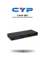
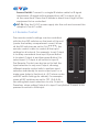
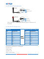
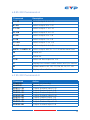
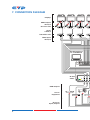
CMIR-882 8×8 Bi-directional Infrared Matrix Operation Manual DISCLAIMERS The information in this manual has been carefully checked and is believed to be accurate. Cypress Technology assumes no responsibility for any infringements of patents or other rights of third parties which may result from its use. Cypress Technology assumes no responsibility for any inaccuracies that may be contained in this document. Cypress also makes no commitment to update or to keep current the information contained in this document. Cypress Technology reserves the right to make improvements to this document and/or product at any time and without notice. COPYRIGHT NOTICE No part of this document may be reproduced, transmitted, transcribed, stored in a retrieval system, or any of its part translated into any language or computer file, in any form or by any means— electronic, mechanical, magnetic, optical, chemical, manual, or otherwise—without express written permission and consent from Cypress Technology. © Copyright 2011 by Cypress Technology. All Rights Reserved. Version 1.1 August 2011 TRADEMARK ACKNOWLEDGMENTS All products or service names mentioned in this document may be trademarks of the companies with which they are associated. SAFETY PRECAUTIONS Please read all instructions before attempting to unpack, install or operate this equipment and before connecting the power supply. Please keep the following in mind as you unpack and install this equipment: • Always follow basic safety precautions to reduce the risk of fire, electrical shock and injury to persons. • To prevent fire or shock hazard, do not expose the unit to rain, moisture or install this product near water. • Never spill liquid of any kind on or into this product. • Never push an object of any kind into this product through any openings or empty slots in the unit, as you may damage parts inside the unit. • Do not attach the power supply cabling to building surfaces. • Use only the supplied power supply unit (PSU). Do not use the PSU if it is damaged. • Do not allow anything to rest on the power cabling or allow any weight to be placed upon it or any person walk on it. • To protect the unit from overheating, do not block any vents or openings in the unit housing that provide ventilation and allow for sufficient space for air to circulate around the unit. REVISION HISTORY VERSION NO. DATE DD/MM/YY SUMMARY OF CHANGE VS0 26/03/12 Updated format/diagrams VR0 30/04/12 Preliminary Release VS1 24/07/12 IR Codes/RS-232 updated VR2 02/11/12 Updated RS-232 Command table B CONTENTS 1. Introduction�������������������������������������������� 1 2. Applications������������������������������������������� 1 3. Package Contents�������������������������������� 1 4. System Requirements���������������������������� 1 5. Features������������������������������������������������� 2 6. Operation Controls and Functions������� 3 6.1 Front Panel����������������������������������������3 6.2 Rear Panel�����������������������������������������4 6.3 Remote Control��������������������������������5 6.4 IR Data Codes����������������������������������6 6.5 DIP Switch Settings���������������������������6 6.6 IR Cable Pin Assignment�����������������7 6.7 RS-232 Pin Assignment���������������������7 6.8 RS-232 Commands A�����������������������8 6.9 RS-232 Commands B������������������������8 7. Connection Diagram���������������������������� 9 8. Specifications�������������������������������������� 11 9. Acronyms��������������������������������������������� 12 1. INTRODUCTION The Bi-directional Infrared Matrix is designed to work alongside the 8×8 HDMI matrix, providing control of up to 8 source devices from up to 8 display locations. Using the original or programmable remote controls, source devices such as DVD/Blu-ray players or satellite/set-top boxes can be controlled from any location. 2. APPLICATIONS • Control multiple sources and displays via bi-directional Infrared signals • Extending the range of existing systems • Long distance Infrared control 3. PACKAGE CONTENTS • 8×8 Bi-directional Infrared Matrix • Remote Control (CR110) with battery • 5 V/2.6 A DC Power Adaptor • 9×IR Extender cables • 9×IR Blaster cables • Operation Manual 4. SYSTEM REQUIREMENTS IR controllable Source equipment (e.g. DVD or Blu-ray players), IR controllable Display/ TV/monitors and HDMI/video matrix devices. 1 5. FEATURES • Supports independent IR input and output selection and control • Supports an IR frequency range of 30 kHz~50 kHz • Use your existing remote controls or programmable/universal remote controls • Supports bi-directional IR from input and output locations • Supports RS-232 control, IR remote control and on-panel control • 1U size design Note: This device does not support the sending of audio/video signals, it only transmits and receives infra-red signals. 2 6. OPERATION CONTROLS AND FUNCTIONS 6.1 Front Panel 8x8 IR Matrix 1 2 3 4 5 6 7 8 IR 1 2 Power All Lock Enter 3 4 5 6 7 1 LCM: Displays the setting information of each input and output setting. 2 IR: IR Receiver window (accepts the remote control signal of this device only). 3 Power: Press this button to power the device on/off. The LED will illuminate green when the power is on, red when it is in 'Standby' mode. 4 All: Press this button to select all IR output with one IR input signal. The sequence should be: ALLNumber KeyENTER. 5 Lock: Press this button to lock all the buttons on the panel; press again to unlock. The LED will illuminate green when locked. 6 Enter: Press this button to confirm when changing a setting. If this button is not pressed within 20 seconds the selection is cancelled. 7 1~8/A~H: Use these buttons to select which source is selected for control in each output location. Press a number key to select fromt TV A to TV H channels and press a number key again to select from Source 1 to Source 8 channels. Press 'Enter' to confirm the selection. 3 Note: Press 'All', 'Enter' and '1' together to switch the RS-232 baud rate to 9600 bps or press 'All', 'Enter' and '2' together to switch baud rate to 19200 bps. The LCM will display the current baud rate setting for few seconds. 6.2 Rear Panel A RS232 AUX B C D TV E F G H All Out 1 2 3 4 SOURCE 5 6 7 8 All DC 5V RS232 MAIN In 1 2 3 4 5 1 RS-232 AUX: Connect to a device that can be controlled (via D-Sub 9-pin male cable) by RS-232 commands e.g. the 8x8 HDMI Matrix. 2 RS-232 MAIN: Connect to a PC or control system with D-Sub 9-pin male cable for the transmission of RS-232 commands. 3 TV In A~H: Connect to the supplied IR extender cables for IR signal reception, the signal will be relayed to the designated source device via the IR Blaster. Ensure that the remote being used is within the direct line-of-sight of the IR extenders. TV In All: Connect to a single IR extender cable for IR signal reception, the signal will be relayed to all Source outputs (1~8) at the same time. Ensure that the remote being used is within the direct line-of-sight of the IR extender. TV Out A~H: Connect to the supplied IR blaster cables for IR signal transmission, IR signals will be relayed from the designated Source IR extender. Place the IR blasters in direct line-of-sight of the equipment to be controlled. TV Out All: Connect to a single IR blaster cable for IR signal transmission, IR signals will be relayed from all Source inputs (1~8) at the same time. Place the IR blaster in direct line-of-sight of the equipment to be controlled. 4 Source In 1~8: Connect to the supplied IR extender cables for IR signal reception the signal will be relayed to the designated TV output device via the IR Blaster. Ensure that the remote being used is within the direct line-of-sight of the IR extenders. Source In All: Connect to a single IR extender cable for IR signal reception, the signal will be relayed to all TV outputs (A~H) at the same time. Ensure that the remote being used is within the direct line-of-sight of the IR extender. Source Out 1~8: Connect to the supplied IR blaster cables for IR signal transmission, IR signals will be relayed from the designated TV output IR extender. Place the IR blasters in direct line-of-sight of the equipment to be controlled. 4 Source Out All: Connect to a single IR blaster cable for IR signal transmission, IR signals will be relayed from all TV outputs (A~H) at the same time. Place the IR blaster in direct line-of-sight of the equipment to be controlled. 5 DC 5V: Plug the 5V DC power supply into the unit and connect the adaptor to an AC outlet. 6.3 Remote Control The remote control's settings can be controlled with the four DIP switches on the back of the unit (under the battery compartment cover). When all the DIP switches are set to ON () the remote control is able to control all the input settings for all outputs. For example, to set Output A to relay commands from Input 5 press Button A to select Output A and then press Button 5 to select Input 5, Output A will switch to Input 5. 1 A 2 B 3 C 4 D 5 E 6 F The Remote Control can also be set to limit the 7 G Input selection to only one Output, allowing 8 H different remote control units to perform input IN OUT selection individually for each output port i.e. a single zone (refer to Section 6.6 - IR Custom codes and DIP switch Settings for details). For example, CR-110 when all DIP switches are set to OFF (), this setting limits input selections to only Output A. Therefore, when setting Output A to input 3 only Button 3 needs to be pressed to switch to that input. 5 6.4 IR Data Codes NO. DATA NO. DATA 1 88 A 8A 2 8C B 8E 3 90 C 92 4 85 D C6 5 C2 E 99 6 9C F 98 7 D8 G 84 8 87 H 97 6.5 DIP Switch Settings SELECT DIPSWITCH CUSTOM CODE Output A Output B Output C Output D Output E Output F Output G Output H 807F 807B 8077 8073 803F 803B 8037 8033 6 6.6 IR Cable Pin Assignment IR Blaster 1 Power 5 V 2 IR Blaster Signal 3 NC IR Extender 1 IR Signal 2 Power 5 V 3 Grounding Note: Both the IR Extender and Blaster support a frequency of 30~50 kHz. 6.7 RS-232 Pin Assignment CMIR-882 REMOTE CONTROL CONSOLE PIN Assignment PIN Assignment 1 NC 1 NC 2 Tx 2 Rx 3 Rx 3 Tx 4 NC 4 NC 5 GND 5 GND 6 NC 6 NC 7 NC 7 NC 8 NC 8 NC 9 NC 9 NC Baud Rate: 19200 bps/A or 9600bps/B Data Bit: 8-bit Parity: None Stop Bit: 1-bit Flow Control: None 7 6.8 RS-232 Commands A Command Description A1~A8 Switch output A to 1~8 B1~B8 Switch output B to 1~8 C1~C8 Switch output C to 1~8 D1~D8 Switch output D to 1~8 E1~E8 Switch output E to 1~8 F1~F8 Switch output F to 1~8 G1~G8 Switch output G to 1~8 H1~H8 Switch output H to 1~8 ABCD...1~ABCD...8 Switch output ABCD... To 1~8 at the sam Time P0 Power off P1 Power on I1~I8 Switch all the output to 1~8 ST Display the current matrix status and f/w version RS System reset to A1, B2, C3, D4, E5, F6, G7, H8 ? Display all available commands 6.9 RS-232 Commands B Command POWER 00 POWER 01 PORT 11~18 PORT 21~28 PORT 31~38 PORT 41~48 PORT 51~58 PORT 61~68 PORT 71~78 PORT 81~88 Action Power Off (standby) Power On Output A select Input 1~8 Output B select Input 1~8 Output C select Input 1~8 Output D select Input 1~8 Output E select Input 1~8 Output F select Input 1~8 Output G select Input 1~8 Output H select Input 1~8 8 7. CONNECTION DIAGRAM ZONE A ZONE B ZONE C ZON Displays HDMI Outputs IR Out/In Receiver Units RX Power Link IR 2 IR 1 Extender Blaster RS232 Out CAT5e/6 In RX Power Link IR 2 IR 1 Extender Blaster RS232 Out CAT5e/6 In RX Power RX Link IR 2 IR 1 Extender Blaster RS232 Out CAT5e/6 In Power IR 1 Extender B Single CAT5e/6 Transmitter Units TX PowerDC 24V Link IR 2 IR 1 Blaster Extender RS232 In CAT5e/6 Out TX PowerDC 24V Link IR 2 IR 1 Blaster Extender RS232 In CAT5e/6 Out TX PowerDC 24V TX Link IR 2 IR 1 Blaster Extender RS232 In CAT5e/6 Out PowerDC 24V IR 1 Blaster E HDMI Inputs IR Out/In RS-232 Equipped PC or Notebook A RS232 AUX B C D TV E F RS232 MAIN RS-232 Cable HDMI Outputs Source Equipment IR Source Inputs/Outputs 9 LAN A HDMI Out B HDMI Out C HDMI O 1 HDMI In 2 HDMI In 3 HDMI 1 2 3 IR-In RS-232 Service ZONE E NE D ZONE F ZONE G ZONE H IR In (All) RX Link IR 2 Blaster RS232 Out IR 2 Extender RS232 In CAT5e/6 In Power TX Link CAT5e/6 Out PowerDC RX Link IR 2 IR 1 Extender Blaster RS232 Out 24V CAT5e/6 In TX Link IR 2 IR 1 Blaster Extender RS232 In CAT5e/6 Out Power PowerDC RX Link IR 2 IR 1 Extender Blaster RS232 Out 24V CAT5e/6 In TX Link IR 2 IR 1 Blaster Extender RS232 In CAT5e/6 Out Power Link IR 2 IR 1 Extender Blaster PowerDC RS232 Out 24V CAT5e/6 In Link IR 2 IR 1 Blaster Extender RS232 In CAT5e/6 Out RX TX Power Link IR 2 IR 1 Extender Blaster PowerDC RS232 Out 24V CAT5e/6 In IR Out (All) Link IR 2 IR 1 Blaster Extender RS232 In CAT5e/6 Out 60° 3m F G H All Out 1 2 3 4 SOURCE 5 6 7 8 Power Supply All DC 5V 3m 7m m IR EXTENDER In 1.5m 8×8 IR Matrix 60° 8×8 HDMI Matrix Out D HDMI Out E HDMI Out F HDMI Out G HDMI Out H HDMI Out V+ GND In 3 4 HDMI In 5 HDMI In 6 HDMI In 7 HDMI In 8 HDMI In 4 5 6 7 8 GND 3 4 1 2 V+ Power Supply IR BLASTER GND DC 24V IR Out (All) IR In (All) 10 8. SPECIFICATIONS IR Frequency 30 kHz to 50 kHz Source Ports 8×Independent IR Blasters 8×Independent IR Extenders 1×All IR Blaster Control 1×All IR Extender Control TV Ports 8×Independent IR Extenders 8×Independent IR Blasters 1×All IR Blaster Control 1×All IR Extender Control Power Supply 5 V/2.6 A DC (US/EU standards, CE/FCC/ UL certified) ESD Protection Human body model: ±8 kV (air-gap discharge) ±4 kV (contact discharge) Dimensions 432 mm (W)×174 mm (D)×44 mm (H) Weight 2206 g Chassis Material Aluminum Silkscreen Color Black Operating Temperature 0 ˚C~40 ˚C/32 ˚F~104 ˚F Storage temperature −20 ˚C~60 ˚C/−4 ˚F~140 ˚F Relative Humidity 20~90 % RH (non-condensing) Power Consumption 1W 11 9. ACRONYMS ACRONYM COMPLETE TERM IR Infrared LCM Liquid Crystal Module 12 CYPRESS TECHNOLOGY CO., LTD Home page: http://www.cypress.com.tw 20130219 MPM-CMIR882


![[ITA] RX40 Manuale v1-5](http://vs1.manualzilla.com/store/data/006119954_1-2ba2af64dd7b8b55c335fa8e9797796a-150x150.png)