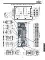
1
MODEL W1709
20" WIDE BELT SANDER
INSTRUCTION MANUAL
Phone: 1-360-734-3482 • On-Line Technical Support: [email protected]
COPYRIGHT © SEPTEMBER, 2003 BY WOODSTOCK INTERNATIONAL, INC.
WARNING: NO PORTION OF THIS MANUAL MAY BE REPRODUCED IN ANY SHAPE OR FORM WITHOUT
THE WRITTEN APPROVAL OF WOODSTOCK INTERNATIONAL, INC.
Printed in Taiwan
WARNING
Some dust created by power sanding, sawing,
grinding, drilling, and other construction activities
contains chemicals known to the State of California
to cause cancer, birth defects or other reproductive
harm. Some examples of these chemicals are:
• Lead from lead-based paints.
• Crystalline silica from bricks, cement, and
other masonry products.
• Arsenic and chromium from chemically
treated lumber.
Your risk from these exposures varies, depending on
how often you do this type of work. To reduce your
exposure to these chemicals: work in a well
ventilated area, and work with approved safety
equipment, such as those dust masks that are
specially designed to filter out microscopic
particles.
PAGE
INTRODUCTION ..............................................................................................2
About Your New Sander ..............................................................................2
Woodstock Service and Support......................................................................2
Warranty and Returns..................................................................................3
Specifications ..........................................................................................3
INTRODUCTION
CONTENTS
SAFETY
ASSEMBLY ....................................................................................................9
Unpacking................................................................................................9
Box Contents ............................................................................................9
Shop Preparation ......................................................................................10
Cleaning Machine ....................................................................................10
Air Hose Installation ..................................................................................11
Sanding Belt installation ............................................................................11
Shipping Plug ..........................................................................................12
Dust Collection ........................................................................................12
ASSEMBLY
ADJUSTMENTS ............................................................................................13
General Information ..................................................................................13
Photo-Electric Eye ....................................................................................13
Belt Tracking ..........................................................................................14
Belt Oscillation Speed ................................................................................15
Belt Tracking Safety Switch ........................................................................16
Belt Tension Safety Switch ..........................................................................16
Pressure Rollers ......................................................................................17
V-Belt Tension ........................................................................................18
Feed Belt Tension and Tracking ....................................................................19
Table Stop Switches ..................................................................................20
ADJUSTMENTS
MAINTENANCE ............................................................................................26
General ................................................................................................26
Lubrication ............................................................................................26
Cleaning Belts ........................................................................................27
Servicing Separators ..................................................................................27
Servicing Brake ........................................................................................28
Changing V-Belts ......................................................................................29
Troubleshooting ......................................................................................30
Wiring Diagrams ......................................................................................31
PARTS
PARTS ......................................................................................................31
Parts Breakdown and Parts Lists....................................................................34
Accessories ............................................................................................46
MAINTENANCE
OPERATIONS ..............................................................................................21
Control Panel ..........................................................................................21
Test Run ................................................................................................22
Selecting Sandpaper ..................................................................................22
Setting Feed Speed ..................................................................................23
Using the Load Meter ................................................................................23
Emergency Stop ......................................................................................24
Keypad and Display ..................................................................................24
Calibrating the Table ................................................................................24
Basic Sanding ..........................................................................................25
OPERATIONS
SAFETY ......................................................................................................4
Standard Safety Instructions..........................................................................4
Additional Safety Instructions for Sanders ........................................................6
Avoiding Potential Injuries ............................................................................7
Electrical Requirements ..............................................................................8
220V Operation ........................................................................................8
Extension Cords ........................................................................................8
Grounding................................................................................................8
INTRODUCTION
INTRODUCTION
About Your New Sander
Your new SHOP FOX® Sander has been specially designed to provide many years of trouble-free
service. Close attention to detail, ruggedly built parts and a rigid quality control program assure safe
and reliable operation.
This compact wide-belt sander has digital controls and readout for setting your sanding depth
automatically. You can easily and very accurately sand flat boards up to 20" wide resulting in a very
smooth and flat finish. Your sander has independent motor controls, an emergency safety shut off bar,
a built-in air regulator and filter, an emergency disc brake and a motorized table elevation control.
Other great features that you will enjoy is the adjustable photo-electric belt oscillation system, the
sanding load meter, and a quick-change belt system with automatic belt tensioning.
Woodstock International, Inc. is committed to customer satisfaction in providing this manual. It is our
intent to make sure all the information necessary for safety, ease of assembly, practical use and
durability of this product be included.
If you need the latest edition of this manual, you can download it from http://www.shopfox.biz.
If you still have questions after reading the latest manual, or if you have comments please contact us at:
Woodstock International, Inc.
Attn: Technical Support Department
P.O. Box 2309
Bellingham, WA 98227
Woodstock Service and Support
We stand behind our machines! In the event that a defect is found, parts are missing or questions arise
about your machine, please contact Woodstock International Service and Support at 1-360-734-3482 or
send e-mail to: [email protected]. Our knowledgeable staff will help you troubleshoot
problems, send out parts or arrange warranty returns.
-2-
Woodstock International, Inc. warrants all SHOP FOX® machinery to be free of defects from
workmanship and materials for a period of 2 years from the date of original purchase by the original
owner. This warranty does not apply to defects due directly or indirectly to misuse, abuse, negligence
or accidents, lack of maintenance, or to repairs or alterations made or specifically authorized by
anyone other than Woodstock International, Inc.
Woodstock International, Inc. will repair or replace, at its expense and at its option, the SHOP FOX®
machine or machine part which in normal use has proven to be defective, provided that the original
owner returns the product prepaid to the SHOP FOX® factory service center or authorized repair
facility designated by our Bellingham, WA office, with proof of their purchase of the product within 2
years, and provides Woodstock International, Inc. reasonable opportunity to verify the alleged defect
through inspection. If it is determined there is no defect, or that the defect resulted from causes not
within the scope of Woodstock International Inc.'s warranty, then the original owner must bear the
cost of storing and returning the product.
This is Woodstock International, Inc.'s sole written warranty and any and all warranties that may be
implied by law, including any merchantability or fitness, for any particular purpose, are hereby
limited to the duration of this written warranty. We do not warrant that SHOP FOX® machinery
complies with the provisions of any law or acts. In no event shall Woodstock International, Inc.'s
liability under this warranty exceed the purchase price paid for the product, and any legal actions
brought against Woodstock International, Inc. shall be tried in the State of Washington, County of
Whatcom. We shall in no event be liable for death, injuries to persons or property or for incidental,
contingent, special or consequential damages arising from the use of our products.
Every effort has been made to ensure that all SHOP FOX® machinery meets high quality and durability
standards. We reserve the right to change specifications at any time because of our commitment to
continuously improve the quality of our products.
Specifications
Sanding Motor ..................................................71⁄2 HP, 40 Amp, 220V, Single-Phase
Sanding Motor Speed ..........................................................................1,725 RPM
Feed Motor ......................................................1⁄2 HP, 3.8 Amp, 220V, Single-Phase
Feed Motor Speed ..............................................................................1,725 RPM
Elevation Motor ....................................................1⁄3 HP, 3Amp, 220V, Single-Phase
Elevation Motor Speed ........................................................................1,725 RPM
Drum Speed......................................................................................3,550 FPM
Drum Diameter ......................................................................................713⁄16"
Feed Rates ......................................................................16.4, 23, and 32.8 FPM
Sanding Belt Size ..............................................................................201⁄2" x 48"
Total Amps (All motors under maximum load) ..............................................47 Amps
Maximum Sanding Width ..............................................................................20"
Maximum Sanding Thickness ............................................................................6"
Minimum Stock Length ..................................................................................9"
Minimum Stock Thickness ..............................................................................1⁄8"
Footprint ......................................................................311⁄4" wide x 161⁄2" deep
Height (With dust port installed) ..................................................................601⁄4"
Operating Air Pressure ..............................................................................57 PSI
Dust Port ..................................................................................................4"
Machine Weight ....................................................................................961 lbs
-3-
INTRODUCTION
INTRODUCTION
Warranty and Returns
SAFETY
SAFETY FIRST!
READ MANUAL BEFORE OPERATING MACHINE.
FAILURE TO FOLLOW INSTRUCTIONS BELOW WILL
RESULT IN PERSONAL INJURY.
Indicates an imminently hazardous situation which, if not avoided, WILL
result in death or serious injury.
Indicates a potentially hazardous situation which, if not avoided, COULD
result in death or serious injury.
Indicates a potentially hazardous situation which, if not avoided, MAY
result in minor or moderate injury, MAY result in property damage.
NOTICE
This symbol is used to alert the user to useful information about proper
operation of the equipment.
Standard Safety Instructions
1. Thoroughly read the instruction manual before operating your machine. Learn the applications,
limitations and potential hazards of this machine. Keep manual in a safe, convenient place for
future reference. Make sure any other operators have read and understand the manual as well.
2. Keep work area clean and well lighted. Clutter and inadequate lighting invite potential hazards.
3. Ground all tools. If a machine is equipped with a three-prong plug, it must be plugged into a
three-hole grounded electrical outlet or grounded extension cord. If using an adapter to aid in
accommodating a two-hole receptacle, ground using a screw to a known ground.
4. Wear eye protection at all times. Use safety glasses with side shields or safety goggles that meet
the national safety standards, while operating this machine.
5. Avoid dangerous environments. Do not operate this machine in wet or open flame environments.
Airborne dust particles could cause an explosion and severe fire hazard.
6. Ensure all guards are securely in place and in working condition.
7. Make sure switch is in the “OFF” position before connecting power to machine.
8. Keep work area clean, free of clutter, grease, etc.
9. Keep children and visitors away. Visitors should be kept at a safe distance away while operating
unit.
10. Childproof workshop with padlocks, master switches or by removing starter keys.
11. Disconnect machine when cleaning, adjusting or servicing.
-4-
12. Do not force the machine. The machine will do a safer and better job if it does the work.
13. Use the correct tool. Do not force the tool or attachment to do a job for which it was not
designed.
14. Wear proper apparel. Do not wear loose clothing, gloves, jewelry, keep long hair tied up, etc.
16. DO NOT use extension cord. Due to the high-amperage draw of this industrial machine, we do not
recommend using an extension cord. If you use an extension cord with an undersized gauge or one
that is too long, excessive heat will be generated within the circuit increasing the chance of a fire
or damage to the circuit.
17. Keep stable footing and balance at all times.
18. Do not leave machine unattended. Wait until it comes to a complete stop before leaving the
area.
19. Perform machine maintenance and care. Follow lubrication and accessory attachment
instructions in the manual.
20. Keep machine away from open flame. Operating machines near pilot lights and/or open flames
creates a high risk if dust is dispersed in the area. Dust particles and an ignition source may cause
an explosion. Do not operate the machine in high-risk areas, including but not limited to, those
mentioned above.
21. If at any time you are experiencing difficulties performing the intended operation, stop using the
machine! Then contact our Service Department or ask a qualified expert how the operation should
be performed.
22. Habits—good and bad—are hard to break. Develop good habits in your shop and safety will
become second-nature to you.
WEAR safety glasses or goggles when
operating equipment. Operating this
equipment creates the potential for flying
debris to cause eye injury. Everyday glasses
or reading glasses only have impact resistant
lenses, they are not safety glasses. Be certain
the safety glasses you wear meet the
appropriate standards of the American
National Standards Institute (ANSI).
-5-
SAFETY
15. Remove adjusting keys and wrenches. Before turning the machine on, make a habit of checking
that all adjusting keys and wrenches have been removed before turning the machine ON.
Additional Safety Instructions for Sanders
SAFETY
READ and understand this
entire instruction manual
before using this machine.
Serious personal injury
may occur if safety and
operational information is
not
understood
and
followed. DO NOT risk your
safety by not reading!
USE this and other machinery with caution and
respect, and always consider safety first, as it
applies to your individual working conditions.
Remember, no list of safety guidelines can be
complete, and every shop environment is
different. Failure to follow guidelines can
result in serious personal injury, damage to
equipment and/or poor work results.
1.
Always wear a dust mask. Sanding operations create large amounts of fine dust. Some types of
dust may cause allergic reactions or respiratory problems. In addition to wearing a dust mask,
always use a dust collector and overhead air filter for maximum protection.
2.
Do not allow your fingers to get pinched between the board and the conveyor belt during
feeding. The grip of the conveyor belt may pull the operator’s hand into the machine and cause
serious injury or death. Similarly, do not place hands near the sanding belts during operation.
3.
Know the limits of the sander. Do not sand stock thinner than 1⁄8" or shorter than 10".
4.
Never perform sanding operations with the access doors open.
5.
Always inspect stock for staples, nails, dirt or other foreign objects before sanding. These
items may cause damage to your sander or may even be thrown at a high rate of speed from the
sander at the operator.
6.
Never allow anyone to stand directly in front or behind the path of the stock as it is being fed
through the sander. The stock may be ejected at a high rate of speed and could cause serious
injury to the operator or bystanders.
7.
Treat your sander with respect. Do not force stock into the sander during operation or overload
the sanding drums beyond reasonable limits. Also, only sand natural wood fiber through your
sander. Other materials may damage your machine and open the possibility for operator injury.
Keep the internal components clean and lubricated to ensure that the sander can perform the
way it was intended.
8.
Never operate the sander without a working dust collection system. The sander is designed to
properly do its job only when wood dust is being evacuated. The buildup of too much wood dust
in the internal components will cause performance problems and may increase the likelihood of
operator injury.
9.
Wear the proper clothing during all operation and adjustments. Loose clothing or long hair
creates the potential for operator injury because they can easily be caught in the moving parts of
the machine. Roll up loose sleeves, tie back long hair and take any other necessary steps to
reduce this hazard.
-6-
Avoiding Potential Injuries
SAFETY
Figure 1. Correct body and hand positioning.
Figure 2. DO NOT operate without safety
glasses/respirator!
Figure 3. DO NOT stand behind workpiece!
Figure 4. DO NOT operate with side door open!
Figure 5. DO NOT allow hand to get pinched in belt!
-7-
SAFETY
Electrical Requirements
220V Operation
The SHOP FOX® Model W1709 has a 71⁄2 HP,
220V single-phase sanding motor, a 1⁄2 HP,
220V feed motor, and a 1⁄3 HP table lift motor.
TURN-OFF and LOCK
your
master
power
switch so no power is
available to the sander
before
connecting
electrical wires! If you
ignore this warning
serious electrical shock
may occur causing injury
or death!
Use a 50 amp circuit breaker and a circuit that
has wiring rated to handle this amperage draw.
Keep in mind that a circuit being used by other
machines or tools at the same time will add to
the total load being applied. Add up the load
ratings of all machines on the circuit. If this
number exceeds the rating of the circuit
breaker or wiring, use a different circuit.
Extension Cords
Any electrical outlet and
circuit that you plug your
machine into must be
grounded. Never remove
the grounding pin from any
plug, and always make sure
all wiring to the machine is
grounded before operating.
Serious injury may occur if
this warning is ignored!
DO NOT use an extension cord for 220V high
amperage industrial shop machines. We
recommend following all local electrical codes
and using a direct hard wired power supply
that is protected by a circuit breaker and is
equipped with a kill switch lever that can be
locked in the OFF position.
Grounding
This machine must be grounded! Hardwire this
machine into a power supply circuit that
contains a ground circuit. If you have any
questions about correct electrical installation,
contact a qualified electrician for assistance to
make sure all connections are safe and adhere
to your local electrical codes.
DO NOT replace the circuit breaker with
one rated at a higher amperage or damage
to the circuit may occur.
-8-
ASSEMBLY
Unpacking
The Model W1709 has been carefully packaged
for safe transporting. If you notice the machine
has been damaged, please contact Woodstock
International Service and Support at 1-360-7343482 or send e-mail to:
[email protected].
Box Contents
The following is a description of the
components shipped with the SHOP FOX®
W1709. Lay the components out in a similar
fashion to those in Figure 6. This will help in
identification before beginning assembly.
Should any part be missing, examine the
packaging carefully. If any parts are missing,
find the part number in the back of this manual
and call Woodstock International, Inc. at 360734-3482 or e-mail:
[email protected].
Item
The Model W1709 is a
heavy machine at 1,870
lbs. Use power or
hydraulic equipment to
avoid serious personal
injury or death.
Qty.
Combination Wrench 8 x 10mm ................(1)
Combination Wrench 12 x 14mm ..............(1)
Combination Wrench 17 x 10mm ..............(1)
Phillips Screwdriver ..............................(1)
Standard Screwdriver ............................(1)
Hex Wrench Set (10-Piece 1.5-10mm) ........(1)
Square-Key Door Handle ........................(2)
Sanding Belt ........................................(2)
4-Amp Fuse Bag (Located Inside of Power Box)(2)
Sander (Not Shown) ..............................(1)
Tool Box (Not Shown) ............................(1)
Dust Port (Not Shown) ............................(1)
Dust Port Adapter (Not Shown) ................(1)
Ceramic Wear Rods (Not Shown) ..............(2)
Figure 6. Parts shipped with the sander.
-9-
ASSEMBLY
READ and understand this
entire instruction manual
before performing any
operations with your
machine. Personal injury
may occur if safety and
operational information is
not
understood
and
followed.
Shop Preparation
ASSEMBLY
•
•
•
Cleaning Machine
Floor Load and Balance: Your sander
represents a large weight load in a small
footprint. Most commercial floors are
suitable for the sander. Some residential
floors may require additional bracing to
support both machine and operator. Make
sure the sander operates on a level
surface by placing a level gauge on the
conveyor table and using a wrench to
adjust the feet until the machine is level.
The upper roller of the Model W1709 is coated
with a waxy grease that protects it from
corrosion during shipment. This coating must
be removed before using your sander.
Clean this grease off with a solvent cleaner or
citrus-based degreaser. Do not use chlorinebased solvents—if you happen to splash some
onto a painted surface, you will ruin the finish.
Working Clearances: Consider existing and
anticipated needs, size of material to be
processed through each machine, and
space for auxiliary stands, work tables or
other machinery when establishing a
location for your sander.
NEVER use flammables
such as gas or other
petroleum-based solvents
to clean your machine.
These products have low
flash points and present
the risk of explosion and
severe personal injury!
Lighting and Outlets: Lighting should be
bright enough to eliminate shadows and
prevent eye strain. Electrical circuits
should be dedicated or large enough to
handle amperage requirements. Outlets
should be located near each machine so
any power or extension cords are clear of
high-traffic areas. Observe local electrical
codes for proper installation of new
lighting, outlets, or circuits.
NEVER smoke when using
solvents. Smoking may
cause explosion or risk of
fire when exposed to these
products!
MAKE SURE that all
entrances to your shop are
locked or that machines
are equipped with safety
lock-out devices to protect
curious children or visitors
from serious injury. Never
allow unsupervised people
in your shop who have not
been fully trained!
WORK in a well ventilated
area when using solvents,
and keep away from any
potential ignition sources
(pilot
lights).
Most
solvents used to clean
machinery are toxic when
inhaled or ingested.
When
using
these
products, Always dispose
of any waste rags in a
sealed container to make
sure they do not cause
fire or environmental
hazards.
-10-
Air Hose Installation
Push your air supply hose on to the air pressure
regulator inlet fitting, and clamp it in place
with a hose clamp as shown in Figure 7. If you
prefer, you can replace the included air nozzle
with a 3⁄8" male quick connect air coupling.
When the air hose is installed, pull up and
rotate the regulator air pressure knob until the
gauge reads 57 PSI then push down. DO NOT
attempt to regulate the air pressure with the
ON/OFF air supply lever. This control only shuts
off air pressure to the machine.
Figure 7. Air hose attached to regulator.
Sanding Belt Installation
Before installing belt, clean the protective
grease from the upper metal sanding belt
roller as per the “Cleaning Machine”
instructions.
To install the sanding belt, do these steps:
1.
TURN-OFF and LOCK your master power
switch, but keep the air pressure going
into the machine.
2.
Turn and remove the lever and support
spacer. See Figure 8.
3.
Install the sanding belt with the arrows
pointing in the direction of drum rotation
and center the belt on the rollers. See
Figure 9.
4.
Reinstall the support spacer and lever.
5.
Turn the belt tension knob to the 12:00
position and the belt will automatically
tighten to the correct tension. At 9:00 the
belt will have no tension.
Figure 8. Lever removal/installation.
NOTICE
TENSION the sanding belt before starting
the sander, and DE-TENSION the belt when
sander is not in use, or you will damage the
belt.
Correct
Belt
Direction
Belt
Tension
Knob
Figure 9. Installing sanding belt.
-11-
ASSEMBLY
NOTICE
To achieve maximum life of the air system orings, gaskets, and components, keep the air
pressure shut off when not using the sander,
and DO NOT exceed75 PSI.
Dust Collection
The Model W1709 features a dust port and an
adapter located on top of the machine as
shown in Figures 10 and 11. Before performing
any sanding operation, attach the dust port to
a 2HP or better dust collector, which can draw
at least 1,200 CFMs, or dust buildup will hinder
the performance of your sander.
ASSEMBLY
Even with a sufficient dust collection system, a
fine layer of dust may still be present on your
stock as it comes out of the sander. This
residual dust is a normal condition.
DO NOT operate this
machine
without
an
adequate dust collection
system.
This
machine
creates substantial amounts
of wood dust while in
operation. Failure to use a
dust collection system can
result in short and longterm respiratory illness.
Figure 10. Dust collection adapters.
ALWAYS
wear
your
respirator in addition to
using a dust collector.
This machine produces
sawdust that may cause
allergic
reactions
or
respiratory problems.
Figure 11. Dust collection hose
attached to dust port.
-12-
ADJUSTMENTS
General Information
The adjustments in this section have been
factory set and generally do not need to be
performed when you first receive your sander.
However, before operating your sander become
familiar with these adjustments, as they will
help you achieve the sanding results you want.
KEEP loose clothing and
long hair secured and
away from moving
parts.
Photo-Electric Eye
Photo-Electric
Eye
The photo-electric eye senses when the belt
oscillates to the right and blocks the beam to
and from the reflector. See Figures 12 and 13.
As soon as the sanding belt obstructs the beam,
a piston changes the direction of belt movement
to the left. Should the adjustment of the photoelectric eye become skewed, you can readjust
the eye.
Mounting
Bolt
1.
Photo-Electric
Eye Mount
TURN-OFF and LOCK the master power
switch so no power can go to your sander,
but keep the air pressure going into the
machine.
2.
Make sure the air regulator is adjusted so
that system air pressure is 57 PSI.
3.
Open both upper access doors on the sander.
4.
Loosen the sanding belt tension and slide
the belt so the belt is positioned in the
middle of the rollers.
5.
Apply power to the sander and push the
emergency stop button in so the sander
cannot start.
6.
Loosen the photo-electric eye mounting bolt.
See Figure 12.
7.
Position the mount so the photo-electriceye beam is barely obstructed by the edge
of the belt, pointing at the reflector, and
you hear the electric solenoid click and the
piston pushes the pushrod outward. See
Figures 12 and 13.
8.
Tighten the mounting bolt.
9.
Start the sander, and check for correct belt
positioning and oscillation.
10. Repeat steps 1 through 9 until the photoelectric eye positioning is correct.
Figure 12. Photo-electric-eye assembly.
Reflector
Figure 13. Photo-electric-eye reflector.
-13-
ADJUSTMENTS
To adjust the photo-electric eye, do these
steps:
Belt Tracking
The belt tracking is adjusted by lengthening or
shortening a air cylinder pushrod (Figure 14).
This adjustment is responsible for keeping the
belt in “same-speed” left-to-right motion
during sanding. Your goal is to adjust the
pushrod length until the belt left-and-right
movement takes approximately the same
amount of time.
KEEP loose clothing and
long hair secured and
away from moving
parts.
KEEP your hands clear of the sanding belt
when making these adjustments!
Pushrod
ADJUSTMENTS
To adjust the belt tracking, do these steps:
1.
Make sure the air flow is set to 57 PSI at
the regulator.
2.
Put on safety glasses, tie back all loose
clothing, remove jewelry, pull back
sleeves, and tie back long hair so it will
not get caught by the sanding belt.
3.
Turn the sander ON.
4.
Observe the left-to-right motion of the
belt as it moves along the drum while
looking from the front of the sander.
Figure 14. Belt tracking adjustment location.
• If the belt tracks faster to the right, but
is slow to track back to the left, loosen
the jam nut and rotate the pushrod to
lengthen the rod until the tracking is
correct. See Figure 14.
• If the belt tracks faster to the left, but is
slow to track back to the right, loosen
the jam nut and rotate the pushrod to
shorten the rod until the tracking is
correct. See Figure 14.
5.
Make sure the belt tracks left and right at
approximately the same speed.
6.
Keep the sander running, and now
complete the Belt Oscillation Speed
adjustment as outlined on page 15.
Jam
Nut
-14-
Belt Oscillation Speed
For normal operations, the oscillation speed
should be set so that it takes approximately
one second to move each direction of travel,
or a total of two seconds to move both
directions.
KEEP loose clothing and
long hair secured and
away from moving
parts.
However, you can experiment with different
speeds to see how the results may affect your
finished product. Often, you may find that
certain speeds yield better results for different
varieties of stock and the feed rates chosen.
Needle
Valve
Jam
Nut
KEEP your hands clear of the sanding belt
when making these adjustments!
1.
Complete the Sanding Belt Tracking
adjustment on page 14.
2.
Put on safety glasses, tie back all loose
clothing, remove jewelry, pull back
sleeves, and tie back long hair so it will
not get caught by the sanding belt.
3.
If you have not already done so, turn the
sander ON.
4.
Looking from the front of the sander,
observe the left-to-right motion of the belt
as it moves along the drum while.
5.
Loosen the needle valve jam nuts. See
Figure 15.
6.
With your fingertips, turn both needle
valves counter-clockwise to increase the
oscillations, or turn clockwise to decrease
oscillations.
7.
When the belt oscillation is at the rate you
need, hold the needle valve, and with your
fingertips tighten the needle valve jam
nuts.
8.
Observe belt tracking and oscillation, and
complete the Sanding Belt Tracking
adjustment on page 14 if tracking is
slightly out of adjustment.
Figure 15. Belt oscillation adjustment.
-15-
ADJUSTMENTS
To set the belt oscillation speed, do these
steps:
Belt Tracking Safety
Switch
Adjustment
Bolt
Belt tracking safety switches are placed on
both sides of the belt to act as emergency
machine stops if the belt travels too far to one
side during oscillation. See Figure 16.
ADJUSTMENTS
To adjust the belt tracking safety switches,
do these steps:
1.
TURN-OFF and LOCK the master power
switch so no power can go to your sander!
2.
Make sure the belt tracking and oscillation
is adjusted.
3.
Release the belt tension, center the
sanding belt on the top roller, then retension the belt.
4.
Measure the distance from the edge of the
sanding belt to the ceramic rod protruding
from the switch.
5.
Loosen the adjustment bolt shown in Figure
16 and move the switch so the belt and the
ceramic rod have approximately 1⁄2"
clearance from each other.
6.
Tighten the bolt and repeat the adjustment
with the other side if necessary.
7.
Start the sander and make sure it is
working properly.
Figure 16. Tracking safety switch and
adjustment bolt.
-16-
Pressure Rollers
Belt
Tension
Knob
The pressure rollers are factory set so they are
parallel with each other, parallel with the
sanding drum, and parallel with the surface of
the conveyor table. Additionally, the front
pressure rollers must be set 0.040" below the
sanding drum, and the rear rollers at 0.020"
below the sanding drum. When these settings
are achieved, the pressure-roller spring tension
will be correct.
Pressure
Roller
Tension
Adjustments
and Jam Nuts
To adjust the pressure rollers, do these
steps:
TURN-OFF and LOCK the master power
switch so no power can go to your sander!
2.
Make two gauge boards that are 24" long
and uniform in thickness.
3.
Connect the air pressure and set it to 57 PSI.
4.
Install the sanding belt and turn the belt
tensioning knob to the 12:00 position to
tension the belt. See Figure 17.
5.
Position each board on each side of the
conveyor belt and directly below the front
and back pressure rollers. See Figure 18.
6.
Loosen the adjustment jam nuts and raise
the pressure rollers above the sanding belt
roller with the adjustment bolts shown in
Figure 17.
7.
Raise the table up until the boards barely
touch the sanding belt.
8.
Turn the table-height handwheel counterclockwise one complete turn to lower the
table approximately 0.020".
9.
Lower the rear pressure rollers so that both
ends barely touch the gauge boards. The
rear pressure rollers are now set at 0.020"
below the sanding drum.
Figure 17. Belt and pressure roller adjustments.
ADJUSTMENTS
1.
Figure 18. Gauge boards placed under pressure
rollers as a gauge.
10. Turn the table-height handwheel counterclockwise again one complete turn, which
lowers the table an additional 0.020".
11. Lower the front pressure rollers so that
both ends just touch the boards. The front
pressure rollers are now set at 0.040"
below the sanding drum.
12. Tighten the adjustment jam nuts.
-17-
V-Belt Tension
The sanding motor V-belts that drive the
sanding rollers (Figure 19) and the table lift
motor that adjust table height (Figure 20),
must be tensioned properly for best
performance. Only replace the belt if it
becomes frayed, cracked, or glazed. If one belt
is bad, always replace both belts as a matched
set. NOTE, Both table lift and sanding motor
belts are adjusted the same way.
Tension
Adjustment
Nut
ADJUSTMENTS
KEEP the sanding drum drive belts correctly
adjusted. If the belts are loose, and the
emergency stop is engaged, the sanding
drum pulley will slip and not immediately
stop in the event of an emergency!
Figure 19. Sanding motor v-belt adjustment.
To tension the V-belts, do these steps:
1.
TURN-OFF and LOCK the master power
switch so power cannot start your sander!
2.
Remove the lower cover(s) on the sander
(right cover for sanding belt motor, left
cover for the conveyor height motor).
3.
Turn both nuts clockwise to tighten the Vbelts, or turn both nuts counterclockwise
to loosen the V-belts.
4.
The V-belt is properly tightened when it
will move no more than 3⁄4" in the center
with moderate pressure from your thumb.
Tension
Adjustment
Nut
Figure 20. Table lift motor v-belt adjustment.
-18-
Feed Belt Tension
and Tracking
The feed belt tension and tracking has been set
at the factory; however, if at any point you
notice that your feed belt is slipping or
tracking off center on the rollers and loading
up on the positioning wheels under the
conveyor table, you must adjust the feed belt
tension and tracking.
To adjust the feed belt tension and tracking,
do these steps:
1.
Lift and hold the emergency stop plate up
and out of the way. See Figure 21.
2.
Turn the feed belt tension and tracking
bolts equal amounts from side-to-side and
set the belt tension so it is snug and will
not slip when sanding at a maximum load.
Feed Belt
Tension and
Tracking Bolt
Figure 21. Feed belt tension bolt shown with
with the emergency brake raised.
ADJUSTMENTS
KEEP loose clothing and
long hair secured and
away from moving
parts.
3.
Start the conveyor.
4.
Turn the feed belt tension and tracking
bolt to position the feed belt roller evenly
on each side. See Figure 21.
• If the conveyor tracks to the right, turn
the right-side tension and tracking bolt
clockwise in approximately 1⁄4 turn
increments.
• If the conveyor tracks to the left, turn
the left-side tension and tracking bolt
clockwise in approximately 1⁄4 turn
increments.
5.
Run the feed belt for at least three
minutes to determine if the tracking is
correct and the tension stays the same.
6.
Repeat steps as required to achieve the
correct tension and tracking.
7.
Test emergency stop operation.
-19-
Table Stop Switches
The table stop switches prevent the table lift
motor from running the table into the sanding
drum and bottoming out the table lift
mechanism at the end of the jack screws.
Periodically adjust the table stop switches.
ADJUSTMENTS
To adjust table stop switches, do these steps:
1.
Apply air to the sander and tension the
sanding belt.
2.
Push the down arrow key and lower the
table until you achieve 6 inches between
the sanding drum and the conveyor table
surface. See Figure 22.
3.
Loosen the mounting bolt for the tabledown stop switch and move the switch so
the switch plunger depresses against the
stop block and you hear the switch click.
See Figure 23.
4.
Re-tighten the mounting bolt.
5.
Push the up arrow key and raise the table
until you achieve an 1⁄8 inch between the
sanding drum and the conveyor table
surface.
6.
Loosen the mounting bolt for the table-up
stop switch and move the switch so the
switch plunger depresses against the stop
block and you hear the switch click. See
Figure 23.
7.
Re-tighten the mounting bolt.
8.
Use the up and down buttons and test the
table operation and make sure the
switches shut the table lift motor OFF
when the table is at the minimum and
maximum distance from the sanding drum.
Up and
Down
Key
Figure 22. Key pad table-lift controls.
Table Up
Stop Switch
Mounting
Bolt
Stop Block
Table Down
Stop Switch
Switch
Plungers
Figure 23. Table stop switch adjustment
locations.
-20-
OPERATIONS
Control Panel
• Table Start and Stop Keys:
Cycles the table lift motor in and out of
the automatic raise and lower function.
Below is a summary of your sander control
panel and the components that it controls. Use
this information to become familiar with your
sander. See Figure 24.
• Sanding Load Amp Meter:
Indicates the current amp load on the
sanding motor when a sanding operation
is in progress.
• Power Lamp:
Indicates when machine has power to
the control panel.
• Digital Readout: Displays current sander
settings.
• Emergency Stop Button:
Stops all electrical power to motors in
event of emergency, and stops sanding
drums with an air-disc brake.
• Input LED: Indicates the sander is waiting
for new numerical dimension values.
• Sanding Belt Start and Stop Buttons:
Cycles the sanding motor ON and OFF if
the sander has air pressure and the belt is
tensioned.
• Run LED: Indicates the conveyor lift
motor is operating.
• Key Pad: Allows you to input your
numerical sanding specifications for
automated sanding control.
• Feed Belt Start and Stop Buttons:
Cycles the conveyor motor ON and OFF
for feeding wood into the sander.
• Table Up and Down Keys:
Manually cycles the table lift motor to
raise and lower the table.
Sanding
Belt
Start
Button
Sanding
Belt Stop
Button
Input
LED
Digital
Readout
Table
Up
Key
Run
LED
Key
Pad
Table
Down
Key
Table
Set
Key
Table
Stop
Key
Figure 24. Control panel interface.
-21-
Table
Start
Key
Feed
Belt
Start
Button
Feed
Belt
Stop
Button
Power
Lamp
OPERATIONS
Sanding
Load
Amp
Meter
Emergency
Stop
Button
Test Run
Once assembly is complete, the machine is
ready for a test run. The purpose of a test run
is to identify any unusual noises and vibrations,
as well as to confirm that the machine is
performing as intended.
ALWAYS
wear
safety
glasses and a respirator
during operations. Serious
injury may occur if this is
warning is ignored!
OPERATIONS
To complete the test run, do these steps:
1.
Tie back loose clothing and hair, and wear
a respirator and safety glasses.
2.
Apply power to the sander and connect the
supply air to the sander. Make sure the air
pressure is set at 57 PSI.
3.
Make sure the sanding belt is tensioned.
4.
Make sure all access doors and handles are
secured.
5.
Start the dust collection system.
6.
Turn the sander and feed belt ON.
7.
Listen for any unusual noises. The machine
should run smoothly with little or no
vibrations.
KEEP loose clothing and
long hair secured and
away from moving
parts.
ALWAYS wear hearing
protection during sanding
operations. Serious injury
may occur if this is
warning is ignored!
Selecting Sandpaper
• If there are any unusual noises or
vibrations, shut the machine off
immediately. TURN-OFF and LOCK the
master power switch so no power can go
to your sander, and disconnect the air
line.
When selecting sandpaper, keep in mind that
the Model W1709 accepts only 201⁄2" W x 48" L
belts. Consider the type of work, the species of
wood and the stage of finishing. Use these
numbers as a general guide to sandpaper type:
•
•
•
• Investigate the source of the noise or
vibration. DO NOT make any adjustments
to the machine while it is plugged in. The
machine should not be run any further
until the problems are corrected.
60 Grit....................................Coarse
80-100 Grit ..............................Medium
120-150 Grit ............................Fine
For best results, do not increase grit numbers
more than 50 on any successive pass.
-22-
Setting Feed Speed
The feed belt motor offers speeds of 16.4, 23,
and 32.8. Figure 24 points out the variable
conveyor feed speed control knob.
To change the feed belt speed do these
steps:
1.
TURN-OFF and LOCK the master power
switch so power cannot start your sander!
2.
Remove the 6mm Allen screw in the center
of the chain cover and remove the cover.
3.
Use a 7⁄8" Allen wrench and loosen the two
motor retaining bolts.
4.
Pivot the motor upward and move the
chain to the required set of sprockets.
5.
Re-tension the motor, tighten bolts and
reinstall the cover.
Mounting
Bolts
Figure 24. Changing conveyor speed.
Using the Load Meter
NOTICE
Figure 25. Load meter.
The load meter shown in Figure 25 is an
important tool for determining sanding depth
while you are feeding the workpiece. The load
meter displays the amperage draw of the
sanding motor, which is an indicator of how
deep the sanding depth is.
Use this meter to maintain consistent sanding
depths. Generally, the normal depth of cut is
no more than 1⁄64" or 0.016" for a 20" wide
board.
-23-
OPERATIONS
Removing too much material from the
workpiece during one pass slows the motor
RPM to the point where the internal start
windings engage and motor damage
occurs. An indication of motor overloading
is failed start capacitors, which may not be
covered under warranty.
Emergency Stop
When pushed, the emergency stop plate shown
in Figure 26 stops electricity to the motors and
stops the sander quickly by using a disc brake
on the drive motor.
KEEP the sanding drum drive belts correctly
adjusted. If the belts are loose, and the
emergency stop is engaged, the sanding
drum pulley will slip and not immediately
stop in the event of an emergency!
To apply the emergency stop, do these steps:
1.
Push the bottom of the emergency stop
plate as far as it will go.
2.
Hold the emergency stop plate until the
sander has come to a complete stop.
Figure 26. Emergency stop plate.
Input LED
Run
LED
OPERATIONS
Keypad and Display
The conveyor table lift motor is controlled by
the key pad and indicated on the digital display
shown in Figure 27. You can push the UP or
DOWN arrow keys to lift or lower the table, or
you can use the automated function of auto
height adjustment for your next sanding pass.
All functions are controlled through the key
pad and are presented on the digital display.
See Figure 27.
Up and
Down
Keys
Figure 27. Digital display and key pad.
Calibrating the Table
When you change the sandpaper or you notice
and inconsistency with the actual sanding
thickness in relationship to your digital setting,
you must re-calibrate the table.
To re-calibrate your table, do these steps:
1.
Insert a calibration board that is 1-1⁄2" thick.
2.
Press the UP arrow key:
so the table lifts and the sandpaper just
touches the surface of the calibration
board. For fine tuning the clearance, use
the handwheel shown in Figure 28 instead
of the arrow keys. DO NOT hold or grab the
handwheel when using the arrow key, as
the motor is driving the handwheel in that
mode of operation.
Figure 28. Table height handwheel.
-24-
3.
Use the numeric key pad and enter the
thickness of your calibration board (Example:
1.500 for 1-1⁄2" thick).
10. Start the conveyor, stand to the side as
shown in Figure 29, and feed the
workpiece into the sander.
4.
Press and hold the SET key for 3 seconds:
The table is now calibrated.
5.
Press the down arrow key:
11. Observe the load meter, and press the
table down arrow key on the key pad to
reduce the sanding depth if there is a
problem.
6.
Remove the calibration board.
Basic Sanding
To achieve the best sanding results experiment
with conveyor feed rate, sanding depth, various
grits of sandpaper, and oscillation speed.
12. Remove the workpiece from the outfeed
side, which is now sanded down 1⁄16". You
now can add a new sanding depth the same
way as in steps 7 and 8 and sand again.
To sand a workpiece, do these steps:
1.
Make sure the table is calibrated and the
needed sandpaper is installed and tensioned.
2.
Turn the sander OFF, set the feed rate, then
turn the sander ON.
3.
Measure your workpiece and find the highest
location.
4.
Type in the thickness of your workpiece
using the numeric key pad (Example: for a 2"
thick workpiece type 2.000"),
and press the table start key:
Note: the upper left corner Input Led will
illuminate (See Figure 27), and the display
numbers will flash when entering
measurements.
Measure the sanding depth needed.
Example: let’s say you need 1⁄16".
Quick Tip
Note: removing too much material can burn
the workpiece, tear the paper, and give
poor sanding results.
6.
Convert 1⁄16" fraction to a 0.063" decimal
measurement using the conversion table on
the sander.
7.
Calculate the resulting workpiece thickness
(2.000"—0.063" = 1.937"), and type the
thickness (1.937") on the key pad.
8.
Press the table start key:
The table will raise 0.063".
For best results for finish sanding, feed each
piece through the sander two or three times
without adjusting the depth of cut. Turn the
workpiece 180˚ and feed it through two or
three more times at this same depth. As
always, use your best judgement. If you no
longer hear the sanding belt making contact
with the workpiece on successive cuts, then
no further passes are needed at that depth.
Note: The lower left corner Run Led will
illuminate and the display numbers will glow
steady when measurements have been
accepted and the table is auto-adjusting.
Note: When the correct sanding depth is
achieved, the lower left corner Run Led will
turn off and the final resulting workpiece
thickness is displayed.
-25-
OPERATIONS
5.
Figure 29. Operator feeding workpiece in
correct body position and out of the way of
potential kickback.
MAINTENANCE
TURN-OFF and LOCK
your master power
switch when performing
maintenance, so no
power is available to the
sander! If you ignore
this warning serious
electrical
shock may
occur causing injury or
death!
General
Figure 30. Conveyor speed change.
Regular maintenance on your Model W1709 will
ensure its optimum performance. Make a habit
of inspecting your machine each time you use
it. And at the end of the day remove the
sanding belt and clean the back side of the
sanding belt and the drums. Also vacuum wood
and abrasive dust from the inside of the
machine.
Check for the following conditions and repair
or replace when necessary:
Grease
Zerks
Loose mounting bolts.
Worn switches.
Worn or damaged cords and plugs.
Damaged belts.
Any other condition that could hamper
the safe operation of this machine.
• Check the entire air system for leaks.
Right Side View
•
•
•
•
•
Left Side View
Figure 31. Grease zerk locations.
MAINTENANCE
Lubrication
Wipe off all sawdust and abrasives on grease
zerks and plugs before lubrication. When
lubricating machine parts, your goal is to
achieve adequate lubrication to prevent rust,
and a thin layer of lubricant to prevent metalto-metal friction. Too much lubrication will
attract dirt and sawdust, and as a result, these
parts could lose freedom of movement.
• After 150 hours of use lubricate the
bearings with one squirt of automotivegrade grease at the designated points,
see Figure 31.
• All other bearings are sealed and
permanently lubricated, simply leave
them alone until they need to be
replaced. Do not lubricate them.
Rear View
-26-
• After every 20-40 hours of use, lubricate
the elevation screws, chains, sprockets,
and the table guides under the table with
a light coating of white lithium grease.
See Figure 32.
Chain
Cleaning Belts
To increase working life of your sanding belts, we
recommend that you routinely clean them with a
Pro-Stik® Cleaning Pad shown in Figure 33.
Sprocket
Elevation
Screw
To clean the belts, simply set your table to the
thickness of the cleaning pad and run the pad
through the sander two or three times. DO NOT
take too deep of a cut. The belt should barely
touch the cleaning pad!
Figure 32. Lubrication points.
Clean sanding belts whenever they decrease in
performance due to heavy loading.
Servicing Separators
The moisture bowl on the regulator needs to be
emptied and cleaned whenever it gets more than
half full. See Figure 34.
Figure 33. Pro Stik® cleaning pad.
Figure 34. Drain the moisture bowl often.
-27-
MAINTENANCE
Moisture
Bowl
Servicing Brake
Rotor
Any grease or oil on the emergency brake rotor
creates the potential for reduced emergency
braking ability. Check the brake rotor (shown
in Figure 35) regularly to make sure it is clean.
If it needs cleaning, only use automotive brake
parts cleaner and a dry rag. DO NOT use water!
Retaining
Nut
Anchor
Pins
The brake pads shown in Figure 36 will
eventually need to be replaced.
To check the condition of the brake pads, do
these steps:
1.
Caliper
Assembly
TURN-OFF and LOCK the master power
switch so no power can go to your sander
and shut off the air pressure!
2.
Remove the lower right cover.
3.
Measure the thickness of each pad. If a pad
is below 1⁄8", then replace both.
Figure 35. Brake assembly.
Brake
Pads
MAINTENANCE
To replace the brake pads, do these steps:
1.
TURN-OFF and LOCK the master power
switch so no power can go to your sander,
and shut off the air pressure!
2.
Use a 14mm wrench and remove the two
caliper anchor pin retaining nuts and
washer. See Figure 35.
3.
Use ViceGrip® or similar pliers to clamp on
the anchor pin end and pull the pin from
the caliper mount and remove the springs.
See Figure 35.
4.
If the rotor is damaged, remove it and
have it surfaced at a machine shop. Clean
the rotor with automotive brake parts
cleaner and handle it with a dry rag when
installing.
5.
To finish the job, install the new brake
pads, reassemble and mount the caliper,
and reconnect the air line if removed.
6.
Test emergency brake operation!
Figure 36. Brake caliper removed for access to
brake pads.
-28-
Changing V-Belts
Check the V-belts periodically to check for
signs of glazing, cracking or fraying. If any of
these conditions are present, change both Vbelts.
To change the V-belts, do these steps:
1.
TURN-OFF and LOCK the master power
switch so no power can go to your sander
and shut off the air pressure!
2.
Open both right-side upper and lower
access covers.
3.
Remove the two screws and the safety
cover for access to the upper pulley. See
Figures 37.
4.
Figure 37. Upper pulley exposed.
Retaining
Nut
Use a 14mm wrench and remove the upper
caliper anchor pin retaining nut and
washer. See Figure 38.
5.
Use ViceGrip® or similar pliers to clamp on
the anchor pin end and pull the pin from
the caliper mount and remove the springs.
See Figure 38.
6.
Pivot the caliper down and away from the
rotor for belt clearance.
7.
Remove the upper belt adjustment nut and
washer. See Figure 38.
Pry the motor base plate upward to detension the belts and roll the belts off of
the motor pulley.
9.
Install the new V-belts.
Caliper
Assembly
Belt Adjustment Nut
Figure 38. Belt removal access.
MAINTENANCE
8.
Anchor
Pin
10. Replace the upper belt adjustment nut and
washer, and tension the belts.
11. The V-belt is properly tensioned when it
will move no more than 3⁄4" in the center
with moderate pressure from your thumb.
12. Reassemble in reverse order and test the
emergency brake operation.
-29-
Troubleshooting
SYMPTOM
HOW TO REMEDY
Motor will not start; fuses or
circuit breakers blow.
1. Low voltage.
2. Open circuit in motor or loose or
shorted connections.
3. Short circuit in motor or loose
connections.
4. Incorrect fuses or circuit breakers.
5. Faulty start capacitor.
6. Faulty motor.
Check power line for proper voltage.
Inspect all lead connections on motor for loose, shorted, or
open connections and replace or repair.
Inspect all connections on motor for loose or shorted
terminals or worn insulation.
Install correct fuses or circuit breakers.
Replace the start capacitor and do not to overload motor.
Replace motor.
Motor overheats.
1. Motor overloaded.
2. Air circulation through the motor
restricted.
Reduce load on motor.
Clean out motor to provide normal air circulation.
Motor stalls (resulting in
blown fuses or tripped
circuit).
1. Short circuit in motor or loose
connections.
2. Low voltage.
3. Incorrect fuses or circuit breakers
in power line.
4. Motor overloaded.
5. Faulty run capacitor.
Inspect connections on motor for loose or shorted terminals
or worn insulation.
Correct the low voltage conditions.
Install correct fuses or circuit breakers.
Machine slows when
operating.
1. Feed rate too high.
2. Depth of cut too great.
Feed workpiece slower.
Reduce depth of cut.
Loud, repetitious noise
coming from machine
1. Pulley set screws or keys are
missing or loose.
2. Motor fan is hitting the cover.
3. V-belt is defective.
Inspect keys and set screws. Replace or tighten if
necessary.
Tighten fan.
Replace V-belt. See Maintenance section.
Machine is loud, overheats or
bogs down in the cut.
1. Excessive depth of cut.
2. Dull sanding belt.
Decrease depth of cut.
Replace sanding belt.
Edges of wood are rounded.
Uneven thickness from left to
right of board.
MAINTENANCE
POSSIBLE CAUSE
Workpiece slips on feed belt.
Excessive depth of cut.
Reduce load on motor.
Replace the run capacitor.
Reduce depth of cut.
1. Feed table not parallel to sanding
roller.
2. Feed belt is worn.
Adjust the table.
1. Pressure rollers set too high.
2. Dirty feed belt.
3. Feed belt is worn.
Lower pressure rollers.
Clean feed belt.
Replace feed belt.
Replace feed belt.
Straight strip of notches on
workpiece.
Pressure rollers are dirty or
damaged.
Clean or repair pressure rollers.
Snake shaped marks on
workpiece.
Sanding belt damaged or dirty.
Clean or replace sanding belt.
-30-
W1709 Wiring Diagram
MAINTENANCE
-31-
MAINTENANCE
W1709 Control Panel Wiring Connections
-32-
W1709 Switch Box Wiring Connections
MAINTENANCE
-33-
PARTS
-34-
REF
PART #
DESCRIPTION
REF
1 X1709001
TOOL BOX
2 X1709002
HEX WRENCH SET
3 XPWR810
COMBO WRENCH 8 X 10MM
4 XPWR1214 COMBO WRENCH 12 X 14MM
5 XPWR1719 COMBO WRENCH 17 X 19MM
6 X1709006
DOOR HANDLE
7 X1709007
PHILLIP'S SCREWDRIVER
8 X1709008
SLOT SCREWDRIVER
9 X1709009
A.O. SANDING BELT (150 GRIT)
9-1 X1709009-1 A.O. SANDING BELT (100 GRIT)
- D3305
A.O. SANDING BELT (60 GRIT)
- D3306
A.O. SANDING BELT (80 GRIT)
- D3307
A.O. SANDING BELT (100 GRIT)
- D3308
A.O. SANDING BELT (120 GRIT)
- D3309
A.O. SANDING BELT (150 GRIT)
- D3310
A.O. SANDING BELT (180 GRIT)
- D3311
A.O. SANDING BELT (220 GRIT)
10 X1709010
LIMIT SWITCH ROD
12 X1709012
MACHINE FRAME
13 X1709013
MOTOR BASE
14 X1709014
MOTOR BASE HINGE
15 XPN06
HEX NUT 1⁄2"-12
16 X1709016
ADJUSTMENT ROD
17 XPLW07
LOCK WASHER 1⁄2"
18 XPB24
HEX BOLT 3⁄8"-16 X 1 1⁄4"
19 XPW01
FLAT WASHER 1⁄2"
20 X17091109 MOTOR 71⁄2 HP, 1PH
20-1 X17091109-1 START CAP. (500MFD 250VAC)
20-2 X17091109-2 RUN CAPACITOR (50MFD 300VAC)
20-3 X17091109-3 FAN COVER
20-4 X17091109-4 FAN
21 X1709021
PULLEY
22 XPSB11
CAP SCREW 5⁄16"-18 X 1 1⁄4"
23 XPLW01
LOCK WASHER 5⁄16"
24
25
26
27
28
29
30
31
32
33
34
35
36
37
38
39
40
41
42
43
44
45
46
47
48
49
50
51
52
53
54
56
57
58
DESCRIPTION
X1709024
KEY 8 X 8 X 55MM
XPB12
HEX BOLT 5⁄16"-18 X 1 1⁄4"
XPLW01
LOCK WASHER 5⁄16"
X1709027
BRAKE DISC
X1709028
PULLEY BUSHING
XPVA68
V-BELT A-68
X1709030
BRAKE BRACKET
XPW02
FLAT WASHER 3⁄8"
XPB21
HEX BOLT 3⁄8"-16 X 3⁄4"
X1709033
FLANGE HUB
XPSB05
CAP SCREW 1⁄4"-20 X 3⁄4"
X17091126 LIMIT SWITCH
X1709036
LIMIT SWITCH PLATE
XPB19
HEX BOLT 1⁄4"-20 X 1⁄2"
XPW06
FLAT WASHER 1⁄4"
XPSB07
CAP SCREW 5⁄16"-18 X 3⁄4"
X1709040
COLLAR
X1709041
PULLEY COVER
XPS04
PHLP HD SCR 1⁄4"-20 X 1⁄2"
X1709043
BRAKE HOUSING
X1709044
BRAKE FRONT GUARD
X17091302-1 BRAKE LINING
X17091302-2 BRAKE LINING
X1709047
BRAKE ARBOR
X1709048
BRAKE SPRING
X1709049
BRAKE INSIDE PIECE
XPFH12M
FLAT HD SCR M6-1 X 25
X1709051
BRAKE PIN
XPSB10M
CAP SCREW M5-0.8 X 15
XPLW04
LOCK WASHER 3⁄8"
XPN08
HEX NUT 3⁄8"-16
X17091313 BRAKE GASKET
X1709057
SPRING
XPS80
PHLP HD SCR 3⁄16"-32 X 1⁄4"
PARTS
-35-
PART #
PARTS
-36-
REF
PART #
100
101
102
103
104
105
106
107
108
109
110
111
112
113
114
115
116
117
118
119
120
121
122
123
124
125
126
127
128
129
130
131
132
133
X1709100
XPB03
XPW07
XPLW01
XPLW04
XPB18
X1709106
X1709107
XPB07
XPLW01
X1709110
X1709111
X1709112
XP51107
XPR12M
X1709115
X1709116
X1709117
XP6005
X1709119
XPSB05
X1709121
XP6002
X1709123
XPSB33
X1709125
XPSB01
X1709127
XPSS08
X1709129
XPVA28
X1709131
XPSS07
XPLW01
DESCRIPTION
REF
PART #
DESCRIPTION
XPB32
HEX BOLT 5⁄16"-18 X 5⁄8"
XPSS07
SET SCREW 1⁄4"-20 X 1⁄2"
X1709136
HAND WHEEL
X1709137
MOTOR BASE
XPB44
HEX BOLT 1⁄2"-20 X 3⁄4"
XPLW02
LOCK WASHER 1⁄4"
X1709140
ADJUSTMENT ROD
XPW01
FLAT WASHER 1⁄2"
XPN06
HEX NUT 1⁄2"-12
XPLW07
LOCK WASHER 1⁄2"
X17092331 MOTOR 1⁄3 HP, 1 PH
144-1 X17092331-1 FAN COVER
144-2 X17092331-2 FAN
144-3 XPC150
CAPACITOR (150MFD 250VAC)
145 XPN05
HEX NUT 1⁄4"-20
146 XPB73
HEX BOLT 1⁄2"-13 X 4 1⁄2"
147 X1709147
MOUNTING PLATE
148 XPB19
HEX BOLT 1⁄4"-20 X 1⁄2"
149 X17092336 PROXIMITY SWITCH
150 XPS34
PHLP HD SCR M3-0.5 X 25
151 XPN07M
HEX NUT M3-0.5
152 XPK14
KEY 5⁄16" X 5⁄16" X 3⁄4"
153 XPK48M
KEY 4 X 4 X 20MM
154 XPK48M
KEY 4 X 4 X 20MM
155 X1709155
ADJUSTMENT PIECE
156 X1709156
SPROCKET SHAFT
157 XP6003
BALL BEARING 6003
158 X1709158
SPROCKET WHEEL
159 X1709159
ADJUSTMENT ROD
160 XPW02
FLAT WASHER 3⁄8"
161 XPN08
HEX NUT 3⁄8"-16
162 XPN02
HEX NUT 5⁄16"-18
163 XPLW01
LOCK WASHER 5⁄16"
164 XPB07
HEX BOLT 5⁄16"-18 X 3⁄4"
ELEVATION SCREW
HEX BOLT 5⁄16"-18 X 1"
FLAT WASHER 5⁄16"
LOCK WASHER 5⁄16"
LOCK WASHER 3⁄8"
HEX BOLT 3⁄8"-16 X 1"
ELEVATION BRACKET
DUST GUARD BELLOW
HEX BOLT 5⁄16"-18 X 3⁄4"
LOCK WASHER 5⁄16"
CHAIN
NUT HOUSING
COLLAR
THRUST BEARING 51107
EXT RETAINING RING 35MM
SPROCKET WHEEL
ELEVATION GEAR BOX
WORM GEAR
BALL BEARING 6005
BEARING CAP
CAP SCREW 1⁄4"-20 X 3⁄4"
WORM SHAFT
BALL BEARING 6002
BEARING CAP
CAP SCREW 10-24 X 3⁄4"
BEARING CAP
CAP SCREW 1⁄4"-20 X 5⁄8"
SPROCKET WHEEL
SET SCREW 5⁄16"-18 X 1⁄2"
PULLEY
V-BELT A-28
PULLEY
SET SCREW 1⁄4"-20 X 1⁄2"
LOCK WASHER 5⁄16"
134
135
136
137
138
139
140
141
142
143
144
PARTS
-37-
PARTS
-38-
ref
part #
description
ref
210 X1709210Conveyor Table
211 X17093102Conveyor Belt
212 X1709212
mounting Plate
213 XPW15Flat Washer 9⁄16"
214 XPLW08MLock Washer 14mm
215 X1709215Hex Bolt M14-2 X 30
216 X1709216Outfeed Roller
217 X1710217
Ball Bearing Ucf205
218 XPLW04Lock Washer 3⁄8"
219 XPB18Hex Bolt 3⁄8"-16 X 1"
220 X1710217
Ball Bearing Ucf205
221 XPLW04Lock Washer 3⁄8"
222 XPB18Hex Bolt 3⁄8"-16 X 1"
223 X1709223
Bearing Cap
224 XPLW04Lock Washer 3⁄8"
225 XPB24Hex Bolt 3⁄8"-16 X 11⁄4"
226 X1709226
Sprocket Wheel
227 XPK11Key 5⁄16" X 5⁄16" X 1 3⁄16"
228 XPSS08
Set Screw 5⁄16"-18 X 1⁄2"
229 X1709229Chain
230 X17093123Motor 1⁄2 Hp, 1 Ph
230-1 X17093123-1FAN COVER
230-2 X17093123-2FAN
230-3 XPC040UF
r capacitor 40m 350v
part #
description
231 X1709231 Sprocket Wheel
232 XPSS08
Set Screw 5⁄16"-18 X 1⁄2"
233 X1709233Chain Guard
234 X1709234spcl Phlp Hd Scr 5⁄16"-18 X 3"
235 X17093131Infeed Roller Bracket
236 XPSB16Cap Screw 3⁄8"-16 X 3⁄4"
237 X17093133Infeed Roller Bracket
238 X1709238Positioning Wheel
239 XPSB70Cap Screw 5⁄16"-18 X 2"
240 XPLW01Lock Washer 5⁄16"
241 XPN02Hex Nut 5⁄16"-18
242 X1709242Front Brake Cover
243 XPS19Phlp Hd Scr 1⁄4v-20 X 1"
244 X17093142Limit Switch
245 XPS31Phlp Hd Scr 10-24 X 13⁄4"
246 X1709246 adj. Hex Bolt 1⁄2"-12 X 3"
247 X1709247 Shaft
248 X1709248Infeed Roller
249 XP6205-2Rs Ball Bearing 6205-2RS
250 XPR11MExt Retaining Ring 25mm
251 X1709251Elevation Limiter
252 XPSB32Cap Screw 1⁄4"-20 X 1 1⁄4"
253 X1709253Elevation Sliderail
254 XPSB30Cap Screw 5⁄16"-18 X 1⁄2"
PARTS
-39-
PARTS
-40-
REF
355
356
358
359
360
361
362
363
364
365
366
367
368
369
370
371
372
PART #
X1709355
XPN08
XPB07
XPLW01
X1709360
X17094202
XP6001
X1709363
XPSS07
X1709365
X1709366
XPRP55M
X1709368
X1709369
XPK11
XPLW01
XPLW07
DESCRIPTION
REF
SPRING
HEX NUT 3⁄8"-16
HEX BOLT 5⁄16"-18 X 3⁄4
LOCK WASHER 5⁄16"
PISTON ROLLER SHAFT
PISTON ROLLER
BALL BEARING 6001
BEARING COLLER
SET SCREW 1⁄4"-20 X 1⁄2"
PISTON ROLLER ADJ. ROD
PISTON BRACKET
ROLL PIN 3 X 27MM
PISTON SLIDERAIL
BEARING UCC206
KEY 5⁄16" X 5⁄16" X 13⁄16"
LOCK WASHER 5⁄16"
LOCK WASHER 1⁄2"
373
374
375
376
377
378
379
380
381
382
383
384
385
386
387
388
389
XPB41
XPSB04
X1709375
X1709376
XPSB85M
X17095205
X17095206
X1709380
X1709381
X1709382
X1709383
XPSB11
X1709385
X1709386
XP6205
X1709388
X1709389
DESCRIPTION
HEX BOLT 1⁄2"-12 X 11⁄2"
CAP SCREW 1⁄4"-20 X 1⁄2"
GREASE FITTING 1⁄4"-28
GREASE FITTING 1⁄4"-28 X 45º
CAP SCREW M6-1 X 6
LOCK LEVER HANDLE
LOCK LEVER SHAFT
BEARING HOUSING
RUBBER ROLLER
FASTENING TUBE
PULLEY
CAP SCREW 5⁄16"-18 X 11⁄4"
BEARING HOUSING
BEARING BRACKET PAD
BALL BEARING 6205-2RS
SPANNER NUT
BEARING CAP
PARTS
-41-
PART #
PARTS
-42-
REF
410
411
412
413
414
415
416
417
418
419
420
421
422
423
424
426
427
428
429
430
431
432
433
434
435
437
438
439
440
441
443
PART #
X1709410
X1709411
XPFH03
XPLW04
XPB18
XPLW07
XPB53
XPLW01
XPSB07
XPB09M
X1709420
X17096115
X17096116
X1709423
X17096118
X1709426
X17096120
XPW07
XPB09
X1709430
XPLW02
XPB07
XPS07M
X1709434
X1709435
X1709437
XPSS02M
X1709439
X1709440
X1709441
X17096210
DESCRIPTION
REF
SQUARE FRAME
SQUARE FRAME SEAL (LEFT)
FLAT HD SCR 1⁄4"-20 X 1⁄2"
LOCK WASHER 3⁄8"
HEX BOLT 3⁄8"-16 X 1"
LOCK WASHER 1⁄2"
HEX BOLT 1⁄2"-12 X 1"
LOCK WASHER 5⁄16"
CAP SCREW 5⁄16"-18 X 3⁄4"
HEX BOLT M8-1.25 X 20
AIR CYLINDER
LIMIT SWITCH
LIMIT SWITCH TUBE
LIMIT SWITCH HOLDER
SENSOR (PHOTO-ELECTRIC EYE)
SENSOR PLATE
SENSOR REFLECTOR
FLAT WASHER 5⁄16"
HEX BOLT 5⁄16"-18 X 1⁄2"
COVER
LOCK WASHER 1⁄4"
HEX BOLT 5⁄16"-18 X 3⁄4"
PHLP HD SCR M4-0.7 X 8
UPPER ROLLER BRACKET
UPPER ROLLER
BEARING ASSY. UCECH6206
SET SCREW M6-1 X 6
PLUG
SPLIT RING
GREASE FITTING 1⁄4"-28
AIR CYLINDER
444
445
446
447
448
449
450
451
452
453
454
455
456
457
458
459
460
461
462
463
464
465
466
467
468
469
470
471
472
473
474
PART #
X17096211
XPN08
XPSB16
X1709447
X1709448
XPS14M
X1709450
X1709451
X1709452
XPB86
XPW07
X1709455
X1709456
XPS04
X1709458
X1709459
X1709460
XPLW02
XPB19
XPB02M
X1709464
XPSB04
X1709466
X1709467
X1709468
X1709469
X1709470
X1709471
X1709472
X1709473
X1709474
DESCRIPTION
CLEVIS W/BEARING
HEX NUT 3⁄8"-16
CAP SCREW 3⁄8"-16 X 3⁄4"
UPPER FRAME COVER
DUST PORT 4"
PHLP HD SCR M6-1 X 12
LEFT DOOR, UPPER FRAME
RIGHT DOOR, UPPER FRAME
DOOR LOCK
HEX BOLT 5⁄16"-18 X 3⁄4"
FLAT WASHER 5⁄16"
RIGHT DOOR, LOWER FRAME
LEFT DOOR, LOWER FRAME
PHLP HD SCR 1⁄4"-20 X 1⁄2"
PLATE
HINGE
MOUNTING PLATE
LOCK WASHER 1⁄4"
HEX BOLT 1⁄4"-20 X 1⁄2"
HEX BOLT M6-1 X 12
MOTOR COVER
CAP SCREW 1⁄4"-20 X 1⁄2"
LABEL, SAFETY GLASSES
LABEL, READ MANUAL
LABEL, DUST MASK
LABEL, UNPLUG POWER
LABEL, MACHINE DATA
LABEL, GENERAL WARNINGS
LABEL, OPERATION WARNING
LABEL, HAND WARNING
LABEL, CONVERSION TABLE
PARTS
-43-
PARTS
-44-
REF
510
511
512
513
514
515
516
517
518
519
520
521
522
523
524
525
526
527
528
529
530
531
532
533
534
535
536
537
538
539
540
541
542
PART #
DESCRIPTION
REF
X1709510
ELECTRICAL CONTROL BOX
X1709511
HINGE
X1709512
CONTROL BOX
X1709513
BASE PLATE
XPN05
HEX NUT 1⁄4"-20
XPLW02
LOCK WASHER 1⁄4"
X17098107 CONTROL PANEL
XPS07M
PHLP HD SCR M4-0.7 X 8
X17098109 PROPORTIONAL CURRENT DEVICE
X17098111 MAG. CONTACT (LRD-3357)
X1709520
POWER WIRE TERMINAL
XPS51M
PHLP HD SCR M4-0.7 X 30
X1709522
TERMINAL PLATE
XPW06
FLAT WASHER 1⁄4"
XPLW02
LOCK WASHER 1⁄4"
XPB19
HEX BOLT 1⁄4"-20 X 1⁄2"
X1709526
PU CONNECTOR 1⁄2"
X1709527
PU CONNECTOR 3⁄4"
X1709528
CABLE CONNECTOR 1"
X1709529
PU CONNECTOR 3⁄8"
X17098126 AMP METER
X17098128-1 START SWITCH
X17098128-2 START SWITCH
X17098129-1 STOP SWITCH
X17098129-2 STOP SWITCH
X1709535
WIRE COLUMN
X17098130 POWER INDICATION LIGHT
X17098131 EMERGENCY STOP SWITCH
X17098133 COMPUTER
X1709539
FILTER CUP 1⁄4"
X1709540
PRESSURE REGULATOR 1⁄4"
X1709541
BRONZE CONNECTOR 1⁄4T X 5⁄16N
X1709542
FLEXIBLE HOSE 8MM
543
544
545
546
547
548
549
550
551
552
553
554
555
556
557
558
559
560
561
562
563
564
565
566
567
568
569
570
571
572
PART #
X1709542
AIR VALVE 1⁄4"
X1709544
ELBOW 1⁄4T X 5⁄16N
XPS22
PHLP HD SCR 10-24 X 5⁄8"
X1709546
ELBOW 1⁄4 X 1⁄8 T
X1709547
SOLENOID VALVE
X1709548
T-JOINT 5⁄16N X 1⁄8T X 5⁄16N
X1709549
PLASTIC CONNECTOR 1⁄4N X 1⁄4T
X1709550
T-JOINT 1⁄4T X 1⁄4T X 1⁄4T
X1709551
PLASTIC CONNECTOR 5⁄16N X 1⁄4T
X1709552
PLASTIC CONNECTOR 1⁄4N X 1⁄4T
X1709553
THROTTLE VALVE 1⁄8"
X1709554
PLASTIC CONNECTOR 1⁄4N X 3⁄8T
X1709555
AIR SWITCH 1⁄8"
X1709556
PLASTIC CONNECTOR 1⁄4N X 1⁄8T
X1709557
PLASTIC CONNECTOR 1⁄4N X 1⁄8T
X1709558
BUFFER 1⁄8"
X1709559
SILENCER 1⁄8"
X1709560
PLASTIC CONNECTOR 5⁄16N X 1⁄8T
X1709561
FLEXIBLE HOSE 8MM
X1709562
FLEXIBLE HOSE 8MM
X1709563
FLEXIBLE HOSE 6MM
X1709564
FLEXIBLE HOSE 6MM
X1709565
FLEXIBLE HOSE 6MM
X17098135 CONTROLLER UNIT
X17098136 RELAY
X17108112 OVERLOAD RELAY(LR3-D33)
X17098113 FUSE 4-AMP
X17098114 OVERLOAD RELAY (LR3D-086)
X17098115 MAG. CONTACT (LC1-096)
X17098115-1 MAG. CONTACT (LC1-096 (W/LOCK)
573 X170908118
574 X17108113-1
TERMANAL PLATE
FUSE HOUSING
PARTS
-45-
DESCRIPTION
Accessories
The following sander accessories may be available through your local Woodstock International Inc.
Dealer. If you do not have a dealer in your area, these products are also available through online dealers.
Please call or e-mail Woodstock International Inc. Customer Service to get a current listing of dealers at:
1-800 840-8420 or at [email protected].
The SHOP FOX® Heavy-Duty Roller Stands and Roller Tables make
your sander safer and easier to use. All models feature convenient
hand knobs for fast height adjustment and offer rigid steel
construction. These stands are invaluable for supporting extra long
workpieces on sanders. Go to http://www.shopfox.biz/rollerstand.cfm
to view all of the available roller tables and stands.
The D2271 SHOP FOX® Heavy-Duty Roller Table is a versatile roller
table wherever you need extra workpiece support for up to 1,000 lb.
capacity. It features all-steel welded construction and measures 19" x
65" long. The roller table also comes with 9 ball bearing rollers with
four independently adjustable legs for any leveling requirement. The
roller table is also adjustable in height from 263⁄8" to 441⁄8".
The W1100 SLICKPLANE® with Radius Blade produces an exceptionally
smooth 1⁄16" radius or a 45° chamfer over the entire length of an edge after
your workpiece. Crafted from rock maple, The SLICKPLANE® is designed to
fit comfortably in your hand. A brass sole glides easily along the workpiece
edge as two independently adjustable carbide-tipped cutters apply the
finishing touch.
W1101 1 Pr. Carbide-Tipped Radius Blades
W1102 1 Pr. Carbide-Tipped Chamfer Blades
The D2258 Shop Flash™ is perfect for workshops with loud machinery
running or when you must wear hearing protection. The shop flash builtin audible sound or flashing light or both alerts you when your shop phone
rings. The Shop Flash™ requires no batteries and includes AC/DC adapter
and microphone with 14' cord that easily attaches to your telephone.
PARTS
The D3003 15" x 20" Cleaning Pad for Wide-Belt Sanders.
The perfect accessory for wide-belt sanders, just set your table and
feed this cleaning pad through for longer lasting abrasive belts. Pad
measures 15" x 20" x 11⁄8" high.
-46-
WARRANTY CARD
Name __________________________________________________________________________________________
Street __________________________________________________________________________________________
City ____________________________________________________________________State________Zip_________
Phone Number_______________________E-Mail____________________________FAX________________________
MODEL#______________________ SERIAL#______________________ PURCHASE DATE______________________
The following information is given on a voluntary basis and is strictly confidential.
1.
Where did you purchase your SHOP FOX® machine?
Store?____________________City?______________________
2.
How did you first learn about us?
___Advertisement
___Mail order Catalog
___World Wide Web Site
10.
___Air Compressor
___Panel Saw
___Band Saw
___Planer
___Drill Press
___Power Feeder
___Drum Sander
___Radial Arm Saw
___Dust Collector
___Shaper
___Horizontal Boring Machine
___Spindle Sander
___Jointer
___Table Saw
___Lathe
___Vacuum Veneer Press
___Mortiser
___Wide Belt Sander
___Other__________________________________________________
___Friend
___Local Store
___Other__________________________________________________
CUT ALONG DOTTED LINE
3.
Which of the following magazines do you subscribe to.
___American Woodworker
___Today’s Homeowner
___Cabinetmaker
___WOOD
___Family Handyman
___Wooden Boat
___Fine Homebuilding
___Woodshop News
___Fine Woodworking
___Woodsmith
___Home Handyman
___Woodwork
___Journal of Light Construction
___Woodworker
___Old House Journal
___Woodworker’s Journal
___Popular Mechanics
___Workbench
___Popular Science
___American How-To
___Popular Woodworking
___Other__________________________________________________
4.
11.
12.
Which of the following woodworking/remodeling shows do you watch?
What machines/supplies would you like to see?
What is your annual household income?
___$20,000-$29,999
___$30,000-$39,999
___$40,000-$49,999
___$50,000-$59,999
___$60,000-$69,999
___$70,000-$79,999
___$80,000-$89,999
___$90,000 +
What is your age group?
___20-29
___30-39
___40-49
7.
Which portable/hand held power tools do you own? Check all that apply.
___Belt Sander
___Orbital Sander
___Biscuit Joiner
___Palm Sander
___Circular Saw
___Portable Planer
___Detail Sander
___Saber Saw
___Drill/Driver
___Reciprocating Saw
___Miter Saw
___Router
___Other__________________________________________________
13.
6.
Which benchtop tools do you own? Check all that apply.
___1" x 42" Belt Sander
___6" - 8" Grinder
___5" - 8" Drill Press
___Mini Lathe
___8" Table Saw
___10" - 12" Thickness Planer
___8" - 10" Bandsaw
___Scroll Saw
___Disc/Belt Sander
___Spindle/Belt Sander
___Mini Jointer
___Other__________________________________________________
___Backyard America
___The New Yankee Workshop
___Home Time
___This Old House
___The American Woodworker
___Woodwright’s Shop
___Other__________________________________________________
5.
What stationary woodworking tools do you own? Check all that apply.
14.
___50-59
___60-69
___70 +
15.
___8 - 20 Years
___20+ Years
Do you think your purchase represents good value?
___Yes
How long have you been a woodworker?
___0 - 2 Years
___2 - 8 Years
___12" Table Saw
___Radial Arm Saw
___12" Jointer
___Panel Saw
___Combination Planer/Jointer
___Brass Hardware
___Paint & Finnish Supplies
___Lumber
___Contractor’s Supplies
_____other________________________________________________
What new accessories would you like Woodstock International to carry?
_________________________________________________________
_________________________________________________________
16.
Would you recommend SHOP FOX® products to a friend?
___Yes
8.
___No
How would you rank your woodworking skills?
___Simple
___Intermediate
9.
___No
___Advanced
___Master Craftsman
How many SHOP FOX® machines do you own? _____________
17.
Comments:_________________________________________________
__________________________________________________________
_____________________________________________________________
_____________________________________________________________
____________________________________________________
FOLD ALONG DOTTED LINE
Place
Stamp
Here
WOODSTOCK INTERNATIONAL, INC.
P.O. BOX 2309
BELLINGHAM, WA 98227-2309
FOLD ALONG DOTTED LINE
TAPE ALONG EDGES--PLEASE DO NOT STAPLE