1
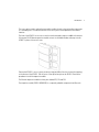
M
AP-6511 Access Point
Installation Guide
MOTOROLA and the Stylized M Logo are registered in the US Patent & Trademark Office. Symbol is a registered trademark of Symbol Technologies, Inc. All other product or service names are
the property of their respective owners. © Motorola, Inc. 2010. All rights reserved.
Table of Contents
1.0 Introduction . . . . . . . . . . . . . . . . . . . . . . . . . . . . . . . . . . . . . . . . . 1
1.1 Document Conventions . . . . . . . . . . . . . . . . . . . . . . . . . . . . . . . . . 1
1.2 Warnings . . . . . . . . . . . . . . . . . . . . . . . . . . . . . . . . . . . . . . . . . . . . 1
1.3 Site Preparation . . . . . . . . . . . . . . . . . . . . . . . . . . . . . . . . . . . . . . . 2
1.4 Package Contents . . . . . . . . . . . . . . . . . . . . . . . . . . . . . . . . . . . . . . 2
1.5 Features. . . . . . . . . . . . . . . . . . . . . . . . . . . . . . . . . . . . . . . . . . . . . . 2
2.0 Hardware Installation. . . . . . . . . . . . . . . . . . . . . . . . . . . . . . . . . 4
2.1 Installation Instructions . . . . . . . . . . . . . . . . . . . . . . . . . . . . . . . . . 4
2.2 Precautions . . . . . . . . . . . . . . . . . . . . . . . . . . . . . . . . . . . . . . . . . . . 4
2.3 Access Point Placement . . . . . . . . . . . . . . . . . . . . . . . . . . . . . . . . . 5
2.4 Power Injector System . . . . . . . . . . . . . . . . . . . . . . . . . . . . . . . . . . 5
2.5 Wall Mount Installation . . . . . . . . . . . . . . . . . . . . . . . . . . . . . . . . . 6
2.6 Telco Box Installation . . . . . . . . . . . . . . . . . . . . . . . . . . . . . . . . . . . 9
2.7 AP-6511 Antennas . . . . . . . . . . . . . . . . . . . . . . . . . . . . . . . . . . . . 14
2.8 LED Indicators . . . . . . . . . . . . . . . . . . . . . . . . . . . . . . . . . . . . . . . . 14
3.0 Defining a Basic AP-6511 Configuration . . . . . . . . . . . . . . . 15
4.0 Specifications . . . . . . . . . . . . . . . . . . . . . . . . . . . . . . . . . . . . . . 29
4.1 Electrical Characteristics . . . . . . . . . . . . . . . . . . . . . . . . . . . . . . . 29
4.2 Physical Characteristics . . . . . . . . . . . . . . . . . . . . . . . . . . . . . . . . 29
4.3 Radio Characteristics . . . . . . . . . . . . . . . . . . . . . . . . . . . . . . . . . . .30
5.0 Regulatory Information. . . . . . . . . . . . . . . . . . . . . . . . . . . . . . . .31
6.0 Motorola’s Enterprise Mobility Support Center . . . . . . . . . .41
Introduction
1
Introduction
The AP-6511 Access Point, a component of Motorola’s Wireless Controller System, links wireless
802.11a/b/g/n devices to the controller, enabling the growth of your wireless network with a
cost-effective alternative to standard access points.
The AP-6511 is an enterprise class 802.11n access point, installed in minutes anywhere a CAT-5 (or
better) cable is located. The AP-6511’s mechanical design is optimized for installation over a standard
CAT-5 (or better) wall jack. The AP does not protrude into the wall cavity, allowing for an efficient heat
transfer and a universal installation over a standard Telco wiring plate. The AP-6511’s modular design
allows the end-user to add switched Ethernet ports as-needed, and attach a standard keystone or
Leviton QuickPort® modular connector to the wall plate.
The AP-6511 access point ships with a single dual-band radio supporting the 802.11a/b/g/n radio
bands.
The AP6511 receives all power and transfers data through the same CAT-5 or better Ethernet cable.
There is no additional power supply required. An 802.3af PoE Ethernet switch or mid span power
injector is required.
The AP-6511 can be ordered for US deployment (AP-6511-60010-US) or ordered for deployment
outside of the US (AP-6511-60010-WR).
1.1 Document Conventions
The following graphical alerts are used in this document to indicate notable situations:
NOTE
!
Tips, hints, or special requirements that you should take note of.
CAUTION
WARNING!
Care is required. Disregarding a caution can result in data loss or
equipment malfunction.
Indicates a condition or procedure that could result in personal injury or
equipment damage.
1.2 Warnings
•
Read all installation instructions and site survey reports, and verify correct equipment
installation before connecting the AP-6511 access point.
1
2 AP-6511 Access Point Installation Guide
•
•
Verify any device connected to this unit is properly wired and grounded.
Verify there is adequate ventilation around the device, and ambient temperatures meet
equipment operation specifications.
1.3 Site Preparation
•
•
•
•
•
•
Consult your site survey and network analysis reports to determine specific equipment
placement, power drops etc.
Assign installation responsibility to the appropriate personnel.
Identify and document where all installed components are located.
Ensure adequate, dust-free ventilation to all installed equipment.
Prepare Ethernet port connections.
Verify cabling is within the maximum 100 meter allowable length.
1.4 AP-6511 Package Contents
The AP-6511 model access point ships with internal (integrated) antennas.
•
•
•
•
•
•
AP-6511 Access Point
Mounting plate (used for both wall mount and Telco Box installations)
Mounting plate lock screw
AP-6511 Installation Guide (This Guide)
RJ-45 double plug interconnect cable
Fast Ethernet port 1 interconnect cable
1.5 Features
•
•
•
•
One RJ-45 PoE Ethernet port (built into the AP-6511 access point)
Optional second RJ-45 Ethernet port utilizing a pass through (keystone) cable (included)
Optional three port Ethernet expansion module (sold separately)
2 LED indicators
The pass through (keystone) cable provides an option to add a second Ethernet port before installing
the AP-6511.
The AP-6511 has one RJ-45 connector supporting an 10/100 Ethernet port and requires 802.3af
compliant power from an external source.
The AP-6511 ships with a single dual-band radio supporting the 802.11a/b/g/n radio bands.
Introduction
The access point contains runtime firmware which enables the unit to boot after either a power up
or a watchdog reset. The runtime firmware on the access point can be updated via the Ethernet
interface.
The front of the AP-6511 has an access cover that can be removed to expose an additional connector.
A three port RJ-45 Ethernet expansion module connects to the hidden header and snaps onto the
AP-6511 in place of the access cover.
Remove the AP-6511’s access cover by inserting a long pointed tool into the circular hole (opening)
on the bottom of the AP-6511. Pull the access cover up and away from the AP-6511. Reverse the
procedure to install the expansion module.
The Ethernet expansion module has three ports labeled FE2, FE3 and FE4.
The expansion module (KT-6511-0000D-WR) is a separately orderable component from Motorola.
3
4 AP-6511 Access Point Installation Guide
2
Hardware Installation
2.1 Installation Instructions
An AP-6511 access point mounts either on a wall, under a table or over a Telco Box. The AP-6511 is
not plenum rated.
NOTE
The provided metal mounting plate is fastened to an existing standard
Telco in-wall box. The box is customer provided within the customer
building structure, and can be either plastic or metal in composition.
Screws and other mounting hardware are not included.
The AP-6511 is mounted to a wall or Telco Box so the mounting plate is flush with the mounting
surface.
The AP-6511 snaps on to the mounting plate without the use of tools or fastening hardware. Removal
of the AP-6511 from the mounting plate can be accomplished without the use of a tool. A mounting
lock screw is provided to help ensure a tamper resistant installation.
NOTE
Once installed onto the mounting plate, the assembly can resist a
minimum of 10 lbs of force before unit breakage or accidental
disassembly.
To prepare for an AP-6511 installation, perform the following:
1. Verify the contents of the box includes the intended AP-6511 access point model and
accessory hardware.
2. Review site survey and network analysis reports to determine the location and mounting
position for the AP-6511 access point.
3. Connect a CAT-5 or better Ethernet cable to a PoE compatible device and run the cable to the
installation site. Ensure there is sufficient cable slack to perform the installation steps.
2.2 Precautions
Before installing an AP-6511 access point:
•
•
Verify the intended AP-6511 deployment location is not prone to moisture or dust.
Verify the environment has a continuous temperature range between 0° C to 40° C.
Hardware Installation
2.3 Access Point Placement
For optimal performance, install the access point away from transformers, heavy-duty motors,
fluorescent lights, microwave ovens, refrigerators and other industrial equipment. Signal loss can
occur when metal, concrete, walls or floors block transmission. Install the access point in an open
area or add access points as needed to improve coverage.
To maximize the access point’s radio coverage area, Motorola recommends conducting a site survey
to define and document radio interference obstacles before installing the access point.
2.4 Power Injector System
When users purchase a WLAN solution, they often need to place access points in obscure locations.
In the past, a dedicated power source was required for each access point in addition to the Ethernet
infrastructure. This often required an electrical contractor to install power drops at each access point
location. The Power Injector merges power and Ethernet into one cable, reducing the burden of
installation and allowing optimal access point placement in respect to the intended coverage area.
A Motorola Power Injector (AP-PSBIAS-2P2-AFR) is recommended as the 802.3af compatible power
supply for the AP-6511. The Power Injector is capable of providing 12.95 Watts up to 100 meters. The
Power Injector is separately ordered and not shipped with the AP-6511. A separate Power Injector is
required for each access point comprising the network.
The Power Injector has no On/Off power switch. The Injector receives power and is ready for device
connection and operation as soon as AC power is applied. Refer to the Installation Guide shipped with
the Power Injector for a description of the device’s LEDs.The Power Injector can be installed free
standing, on an even horizontal surface or wall mounted using the Power Injector’s wall mounting key
holes.
The following guidelines should be adhered to before cabling the Power Injector to an Ethernet source
and an access point:
•
•
•
Do not block or cover airflow to the Power Injector.
Keep the Power Injector away from excessive heat, humidity, vibration and dust.
The Power Injector isn’t a repeater, and does not amplify the Ethernet signal. For optimal
performance, ensure the Power Injector is placed as close as possible to the Ethernet
switch. This will allow the AP-6511 to be deployed away from power drops.
5
6 AP-6511 Access Point Installation Guide
•
!
!
Ensure the cable length from the Ethernet source (host) to the Power Injector and AP-6511
access point does not exceed 100 meters (333 ft).
CAUTION
To avoid problematic performance and restarts, disable POE from a
wired controller port connected to an access point if mid-span power
sourcing equipment (PSE) is used between the two, regardless of the
manufacturer.
CAUTION
Ensure AC power is supplied to the Power Injector using an AC cable
with an appropriate ground connection approved for the country of
operation.
2.5 Wall Mount Installation
To support wall mount installations, the metal mounting plate (provided with the AP-6511) is fastened
to a flat wall surface. The wall should be of gypsum board, plaster, wood or concrete in composition.
NOTE
Motorola recommends the following customer supplied mounting
accessories an AP-6511 wall mount installation:
2, screws, #6 x 2.00 inch pan head
2, wall anchors suitable for the #6 screws
To install an AP-6511 model access point to a wall surface:
1. Attach the metal mounting plate (shipped with the AP-6511) to a wall surface at the desired
deployment location.
Hardware Installation
The screws used to mount the bracket are customer provided and should be #6, with a 2.00
inch length.
2. Connect one end of an RJ-45 cable into the wall mount connector on the AP-6511 as
illustrated below.
7
8 AP-6511 Access Point Installation Guide
3. If using the optional second RJ-45 Ethernet port (utilizing a pass through keystone cable),
ensure the following steps are completed:
a. Bend the cable into a “U” shape so the mini pin connector and the RJ-45 keystone cable
are in close proximity to one another.
b. Install the mini pin connector into the pin socket on the back of the AP-6511. The
connector is keyed and can only be installed one way. Ensure the mini pin connector is
connected securely.
c. Remove the blank plug from the keystone hole by gently pushing it out from the back.
d. Orient the RJ-45 keystone connector so the flexible keystone tab is away from the mini
pin connector. Tip the keystone RJ-45 while installing in the keystone opening so the
solid locking tabs engage, then rotate the RJ-45 forward until the tab snaps securely.
4. Snap the AP-6511 on to the mounted wall plate. Use the locking screw to secure the unit.
This connection does not require the use of tools or fastening hardware.
Once installed, connections are hidden from forward view, with only the physical
infrastructure cables (Ethernet and power) extending from the AP-6511.
Hardware Installation
5. Cable the access point using a Power Injector solution (AP-PSBIAS-2P2-AFR) as described in
the following:
a. Connect an RJ-45 CAT5 Ethernet cable between the network data supply (host) and the
Power Injector’s Data In connector.
b. Connect an RJ-45 CAT5 Ethernet cable between the Power Injector’s Data & Power Out
connector and the AP-6511 access point.
c. Ensure the cable length from the Ethernet source (host) to the Power Injector and access
point does not exceed 100 meters (333 ft). The Power Injector has no On/Off power
switch. The Power Injector receives power as soon as AC power is applied. For more
information, see “Power Injector System” on page 5.
6. Verify the behavior of the AP-6511 access point LEDs. For more information, see “LED
Indicators” on page 14.
7. The AP-6511 is ready to configure. For information on basic access point device
configuration, see “Defining a Basic AP-6511 Configuration” on page 15.
2.6 Telco Box Installation
For Telco Box installations, the AP-6511 is installed directly over the standard wall plate supplying
Ethernet. All cabled electrical connections are mode within a recessed well in the housing of the
AP-6511 access point.
To install the AP-6511 access point over a Telco Box:
9
10 AP-6511 Access Point Installation Guide
1. Remove the cover of the CAT5 wall plate.
NOTE
The example above assumes the Telco Box has a 1 RJ11 phonejack and
1 RJ-45 10/100 Ethernet connection.
2. Snap out keystone connectors from existing plate.
Hardware Installation
3. Gently pull some cable out of the wall so it can be used with the AP-6511 access point.
4. Attach the metal mounting plate (shipped with the AP-6511) to an existing standard Telco
in-wall box.
The screws used to mount the bracket to the Telco Box are customer provided. You can use
the same screws that covered the existing wall plate if necessary.
Mount the bracket to the wall so the Telco Box is ready available behind the mounting plate.
5. Remove the blank plug before installing the RJ11 into the snap-in port.
11
12 AP-6511 Access Point Installation Guide
6. Install the RJ11 (keystone style) connector into the AP-6511’s snap-in port.
To PBX
RJ45 connector
7. If using the optional second RJ-45 Ethernet port (utilizing a pass through keystone cable),
ensure the following steps are completed:
a. Bend the cable into a “U” shape so the mini pin connector and the RJ-45 keystone cable
are in close proximity to one another.
b. Install the mini pin connector into the pin socket on the back of the AP-6511. The
connector is keyed and can only be installed one way. Ensure the mini pin connector is
connected securely.
c. Remove the blank plug from the keystone hole by gently pushing it out from the back.
d. Orient the RJ-45 keystone connector so the flexible keystone tab is away from the mini
pin connector. Tip the keystone RJ-45 while installing in the keystone opening so the
solid locking tabs engage, then rotate the RJ-45 forward until the tab snaps securely.
8. Install the RJ-45 double plug uplink jumper into the UP1/POE jack and connect it into the
RJ-45 Ethernet connector.
Hardware Installation
9. Snap the AP-6511 on to the mounted wall plate and secure the AP-6511 using the mounting
plate lock screw. This connection does not require the use of tools or fastening hardware.
Once installed, no cables extend from the AP-6511 since they are hidden from view within
the Telco Box.
10. Cable the access point using a Power Injector solution (AP-PSBIAS-2P2-AFR) as described in
the following:
a. Connect an RJ-45 CAT5 Ethernet cable between the network data supply (host) and the
Power Injector’s Data In connector.
b. Connect an RJ-45 CAT5 Ethernet cable between the Power Injector’s Data & Power Out
connector and the AP-6511 access point.
c. Ensure the cable length from the Ethernet source (host) to the Power Injector and access
point does not exceed 100 meters (333 ft). The Power Injector has no On/Off power
switch. The Power Injector receives power as soon as AC power is applied. For more
information, see “Power Injector System” on page 5.
11. Verify the behavior of the AP-6511 access point LEDs. For more information, see “LED
Indicators” on page 14.
12. The AP-6511 is ready to configure. For information on basic access point device
configuration, see “Defining a Basic AP-6511 Configuration” on page 15.
13
14 AP-6511 Access Point Installation Guide
2.7 AP-6511 Antennas
The AP-6511 model access point contains two internal (embedded) dual-band antennas supporting
both the 802.11b/g/n (2.4 GHz) and 802.11a/n (5.0 GHz) bands. No customer assembly or antenna
orientation is required.
The AP-6511 radio can transmit on one or two antennas depending on the operating modes. The radio
can receive on one or two antennas as well. The data rates supported are different in each case.
2.8 LED Indicators
An AP-6511 model access point has two LED activity indicators on the front of the unit.
The LEDs provide a status display indicating error conditions, transmission, and network activity for
the 5 GHz 802.11a/n (amber) radio or the 2.4 GHz 802.11b/g/n (green) radio.
Task
5 GHz Activity LED (Amber)
2.4 GHz Activity LED (Green)
Unadopted
Off
Blinking 5 times per second
Normal
Operation
• If this radio band is enabled:
Blink at 5 second interval
• If this radio band is disabled:
Off
• If there is activity on this band:
Blink at a 1Hz
• If this radio band is enabled:
Blink at 5 second interval
• If this radio band is disabled:
Off
• If there is activity on this band:
Blink at a 1Hz
Firmware
Update
On
Off
Locate AP
Mode
Blink at 5Hz
(Out of Phase with Activity LED)
Blink at 5Hz
(Out of Phase with Activity LED)
Defining a Basic AP-6511 Configuration
3
Defining a Basic AP-6511 Configuration
Once the access point is installed and powered on, complete the following steps to get the device up
and running using the Initial Setup Wizard and access the AP-6511’s management functions:
1. Connect one end of an Ethernet cable to the PoE port on the back of the AP-6511. Connect
the other end to a computer with a functional Web browser. Use a power injector as needed
to consolidate power and Ethernet in one cable (for more information, see “Power Injector
System” on page 5).
If your host system is a DHCP server, an IP address is automatically assigned to the AP-6511
and can be used for device connection. However, if a DHCP server is not available, you’ll
need to derive the IP address from the AP-6511 MAC address. Using this method, the last
two hex bytes of the AP-6511 MAC address become the last two octets of the IP address.
AP-6511 MAC address - 00:C0:23:00:F0:0A
AP-6511 IP address equivalent - 169.254.240.10
To derive the AP-6511’s IP address using its factory assigned MAC address:
a. Open the Windows calculator be selecting Start > All Programs > Accessories >
Calculator. This menu path may vary slightly depending on your version of Windows.
b. With the Calculator displayed, select View > Scientific. Select the Hex radio button.
c. Enter a hex byte of the AP-6511’s MAC address. For example, F0.
d. Select the Dec radio button. The calculator converts F0 into 240. Repeat this process for
the last AP-6511 MAC address octet.
2. Point the Web browser to the AP-6511’s IP address. The following login screen displays.
15
16 AP-6511 Access Point Installation Guide
3. Enter the default username admin in the Username field.
4. Enter the default password motorola in the Password field.
5. Select the Login button to load the management interface.
If this is the first time the management interface has been accessed, you are prompted to
change the default password, and a dialogue displays to start the Initial Setup Wizard.
6. Select the Start Wizard button to run the initial setup wizard.
The setup wizard displays the first time the AP-6511 user interface is accessed in order to
define the AP-6511’s configuration.
Once these settings have been defined, and the AP-6511 has successfully been deployed or
adopted by a Controller AP, the Initial Setup Wizard no longer displays in subsequent logins.
NOTE
When navigating the Initial Setup Wizard, the left-hand side of the
Wizard can either display a topology Diagram or an Event Log of the
tasks completed or failed during the AP-6511 configuration. Motorola
recommends periodically reviewing the topology and log to assess
whether the tasks completed thus far have satisfied their intended
AP-6511 deployment requirements. Once the tasks within the Initial
Setup Wizard are completed, the user can navigate within the AP-6511
user interface to complete a broader range of configuration activities. For
advanced configuration information beyond the scope of this AP-6511
Installation Guide, refer to the Motorola Wireless Services Controller
System Reference Guide, available at
http://support.symbol.com/support/product/manuals.do.
Defining a Basic AP-6511 Configuration
7. Set the AP-6511 Access Point Type. The following options are available:
• Controller AP - When more than one AP-6511 is deployed, a single AP-6511 can function
as a Controller AP to manage Dependent mode AP-6511s. Up to 24 Dependant APs can
be connected to a Controller AP.
• Standalone AP - Select this option to deploy this AP-6511 as an autonomous access
point.
• Dependent AP - Select this option when deploying the AP-6511 as a Controller AP
managed access point. Selecting this option closes the Initial Setup Wizard. A
Dependant AP obtains its configuration from a profile stored on the Controller AP. Any
manual configuration changes on a Dependant AP are overwritten by the Controller AP
upon reboot. A Dependent AP requires a Controller AP in the network.
8. Select Next to continue.
The Initial Setup Wizard displays the System Information screen for setting administrative
credentials and device access protocols.
17
18 AP-6511 Access Point Installation Guide
9. Change the default Password and enter a Location and Contact name
Changing the default password is critical before any configuration customizations are made
to protect the data exchanged between the AP-6511 and its peers. Ensure the Location
represents the AP-6511’s deployment area and the Contact accurately reflects the
administrator responsible for this AP-6511 access point.
10. Set a Time Zone and Country.
Both the Time Zone and Country should reflect the actual deployment credentials of this
AP-6511, to best assist in any troubleshooting of the device that may be needed.
11. Select any or all of access methods (HTTP, HTTPS, Telnet or SSHv2) used for connecting to
this AP-6511 access point.
12. Select the Next button to continue to the Topology Selection screen.
Defining a Basic AP-6511 Configuration
13. Make a Topology Selection based on your network’s configuration. The selected topology
mode determines which options display in the remainder of the Initial Setup Wizard.
• Router Mode - In Router Mode, the AP-6511 routes traffic between the local network
(LAN) and internet or external network (WAN).
• Bridge Mode - In Bridge Mode, the AP-6511 depends on an external router for routing
LAN and WAN traffic. Routing is generally used on one device, whereas bridging is
typically used for a larger density network.
For the purposes of this guide, Router Mode is selected, as Bridge Mode does not require
that all parameters be set.
19
20 AP-6511 Access Point Installation Guide
14. Select Next to continue to the LAN Configuration screen.
The LAN Configuration screen is partitioned into LAN Interface, DHCP Address
Assignment and Domain Name Server (DNS) fields.
15. Set the following LAN Interface information:
• LAN IP Address/Subnet - Enter an IP Address and a subnet for the AP-6511’s LAN
interface. If the Use DHCP checkbox is selected, this field is not available.
• Use DHCP - Select the checkbox to enable an automatic network configuration using a
DHCP server. If this option is enabled, the LAN IP Address/Subnet, DHCP Address
Assignment and Domain Name fields are populated by the DHCP server.
• What VLAN ID should be used for the LAN interface? - Use the spinner to select the
VLAN ID to associate with the LAN Interface. The default setting is VLAN 1.
Defining a Basic AP-6511 Configuration
• Configure VLANs Manually - Select the checkbox to enable an advanced manual VLAN
configuration.
• Advanced VLAN Configuration - Select the Advanced VLAN Configuration button to set
associations between VLANs and physical interfaces. Selecting this option displays a
screen for editing the tagging, trunking and VLAN assignments for each AP-6511 port.
16. Set the following DHCP Address Assignment information:
• Use the Controller to assign IP addresses to devices -Select the checkbox to enable the
onboard DHCP server to provide IP and DNS information to clients on the LAN interface.
• IP Address Range - Enter a starting and ending IP Address range for client assignments
on the LAN interface. Avoid assigning IP addresses from x.x.x.1 - x.x.x.10 and x.x.x.255
as they are often reserved for standard network services.
17. Set the following Domain Name Server information:
• Primary DNS - Enter an IP Address for the main Domain Name Server providing DNS
services for the LAN interface.
• Secondary DNS - Enter an IP Address for the backup Domain Name Server providing DNS
services for the LAN interface.
18. Select Next to continue to the WAN Configuration screen.
The WAN Configuration screen is partitioned into WAN Interface and Gateway fields.
21
22 AP-6511 Access Point Installation Guide
19. Set the following WAN Interface information:
• WAN IP Address/Subnet - Enter an IP Address and a subnet for the AP-6511’s WAN
interface. If the Use DHCP checkbox is selected, this field is not available.
• Use DHCP - Select the checkbox to enable an automatic network configuration using a
DHCP server. If this option is enabled, the WAN IP Address/Subnet and Gateway fields
are populated by the DHCP server.
• What VLAN ID should be used for the WLAN interface? - Use the spinner to select the
VLAN ID to associate with the WAN Interface. The default setting is VLAN 2100.
• What port is connected to the external network? - Use the drop-down menu to select the
physical port that’s connected to the WAN interface.
• Enable NAT on the WAN Interface - Select the checkbox to allow traffic to pass between
the WAN and LAN interfaces.
20. Enter an IP Address for the AP-6511’s Default Gateway on the WAN interface. If the Use
DHCP checkbox is enabled, this field is not configurable.
21. Select Next to continue to the WLAN Setup screen.
Defining a Basic AP-6511 Configuration
22. Use the WLAN Setup screen to set the WLAN configurations used on the AP-6511. To add
a new WLAN, select Add WLAN or select an existing WLAN to modify from those listed.
Set the following parameters for the new or modified WLAN configuration:
• SSID - Enter or modify the Services Set Identification (SSID) associated with the WLAN.
The WLAN name is auto-generated using the SSID until changed by the user. The
maximum number of characters is 32. Do not use < > | " & \ ? ,
• WLAN Type - Select either No authentication, no encryption (for an insecure WLAN),
Captive portal authentication, no encryption (for a guest WLAN), PSK authentication,
WPA2 encryption (to implement a pre shared key) or EAP authentication, WPA2
encryption (to implement an external RADIUS server).
• VLAN ID - Use the drop-down menu to select a VLAN for traffic segregation on this
WLAN. All configured VLANs are available.
• WPA Key - Enter an alphanumeric string of 8 to 63 ASCII characters or 64 HEX characters
as the primary string both transmitting and receiving authenticators must share if using
a pre shared key. The alphanumeric string allows character spaces. This passphrase
saves the administrator from entering the 256-bit key each time keys are generated.
23. Select OK to save the changes and exit. Select Next to display the RADIUS
Authentication screen.
23
24 AP-6511 Access Point Installation Guide
24. Use the RADIUS Authentication screen to define an external RADIUS server configuration
utilized by the AP-6511 when an external authentication source is required for an WLAN.
• RADIUS Server - Provide either the numerical IP address or hostname of the external
RADIUS resource used to validate AP-6511 WLAN access.
• RADIUS Shared Secret - Specify a Shared Secret for authenticating RADIUS requests to
access a AP-6511 managed WLAN. Shared secrets verify RADIUS messages from
RADIUS enabled devices configured with the same secret passphrase.
25. Select Commit/Next to save the updates to the RADIUS Authentication screen and display
the AP Discovery screen.
The AP Discovery screen lists access points discovered by this AP-6511. It displays their
Hostname, MAC Address and Serial Number. If you have connected to any APs recently,
select Refresh List to update the list of known APs.
Defining a Basic AP-6511 Configuration
Use the Hostname parameter to optionally define names for the access points discovered
by this AP-6511. Defining hostnames is a good practice to differentiate discovered APs with
similar configurations.
26. Select Next to continue to the Wireless Client Association screen.
The Wireless Client Association screen displays adopted wireless clients and the
AP-6511 WLANs they are currently connected to.
25
26 AP-6511 Access Point Installation Guide
27. To verify the WLAN’s configuration, associate a client with each configured WLAN. After
associating, click the Refresh button to update the list of associated wireless clients.
28. Select Save/Next to commit any changes made and continue to the Date and Time
screen.
Defining a Basic AP-6511 Configuration
Use the Date and Time screen to set the system time and time resource used by this
AP-6511.
29. Either refer to the System Date and Time parameter to manually set the system time, or
use the recommended Network Time Protocol (NTP) parameter to define an external
NTP server resource to periodically synchronize system time with this AP-6511.
If manually providing system time, select the Update Clock button to commit the system
time to the AP-6511. If using an external NTP resource, provide its numerical IP address and
select the Update NTP button.
30. Select Finish to complete the AP-6511 Initial Setup Wizard. Once complete, a configuration
profile is created and assigned to the AP-6511.
27
28 AP-6511 Access Point Installation Guide
In addition to the Diagram and Event Log tabs available thus far, a Complete tab displays
confirming the completion of the Initial Setup Wizard. The Complete tab lists the changes
made to the user interface to configure the AP-6511.
The Complete tab lists the user interface Screens and Settings modified by the updates
made to the AP-6511 configuration using the Initial Setup Wizard. Scroll to any screen listed
within the Complete tab to display that screen within the AP-6511 user interface if
additional modifications are required beyond the scope of the Initial Setup Wizard.
For advanced configuration information beyond the scope of this AP-6511 Installation Guide,
refer to the Motorola Wireless Services Controller System Reference Guide, available at
http://support.symbol.com/support/product/manuals.do.
Specifications
4
Specifications
4.1 Electrical Characteristics
An AP-6511 model access point has the following electrical characteristics:
Operating Current &
Voltage
250mA@48VDC
4.2 Physical Characteristics
An AP-6511 model access point has the following physical characteristics:
Dimensions
2.75 width x 5 height x 1.25 deep (Inches)
6.985 width x 12.7 height x 3.175 deep (centimeters)
Housing
Plastic and metal
Weight
0.5 lbs (with mounting plate)
Operating
Temperature
32°F to 104°F/0°C to 40°C
Storage Temperature
-40°F to 158°F/-40°C to 70°C
Operating Humidity
5 to 95% Relative Humidity non-condensing
Storage Humidity
95% Relative Humidity non-condensing
Operating Altitude
(max)
8,000 ft @ 28°C
Storage Altitude
(max)
30,000 ft @ 12°C
Electrostatic
Discharge
+/-8kV Air and +/-8kV Contact @ 50% Relative Humidity
29
30 AP-6511 Access Point Installation Guide
4.3 Radio Characteristics
An AP-6511 model access point has the following radio characteristics:
Operating Channels
All channels from 5180 MHz to 5825 MHz
Channels 1-13 (2412-2472 MHz)
Actual operating frequencies depend on regulatory approval for the
country of use.
Data Rates Supported 802.11b: 1Mbps, 2Mbps, 5.5Mbps and 11Mbps
802.11g: 6Mbps, 9Mbps, 12Mbps, 18Mbps, 24Mbps, 36MBps,
48Mbps and 54Mbps
802.11n: MCS0 through MCS15, HT20 and HT40
Wireless Medium
Direct Sequence Spread Spectrum (DSSS),
Orthogonal Frequency Division Multiplexing (OFDM)
Spatial multiplexing (MIMO)
Network Standards
802.11a, 802.11b, 802.11g, 802.3, 802.11n
Typical Transmit
Power Per Antenna
2.4G: +24dBm max
5.2G: +22dBm max
Transmit Power
Adjustment
1dB increments
Regulatory Information
5
Regulatory Information
5.1 Regulatory Overview
This device is approved under the Motorola brand.
This guide applies to Model Number AP-6511.
All Motorola/Symbol devices are designed to be compliant with rules and regulations in locations
they are sold and will be labeled as required.
Local language translations are available at the following website: http://support.symbol.com
Any changes or modifications to Motorola/Symbol Technologies equipment, not expressly approved
by Motorola/Symbol Technologies, could void the user’s authority to operate the equipment.
Motorola/Symbol Access Points must be professionally installed and configured so that the Radio
Frequency Output Power will not exceed the maximum allowable limit for the country of operation.
Antennas: Use only the supplied or an approved replacement antenna. Unauthorized antennas,
modifications, or attachments could cause damage and may violate regulations. Use of an
unapproved antenna is illegal under FCC regulations subjecting the end user to fines and equipment
seizure.
5.2 Wireless Device Country Approvals
Regulatory markings, subject to certification, are applied to the device signifying the radio(s) is/are
approved for use in the following countries: United States, Canada, Japan, China, S. Korea, Australia,
and Europe.
Please refer to the Declaration of Conformity (DoC) for details of other country markings. This is
available at
http://www.motorola.com/Business/US-EN/Document+Library/Declaration+of+Conformity
Note: For 2.4GHz or 5GHz Products: Europe includes, Austria, Belgium, Bulgaria, Czech Republic,
Cyprus, Denmark, Estonia, Finland, France, Germany, Greece, Hungary, Iceland, Ireland, Italy, Latvia,
Liechtenstein, Lithuania, Luxembourg, Malta, Netherlands, Norway, Poland, Portugal, Romania,
Slovak Republic, Slovenia, Spain, Sweden, Switzerland and the United Kingdom.
Operation of the device without regulatory approval is illegal.
31
32 AP-6511 Access Point Installation Guide
5.2.1 Country Selection – Note for AP & Wireless Controller
Select only the country in which you are using the device. Any other selection will make the operation
of this device illegal. The US version of the Access Point will only have US listed in the country
selection table. The US version will be sold / used in the US protectorates: American Samoa, Guam,
Puerto Rico, US Virgin Islands.
5.2.2 Frequency of Operation – FCC and IC
5 GHz Only
The use on UNII (Unlicensed National Information Infrastructure) Band 1 5150-5250 MHz and Band 3
5470 - 5725 MHz is restricted to indoor use only, any other use will make the operation of this device
illegal.
Devices using the 5470 – 5725 MHz band shall not be capable of transmitting in the band 5600 - 5650
MHz in the US, this “Notched” band has been disabled in the US version of the Access Point.
2.4 GHz Only
The available channels for 802.11 b/g operation in the US are Channels 1 to 11. The range of channels
is limited by firmware.
5.3 Health and Safety Recommendations
5.3.1 Warnings for the use of Wireless Devices
Please observe all warning notices with regard to the usage of wireless devices
5.3.2 Potentially Hazardous Atmospheres – Fixed Installations
You are reminded of the need to observe restrictions on the use of radio devices in fuel depots,
chemical plants etc. and areas where the air contains chemicals or particles (such as grain, dust, or
metal powders).
5.3.3 Safety in Hospitals
Wireless devices transmit radio frequency energy and may affect medical electrical equipment.
When installed adjacent to other equipment, it is advised to verify that the adjacent equipment is not
adversely affected.
Regulatory Information
Pacemakers
Pacemaker manufacturers recommended that a minimum of 15cm (6 inches) be maintained between
a handheld wireless device and a pacemaker to avoid potential interference with the pacemaker.
These recommendations are consistent with independent research and recommendations by
Wireless Technology Research.
Persons with Pacemakers:
•
•
•
•
Should ALWAYS keep the device more than 15cm (6 inches) from their pacemaker when
turned ON.
Should not carry the device in a breast pocket.
Should use the ear furthest from the pacemaker to minimize the potential for interference.
If you have any reason to suspect that interference is taking place, turn OFF your device.
Other Medical Devices
Please consult your physician or the manufacturer of the medical device, to determine if the operation
of your wireless product may interfere with the medical device.
5.4 RF Exposure Guidelines
5.4.1 Safety Information
Reducing RF Exposure—Use Properly
Only operate the device in accordance with the instructions supplied.
5.5 International
The device complies with internationally recognized standards covering human exposure to
electromagnetic fields from radio devices. For information on “International” human exposure to
eletromagnic fields refer to the Motorola/Symbol Declaration of Conformity (DoC) at
http://www.motorola.com/Business/US-EN/Document+Library/Declaration+of+Conformity
5.6 EU
Remote and Standalone Antenna Configurations
To comply with EU RF exposure requirements, antennas that are mounted externally at remote
locations or operating near users at stand-alone desktop of similar configurations must operate with
a minimum separation distance of 20 cm from all persons.
33
34 AP-6511 Access Point Installation Guide
5.7 US and Canada
Co-located statement
To comply with FCC RF exposure compliance requirement, the antennas used for this transmitter must
not be co-located or operating in conjunction with any other transmitter/antenna except those
already approved in this filling.
Remote and Standalone Antenna Configurations
To comply with FCC RF exposure requirements, antennas that are mounted externally at remote
locations or operating near users at stand-alone desktop of similar configurations must operate with
a minimum separation distance of 20 cm from all persons.
5.8 Power Supply
This device is powered from a 802.3af compliant power source which is UL approved and certified by
the appropriate agencies.
5.9 Radio Frequency Interference Requirements—FCC
This equipment has been tested and found to comply with the limits for a Class B
digital device, pursuant to Part 15 of the FCC rules. These limits are designed to
provide reasonable protection against harmful interference in a residential
installation. This equipment generates, uses and can radiate radio frequency energy
and, if not installed and used in accordance with the instructions, may cause harmful interference to
radio communications. However there is no guarantee that interference will not occur in a particular
installation. If this equipment does cause harmful interference to radio or television reception, which
can be determined by turning the equipment off and on, the user is encouraged to try to correct the
interference by one or more of the following measures:
•
•
•
Increase the separation between the equipment and receiver
Connect the equipment into an outlet on a circuit different from that to which the receiver
is connected
Consult the dealer or an experienced radio/TV technician for help
Radio Transmitters (Part 15)
This device complies with Part 15 of the FCC Rules. Operation is subject to the following two
conditions: (1) this device may not cause harmful interference, and (2) this device must accept any
interference received, including interference that may cause undesired operation.
Restricted Band 5.60 – 5.65 GHz
Regulatory Information
5.10 Radio Frequency Interference Requirements – Canada
This Class B digital apparatus complies with Canadian ICES-003.
Cet appareil numérique de la classe B est conforme à la norme NMB-003 du Canada.
5.10.1 Radio Transmitters
For RLAN Devices:
The use of 5 GHz RLAN’s, for use in Canada, have the following restrictions:
• Restricted Band 5.60 – 5.65 GHz
This device complies with RSS 210 of Industry & Science Canada. Operation is subject to the
following two conditions: (1) this device may not cause harmful interference and (2) this device must
accept any interference received, including interference that may cause undesired operation.
Label Marking: The Term "IC:" before the radio certification only signifies that Industry Canada
technical specifications were met.
5.11 CE Marking and European Economic Area (EEA)
The use of 2.4 GHz RLAN’s, for use through the EEA, have the following restrictions:
•
•
•
Maximum radiated transmit power of 100 mW EIRP in the frequency range 2.400 -2.4835
GHz.
France, outside usage is restricted to 2.4 – 2.454 GHz.
Italy requires a user license for outside usage.
5.12 Statement of Compliance
Motorola/Symbol hereby, declares that this device is in compliance with the essential requirements
and other relevant provisions of Directive 1999/5/EC. A Declaration of Conformity may be obtained
from http://www.motorola.com/Business/US-EN/Document+Library/Declaration+of+Conformity.
35
36 AP-6511 Access Point Installation Guide
5.13 Waste Electrical and Electronic Equipment (WEEE)
English: For EU Customers: All products at the end of their life must be returned to Symbol for
recycling. For information on how to return product, please go to:
http://www.symbol.com/environmental_compliance.
Dansk: Til kunder i EU: Alle produkter skal returneres til Symbol til recirkulering, når de er
udtjent. Læs oplysningerne om returnering af produkter på: http://www.symbol.com/
environmental_compliance.
Deutsch: Für Kunden innerhalb der EU: Alle Produkte müssen am Ende ihrer Lebensdauer zum
Recycling an Symbol zurückgesandt werden. Informationen zur Rücksendung von Produkten
finden Sie unter http://www.symbol.com/environmental_compliance.
Eesti: EL klientidele: kõik tooted tuleb nende eluea lõppedes tagastada taaskasutamise
eesmärgil Symbol'ile. Lisainformatsiooni saamiseks toote tagastamise kohta külastage palun
aadressi: http://www.symbol.com/environmental_compliance.
Español: Para clientes en la Unión Europea: todos los productos deberán entregarse a Symbol
al final de su ciclo de vida para que sean reciclados. Si desea más información sobre cómo
devolver un producto, visite: http://www.symbol.com/environmental_compliance.
Français : Clients de l'Union Européenne : Tous les produits en fin de cycle de vie doivent être
retournés à Symbol pour recyclage. Pour de plus amples informations sur le retour de produits,
consultez : http://www.symbol.com/environmental_compliance.
Italiano: per i clienti dell'UE: tutti i prodotti che sono giunti al termine del rispettivo ciclo di
vita devono essere restituiti a Symbol al fine di consentirne il riciclaggio. Per informazioni sulle
modalità di restituzione, visitare il seguente sito Web: http://www.symbol.com/
environmental_compliance.
Magyar: Az EU-ban vásárlóknak: Minden tönkrement terméket a Symbol vállalathoz kell
eljuttatni újrahasznosítás céljából. A termék visszajuttatásának módjával kapcsolatos
tudnivalókért látogasson el a http://www.symbol.com/environmental_compliance weboldalra
Regulatory Information
Nederlands: Voor klanten in de EU: alle producten dienen aan het einde van hun levensduur
naar Symbol te worden teruggezonden voor recycling. Raadpleeg http://www.symbol.com/
environmental_compliance voor meer informatie over het terugzenden van producten.
Português: Para clientes da UE: todos os produtos no fim de vida devem ser devolvidos à
Symbol para reciclagem. Para obter informações sobre como devolver o produto, visite: http:/
/www.symbol.com/environmental_compliance.
Slovenski: Za kupce v EU: vsi izdelki se morajo po poteku življenjske dobe vrniti podjetju
Symbol za reciklažo. Za informacije o vraèilu izdelka obišèite: http://www.symbol.com/
environmental_compliance.
Suomi: Asiakkaat Euroopan unionin alueella: Kaikki tuotteet on palautettava kierrätettäväksi
Symbol-yhtiöön, kun tuotetta ei enää käytetä. Lisätietoja tuotteen palauttamisesta on
osoitteessa http://www.symbol.com/environmental_compliance.
5.14 TURKISH WEEE Statement of Compliance
EEE Yönetmeliğine Uygundur
5.15 Japan (VCCI) - Voluntary Control Council for Interference Class B
ITE
この装置は、情報処理装置等電波障害自主規制協議会 (VCCI)の基準に基づくク
ラス B 情報技術装置です。この装置は、家庭環境で使用することを目的としています
が、この装置がラジオやテレビジョン受信機に近接して使用されると、受信障害を引
き起こすことがあります。取扱説明書に従って正しい取り扱いをして下さい。
This is a Class B product based on the standard of the Voluntary Control Council for Interference from
Information Technology Equipment (VCCI). If this is used near a radio or television receiver in a
domestic environment, it may cause radio interference. Install and use the equipment according to
the instruction manual.
37
38 AP-6511 Access Point Installation Guide
5.16 Korea Warning Statement for Class B ITE
기종별
B 급 기기
( 가정용 방송통신기기 )
사용자안내문
이 기기는 가정용 (B 급 ) 으로 전자파적합등록을
한 기기로서 주로 가정에서 사용하는 것을 목적
으로 하며 , 모든 지역에서 사용할 수 있습니다 .
Class B (Broadcasting
This device obtained EMC registration mainly for home use
Communication Device for Home (Class B) and may be used in all areas.
Use)
5.17 Other Countries
5.17.1 Australia
Use of 5 GHz RLAN’s in Australia is restricted in the following band 5.50 – 5.65 GHz.
5.17.2 Brazil
Regulatory declarations for AP-6511 - BRAZIL
Note: The certification mark applied to the AP-6511 is for Restrict Radiation Equipment. This
equipment operates on a secondary basis and does not have the right for protection against harmful
interference from other users including same equipment types. Also this equipment must not cause
interference to systems operating on primary basis.
For more information consult the website http://www.anatel.gov.br
Declarações Regulamentares para AP-6511 - Brasil
Nota: "A marca de certificação se aplica ao Transceptor, modelo AP-650. Este equipamento opera em
caráter secundário, isto é, não tem direito a proteção contra interferência prejudicial, mesmo de
estações do mesmo tipo, e não pode causar interferência a sistemas operando em caráter primário.”
Para maiores informações sobre ANATEL consulte o site: http://www.anatel.gov.br
5.17.3 Chile
“Este equipo cumple con la Resolución No 403 de 2008, de la Subsecretaria de telecomunicaciones,
relativa a radiaciones electromagnéticas.”.
"This device complies with the Resolution Not 403 of 2008, of the Undersecretary of
telecommunications, relating to electromagnetic radiation.”
Regulatory Information
5.17.4 Mexico
Restrict Frequency Range to: 2.450 – 2.4835 GHz.
5.17.5 Taiwan
NOTICE!
According to: Administrative Regulations on Low Power Radio Waves Radiated Devices
Article 12
Without permission granted by the DGT, any company, enterprise, or user is not allowed to change
frequency, enhance transmitting power or alter original characteristic as well as performance to an
approved low power radio-frequency devices.
Article 14
The low power radio-frequency devices shall not influence aircraft security and interfere legal
communications; If found, the user shall cease operating immediately until no interference is
achieved.
The said legal communications means radio communications is operated in compliance with the
Telecommunications Act.
The low power radio-frequency devices must be susceptible with the interference from legal
communications or ISM radio wave radiated devices.
臺灣
低功率電波輻射性電機管理辦法
第十二條
經型式認證合格之低功率射頻電機,非經許可,公司、商號或使用者均不得擅自
變更頻率、加大功率或變更原設計之特性及功能。
第十四條
低功率射頻電機之使用不得影響飛航安全及干擾合法通信;經發現有干擾現象
時,應立即停用,並改善至無干擾時方得繼續使用。
前項合法通信,指依電信規定作業之無線電通信。
低功率射頻電機須忍受合法通信或工業、科學及醫療用電波輻射性電機設備之干
擾。
39
40 AP-6511 Access Point Installation Guide
Wireless device operate in the frequency band of 5.25-5.35 GHz, limited for Indoor use only.
在 5.25-5.35 赫頻帶內操作之無線資訊傳輸設備,限於室內使用。
5.17.6 Korea
For radio equipment using 2400~2483.5MHz or 5725~5825MHz, the following expressions should be
displayed:
1. “This radio equipment can be interfered with during operation.”
당해 무선설비는 운용 중 전파혼신 가능성이 있음
2. “This radio equipment cannot provide a service relevant to human life safety, as it can be
crossed” through the user manual, etc.
당해 무선설비 는전파혼 신 가능성이 있으므로 인명안전과 관련된 서비스는 할 수 없습니다
Motorola’s Enterprise Mobility Support
Center
6
Motorola’s Enterprise Mobility Support Center
If you have a problem with your equipment, contact Enterprise Mobility support for your region.
Contact information is available by visiting http://www.motorola.com/customersupport and after
selecting your region, click on the appropriate link under Support for Business.
When contacting Enterprise Mobility support, please provide the following information:
• Serial number of the unit
• Model number or product name
• Software type and version number
Motorola responds to calls by email, telephone or fax within the time limits set forth in support
agreements. If you purchased your Enterprise Mobility business product from a Motorola business
partner, contact that business partner for support.
6.1 Customer Support Web Sites
Motorola's Support Central Web site, located at http://www.motorola.com/customersupport
provides information and online assistance including developer tools, software downloads, product
manuals and online repair requests.
6.2 Manuals
http://support.symbol.com/support/product/manuals.do
41
42 AP-6511 Access Point Installation Guide
MOTOROLA INC.
1303 E. ALGONQUIN ROAD
SCHAUMBURG, IL 60196
http://www.motorola.com
72-145343-01 Revision A
December 2010