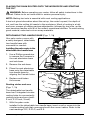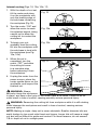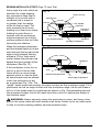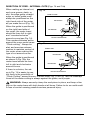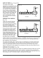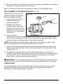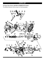
1
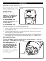
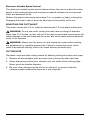
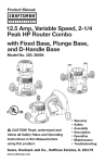
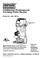
Operator’s Manual
Craftsman Professional
6.5 Amp Palm Router
Model No. 320. 28212
CAUTION! Read, understand and
follow all Safety Rules and Operating
Instructions in this Manual before
using this product.
•
•
•
•
•
•
Warranty
Safety
Unpacking
Description
Operation
Maintenance
Sears, Roebuck and Co., Hoffman Estates, IL 60179
www.craftsman.com
TABLE OF CONTENTS
Warranty
Page 2
Safety Symbols
Page 3
Safety Instructions
Pages 4-10
Unpacking
Pages 11-12
Description
Pages 13-15
Assembly
Page 15
Operation
Pages 16-29
Maintenance
Pages 29-30
Parts list
Pages 31-34
Sears Repair Parts Phone and Numbers
Back Cover
ONE YEAR FULL WARRANTY ON CRAFTSMAN PROFESSIONAL TOOL
If this Craftsman Professional tool fails to give complete satisfaction within
one year from the date of purchase, return it to any Sears store or parts &
repair center or other craftsman outlet in the United States for free repair
(or replacement, if repair proves impossible).
This warranty does not include expendable parts such as lamps,
batteries, bits, or blades.
This warranty applies for only 90 days from the date of purchase if this
product is ever used for commercial or rental purposes
This warranty gives you specific legal rights, and you may also have other
rights which vary from state to state.
Sears, Roebuck and Co., Hoffman Estates IL 60179
WARNING: Some dust created by using power tools contains chemicals
known to the state of California to cause cancer and birth defects or other reproductive harm.
SAVE THESE INSTRUCTIONS!
READ ALL INSTRUCTIONS!
28212 Manual_Revised_07-0713
Page 2
SAFETY SYMBOLS
The purpose of safety symbols is to attract your attention to possible dangers.
The safety symbols and the explanations with them deserve your careful
attention and understanding. The symbol warnings do not, by themselves,
eliminate any danger. The instructions and warnings they give are no substitutes
for proper accident prevention measures.
WARNING: Be sure to read and understand all safety instructions in this
manual, including all safety alert symbols such as “DANGER,” “WARNING,” and
“CAUTION” before using this router. Failure to follow all instructions listed below
may result in electric shock, fire, and/or serious personal injury.
SYMBOL MEANINGS
SAFETY ALERT SYMBOL: Indicates DANGER, WARNING, or CAUTION.
May be used in conjunction with other symbols or pictographs.
DANGER: Failure to obey this safety warning WILL result in death or serious
injury to you or to others. Always follow the safety precautions to reduce the risk
of fire, electric shock, and personal injury.
WARNING: Failure to obey this safety warning CAN result in death or serious
injury to you or to others. Always follow the safety precautions to reduce the risk
of fire, electric shock, and personal injury.
CAUTION: Failure to obey this safety warning MAY result in personal injury
to you or others or property damage. Always follow the safety precautions to
reduce the risk of fire, electric shock, and personal injury.
DAMAGE PREVENTION AND INFORMATION MESSAGES
These inform the user of important information and/or instructions that could
lead to equipment or other property damage if not followed. Each message is
preceded by the word “NOTE:” as in the example below:
NOTE: Equipment and/or property damage may result if these instructions are
not followed.
WARNING: The operation of any router can result
in foreign objects being thrown into your eyes, which can
result in severe eye damage. Before beginning power tool
operation, ALWAYS wear safety goggles or safety glasses
with side shield and a full-face shield when needed.
We recommend a Wide Vision Safety Mask for use over
eyeglasses or standard safety glasses with side shield,
available at Sears Stores or other Craftsman Outlets.
28212 Manual_Revised_07-0713
Page 3
SAFETY INSTRUCTIONS
WARNING: Be sure to read and understand all instructions in this manual
before using this router. Failure to follow all instructions may result electric shock,
fire, and/or serious personal injury.
WORK AREA SAFETY
•
Keep your work area clean and well lit. Cluttered workbenches and dark
areas invite accidents.
•
Do not operate power tools in explosive environments, such as in the
presence of flammable liquids, gases, or dust. Power tools create sparks
which may ignite the dust or fumes.
•
Keep bystanders, children, and visitors away while operating a power tool.
Distractions can cause you to lose control.
•
Make your workshop childproof with padlocks and master switches. Lock
tools away when they are not in use.
•
Make sure that the work area has ample lighting so you can see the
work and that there are no obstructions that will interfere with safe operation
before using your router.
PERSONAL SAFETY
•
Know your power tool. Read this operator’s manual carefully. Learn the
router’s applications and limitations, as well as the specific, potential hazards
related to this tool.
•
Stay alert, watch what you are doing, and use common sense when
operating a power tool.
•
Do not use the tool while tired or under the influence of drugs, alcohol, or
medication. A moment of inattention while operating power tools may result
in serious personal injury.
•
Dress properly. Do not wear loose clothing or jewelry. Pull back long hair.
Keep your hair, clothing, and gloves away from moving parts. Loose clothing
or long hair can be caught in moving parts. Air vents often cover moving
parts and should also be avoided.
•
Avoid accidental starting. Be sure switch is in the “OFF” position before
plugging the tool into an electric socket. Do not carry tools with your finger
on the switch. Carrying tools with your finger on the switch or plugging in
tools that have the switch in the “ON” position invites accidents.
•
Remove adjusting keys or blade wrenches before turning the tool “ON.”
A wrench that is left attached to a rotating part of the tool may result in
personal injury.
28212 Manual_Revised_07-0713
Page 4
•
D
o not overreach. Keep proper footing and balance at all times. Proper
footing and balance enable better control of the tool in unexpected situations.
•
A
lways secure your work. Use clamps or a vise to hold the workpiece
securely. It is safer than using your hand, and it frees both hands to operate
the tool.
•
U
se safety equipment. Always wear eye protection. A dust mask, non-skid safety
shoes, hardhat, and hearing protection must be used for appropriate conditions.
•
D
o not use on a ladder or unstable support. Stable footing on a solid
surface enables better control of the tool in unexpected situations.
POWER TOOL USE AND CARE
WARNING: Be sure to read and understand all instructions before operating
this router. Failure to follow all instructions listed below may result in electric
shock, fire, and/or serious personal injury.
•
A
lways use clamps or other practical ways to support and secure the
workpiece to a stable platform. Holding the work by hand or against your
body is unstable and may lead to loss of control.
•
D
o not force the tool. Use the correct tool and bit for your application.
The correct tool and bit will do the job better and safer at the rate for which
it is designed.
•
D
o not use the tool if switch does not turn it “ON” or “Off.” Any tool that
cannot be controlled with the switch is dangerous and must be repaired.
•
D
isconnect the plug from the power source before making any
adjustments, changing accessories, or storing the tool. Such preventive
safety measures reduce the risk of starting the tool accidentally.
•
N
ever leave the tool running. Always turn it off. Do not leave the tool until it
comes to a complete stop.
•
S
tore idle tools out of the reach of children and other untrained persons.
Tools are dangerous in the hands of untrained users.
•
M
aintain tools with care. Keep cutting tools sharp and clean. Properly
maintained tools with sharp cutting edges are less likely to bind and are
easier to control.
•
C
heck for misalignment or binding of moving parts, breakage of parts, and
any other condition that may affect the tool’s operation. If damaged, have
the tool serviced before using it. Many accidents are caused by poorly
maintained tools.
•
U
se only recommended accessories for this tool. Accessories that may be
suitable for one tool may become hazardous when used with another tool.
28212 Manual_Revised_07-0713
Page 5
ELECTRICAL SAFETY
WARNING: Do not permit fingers to touch the terminals of the plug when
installing or removing the plug from the outlet.
•
D
ouble insulated tools are equipped with a polarized plug (one blade is
wider than the other). This plug will fit in a polarized outlet only one way. If
the plug does not fit fully in the outlet, reverse the plug. If it still does not fit,
contact a qualified electrician to install a polarized outlet. Do not change the
plug in any way.
•
eliminates the need for a three-wire grounded power
Double insulation
cord and grounded power-supply system. Applicable only to Class II (doubleinsulated) tools.
•
This router motor is double insulated.
WARNING: Double insulation does not take the place of normal safety
precautions when operating this tool.
•
B
efore plugging in the tool, be sure that the outlet voltage supplied is within
the voltage marked on the tool’s data plate. Do not use “AC only” rated tools
with a DC power supply.
•
A
void body contact with grounded surfaces, such as pipes, radiators,
ranges, and refrigerators. There is an increased risk of electric shock if your
body is grounded.
•
D
o not expose power tools to rain or wet conditions or use power tools
in wet or damp locations. Water entering a power tool will increase the risk of
electric shock.
•
Inspect tool cords for damage. Have damaged tool cords repaired at a
Craftsman Service Center. Be sure to remain aware of the cord’s location and
keep it well away from the moving router.
•
D
o not abuse the cord. Never use the cord to carry the tool or to pull
the plug from an outlet. Keep the cord away from heat, oil, sharp edges,
or moving parts. Replace damaged cords immediately. Damaged cords
increase the risk of electric shock.
•
W
hen operating a power tool outside, use an outdoor extension cord
marked “W-A” or “W.” These cords are rated for outdoor use and reduce the
risk of electric shock.
EXTENSION CORDS
•
U
se a proper extension cord. Only use cords listed by Underwriters
Laboratories (UL). Other extension cords can cause a drop in line voltage,
resulting in a loss of power and overheating of the tool. For this tool, an AWG
(American Wire Gauge) size of at least 14-gauge is recommended for an
extension cord of 25-ft. or less in length. Use 12-gauge for a 50-ft.-long cord.
28212 Manual_Revised_07-0713
Page 6
•
E
xtension cords 100-ft. or longer are not recommended.
•
A
smaller wire gauge size has greater capacity than a larger number
(14-gauge wire has more capacity than 16-gauge wire; 12-gauge wire has
more capacity than 14-gauge). When in doubt use the smaller number. When
operating a power tool outdoors, use an outdoor extension cord marked
“W-A” or “W”. These cords are rated for outdoor use and reduce the risk of
electric shock.
CAUTION: Keep the extension cord clear of the working area. Position the
cord so that it will not get caught on lumber, tools, or other obstructions while
you are working with a power tool.
WARNING: Check extension cords before each use. If damaged, replace
them immediately. Never use a tool with a damaged cord, since touching the
damaged area could cause electrical shock, resulting in serious injury.
SAFETY SYMBOLS FOR YOUR TOOL
The label on your tool may include the following symbols.
V ......................................................Volts
A.......................................................Amps
Hz.....................................................Hertz
W......................................................Watts
min...................................................Minutes
...............................................Alternating current
..............................................Direct current
….............................................No-load speed
…...............................................Class II construction, Double Insulated
.../min...............................................Revolutions or Strokes per minute
.............................................. Indicates danger, warning or caution. It means
attention! Your safety is involved.
SERVICE SAFETY
•
If any part of this router is missing or should break, bend, or fail in any
way; or should any electrical component fail to perform properly: shut off the
power switch and remove the router plug from the power source and have the
missing, damaged, or failed parts replaced before resuming operation.
•
T
ool service must be performed only at a Craftsman Parts and Repair
Center. Service or maintenance performed by unqualified personnel could
result in a risk of injury.
28212 Manual_Revised_07-0713
Page 7
•
U
se only identical replacement parts when servicing a tool. Follow the
instructions in the maintenance section of this manual. Use of unauthorized
parts or failure to follow maintenance instructions may create a risk of electric
shock or injury.
SAFETY RULES FOR ROUTER
CAUTION: Cutting bits coast after the router is switched off.
•
H
old the tool by the insulated gripping surfaces (handles) when
performing an operation where the cutting tool may contact hidden wiring or
its own cord. Contact with a “live” wire will make the exposed metal parts of
the tool “live” and shock the operator.
•
M
aintain a firm grip on the router with both hands to resist starting torque.
•
N
ever attempt to use the router motor without first installing it in an approved
base. Failure to heed this warning could result in personal injury and damage
to the motor.
•
M
ake sure that the motor housing does not move up or down when clamped
in the base. If the motor is not securely clamped in a base, adjustments will
not be accurate.
•
T
ighten the collet/nut securely to prevent the cutting bit from slipping. If
the collet/nut is not securely tightened, the cutting bit may detach during use,
causing serious personal injury.
•
N
ever tighten the collet/nut without a cutting bit installed in the collet/nut.
•
U
se clamps or other practical ways to support the workpiece and secure it
to a stable platform, and to hold the workpiece rigidly in position. Holding
the workpiece by hand or against your body is unstable and may lead to
loss of control.
•
N
ever hold the piece being cut in your hands or across your legs. It is
important to support and clamp the workpiece properly in order to minimize
body exposure, bit binding, and loss of control.
•
C
lear the router-cutting-bit path of any obstructions before starting the motor.
Keep the cutting area clear of all foreign objects while motor is running.
•
M
ake sure that the cord will not “hang up” on the work piece or any other
object during routing operations.
•
M
ake sure that the cutting bit is not in contact with the workpiece before the
switch is turned on. The bit must always be running at the full selected speed
before coming into contact with the workpiece.
•
K
eep hands clear of the cutting bit when the motor is running to prevent
personal injury.
•
P
rovide clearance under the workpiece for the router cutting bit when
through-cutting.
28212 Manual_Revised_07-0713
Page 8
•
K
eep cutting pressure constant. Do not overload the motor.
•
U
se only sharp cutting bits that are not chipped or cracked. Blunt cutting
bits will cause stalling and burn the workpiece.
•
N
ever use this router motor with a cutting bit larger than 1-1/2 inch in
diameter.
•
A
lways use cutting bits that are designed for this router. Never use cutting
bits that are larger in diameter than the opening in the router sub-base.
Cutting bits that have cutting diameters larger than the opening could cause
possible loss of control or create other hazardous conditions that could
cause serious personal injury.
•
D
o not use large router cutting bits for freehand routing. Using large cutting
bits for freehand routing could cause loss of control or create hazardous
conditions that could result in serious personal injury. If using a router table,
large bits should be used for edging only.
•
D
o not remove more than 1/8-inch of material in a single pass. Excessive
depth of cut can result in loss of control that could result in personal injury.
•
T
urn the motor OFF after completing a cut, and let the motor come to a
complete stop before removing the router from the workpiece.
•
A
llow the motor come to a complete stop before putting the router down.
Cutting bits coast after the power is turned off.
•
D
isconnect the tool from the power source before making any adjustments
or changing cutting bits.
•
D
o not touch the collet/nut or cutting bit with your hands or fingers if you
are changing a bit immediately after use. The heat buildup from cutting could
cause severe burns. Always use the wrench provided.
•
A
void “climb cutting”. See “OPERATION” (pages 16-29) section in this
manual. “Climb-cutting” increases the chance for loss of control resulting in
possible serious injury.
WARNING: Use of this product can generate dust containing chemicals
known to the state of California to cause cancer, birth defects or other
reproductive harm. Some examples of these chemicals are:
•
Lead from lead-based paints.
•
Crystalline silica from bricks and cement and other masonry products.
•
Arsenic and chromium, from chemically treated lumber.
Your risk from these exposures varies, depending upon how often you do this
type of work. To reduce your exposure to these chemicals:
•
Work in a well-ventilated area.
•
Work with approved safety equipment, such as those dust masks that are
specially designed to filter out microscopic particles.
28212 Manual_Revised_07-0713
Page 9
Avoid prolonged contact with dust from power sanding, sawing, grinding, drilling
and other construction activities. Wear protective clothing and wash exposed
areas with soap and water. Allowing dust to get into your mouth or eyes or lie on
the skin may promote absorption of harmful chemicals.
WARNING: Use of this tool can generate and/or disburse dust, which may
cause serious and permanent respiratory or other injury. Always use NIOSH/
OSHA approved respiratory protection appropriate for the dust exposure. Direct
dust particles away from the face and body.
ADDITIONAL RULES FOR SAFE OPERATION
WARNING: Be sure to read and understand all instructions. Failure to follow
all instructions listed below may result in electric shock, fire, and/or serious
personal injury.
•
K
now your power tool. Read this operator’s manual carefully. Learn the
applications and limitations, as well as the specific, potential hazards related
to this tool. Following this rule will reduce the risk of electric shock, fire, and
serious injury.
•
A
lways wear safety glasses or eye shields when using this router.
Everyday eyeglasses may have impact-resistant lenses, but they are NOT
safety glasses.
•
P
rotect your lungs. Wear a facemask or dust mask if the operation is dusty.
•
P
rotect your hearing. Wear appropriate personal hearing protection during
use. Under some conditions, noise from this product may contribute to
hearing loss.
•
A
ll visitors and bystanders must wear the same safety equipment that the
operator of the router should wear.
•
Inspect the tool cord periodically and, if it is damaged, have it repaired at
your nearest Craftsman Service Center. Be aware of the cord location.
•
A
lways check the tool for damaged parts. Before further use of the tool,
a guard or other part that is damaged should be carefully checked to
determine whether it will operate properly and perform its intended function.
Check for misalignment or binding of moving parts, breakage of parts, and
any other condition that may affect the tool’s operation. A guard or other
part that is damaged should be properly repaired or replaced at a Craftsman
Service Center.
•
Inspect lumber and remove all nails before routing.
•
S
ave these instructions. Refer to them frequently, and use them to instruct
others who may use this tool. If someone borrows this tool, make sure they
have these instructions also.
28212 Manual_Revised_07-0713
Page 10
unpacking
WARNING: Your router should never be connected to a power source when
you are assembling parts, making adjustments, installing or removing collets/
nuts or cutting bits, cleaning, or when it is not in use. Disconnecting the router
will prevent accidental starting, which could cause serious personal injury.
1. C
arefully lift the router, with the 1/4-in. collet/ nut already installed, out of
the storage/carrying case and place it on a stable flat surface.
2. Locate the following:
• Edge Guide
• Collet/nut wrench
• Detachable two-handle base
3. Inspect the items carefully to make sure that no breakage or damage has
occurred during shipping. If any of the items mentioned is missing, (refer to
“PARTS LIST” illustration on page 10), return the router to your nearest Sears
store or Craftsman outlet to have the router replaced.
WARNING: If any parts are broken or missing, do not attempt to plug in the
power cord or operate the router until the broken or missing parts are replaced.
Failure to do so could result in possibly serious injury.
28212 Manual_Revised_07-0713
Page 11
PARTS LIST (Fig. 1)
Fig. 1
1. Palm Router with 1/4-in. Collet/nut
2. Detachable two-handle base
3. Collet/nut wrench
4. Edge Guide
28212 Manual_Revised_07-0713
Page 12
DESCRIPTION
KNOW YOUR ROUTER COMBO (Fig. 2)
Fig. 2
Router Motor Top Cap
Variable Speed Dial
Power cord
Dust-proof Shied &
On/Off Switch
Soft Grip
Micro Adjustment Knob
Cast-in Depth Scale
Motor Clamp
Base
Spindle Lock
Edge Guide Locking Knob
Sub-base
1/4-in. Collet/Nut
“Live-Tool Indicator”
Light
Handle
Circular-routing Holes
Cast-in Scale
Screw Hole
Sub-base
Detachable Handle Base
28212 Manual_Revised_07-0713
Page 13
PRODUCT SPECIFICATIONS
Rating
No load Speed
6.5 Amps
15000-28000RPM
Peak HP
Input
1.25
120-volts, 60Hz AC
Collets/Nuts and Cutting Bit Shank Diameters
1/4 in.
Base Diameter
Sub Base Opening (Diameter for cutting bit use)
Depth of Cut
3-5/8 in.
1-1/2 inches
1 inch (25.4mm)
NOTE: Before attempting to use your router, familiarize yourself with all of the
operating features and safety requirements.
Your palm router has a precision-built electric motor, which should only be
connected to a 120-volt, 60-Hz AC ONLY power supply (normal household
current). Do not operate on direct current (DC). This large voltage drop will cause
a loss of power and the motor will overheat. If the router does not operate when
plugged into a correct 120-volt, 60-Hz AC ONLY outlet, check the power supply.
This router has a10-ft., 2-wire power cord (no adapter needed).
This Palm Router has the following features:
1. 6
.5 Amp, 1-1/4 peak HP, variable-speed motor runs at 15,000 to 28,000
RPM (no-load speed).
2. V
ariable Speed Dial for matching the motor speed to the workpiece material
and bit size.
3. M
icro-adjust knob with scale cast in the motor housing for easily adjusting
the cutting height.
4. C
ompact motor housing constructed of Cast Aluminum / High Density
Nylon /Overmold for strength and user comfort.
5. 2
LED worklights provide high visibility of the bit and workpiece.
6. D
epth scale for accurate set-up
7. S
pindle lock for easy, one-wrench bit changes.
8. 1/4-in. self-releasing collet/nut.
9. D
etachable, two-handle base features ergonomically designed handles
with overmold for comfort and maximum control with reduced vibration.
10. 3 integrated circular routing holes in the detachable base for conveniently
routing circles and arcs (radii: 2-inch, 2-1/2-inch, 3-inch).
11. Ball bearings throughout the motor for smooth, efficient operation and long life.
28212 Manual_Revised_07-0713
Page 14
12. Large base opening and large chip shield constructed of cast aluminum
for lightweight durability and stability,
13. Durable, non-marring sub-base glides smoothly over the workpiece.
14. Impact-resistant motor-housing top cap helps protect the tool from damage.
15. Heavy-duty edge guide for accurate, parallel routs.
16. On/Off Rocker Switch with dust-proof cover is side mounted for added
visibility, easy access.
17. “Live-Tool Indicator” light shines green when the palm router is plugged
into a power source. The light is located on motor housing top cap next to
power cord inlet.
18. Replaceable brushes (replacements sold separately) for dependable service.
19. Impact-resistant case for easy carrying and storage.
ASSEMBLY
NOTE: This tool is shipped completely assembled. To install or remove bits or
add accessories, see the following instructions.
28212 Manual_Revised_07-0713
Page 15
operation
ROCKER “ON/OFF” SWITCH (Fig. 3)
Your palm router motor is turned
“ON” and “OFF” with the rocker
switch located on the top cap of
the motor housing.
Fig. 3
The left side of the rocker
switch (as you face it) is
marked “I” for “ON” and the
right side (as you face it) is
marked “O” for “Off.”
To turn the motor “ON”
Push the rocker switch to the
left side marked “I”
To turn the motor “OFF”
Push the rocker switch to the right side marked “O”
1. A
lways hold the router and cutting bit away from the workpiece when turning
the toggle switch “ON.”
2. C
ontact the workpiece with the router and cutting bit only after the router
has fully reached the selected speed.
3. R
emove the router and cutting bit from the workpiece only after turning the
router motor “OFF” and after the cutting bit has come to a complete stop.
SOFT START FEATURE
The soft-start feature minimizes torque twist by limiting the speed at which the
motor starts. This increases the motor’s life.
LED WORKLIGHTS (Fig. 4)
Fig. 4
Your palm router motor has
2 built-in worklights located
around the collet/nut to
provide high visibility of the
workpiece when cutting.
These lights are always “ON”
when the rocker switch is in
the “ON” position.
LED worklight
28212 Manual_Revised_07-0713
Page 16
Electronic Variable Speed Control
The electronic variable speed control feature allows the user to match the motor
speed to the cutting bit size and workpiece-material hardness for an improved
finish and extended bit life.
Reduce the speed when using extra large (1-in. or greater) or heavy cutting bits.
Changing the router’s rate of feed can also improve the quality of the cut.
SELECTING THE CUTTING BIT
This router comes with 1/4-in. collet/nut that accepts 1/4-inch-shank cutting bits.
WARNING: Do not use router cutting bits that have a cutting bit diameter
larger than 1-1/2 inches, as they will not fit through the sub-base opening and will
cause damage to the sub-base and the motor and could cause serious personal
injury to the operator.
WARNING: Always turn the motor off and unplug the router before making
any adjustments or installing accessories. Failure to unplug the router could
result in accidental starting, which can cause serious personal injury.
CUTTING BITS
Get faster, more accurate cutting results by keeping cutting bits clean and sharp.
1. Remove all accumulated pitch and gum from cutting bits after each use.
2. W
hen sharpening cutting bits, sharpen only the inside of the cutting edge.
Never grind the outside diameter.
3. B
e sure, when sharpening the end of a cutting bit, to grind so that the
clearance angle remains the same as it was originally.
28212 Manual_Revised_07-0713
Page 17
INSTALLING AND REMOVING THE CUTTING BIT (Fig. 5)
INSTALLING THE CUTTING BIT
1. T
urn the motor off and
unplug the router from the
power source.
Fig. 5
2. R
emove the motor
housing from the base.
NOTE: See instructions for
removing and installing the
motor housing from the fixed
base on page 20.
3. P
lace the motor, upside
down, on its top cap with
the collet/nut pointing up.
4. P
ress the spindle-lock
button to engage and lock the spindle shaft and the collet/nut (Fig. 5).
5. P
lace the wrench on the collet/nut and turn it counter-clockwise to slightly
loosen the collet/nut.
6. Insert the cutting-bit shank into the collet/nut assembly as far as it will go,
then back the shank out until the cutting edges are approximately 1/8 to 1/4inch away from the face of the collet/nut.
7. W
ith the cutting bit inserted and the spindle-lock button pressed in to
engage the shaft, place the wrench on the colle/nut and turn it clockwise
until the router cutting bit and the collet/nut are firmly tightened.
WARNING: Tighten the collet/nut securely to prevent the cutting bit from
slipping. If the collet/nut is not securely tightened, the cutting bit may detach
during use, causing serious personal injury.
NOTE: To ensure proper gripping of the cutting-bit shank and to minimize run-out,
the shank of the cutting bit must be inserted into the collet/nut at least 5/8-inch.
CAUTION: To prevent damage to tool, do not tighten collet/nut without a
cutting bit installed.
REMOVING THE CUTTING BIT (Fig. 5)
1. Turn the motor off and unplug the tool from the power source.
2. Remove the motor from the fixed base.
3. Place the motor, upside down, on its top cap with the collet/nut pointing up.
4. P
ress the spindle-lock button to engage and lock the spindle shaft and the
collet/nut (Fig. 5).
28212 Manual_Revised_07-0713
Page 18
5. P
lace the wrench on the collet/nut and turn it counterclockwise to slightly loosen
the collet/nut, and then remove the cutting-bit shank from the collet/nut.
NOTE: The collet/nut is self-releasing; it is not necessary to strike the collet/nut
to free the cutting bit. If the cutting bit seems to be stuck, loosen the collet/nut a
little more until it releases the cutting bit.
COLLET/NUT CARE
1. F
rom time to time, inspect the collet/nut to make sure that it is clean and that
it is gripping the cutting bit properly.
2. W
ith the cutting bit removed and with the spindle lock engaged, turn the
collet/nut counterclockwise until it is free from the motor’s spindle shaft.
3. B
low the collet/nut out with compressed air, and clean the tapered inside of
the collet/nut with a tissue or a fine brush.
4. A
lways make sure that the cutting bit shank, collet/nut, and motor spindle are
clean and free of woodchips, dust, residue, grease, and rust before re-installing.
5. A
pply a small amount of machine oil to the spindle shaft if it looks dry.
Always replace a worn or damaged collet/nut before further use.
ADJUSTING DEPTH OF CUT
WARNING: Your palm router should never be turned on or be connected
to the power source when you are assembling parts, making adjustments,
installing or removing the collet/nut or cutting bits, cleaning, or when it is not in
use. Disconnecting the router will prevent accidental starting, which could cause
serious personal injury.
NOTE: All depth adjustments must be made with the motor clamp open.
NOTE: For this palm router, the cutting-bit depth equals the amount of the
cutting bit that is exposed below the surface of the sub-base.
28212 Manual_Revised_07-0713
Page 19
To Adjust Depth (Fig. 6)
1. T
urn the motor off and
unplug the tool from the
power source.
Fig. 6
A
B
2. Install the router bit. The
collet/nut can accept only
bits with ¼-inch shanks.
3. W
ith one hand holding
the motor housing, open
Motor Clamp (A).
4. R
otate the Micro Adjust
Knob (B) to raise or lower
the motor to achieve the
desired cutting depth. The direction of the rotation is marked on the Micro
Adjust Knob (B).
5. Always use a ruler to confirm the cutting depth.
6. Once the depth of cut is set, close the motor clamp (A) securely.
NOTE: Making a single deep cut is never advisable. Too much side thrust and
torque can easily break small-diameter cutting bits. Larger cutting bits can result
in a rough cut and be difficult to guide and control. For these reasons, do not
exceed 1/8-in. depth of cut in a single pass.
The proper cutting depth for each pass is determined based on the workpiece
material, the cutting bit size and type, and the speed of the motor.
NOTE: Making test cuts is essential with most routing applications.
Always make several, progressively deeper cuts by starting at one depth and
then making several passes, each time increasing the cutting depth, until the
desired depth is reached.
Making a cut that is too deep will stress the motor and the cutting bit, and it may
burn the workpiece and dull the cutting bit. It could also “grab” too much of the
workpiece and cause you to lose control of the router, causing a serious accident.
To be certain that your depth settings are appropriate, always make test cuts in
scrap material similar to your workpiece before beginning your final cutting.
Remember, knowing the right depth for each cut comes with routing experience.
28212 Manual_Revised_07-0713
Page 20
PLACING THE PALM ROUTER ONTO THE WORKPIECE AND STARTING
THE CUT
WARNING: Before operating your router, follow all safety instructions in this
manual. Failure to do so could result in serious personal injury.
NOTE: Making test cuts is essential with most routing applications.
A test cut gives information about the set-up, the router’s speed, the depth of
cut, and how the cutting bit reacts to the workpiece. Much of routing is a trialand-error process of making various adjustments, followed by test cuts, as the
user becomes familiar with all of the router’s operational abilities. To avoid ruining
good material, make test cuts on scrap materials.
DETACHABLE TWO-HANDLE BASE (Figs. 7, 7a)
Your palm router comes with
a newly designed, detachable,
two-handle base with
overmold for comfort.
Fig. 7
Installing the palm router in the
detachable two-handle base
1. Use a Phillips screwdriver
to remove the 3 screws in
the cast aluminium base
and sub-base.
2. Remove the sub-base.
3. Place the cast aluminium
base onto the detachable
two-handle base by
aligning the 3 screw holes.
Fig. 7a
4. Replace and fasten
the screws.
Routing circles and arcs
(Figs. 7, 7a)
The detachable two-handle
base has 3 integrated circularrouting holes for conveniently
routing circles and arcs (radii:
2 inch, 2-1/2 inch, 3 inch).
Nail or Screw
1. W
ith the palm router
installed in the detachable two-handle base, insert a nail or screw into the
circular-routing hole that corresponds with the correct radius. Refer to the
cast markings: R 2, R 2-1/2, and R 3.
28212 Manual_Revised_07-0713
Page 21
2. T
ap the nail or drive the screw into the workpiece at the center point of the
planned arc or circle.
3. Proceed to rout according to the Operations instructions.
HEAVY-DUTY EDGE GUIDE (Figs. 8, 8a)
Your palm router comes with a
Heavy-Duty Edge Guide. This
edge guide can be used as
an aid in routing applications,
such as decorative edging,
straight-edge planing,
trimming, grooving, dadoing,
and slotting.
Fig. 8
To assemble:
1. L
oosen the knob on the
cast aluminum base to
accommodate the slotted
attachment arm on the
edge guide.
2. A
lign the slot in the
edge-guide attachment
arm with the shaft of the
knob, so that the edgeguide attachment arm is
between the flat washer
and the cast-aluminum
router base.
Fig. 8a
3. S
lide the edge-guide
attachment arm up until
it stops.
4. T
ighten the knob on the
cast-aluminum base to
secure the edge guide.
28212 Manual_Revised_07-0713
Page 22
EDGE ROUTING OR INTERNAL ROUTING
Edge routing (Fig. 9)
Fig. 9
1. W
ith the depth-of-cut
set, place the router base
plate on the edge of the
workpiece, making sure
that the cutting bit does
not contact the workpiece.
2. C
lamp an edge guide
(or board or metal
straightedge) in place, to
help guide the router’s
base when making an
edge cut.
3. T
urn the router “ON,” and
let the motor reach the selected speed.
4. To begin the cut, gradually feed the cutting bit into the edge of the workpiece.
5. Guide the router along the workpiece edge.
6. W
hen cut is completed, turn the motor “OFF,” and let cutting bit come to a
complete stop before removing it from the workpiece.
7. U
nplug the router from the power source, place the router upside down on
worktable, and inspect the finished cut.
WARNING: Always securely clamp the workpiece in place, and keep a firm
grip on the router base with both hands at all times. Failure to do so could result
in loss of control, causing possibly serious personal injury.
WARNING: Removing the cutting bit from the workpiece while it is still
rotating could damage the workpiece and result in loss of control, causing
serious personal injury.
NOTE: Making test cuts in scrap material that is similar to the workpiece is
essential. Learning how the router’s speed, depth-of-cut and cutting bit will react
in the workpiece will help produce quality cuts.
28212 Manual_Revised_07-0713
Page 23
Internal routing (Figs. 10, 10a, 10b, 11)
1. W
ith the depth-of-cut set,
tilt the router and place
it on the workpiece with
only the leading edge of
the sub-base contacting
the workpiece (Fig.10).
2. T
urn the motor “ON” and
allow the motor to reach
the selected speed, being
careful not to allow the
cutting bit to contact the
workpiece.
3. T
o begin your cut,
gradually feed the cutting
bit into the workpiece until
the sub-base is level with
the workpiece (see Fig.
10a, 10b).
4. W
hen the cut is
completed, turn the
motor “OFF” and allow
the cutting bit come
to a complete stop
before removing it from
the workpiece.
Fig. 10
Fig. 10a
Fig. 10b
Fig. 11
5. U
nplug the router from the
power source, place the
router upside down on the
worktable, and inspect the
finished cut.
WARNING: Always
securely clamp the workpiece
in place, and keep a firm grip on the router base at all times. Failure to do so
could result in loss of control, causing possibly serious personal injury.
WARNING: Removing the cutting bit from workpiece while it is still rotating
could damage the workpiece and result in loss of control, causing serious
personal injury.
NOTE: Making a single, deep cut is never advisable. Smaller diameter bits are
easily broken by too much side thrust and torque. Larger bits will cause a rough
cut and will be difficult to guide and control. For these reasons, do not exceed
1/8-in. depth of cut in a single pass.
28212 Manual_Revised_07-0713
Page 24
EDGING WITH A PILOT BIT (Figs. 12 and 12a)
Arbor-type bits with pilots are
excellent for edge shaping
any workpiece edge that is
straight or is curved with a
curvature that is equal to
or greater than the radius
of the bit that is used. The
pilot prevents the bit from
making a cut that is too deep;
holding the pilot firmly in
contact with the workpiece
edge throughout the cutting
process prevents the cut from
becoming too shallow.
When the workpiece thickness
and the desired depth of cut are
such that only the top part of the
edge is to be shaped, leaving
at least a 1/16-in. thick uncut
portion below, the pilot can ride
against the uncut portion of the
workpiece. (See Fig. 12.)
Fig. 12
Motor housing
Spindle Lock
Cutter-bit
Spindle
Collet/Nut
Fixed Base
sub-base
Pilot
TOP EDGE SHAPING
Workpiece
Top Edge of Workpiece
Fig. 12a
Workpiece
If the workpiece is too thin or
Pilot
the bit is set so low so that
there will be no uncut edge
Guide Board
WHOLE EDGE SHAPING
against which to ride the pilot,
Whole Edge of Workpiece
an extra board must be placed
under the workpiece to act
as a guide (see Fig. 12a). This
“guide” board must have exactly the same contour as the workpiece edge. If it is
positioned so that its edge is flush with the workpiece edge, the bit will make a
full cut. If the guide board is positioned as shown in Fig. 16a (extending beyond
the workpiece edge), the bit will make less than a full cut, altering the shape of
the finished edge.
WARNING: Always securely clamp the workpiece in place, and keep a firm
grip on the router base with both hands at all times. Failure to do so could result
in loss of control causing possibly serious personal injury.
28212 Manual_Revised_07-0713
Page 25
FEEDING THE ROUTER (Fig. 13)
The secrets to professional-looking routing are careful set-up for the cut, proper
depth-of cut-selection, knowing how the cutting bit reacts in the workpiece, and
the rate and direction of feed of the router.
DIRECTION OF FEED: EXTERNAL CUTS (Fig. 13)
Direction
1
Rout
End
Grains
First
Bit Rotation
3
Direction
Router Feed
Router Feed
Fig. 13
2
The router motor and cutting
bit rotate clockwise. This
requires the feed of the cutting
bit to be from left to right (see
Fig. 13). Feeding the bit from
left to right will cause the bit
to pull the router towards (up
against) the workpiece.
Router Feed
If the router is fed in the
Direction
opposite direction (right to
Cutting
left), the rotating force of
Bit
the cutting bit will tend to
Router Feed
4
throw the bit away from the
Direction
workpiece, making it hard to
control. This is called “Climb-Cutting:” cutting in the opposite direction of the
proper feed direction. “Climb Cutting” increases the chance of loosing control,
resulting in possible personal injury. When “Climb Cutting” is required (backing
around a corner, for example), exercise extreme caution to maintain control of
the router.
KICKBACK
Because of the high speed of the cutting bit during a proper feeding operation
(left to right), there is very little kickback under normal conditions. However, if
the cutting bit strikes a knot, an area of hard grain in the workpiece, or a foreign
object, the normal cutting action could be affected and cause “Kickback.”
This Kickback may cause damage to your workpiece, and could cause you to
lose control of the router, causing possible personal injury. Kickback is always
counterclockwise: the opposite direction of the clockwise cutting bit rotation.
To guard against and help prevent Kickback, plan the set-up and direction of
feed so that the router is always moving, and keep the sharp edges of the cutting
bit continuously biting straight into new (uncut) wood (workpiece). Also, always
inspect the workpiece for knots, hard grain, and foreign objects that could cause
a kickback problem.
28212 Manual_Revised_07-0713
Page 26
DIRECTION OF FEED - INTERNAL CUTS (Figs. 14 and 14a)
When making an internal cut,
such as a groove, dado, or
slot, the edge guide, straight
edge, or board guide must
always be positioned on the
right-hand side of the router
as you make the cut (Fig. 14).
When the guide is positioned
on the right hand side of
the router, the router travel
should be from left to right
and “counterclockwise”
around curves (see Fig. 14).
This counterclockwise action
around the curve could cause
“Climb cutting”. Always be
alert and exercise extreme
caution to maintain control of
the router when making this
type of cut around curves.
When the guide is positioned
as shown in Fig. 18a, the
router travel should be from
left to right and clockwise
around curves.
Fig. 14
Guide Outside
Bit Rotation
Thrust
Bit Rotation
Router Feed Direction
Guide
Fig. 14a
Guide Inside
Bit Rotation
Guide
Thrust
Bit Rotation
If there is a choice, the setRouter Feed Direction
up in Fig. 14 is easier to use,
but there is the possibility of
“Climb Cutting” around curves. In either case, Fig. 14 or Fig. 16a, the sideways
thrust of the router cutting is always against the guide, as is proper.
WARNING: Always securely clamp the workpiece in place, and keep a firm
grip on the router base with both hands at all times. Failure to do so could result
in loss of control causing possible serious personal injury.
28212 Manual_Revised_07-0713
Page 27
RATE OF FEED (Figs. 15 and 15a)
The proper rate of feed
depends on several factors: the
hardness and moisture content
of the workpiece, the depth of
cut, and the cutting diameter of
the bit. When cutting shallow
grooves in soft woods, such as
pine, you may use a faster rate
of feed. When making deep
cuts in hardwoods, such as
oak, you should use a slower
rate of feed.
Fig. 15
Bit
Shank
Cut
TOO FAST
Cutter
FEEDING TOO RAPIDLY
(Fig. 15)
Clean and smooth finished
cuts can only be achieved
when the cutting bit is rotating
at a relatively high speed,
taking very small bites, and
producing tiny, clean-cut chips.
Fig. 15a
Forcing the feed of the cutting
bit forward too rapidly slows
the RPM of the cutting bit, and
the bit takes larger bites as it
rotates. Larger bites mean larger
chips and a rough finish. This
forcing action can also cause
the router motor to overheat.
Bit
Shank
Cut
TOO SLOW
Cutter
Under extreme force-feeding conditions, the RPMs can become so slow and the
bites become so large that chips become partially cut off, causing splintering
and gouging of the workpiece.
The router will make clean, smooth cuts if it is allowed to run freely without the
overload of forced feeding. You can detect forced feeding by the sound of the
motor. Its usual high-pitched whine will sound lower and stronger as it loses
speed. Holding the router against the workpiece will also be more difficult to do.
FEEDING TOO SLOWLY (Fig. 15a)
When you feed the cutting bit too slowly, the rotating cutting bit does not cut into
new wood rapidly enough to take a bite. Instead, it scrapes away sawdust-like
particles. This scraping produces heat, which can glaze, burn, and mar the cut in
the workpiece and, in extreme cases, overheat the cutting bit.
28212 Manual_Revised_07-0713
Page 28
When the cutting bit is scraping instead of cutting, the router is more difficult to
control as you feed it.
With almost no load on the motor, the cutting bit has a tendency to bounce
off the sides of the cut in the workpiece, producing a cut with a rippled finish
instead of clean, straight sides.
MAINTENANCE
WARNING: To ensure safety and reliability, all repairs should be performed
by a qualified service technician at a Craftsman Service Center.
GENERAL
Only the parts shown on the parts list are intended for repair or replacement by
the customer. All other parts represent an important part of the double insulation
system and should be serviced only by a qualified Craftsman service technician.
WARNING: For your safety, always turn off the switch and unplug the router
motor from the power source before performing any maintenance or cleaning.
It has been found that electric tools are subject to accelerated wear and possible
premature failure when they are used to work on fiber glass boats and sports
cars, wallboard, spackling compounds, or plaster. The chips and grindings from
these materials are highly abrasive to electrical tool parts, such as bearings,
brushes, commutators, etc. Consequently, it is not recommended that this tool
be used for extended work on any fiberglass material, wallboard, spackling
compound, or plaster. During any use on these materials, it is extremely
important that the tool is cleaned frequently by blowing with an air jet.
WARNING: Always wear safety goggles or safety glasses with side shields
during power tool operations, or when blowing dust. If operation is dusty, also
wear a dust mask.
ROUTINE MAINTENANCE
WARNING: Do not at any time allow brake fluids, gasoline, petroleum-based
products, penetrating oils, etc. come in contact with plastic parts. Chemicals
can damage, weaken, or destroy plastic, which may result in serious personal
injury.
1. When work has been completed, clean the tool to allow smooth functioning
of the tool over time.
2. Use clean damp cloths to wipe the tool.
3. Check the state of all electrical cables.
4. Keep the motor air openings free from oil, grease, and sawdust or
woodchips, and store tool in a dry place.
28212 Manual_Revised_07-0713
Page 29
5. B
e certain that all moving parts are well lubricated, particularly after lengthy
exposure to damp and/or dirty conditions.
Refer to Collet/nut Care and Cutting Bits on page 19 for Collet/Nut care.
REPLACEMENT OF CARBON BRUSHES (Fig. 16)
Replacement brush sets are
available through Craftsman
Parts and Repair Centers.
1. U
nplug the router motor
before inspecting or
replacing brushes.
Fig. 16
Cap
Ears
Brushes
2. R
eplace both carbon
brushes when either has
less than 1/4-in. length of
carbon remaining, or if the
spring or wire is damaged
or burned.
3. U
sing a slotted
screwdriver, remove the black plastic cap on each side of the router motor
(Fig. 20) and carefully withdraw the spring-loaded brush assemblies. Keep
brushes clean and sliding freely in their guide channels.
NOTE: To reinstall the same brushes, make sure the brushes go back in the
same way they came out. This will avoid a break-in period.
4. Insert new brush assemblies into the guide channels with the carbon part
going in first, being certain to fit the two metal “ears” into their slots in the
channel (Fig. 16).
5. R
emember to replace both end caps after inspecting or servicing the
brushes. Tighten the caps snugly, but do not over-tighten. The router should
be allowed to “run in” (run at no load without a cutting bit) for 5 minutes
before use, to seat the new brushes properly.
WARNING: For your safety, always turn off the switch and unplug the router
motor from the power source before performing any maintenance or cleaning.
LUBRICATION
All of the bearings in this tool are lubricated with a sufficient amount of highgrade lubricant for the life of the tool under normal operating conditions.
Therefore, no further lubrication is required.
28212 Manual_Revised_07-0713
Page 30
parts list
6.5 Amp Palm Router MODEL NUMBER 320.28212
The Model Number will be found on the Nameplate.
28212 Manual_Revised_07-0713
Page 31
parts list
6.5 Amp Palm Router MODEL NUMBER 320.28212
The Model Number will be found on the Nameplate.
No.
Part No.
1
3703873000
Decorate Cover
1
2
3123373000
Transparent Cap
1
3
3123331000
Rear Cover
1
4
5610103000
Tapping Screw
3
5
3120234000
Cord Anchorage
1
6
4930004000
Connecter
1
7
3123374000
Power Indicator Cover
1
8
2822416000
Speed Adjustor ASSY
1
9
4810002000
Power Cord & Plug
1
10
3121011000
Cord Guard
1
11
4960249000
Carbon Brush
2
12
2800149000
Brush box
2
13
3123456000
Brush holder cover
2
14
4870051000
Switch
1
15
3704018000
Fixing Board
1
16
3123386000
Switch Cover
1
17
2822258000
LED Holder ASSY
1
18
3320480000
Motor Housing
1
19
5610042000
Tapping Screw
4
20
3123609000
Fan Baffle
1
21
2740249000
Stator
1
22
5610050000
Tapping Screw
2
23
3120997000
Bearing holder
1
24
5700006000
Ball Bearing
1
25
2750846000
Rotor
1
26
5660018000
Circlips For Shaft
1
27
5630216000
Collet Nut
1
28
3550760000
Collet
1
29
5620031000
Screw
2
30
3703875000
Lock Cover
1
28212 Manual_Revised_07-0713
Part Name
Quantity
Page 32
No.
Part No.
31
3123334000
Spindle Lock Button
1
32
3703876000
Spindle Lock
1
33
3660028000
Stop Spring
1
34
5660022000
Circlips For Hole
1
35
5700018000
Ball Bearing
1
36
3420568000
Bearing Support
1
37
5610034000
Tapping Screw
2
38
3420586000
Gear Rack
1
39
5620062000
Screw
2
40
5620103000
Slotted Shoulder Screw
1
41
5650206000
Spring Washer
1
42
3402197000
Knob
1
43
3420569000
Mounting
1
44
5650020000
Spring Washer
1
45
5650019000
Plain Washer
1
46
3402200000
Lock Bolt
1
47
5630006000
Prevailing Torque Haxagon Nut
1
48
5650013000
Plain Washer
1
49
3660094000
Spring
1
50
5650012000
Plain Washer
1
51
3703874000
Clamping Lever
1
52
3550209000
Spring Pin
1
53
3550880000
Mitre Lock Bolt
1
54
3123332000
Base Plate
1
55
5620067000
Screw
3
56
3402196000
Handle
2
57
3420579000
Bottom Support
1
58
5620021000
Hexagon Socket Screw
2
59
3123333000
Base Plate
1
60
5620071000
Screw
4
61
3700641000
Wrench
1
62
5630056000
Wing nut
1
63
5650020000
Spring Washer
1
28212 Manual_Revised_07-0713
Part Name
Quantity
Page 33
No.
Part No.
64
5650017000
Plain Washer
1
65
3703973000
Guide
1
66
5620195000
Bolt
1
67
3703972000
Guide
1
64
5650017000
Plain Washer
1
65
3703973000
Guide
1
66
5620195000
Bolt
1
67
3703972000
Guide
1
28212 Manual_Revised_07-0713
Part Name
Quantity
Page 34
Notes
28212 Manual_Revised_07-0713
Page 35
Get it fixed, at your home or ours!
Your Home
For repair – in your home – of all major brand appliances,
lawn and garden equipment, or heating and cooling systems,
no matter who made it, no matter who sold it!
For the replacement parts, accessories and
owner’s manuals that you need to do-it-yourself.
For Sears professional installation of home appliances
and items like garage door openers and water heaters.
1-800-4-MY-HOME®
Call anytime, day or night
(1-800-469-4663)
(U.S.A. and Canada)
www.sears.com
www.sears.ca
For expert home solutions advice: www.managemyhome.com
Our Home
For repair of carry-in products like vacuums, lawn equipment,
and electronics, call or go on-line for the nearest
Sears Parts & Repair Service Center
1-800-488-1222 (U.S.A.)
1-800-469-4663 (Canada)
Call anytime, day or night
www.sears.com
www.sears.ca
To purchase a protection agreement on a product serviced by Sears:
1-800-827-6655 (U.S.A.)
Para pedir servicio de reparación
a domicilio, y para ordenar piezas:
1-888-SU-HOGAR®
(1-888-784-6427)
1-800-361-6665 (Canada)
Au Canada pour service en français:
1-800-LE-FOYERMC
(1-800-533-6937)
www.sears.ca
© Sears Brands, LLC
® Registered Trademark / TM Trademark / SM Service Mark of Sears Brands, LLC
® Marca Registrada / TM Marca de Fábrica / SM Marca de Servicio de Sears Brands, LLC
MC
Marque de commerce / MD Marque déposée de Sears Brands, LLC