1
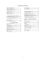
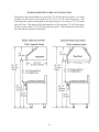
VIKING RANGE CORPORATION, P. O. DRAWER 956, GREENWOOD, MS.38930 USA
F90600A
11/20/03
TABLE OF CONTENTS
TABLE OF CONTENTS----------------------
Customer information-----------------------Model / Serial Number Logic--------------Warranty Statement--------------------------Proximity to Side Cabinets -----------------Anti-Tip Device------------------------------Range Leveling------------------------------Wood Overlay (Hood)------------------------
Gas Combustion------------------------------- 31
Gas Connections---------------------------- 32/33
L.P. Conversion----------------------------34
2
3
4
5
6/7
8
9
10
Electrical Connections---------------------- 35/36
Service Burner Spark Module---------------- 37
Pre-Heat PC Board----------------------------- 38
Component Contacts (VDSC367)------------ 39
Wiring Diagram (VDSC367)------------------ 40
Wiring Diagram Surface Burner Module---- 41
Wiring Diagram Dual Fuel 48”--------------- 42
Component Contacts Dual Fuel 48”---------- 43
COMPONENTS/COLOR CODED WIRES
Component Description--------------------- 11/16
P.C. Timer Board Voltage Readings--------- 17
8-Position Selector Switch-------------------- 18
BREAK OUT WIRING DIAGRAMS
Bake---------------------------------------------- 44
Convection Bake-------------------------------- 45
Convection Cook-------------------------------- 46
Broil----------------------------------------------- 47
Maxi-Broil---------------------------------------- 48
Convection Broil------------------------------- 49
Self-Clean-------------------------------------- 50
Self-Clean (Left Hand Oven—48”)--------- 51
Troubleshooting Guide-------------------- 52/54
VDSC “ Locked” Door----------------------- 55
Oven Calibration----------------------------- 19
Heating Elements Description---------------- 20
VDSC367 Disassemble
Rear Component Location--------------------- 21
Range Top---------------------------------------- 22
Griddle Assembly------------------------------ 23
Control Panel (Serial / Tech Sheets)--------- 24
Griddle Removal------------------------------- 25
Burner / Burner Support---------------------- 26
Griddle Gas Valve----------------------------- 27
Griddle Valve and Igniter Circuit------------ 28
Igniter System---------------------------------- 29
Door Lock Motor------------------------------ 30
Griddle Assembly------------------------------ 56
Grill Assembly---------------------------------- 57
2
IMPORTANT INFORMATION
GENERAL INFORMATION
1. WARNING: The use of cabinets for
storage above the appliance may result
in a potential burn hazard. Combustible
items may ignite, metallic items may
become hot and cause burns. If a
cabinet storage is to be provided the risk
can be reduced by installing
a
rangehood that projects horizontally a
minimum of 5” beyond the bottom of the
cabinets.
2. WARNING: This appliance shall not
be used for space heating.
This
information is based on safety
considerations.
3. When removing the oven for cleaning of
servicing;
A) Shut off gas at main supply
B) Disconnect AC power supply,
C) Disconnect gas line to the inlet pipe.
D) Carefully remove the range by
pulling outward. CAUTION: Range
is heavy; use care in handling
The information contained in this manual is
intended for use by a qualified service technician
who is familiar with the application of all safety
procedures required in the repair of any gas or
electric appliance, and who is equipped with the
proper tools and testing instruments.
Repairs covered in this manual and made by
unqualified persons can result in hazards
developing due to improper assembly or
adjustment.
Inexperienced persons making such repairs
subject themselves to the risk of injury or
electrical shock which can be serious or even
fatal.
IMPORTANT NOTE TO CUSTOMER
If you perform service on your own Viking
product, you must assume responsibility of
personal injury or property damage which may
result.
WARNING:
ELECTRICAL GROUNDING
INSTRUCTIONS
This appliance must be electrically grounded
in accordance with local codes or, in the
absence of codes, with the National
Electrical Code,
ANSI/NFPA 70 –
latest edition.
Viking will not be responsible for injury or
property damage arising from service performed
by other than Viking Factory Authorized Service
Agencies.
FOR PERSONAL SAFETY, THIS APPLIANCE
MUST BE PROPERLY GROUNDED.
Viking Preferred Service
P.O. Drawer 956
Greenwood, Ms. 38930
In order to locate a Viking Factory Authorized
Service Agency, please consult the dealer from
whom you purchased this product. You may
also write to:
3
4
56
PROXIMITY TO SIDE CABINET INSTALLATION
1.
2.
3.
4.
Range / Range tops may be installed directly adjacent to existing 36" high base cabinets.
IMPORTANT-the top grate support MUST be 3/8" above the adjacent base cabinet countertop.
This may be accomplished by raising the unit, ( using the adjustment spindles on the range legs)
or ( using shims for the range top).
The range / range top CANNOT be installed directly adjacent to sidewalls, tall cabinets, tall
appliances, or other side vertical surfaces above 36" high. There must be a minimum of 6" side clearance
from the range to such combustible surfaces above the 36" counter height.
Within the 6"side clearance to combustible vertical surfaces above 36", the maximum wall cabinet
depth must be 13" and wall cabinets within this 6"side clearance must be 18" above the 36" high
countertop.
Wall cabinets above the range / range top must be a minimum of 36" above the cooking surface for
the full width of the range / range top.
6
1.
2.
3.
4.
PROXIMITY TO SIDE CABINET INSTALLATION
(24” W. MODELS)
This range may be installed directly adjacent to existing 36” high base cabinets.
IMPORTANT: The top grate support MUST be 3/8” above the adjacent base cabinet
countertop. This may be accomplished by raising the unit using the adjustment
spindles on the legs.
The range CANNOT be installed directly adjacent to sidewalls, tall cabinets, tall
appliances. or other side vertical surfaces above 36” high. There must be a minimum
of 6” side clearance for the 4-burner and Griddle model ranges and a minimum of 9”
side clearance for the Char-Grill model to such combustible surfaces above the 36”
counter height.
Within the side clearance to combustible vertical surfaces above 36”, the maximum
wall cabinet depth must be 13” and wall cabinets within this side clearance must be
18” above the 36” high countertop.
Wall cabinets above the range must be a minimum of 42” above the range cooking
surface for the full width of the range.
7
STABILITY DEVICE INSTALLATION INSTRUCTIONS
1. The anti-tip bracket is to be attached to the rear wall as shown. The dimension for the
bracket location from the floor is to be determined after the range leg have been
adjusted to the proper installation height shown in the installation instructions and the
range has been leveled.
2. Measure from the floor to the bottom of the anti-tip opening located on the back of
the range
3. Locate the anti-tip bracket on the wall with the top left corner at the measured
dimension (A) plus ½” (1.3cm) from the floor and 5/8” (14.3cm) from where the left
side of the range (facing range) is to be located
4. Slide range into place. Be sure the anti-tip bracket slides into the anti-tip opening.
RANGES EQUIPPED WITH CASTERS
1. Adequate means must be provided
to limit the movement of the range
casters without depending on the
connector and /or quick disconnect
device. The “restraint” should be
inspected as
part
of the
maintenance and safety procedure.
Restraint cable must be connected
at all times when range is in use.
2. When using the quick disconnect
device and /or casters, the
“restrainer” must be attached to the
wall and to the rear of the range.
3. If disconnection of the restraint is
necessary, ensure the restraint is
reconnected after the range has been
returned to its original position.
8
RANGE LEVELING
Careful leveling of the range is critical not
only to performance, but also to allow the
alignment of oven doors and drip tray.
Closely follow the procedures below to
ensure proper performance and
appearance of the range. The range being
even slightly out of level will significantly
contribute to misalignment of oven doors.
•
1. If the floor is smooth and level, level
the unit with the screw thread of the legs.
Set the high corner of the range so that the
top of the grate support is 3/8" above the
countertop, and level the range to the high
corner.
front leveling leg will cause the top of
the door to move to the right.
Using the left front leveling leg will give
you the opposite effect. Raising the left
front corner will move the top of the
door to the right. Lowering the corner
will move the top of the door to the left.
The rear leveling legs will also have an
effect on the door alignment.
4. After the range is properly leveled , the
drip tray handle may be aligned by
loosening the screws and adjusting the
handle horizontally within the limits
provided by the slotted screw holes.
2. If the floor is uneven or has a decided
slope, level the unit with metal shims, as the
adjustment required may exceed the thread
available in the leg.
5. A carpenters’ spirit level should be
placed across the top of the range and the
unit leveled front-to back, side-to side and
vertically. If it is not level, burner
combustion may be erratic, liquid or semiliquid batters will cook at an angle, and the
unit may not function efficiently.
3. Proper and careful leveling of the range
is necessary for proper alignment of the
oven doors.
The body of the range does not have a
rigid frame to hold it into one position.
This non-rigid framework allows the
range to shift with un-level floors or
slanted cabinets.
Moving any one of the adjustable leveling legs
up or down will shift the range body. Use the
vertical line between the edge of the door and
the left side trim or center trim on the 2 door
models to adjust the leveling legs.
When adjusted properly
this space will
be uniform from the top to the bottom of
the door. The bottom corner of the end
panel will move in or out. Adjust this lower
corner to have an equal space from the top
to the bottom of the door.
• Increasing the length of the right front
leveling leg will raise the right front
corner of the range, moving the top of
the door to the left. Lowering the right
9
WOOD/COMPOSITE OVERLAY INSTALLATION
The bottom of the hood should be no less than 27” (68.6cm) above the grates. It is more
desirable for the bottom of the hood to be 29 5/8” to 35 5/8” above the grates. This
would typically result in the bottom of the hood being 66” (167.6cm) to 72” (187.9cm)
above the floor. The bottom of the hood should never be more than 72” (182.9cm) above
the floor or more than 35 5/8” (90.5cm) above the grates. These dimensions provide for
safe and efficient operation of the hood.
10
COMPONENTS
(WITH COLOR CODED WIRIES)
CONTROL CIRCUIT BOARD (P.C. BOARD)
DUAL FUEL SELF-CLEAN FREE-STANDING RANGES
WITH SEALED BURNERS
Function: The Door Lock Control / Timer is
activated by the line voltage at the “ SEL”
( 1 ) contact. Relay “ RL1" ( 2 ) and “RL2"
( 3 ) close providing voltage to the Door Lock
Motor. The Relays stay closed until 10
seconds after sensor #3 ( 4 ) receives a signal
that the Door Lock is fully closed. Once this
happens Relay “RL2" ( 3 ) opens to stop the
Door Lock Motor. Relay “RL1"
( 1 ) stays closed providing voltage to the Auto
Reset thermostat. Relays “RL3" and “RL4"
close powering the Cooling Fan Motor and
Cycle Relay. “RL3" and “RL4" will stay
closed for 3 ½ hours unless power is
interrupted to sensor #3 ( 4 ) or SEL ( 1 ). In
which case “RL3" and “RL4" will open,
interrupting the clean cycle and Cooling Fan,
and “RL2" ( 3 ) will close, opening the Door
Lock. “RL2" ( 3) will stay closed until 2
seconds after sensor # 4 ( 5 ) is powered.
AUTO RESET SWITCH: DUAL FUEL SELF-CLEAN
FREESTANDING RANGES WITH SEALED BURNERS
Function: The Auto Reset Switch is a single
pole / double throw switch ( thermostat )
which is activated by a thermo-bulb and lever
which is calibrated to 575* F plus / minus 25*
F. Clean door lock below 575* F. The Door
Lock Motor is energized through the Auto
Reset Switch ( thermostat ) contacts 2 - 1.
Clean door lock above 575* F. Auto Reset
Switch (thermostat ) switches to contacts 1 -3
turning on the Door Lock indicator Light and
disables the Door Lock Motor circuit. Final
below 575* F.
Auto Reset Switch (
thermostat ) switches to contacts 1 -2, turning
off the Door Lock Motor circuit through door
Lock Motor / Timer Relay LS2 - M1. Door
Lock Motor operates until 2 seconds after
sensor 4 is signaled by VC that the Door Lock
switch SW1 has been closed mechanically by
the door lock bolt. The Door Lock / Timer
switches LS2 - M1 and LS1-L1 open and the
timer resets.
11
HIGH LIMIT SWITCH: DUAL FUEL SELFCLEAN FREE-STANDING RANGES WITH SEALED
BURNERS
Function: The Switch has a ½ “ bi-metal
disc. The two metals have different thermal
coefficients of expansion which cause the
disc to bow as it heats up. When it reaches
the calibration temperature the disc snaps
open, which opens the electrical contacts.
The Switch opens when temperature reaches
275°F plus or minus 9°F and will close
when temperatures are 248° F plus or minus
9°F.
COOLING FAN LIMIT SWITCH:
DUAL
FUEL SELF-CLEAN FREE-STANDING RANGES
WITH SEALED BURNERS
Function: The Switch has a ½ “ bi-metal
disc. The two metals have different thermal
coefficients of expansion which cause the
disc to bow as it heats up. When it reaches
the calibration temperature the disc snaps
closed, which closes the electrical contacts.
The Switch closes when temperatures reach
230°F plus or minus 9°F and will open when
temperatures are below 203°F plus or minus
9°F.
SELECTOR SWITCH (8 POS)
SELECTOR SWITCH (8 POS)
(PJ030001)
Function: Rotating the shaft twists a cam
which moves one or more spring loaded
levers, which make contact with a terminal
closing the circuit.
SELECTOR SWITCH (PJ030009)
VDSC485(LH)
SELECTOR SWITCH ( 3 POS )
SELECTOR SWITCH (3 POS)
(PJ030010)
OVEN THERMOSTAT
Function: As the shaft is rotated from the
OFF position clockwise, an internal cam
pushes a lever, which increases the
temperature at which the thermostat cycles.
Rotating the shaft 212° (angle °) switches an
external (clean) Micro Switch to the closed
position.
12
COMPONENTS (continued)
DOOR LOCK MOTOR:DUAL
FUEL SELFCLEAN FREESTANDING RANGES WITH SEALED
BURNERS’
Function: When the Door Lock Motor is
powered it turned a cam which pulls back a
lever. As the lever moves back it allows a
micro switch (SW1) to open. When the
lever reaches the fully closed position it
closes a double stacked micro switch (SW2
& SW3). Door lock switch SW2 completes
the circuit to sensor #3 on the Door Lock
Control/timer board. After 10 seconds LS1M1 opens, stopping the Door Lock motion.
Door Lock Switch #3 closes T1-T2 and T3T4 energizing Power Relay #1 and the
Cooling Fan. Closing Power Relay contacts
supplies 240 VAC to both Broil Elements
and 120 VAC to the Bake Element.
POWER RELAY #1 (PM010129): DUAL
FUEL SELF-CLEAN FREESTANDING RANGES WITH
SEALED BURNERS
Function: Relay #1 (power) supplies power
to the Bake and Broil Elements.
RELAY #2 - #3 - #5 - #6
VEDO205 (PM010020)
13
COMPONENTS (continued)
RELAY #2 – #3 - #5 (PM010025): DUAL
FUEL SELF-CLEAN FREE- STANDING RANGES WITH
SEALED BURNERS.
Function: Setting the selector switch to clean
closes the Heating Element circuits 4-F, 1N, 2-L2, 3-L2 and Door Lock Module /
Timer circuit J-6, energizing Relay #2.The
thermostat cycling contacts 1 to 2 and the
clean switch contacts 3 to 4 close energizing
Relay #3. Relay #3 allows circuit J-6 to turn
on the Clean Indicator Light and enable the
Door Lock Module / Timer to close Relays
LS1-L1 and LS2 - M1. This powers the
Door Lock Motor until 10 seconds after
Sensor 3 is signaled by VC that Door Lock
Switch SW2 has been closed mechanically
(along with SW3) by the Door Lock Bolt.
RELAY #4 (PM010129)
VDSC485 (LH )
14
COMPONENTS (continued)
CONVECTION FAN MOTOR:DUAL FUEL
SELF-CLEAN FREE STANDING RANGES WITH
SEALED BURNERS
Function: Provides an even flow of air
in the oven cavity for more even
baking.
COOLING FAN MOTOR
Function: Provides a continuous supply
of cool air during self clean cycles to
keep the Door Lock Motor and
associated circuits cool.
OVEN LIGHT
Function: Provides interior oven light for
viewing baking products.
15
P.C. CONTROL BOARD WIRING
FOR RELAYS T4 – T3 – T2 – T1 – T6 – T5
16
VOLTAGE READINGS
MEASURED WITH DOOR OPEN
T4
107VAC
70VAC
T3
4VAC
16VAC
T2
4VAC
16VAC
T1
5VAC
1VAC
MEASURED WITH DOOR LOCKED
T4
80VAC
56VAC
T3
85VAC
56VAC
T2
90VAC
56VAC
T1
93VAC
56VAC
VC--4VDC
SENSOR 3--3VDC SW2 closed in self
clean (Locked).
SENSOR 4--4VDC SW1 closed with clean
lock open.
M1--120VAC lock motor supply voltage.
(31VAC in locked position)
LS2--70VAC (unlocked)--55VAC (locked)
L1-- 70VAC (unlocked)--56VAC (locked)
L2/M2--16VAC(unlocked)--32VAC
(locked)
LS1--107VAC (locked or unlocked)
SEL--120VAC SUPPLY
17
8 POSITION SELECTORSWITCH
(With shaft position and internal connections)
SELF CLEAN
Selector Switch closes Heating Element contacts
4-F, 1-N, 2-L2, 3-L2, and Door Lock Module /
Timer contacts J-6 energizing Relay #1.
Thermostat Clean Position closes Thermostat
cycling contacts 1-2 and normally open (N) common (C) energizing Relay #3.
Relay # 3 turns on the Clean indicator Light and
energizes Door Lock Module / Timer (PC
Board) relays LS1-L1 and LS2-M1, also
supplying 120VAC to SEL on the PC board
Relays LS1 and LS2 turns the Door Lock Motor
on through the Auto Reset Thermostat contacts
2-1.
Door Lock Motor rotates opening SW1 and
closing SW2 and SW3.
Door Lock Switch #2 completes the circuit to
sensor #3 on the PC board. After 10 seconds
LS1-M1 opens, stopping the Door Lock motion.
Door Lock Switch #3 closes T1-T2 and T3-T4
energizing Power Relay #1 and the Cooling Fan .
Closing Power Relay #1's contacts supplies
240VAC to both Broil Elements and 120VAC to
the Bake Element.
CLEAN DOOR LOCK ABOVE 575°F ± 25°F
Auto Reset Thermostat switches to contacts 1-3
turning on the Door Lock indicator Light and
disables the Door Lock Motor circuit.
CLEAN TEMPERATURE (875°F)
REACHED.
Door Lock Module / Timer opens T3 -T-4 and
T1-T2 turning off the Cooling Fan, now powered
by the Fan Limit Switch when needed, and opens
the circuit to the Power Relay #1 disabling the
Heating Elements.
FINAL BELOW 575°F ± 25°F
Auto Reset Thermostat switches to contacts 12. turning off the Door Lock Motor circuit
through Door Lock Motor / Timer Relay LS2-M1. Door Lock Motor operates until 2 seconds
after sensor 4 is signaled by VC that the Door
Lock /Timer switches LS2- M1 and LS1-L1
open and the Timer reset.
18
OVEN TEMPERATURE CALIBRATION
DUAL FUEL RANGES SELF-CLEAN FREESTANDING RANGES WITH SEALED BURNERS
Electric oven calibration using the EATON
thermostat. The adjustment screw is located
on the bottom of the thermostat ( 3/32 Allen
head screw ). Each 1/4 turn is equal to
approximately 35 degrees. COUNTER
CLOCKWISE adjustment will DECREASE the
temperature. CLOCKWISE adjustment will
INCREASE the temperature.
If the oven temperature is off more then 50 degrees
you should replace the thermostat.
REMEMBER WHEN YOU CHANGE THE
OVEN TEMPERATURE YOU ARE ALSO
CHANGING THE SELF-CLEAN
TEMPERATURE. (As a rule of thumb you should
only calibrate the thermostat to increase the oven
temperature.)
A. Center Oven Temperature Check: Before
turning the oven on, check the thermostat
sensor bulb position. It should be straight, no
kinks and secured in the mounting clips.
F. For convection test lower the oven temperature
to 325°F. Preheat the oven with convection fan
on.
TEMPERATURE; CONVECTION OVEN
B. Place the oven rack in the center of the oven.
CYCLE
C. Place a loaded thermocouple lead in the center of
the rack and close the door. Avoid touching
metal with the thermocouple junction.
I.
E. Cycle the oven 5 times; Average the 3rd, 4th,
and 5th cycles. The temperature is acceptable if
the average is 350°F ± 25 °.
TEMPERATURE: CONVENTIONAL OVEN
2
3
4
5
3
AVERAGE
HIGH
(XX)
(
)
(
)
(
)
LOW
(XX)
(
)
(
)
(
)
H. On convection baking place pans on rack
positions 2 and 4.
NOTE: Do not overshoot the 350F° mark. When
you go beyond 350°F, return the control to the
lowest setting and reset to 350°F.
1
2
G. On conventional baking place pans in the center
of the oven.
D. Set the selector switch to “ BAKE” and the
temperature dial to 350°F.
CYCLE
1
AVERAGE
HIGH
( XX) (XX)
(
) (
) (
)
(
)
LOW
(XX) (XX)
(
) (
) (
)
(
)
19
Uneven temperatures left to right in the oven:
1. Check air shutter adjustment: sharp blue
flame, no yellow tipping.
2. Check orifice hood adjustment.
VOLTAGE and RESISTANCE READINGS
BAKE ELEMENT:
“A” to “B”
21.1 Ohms
“A” to “B”
240VAC during Bake and
Convection Bake.
30” – 2750 Watts
36” – 3250 Watts
BROIL ELEMENT:
“A” to “D” ( outside element )
32.6 Ohms
1750 – Watts
“A” to “D”
50VAC during Bake and
Convection Bake.
240VAC during Maxi Broil.
240VAC during Convection Broil
240VAC during Self-clean
“B” to “C” ( inside element )
45.2 Ohms
1250 Watts
“B” to “C”
70VAC
during
Bake
and
Convection Bake.
240VAC during Mini Broil
240VAC during Maxi Broil
240VAC during Convection Broil
240VAC during Self-clean
CONVECTION ELEMENT:
“A” to “B”
26 Ohms
“A” to “B”
240VAC during Convection Cook
2200 Watts
20
VDSC367 DISASSEMBLY
1. Remove the Range out from the
installation.
2. Remove the screws marked “A” to
remove the backguard.
3. Remove the screws marked “B” to
remove the back panel.
4. The bottom of the back panel sets
behind the lower base plate marked
“C”. Tilt out at the top and lift up to
remove the back panel.
BELOW IDENTIFY THE
COMPONENTS AND THEIR
LOCATION.
A. Surface Burner Spark Module
B. Relays #1 and #2
C. Air Channel to Cool Lock
Components.
D. Cooling Fan Motor
E. Self-clean Timer Board
F. Convection Fan
G. Terminal Block
H. Auto Reset
I. Pre-heat Board
J. Oven Light Socket
K. Regulator
L. Smoke Eliminator Exhaust
Channel
M. L. P. Orifices
N. Disconnect
O. Disconnect
21
RANGETOP
To gain access to the components beneath the top assembly (1) Remove the Grates , (2)
Burner Caps, (3) Remove the Burner Heads., and (4) Lift the griddle out (there is a
thermal sensor under the griddle shield see next page).
22
GRIDDLE ASSEMBLY
A.
Thermal Bulb tube
Use care to remove the Thermal Bulb from the bulb tube. After removing the Thermal
Bulb the Griddle can be placed aside. Place the griddle on a protective surface to keep
from marring the customers property.
To remove the main top:
A. Remove the Surface Burner Knobs
B. Remove the 2 lower bezel screws (B)
that holds the control panel to the
chassis.
C. Remove the 4 screws ( C ) that hold
the control panel to the burner box.
D. Remove the 4 screws (D) that hold the
landing ledge (E) in place.
23
With the Control Panel pulled
forward you can service the
following components.
A. Spark Igniter Switches
B. Screws that hold the
Landing Ledge (H) to the
burner box.
C. Brackets that hold the
control (J) panel in place.
D. Light Switch
E. Griddle Thermostat
F. Selector Switch
G. Oven Thermostat
A. Serial Plate
B. Tech Manual
To remove the Main Top Assembly (E),
remove:
A.
Remove the 4 Venturi (A) wrapping
the jaws of a pair of channel locks
with several turns of tape to keep from
scoring the brass venturi.
B.
Lift the Burner Bases (C)
disconnect the igniter wires (D).
and
24
To complete the removal of the main top:
A. Remove the each side trim (X)
B. Remove the brackets that hold the main top in place.
A. Rear Support
B. Burner Cover
C. Burner Box
25
A. To remove the burner base:
B. Remove the two screws marked (B above) that hold each burner base to the support.
C. The Burner Base (A below) is now free to service the gas connection (B below) to the
burner valve (C below).
D. Thread the igniter wires through the opening when reassembling the top.
26
Remove the Heat Shield (A) to service the Griddle Gas Burner, Igniter, Thermostat
Sensor Bulb.
A.
B.
C.
D.
Igniter
Burner
T-stat Sensor bulb
Venturi Cover
27
A Griddle Gas Valve
B Heat Shield
C Orifice Hood
D Air Shutter
Griddle Valve and Igniter electrical circuit
28
Igniter System
- The igniter is wired in series with the gas valve. The gas
valve receives approximately 3.3 volts
± 1v, while the igniter obtains
approximately 116 volts ± 1v.
1. Checking the igniter
A) What is the line voltage?
If line voltage is higher than normal igniter could be seeing elevated
temperatures that could be effecting igniter life. If line voltage is lower
than normal igniter may not be receiving enough power to bring igniter
to required amperage. ( Note: a lower voltage igniter has been made
available to Viking)
B) What is the Room temperature Resistance (RTR) of the igniter. A new
Viking igniter should read 40-400 ohms, however a used igniter may
have much higher RTR and still function properly.
C) Visual Inspection when igniter is energized. Look for a crack.
NOTE: Igniter cracks are also common on tip of element as well as lower
section shown above.
If Igniter is cracked, then replace that igniter only. Visually inspect
other igniters in range. If igniter looks okay then;
D) Measure the amperage and voltage. Specification on New igniter is
3.4 – 3.6 amps at 116 ± 1 Volts Note that igniter amperage decreases
over life. If igniter amperage Is 3.0 or above at 116 volts igniter should
not need to be replaced. We suggest using a clamp on amp meter
with resolution to .10 amps.
E) Measure opening amperage of valve. The igniter current is what
operates the valve. At what amperage is the gas valve opening?
Has the valve aged out of spec?
Please note that the system can take 90 seconds or more to operate. You
may have to be patient to allow the gas valve to open especially when the
igniter is aged and the current is lower.
29
Remove screws marked (A) to gain access the door lock motor (B) and associated
components, Fan Switch (C) and High Limit Switch (D).
E Orifice Hood
F Heat Shield
G Griddle Gas Valve
30
COMBUSTION OF GAS
A.
B.
be
C.
D.
The Meaning of Combustion - When oxygen
acts with a substance to produce large amounts
of heat rapidly (and usually light), the process is
called combustion or burning.
Requirements for Combustion - Three things
needed for combustion to take place are fuel,
oxygen (air) and heat (temperature). All must
present. Take away any one of the three and
burning will stop. Gas ignition temperature is
approximately 1100 - 1200 degrees Fahrenheit.
Basic Chemistry of Combustion - Combustion
of gas is a chemical reaction between fuel gas
and oxygen. The basic elements of common
fuel gases are hydrogen (H) and Carbon (C).
When hydrogen
burns, water vapor (H2O)
is produced. Complete burning of carbon in
fuel gases form carbon dioxide (C02).
Complete combustion produces harmless
carbon dioxide (C02) and water vapor (H20).
Water is produced as a vapor in the burning of
gas.If the flue products remain hot enough,
water is discharged as vapor to the outside
through vent system. If the flue products
should become cool, as in an air conditioned
room, this water vapor will condense out as a
liquid on any cooler surface. The temperature at
which water forms from vapor is known as the
dew-point.
Controlled
Controlled
Combustion
combustion takes place when fuel gas and air
are supplied at proper rates to assure complete
combustion (burning) of the gas in a steady
flame. When a gas appliance is operating
properly, burning starts at
the burner ports.
Gas flow is controlled by a gas orifice size and
by gas pressure upstream of the orifice.
Burners which have some air premixed with the
gas before it passes through the BURNER
PORTS are called “blue flame” burners. This
air added to the gas is called primary air. The
rest of the air required for complete combustion
is supplied to the burner flames in the
COMBUSTION CHAMBER and is called
SECONDARY AIR.
Adjustments of gas rate and primary air
provide the key to obtaining stable, blue flames
on the burner using primary air.
AIR
SHUTTERS or other devices provide control of
primary air. Proper amounts of primary and
secondary air are needed for quiet and efficient
appliance operation
and for complete combustion of the gas. Size of the
inlet openings and flue outlets control secondary air
flow.
E. Explosive Combustion – An explosion is
simply very rapid burning which is not under
control.
F. Limits of Flammability - Not all air-gas
mixtures will burn. Mixtures with zero to four
percent natural gas in air are to lean to burn.
Mixtures of four to fourteen percent natural gas
in air can burn with a controlled flame.
Flammability Limits are of interest to those
dealing with problems and everyday operations
in the gas industry. For example consider,
FLASHTUBE ignition of rangetop burners. A
gas-air mixture from the burner head passes
through a charge port into the open end of the
flashtube. This mixture is too rich to burn
without secondary air, but some air also
enters the flashtube at the
entrance.
The
additional air causes the mixture to become
leaner to a composition that is flammable.
When the mixture travels down the tube to
point of ignition, the flame will carry back from
the lighter to the charge port and light the gas at
the burner. If
the mixture in the
flashtube has too much gas (too rich) or has too
much air (too lean), the burner will not light.
Flammability Limits also enter the picture
when primary air adjustments are made on
burners. For example, Infra-red (radiant)
burners usually operate with about 100 percent
primary air. In other word the gas air mixture
in the burner head contains all the air ideally
required for complete combustion. If too much
primary air is used, the mixture may become
too lean and fall outside the lower flammability
limit and it will not burn on the burner surface.
Unburned gas should not be allowed to collect
in combustion chambers or confined spaces
because gas-air mixture within the flammability
limits will explode if ignited.
G. Incomplete Combustion - Causes and Effects
To obtain complete combustion enough air
must be supplied to the process. This air must
have a Reasonably normal oxygen content.
Complete burning of gas produces harmless
carbon dioxide and water vapor. If not enough
air is supplied other products will form. Some
of these products are harmful, especially carbon
monoxide.
31
GAS CONNECTION
All gas connections must be made according to national and local codes. This gas supply (service) line must be the
same size or greater than the inlet line of the appliance. This range uses a ½” NPT (Sch 40) inlet. Sealant on all
pipe joints must be resistive to LP gas.
1.
Manual Shutoff Valve: This installer supplied valve must be installed in the gas service line ahead of the
appliance in the gas stream and in a position where it can be reached quickly in the event of an emergency. In
Massachusetts a “T” handle type manual gas valve must be installed in the gas supply line to this appliance.
2.
Pressure Regulator:
a)
All heavy duty, commercial type cooking equipment must have a pressure regulator on the incoming
service line for safe and efficient operation, since service pressure may fluctuate with local demand.
External regulators are not required on this range, because a regulator is built into each unit at the
factory. Under no condition bypass this built-in regulator.
b)
Any conversion required must be performed by your dealer or a qualified licensed plumber or gas
service company. Please provide the service person with this manual before work is started on the
range. (Gas conversions are the responsibility of the dealer or end user.)
c)
This range can be used with Natural or LP/Propane gas. It is shipped from the factory adjusted for
use with natural gas. The orifice hoods must be screwed snug when LP/Propane gas is used. (See LP
conversion.)
d)
Manifold pressure should be checked with a manometer, natural gas requires 5.0” WCP and
LP/Propane requires 10.0” WCP. Incoming line pressure upstream from the regulator must 1” WCP
higher than the manifold pressure in order to check the regulator. The regulator on this range can
withstand a maximum input pressure of ½ PSI (14.0” WCP). If the line pressure is in excess of that
amount, a step-down regulator will be required.
e)
The appliance, its individual shut-off valve, and pressure regulator must be disconnected from the gas
supply piping system during any pressure testing of that system at pressures in excess of ½” psig.
f)
The appliance must be isolated from the gas supply piping system by closing its individual manual
shut-off valve during any pressure testing of the gas supply piping system at test pressures equal to or
less than ½ psig.
3.
Flexible Connections:
a)
If the unit is to be installed with flexible couplings and/or quick disconnect fittings, the installer must
use a heavy duty, AGA design-certified commercial flexible connector of a least ½” (1.3 cm) ID NPT
(with suitable strain reliefs) in compliance with ANSI Z21.41 and Z21.69 standards.
b)
In Massachusetts: This unit must be installed with a 36” (3 foot) long flexible gas connector.
c)
In Canada: CAN 1-6, 10-88 metal connectors for gas appliance and CAN 1-6.9 M79 quick
disconnect device for use with gas fuel.
CAUTION: Leak testing of the appliance shall be conducted according to the manufacturer’s instructions. Before
placing the oven into operation, always check for leaks with a soapy water solution or other acceptable method. DO
NOT USE AN OPEN FLAME TO CHECK FOR LEAKS.
A properly grounded horizontally mounted
electrical receptacle should be installed no higher
than 3” (7.6 cm) above the floor, no less than 6”
(15.2 cm) and not more than 12” (30.5 cm) from
the right side (facing product). Check all local
code requirements.
An agency approved, properly sized manual shutoff valve should be installed no higher than 3”
(7.6 cm) from the left side (facing product). To
connect gas between shut-off valve and regulator,
use agency approved, properly sized flexible
conduit or rigid pipe. Check all local code
requirements.
32
Add a street elbow to the input gas line at the rear of the range to keep the flex line from
having to bend over the edges of the back panel. The LP orifices are located on the inlet
supply line.
Illustrated below is the gas flow pattern from the manifold to the burner head. The
necessary part numbers are listed for your convenience when ordering the flex tubing for
the different lengths. The part numbers for the fixed orifices, Nat or LP, are also listed.
Each burner is rated at 15,000 BTU’s, NAT Gas and 13,500 BTU’s on LP/Propane Gas.
33
Natural to LP/Propane Conversion (For Sealed Burners)
This product is manufactured and adjusted for operation with natural gas as
shipped from the factor. CAUTION: Before proceeding with conversion, turn off
gas supply to the appliance and disconnect the electrical power.
To operate with LP/ Propane gas, the following adjustment should be made:
1.
Remove the surface grates.
2.
Remove the burner cap (item #1) and the burner head (item #2) be lifting up.
3.
Remove the venturi (item #3).
4.
Use a 5/16” (0.9cm) socket or nut driver to remove orifice (item #4) and
replace it with LP orifices located next to the pressure regulator. Save the
natural gas orifice for future use.
5.
Replace the venturi (item #3) and hand tighten. Replace the burner head (item
#2), the burner cap (item #1) and the surface grates.
6.
To convert surface, griddle, and grill burners to LP/Propane, turn the burner
orifice hoods clockwise until they become smug against the internal
LP/Propane pin orifice.
7.
A pressure regulator is located in the left rear corner of the burner box.
Convert the regulator be removing the cap marked “Nat” and reverse it to read
“LP”. Be sure not to disturb or remove the spring beneath the cap.
8.
Manifold pressure should be checked with a manometer. LP/Propane requires
10.0 W.C.P. Incoming line pressure upstream from the regulator must be 1”
W.C.P. higher than the manifold pressure.
34
ELECTRICAL CONNECTION
Use a 3 - wire power supply cord kit rated for 30 amps - 125/250 volts
for Models VDSC and VERT or 50 amps - 240 volts for Model VESC
with closed loop terminals and marked for use with ranges. Where local
codes do not permit grounding through neutral, use a 4 - wire power
supply cord. The cord or conduit must be secured to the range with the
strain relief bracket. The electrical connection is made at the terminal
block, which is located behind the access door on the back of the range.
3 - Wire Power Supply Cord
1.
2.
3.
4.
5.
6.
Remove access door.
Remove supply cord strain relief bracket and 3 supply cord
mounting screws on the terminal block.
Feed supply cord up through the hole in the bottom of
range back.
Attach the line #1 (red) and line #2 (black) leads to the
outside terminals and the neutral wire (white) to the center
terminal on the terminal block.
Reattach supply cord strain relief bracket over supply cord,
pushing supply cord up toward terminal block to relieve
strain before tightening.
Reattach access door.
4 - Wire Power Supply Cord
1.
2.
3.
4.
5.
6.
7.
8.
Remove access door.
Remove supply cord strain relief bracket and 3 supply
cord mounting screws on the terminal block.
Remove grounding screw; cut-off and discard ground
strap.
Feed supply cord up through hole in the bottom of the
range back.
Attach the ground lead (green) with the ground screw
that was removed in step #3.
Attach the line #1 (red) and line #2 (black) leads to the
outside terminals and the neutral wire (white) to the
center terminal on the terminal block..
Reattach supply cord strain relief bracket over supply cord,
pushing supply cord up towards terminal block to relieve
strain before tightening.
Reattach access door.
35
ELECTRICAL CONNECTIONS WITH CONDUIT
Use ½" trade size conduit with a conduit clamp, 12 AWG /600 volt
copper conductor colored red for line # 1 and black for line # 2 and
14 AWG /600 volt copper conductor colored white for neutral with
closed loop terminals marked for use with ranges. Where local codes
do not permit grounding through neutral, use a green 12 AWG copper
conductor as directed in the 4 - wire connector directions. The conduit
must be secured to the range with the strain relief bracket. The
electrical connection is made at the terminal block which is located
behind the access door on the back of the range.
3 - Wire Power Connection
1.
2.
3.
4.
5.
6.
Remove access door.
Remove strain relief mounting angle and reattach as shown.
Feed ½" trade size conduit through the hole in the bottom
of the range back and secure to the strain relief bracket with
a conduit clamp.
Feed line #1 (red 12 AWG / 600v copper conductor), line #2
(black 12 AWG / 600v copper conductor), and neutral (white
14 AWG / 600v copper conductor) through conduit and
attach closed loop terminals marked for use with ranges.
Remove 3 mounting screws and attach line #1 (red) to left
terminal, line #2 (black) to the right terminal, and the neutral
wire (white) to the center terminal.
Reattach the access door.
4 - Wire Power Connector
1.
2.
3.
4.
5.
6.
Remove access door.
Remove strain relief mounting angle and reattach as
shown.
Feed 11/2" trade size conduit through the hole in the
bottom of the range back and secure to the strain relief
bracket with a conduit clamp.
Feed line #1 (red 12 AWG / 600v copper conductor), line
#2 (black 12 AWG / 600v copper conductor), neutral
(white 14 AWG / 600v copper conductor), and a grounding
wire (green 12 AWG copper conductor) through conduit
and attach closed loop terminals marked for use with
ranges. (Terminal is not required on grounding wire if
used with ground washer).
Remove 3 mounting screws and green grounding screw.
Cut-off and discard ground strap. Attack line #1 (red) to the
left terminal, line #2 (black) to the right terminal, the neutral
wire (white) to the center terminal and the copper ground wire
to the green grounding screw using the ground washer.
Reattach the access door.
36
SURFACE BURNER SPARK MODULE
The surface burner spark module is located on the rear of the unit, see above for location.
Check your module for the correct wiring and color codes.
37
38
COMPONENT CONTACTS FOR VDSC367
39
WIRING DIAGRAM
VDSC367 (36”)
40
WIRING DIAGRAM SURFACE BURNERS
VGSC367
41
WIRING DIAGRAM
DUAL FUEL 48” W
RANGE
42
COMPONENT CONTACTS FOR VDSC487
43
VDSC367 /487 BAKE
Bake Initial Cycle with Pre-Heat
44
VDSC367 / 487 BAKE OVEN
Convection Bake
45
VDSC367 / 487 BAKE OVEN
Convection Cook
46
VDSC367 / 487 BAKE OVEN
Broil
47
VDSC367 / 487 BAKE OVEN
Maxi Broil
48
VDSC367 / 487 BAKE OVEN
Convection Broil
49
• 10 seconds after
the signal to Sensor
#3, switch LS2-M1 is
opened, stopping the door
lock motion and switches
T1-T2, and T3-T4 which
switches
Relay
#1,
powering the Cooling Fan,
which closes Relay #1
powering the inside and
outside Broil Elements to
208/240V and the Bake
Element to 120V.
• Auto Reset switches to
1-3 which turns Door Lock
indicator light on and
disables Door Lock Motor
circuit.
• Timer switches T3-T4,
T1-T2 open, turning off the
Cooling Fan, which will
then be powered at 120V
by the Fan Limit Switch
when needed, and opening
the circuit to Relay #1
which disables the Heating
Elements. Switch LS2-M1
closes to power the Door
Lock Motor.
• Auto Reset switches 12 closed allowing the Door
Lock Motor to operate and
turning the door lock light
off.
The Door Lock
Motor operates until 2
seconds after Sensor 4 is
signaled the VC that the
Door Lock SW1 has been
closed mechanically by the
door lock bolt. The Door
Lock / Timer switches
LS2-M1 and LS1-L1 open
and the timer resets.
VDSC367 / 487 BAKE OVEN
SELF-CLEAN
50
VDSC487 L.H. OVEN SELF-CLEAN
• 10 seconds after
the signal to Sensor
#3, switch LS2-M1 is opened, stopping
the door lock motion and switches T1T2, and T3-T4 which switches Relay
#1, powering the Cooling Fan, which
closes Relay #1 powering the inside and
outside Broil Elements to 208/240V
and the Bake Element to 120V.
• Auto Reset switches to 1-3 which
turns Door Lock indicator light on and
disables Door Lock Motor circuit.
• Timer switches T3-T4, T1-T2 open,
turning off the Cooling Fan, which will
then be powered at 120V by the Fan
Limit Switch when needed, and opening
the circuit to Relay #1 which disables
the Heating Elements. Switch LS2-M1
closes to power the Door Lock Motor.
• Auto Reset switches 1-2 closed
allowing the Door Lock Motor to
operate and turning the door lock light
off. The Door Lock Motor operates
until 2 seconds after Sensor 4 is
signaled the VC that the Door Lock
SW1 has been closed mechanically by
the door lock bolt. The Door Lock /
Timer switches LS2-M1 and LS1-L1
open and the timer resets.
PROOF CIRCUIT FOR THE LEFT
HAND OVEN
51
TROUBLESHOOTING GUIDE ---Dual Fuel / Self-clean / VDSC
PROBLEM
PROBABLE CAUSE
CORRECTION
A. No Bake, No Broil A-1 House Breaker or fuse open
No Cycle Light, No
Power to Relay #1.
A-1 Reset Breaker or replace fuse
B. No Bake, No Broil B-1 Timed Bake/Broil function switch
No Cycle Light
set to Timed function (wall ovens)
Power to Relay #1
(Red – Red/Black) B-2 Power Relay #1 Heater circuit open
terminals #1 & #3)
(Power Relay test procedure pg 24)
No power to Relay
#1 Heater.
B-3 Open contacts Relay #2 (single / upper
oven) (wh/red wire to neutral pins #1
and #7). Open contacts relay #5 (lower
oven). (blue wire to neutral pins #1
and #7)
B-1 Set Timed Bake/Broil function
switch to manual.
B-3 Replace Relay #2 (single / upper
oven or Relay #5 (lower oven)
(Relay #2 & #5 part # PM010029)
B-4 Open contact Relay #3 (single / upper
oven) (red/blu contact #3 to wh/vio
Contact #9) or open contact Relay #6
(lower oven) (Brown contact #3 to wh/
vio contact #9)
B-4 Replace Relay #3 (upper oven) or Relay
#9 (lower oven) (Relay PN 010029)
B-5 Open Thermostat cycling contacts
#1 and # 2
B-5 Replace Thermostat
B-6 Open High Limit Switch (contacts
normally closed)
B-6 Replace High Limit Switch
C. No Bake Functions C-1 Open Bake Element (see pg #21 for
Broil functions
normally and the
C-2 Open selector switch contacts 1 to L2
Cycle Light is on
(See pg # 22 for selector Switch
contact checks)
D .Poor Baking Results
Broil functions
Normally, Cycle
Light is on.
B-2 Replace Power Relay #1 (Relay
#1 Part# PM010026)
C-1 Replace Bake Element
C-2 Replace Selector Switch
C-3 Burned Wiring of Terminal connections
C-3 Replace or Repair burned wiring and / or
Terminals (spade) connections.
D-1 Low Voltage Supply (240 VAC
required).
D-1 Inform Customer of requirements.
D-2 Restricted Air Flow through the oven
cavity.
D-2 Clear restriction from oven vent.
D-3 No Top Heat from Broil Element.
Open Selector Switch contacts 3 to E
(see Pg #22 for selector switch checks)
D-3 Rep lace Selector Switch
D-4 Check Use and Care for suggested
Baking tips.)
52
TROUBLESHOOTING GUIDE
PROBLEM
E. No Convection
Bake, Bake and
Broil functions
normally, Cycle
Light is on.
----Dual Fuel / Self-clean / VDSC
PROBABLE CAUSE
CORRECTION
E-1 Open Selector Switch contact 6 to I
(see pg #22 for details)
E-1 Replace Selector Switch
E-2 Open Convection Motor winding
E-2 Replace Convection Motor
E-3 Burned wiring or terminal connections E-3 Replace burned wiring or terminal
connectors.
F. No Convection
F-1 Open Convection Cook Element.
F-1 Replace Convection Cook Element
Cook function,
(see pg #22)
Bake and Broil
functions normally, F-2 Open Selector Switch contacts 5 to L2 F-2 Replace Selector Switch
Cycle :Light is on.
(see pg #22)
G. Convection Cook
Heats, No Air
Circulation
G-1 Open winding in Convection Fan
motor.
G-1 Replace Fan Motor
G-2 Frozen Motor Shaft
G-2 Replace Fan Motor
G-3 Open Selector Switch contacts I to 6
(see pg #22)
G-3 Replace Selector Switch
H. No Mini-Broil
H-1 Open Selector Switch contacts 3 to L2 H-1 Replace Selector Switch
function, Bake
(see pg #22)
functions normally,
Cycle Light is on
H-2 Open Inside Broil Element (see pg #22) H-2 Replace Inside Broil Element
I. No Maxi-Broil
I-1
function, Bake
functions normally,
Cycle Light is on, I-2
Mini-Broil functions normally.
Open Selector Switch contacts F to 4,
2 to L2 and/or 3 to L2 (see pg #22)
I-1 Replace Selector Switch
Open Outside Broil Element
I=2 Replace Outside Broil Element
J. No Maxi-Broil
function, No Top
Heat in Bake
function, Cycle
Light is on.
J-1
Open Selector Switch contacts F to 4,
2 to L2 and / or 3 to L2 (see pg #22)
J-1 Replace Selector Switch
J-2
Open Inside and Outside Broil
Elements. (See pg #21)
J-2 Replace open Broil Elements
J-3
Burned wiring or terminal connections J-3 Replace Burned wiring and/or
terminal (spade) connectors.
K. No convection
Broil, Bake is
normal, Broil is
normal, Cycle
Light is on. No
Mini-Broil.
K-1 Open Convection Motor winding.
K-1 Replace Convection Motor.
K-2 Open Selector Switch, contacts 3 to L2 K-2 Replace Selector Switch.
K-3 Open Inside Broil Element (see pg #21) K-3 Replace Inside Broil Element
53
TROUBLESHOOTING GUIDE
PROBLEM
---Dual Fuel / Self-clean / VDSC
PROBABLE CAUSE
L. No Self-clean,
L-1 Open Selector Switch contacts J to 6
Bake and Broil
functions normally L-2 Open contact Relay #2 (single / upper
oven) or Relay #5 (lower oven).
L-3 Open contacts Relay #3 (single / upper
oven) or Relay #6 (lower oven).
Door won’t lock. No
Clean Light. No 120
VAC supply to Door
Lock module / timer
(PC board) pg #20,
item 1 Sel.
CORRECTION
L-1 Replace Selector Switch
L-2 Replace Relay #2 (single / upper oven)
or #5 (lower oven).
L-3 Replace Relay #3 (single / upper oven)
or
Relay
#6
(lower
oven).
(120VAC current path from Sel on PC
Board to Normally closed contacts on
Relay #2 to Selector Switch contacts
J to 6 to Line L1).
M. No Self-clean
M-1 Open Relay contacts LS1 - 1 and / or
M-1 Replace Door Lock Module / Timer
Bake and Broil
LS2 - M1 on Door Lock Module/Timer
(PC Board)
functions normally
(PC Board)
Door won’t lock- 120
VAC to Door Lock
M-2 Open contacts 1 to 2 on Auto Reset
M-2 Replace Auto Reset Thermostat.
Module / Timer (PC
Thermostat.
Board) is present-No
Motor MovementM-3 Open Windings in Lock Motor
M-3 Replace Lock Motor assembly.
Clean Light is on.
N. Door Lock Motor N-1NO SW2 Switch (closed by motor
N-1Adjust SW2 Switch position or Replace
continues to run.
movement) on Door Lock Mechanism
faulty Switch.
No signal to sensor
not closing.
(see pg #19) #3 on
PC Board that
closes T1-T2 and
T3-T4. Clean
Light on.
O. Door Lock Motor
engaged. Signal
To Sensor #3 (see
pg #19). No Heat
Clean Light On.
O-1 Door Lock Module / Timer Relay
T1-T2 and T3-T4 not closing.
O-1Replace PC Board
P. Door Lock Motor
engaged. Cooling
Fan Motor runs
(PC Board T3-T4
closing) No Heat.
P-1 Door Lock Module / Timer (PC Board) P-1 Replace PC Board
Relay T1-T2 Not closing.
P-2 Door Lock Module / Timer (PC Board) P-2 Replace SW3
Relay T1-T2 closing. Check SW3 on
Door Lock Assembly.
54
VDSC “LOCKED” DOOR
In the unlikely event the door lock motor
should fail in the “locked” position you will
need:
1. To fashion a hook on the end of a
12" long stiff wire.
2. Insert the hook between the door and the
front frame assembly at the top, see “A”
illustration at the right. The hook on the
wire should be to the right of the latch hook.
3. Engage the door latch hook with the wire
hook and pull the latch hook to the left until
the door is released, see illustration below.
55
56
57