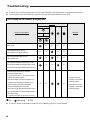
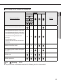
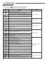
1
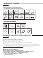
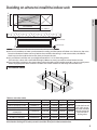
Contents Preparation for installation . .............................................................................................................................................................................................. 3 Deciding on where to install the indoor unit . .......................................................................................................................................................... 4 Indoor unit installation . ................................................................................................................................................................................................... 12 Purging the unit .................................................................................................................................................................................................................. 13 Connecting the refrigerant pipe . ................................................................................................................................................................................ 14 Cutting/Flaring the pipes ................................................................................................................................................................................................ 15 Performing leak test & insulation ................................................................................................................................................................................ 16 Drainpipe and drain hose installation . ..................................................................................................................................................................... 17 Connecting the connection cord ................................................................................................................................................................................ 19 Adjusting air flow.................................................................................................................................................................................................................. 20 Setting the indoor unit option code............................................................................................................................................................................ 22 Setting an indoor unit address and installation option...................................................................................................................................... 23 Troubleshooting . ................................................................................................................................................................................................................ 26 Safety precautions Carefully follow the precautions listed below because they are essential to guarantee the safety of the equipment. WARNING • Always disconnect the air conditioner from the power supply before servicing it or accessing its internal components. • Verify that installation and testing operations are performed by qualified personnel. • Verify that the air conditioner is not installed in an easily accessible area. General information Carefully read the content of this manual before installing the air conditioner and store the manual in a safe place in order to be able to use it as reference after installation. For maximum safety, installers should always carefully read the following warnings. Store the operation and installation manual in a safe location and remember to hand it over to the new owner if the air conditioner is sold or transferred. This manual explains how to install an indoor unit with a split system with two SAMSUNG units. The use of other types of units with different control systems may damage the units and invalidate the warranty. The manufacturer shall not be responsible for damages arising from the use of non compliant units. The air conditioner is compliant with the requirements of the Low Voltage Directive (72/23/EEC), the EMC Directive (89/336/EEC) and the Directive on pressurized equipment (97/23/EEC). The manufacturer shall not be responsible for damage originating from unauthorized changes or the improper connection of electric and requirements set forth in the “Operating limits” table, included in the manual, shall immediately invalidate the warranty. The air conditioner should be used only for the applications for which it has been designed: the indoor unit is not suitable to be installed in areas used for laundry. Do not use the units if damaged. If problems occur, switch the unit off and disconnect it from the power supply. In order to prevent electric shocks, fires or injuries, always stop the unit, disable the protection switch and contact SAMSUNG’s technical support if the unit produces smoke, if the power cable is hot or damaged or if the unit is very noisy. Always remember to inspect the unit, electric connections, refrigerant tubes and protections regularly. These operations should be performed by qualified personnel only. The unit contains moving parts, which should always be kept out of the reach of children. Do not attempt to repair, move, alter or reinstall the unit. If performed by unauthorized personnel, these operations may cause electric shocks or fires. Do not place containers with liquids or other objects on the unit. All the materials used for the manufacture and packaging of the air conditioner are recyclable. The packing material and exhaust batteries of the remote controller(optional) must be disposed of in accordance with current laws. The air conditioner contains a refrigerant that has to be disposed of as special waste. At the end of its life cycle, the air conditioner must be disposed of in authorized centers or returned to the retailer so that it can be disposed of correctly and safely. Installing the unit IMPORTANT: When installing the unit, always remember to connect first the refrigerant tubes, then the electrical lines. Always disassemble the electric lines before the refrigerant tubes. Upon receipt, inspect the product to verify that it has not been damaged during transport. If the product appears damaged, DO NOT INSTALL it and immediately report the damage to the carrier or retailer (if the installer or the authorized technician has collected the material from the retailer.) After completing the installation, always carry out a functional test and provide the instructions on how to operate the air conditioner to the user. Do not use the air conditioner in environments with hazardous substances or close to equipment that release free flames to avoid the occurrence of fires, explosions or injuries. 2 Our units should be installed in compliance with the spaces shown in the installation manual, to ensure accessibility from both sides and allow repairs or maintenance operations to be carried out. The unit’s components should be accessible and easy to disassemble without endangering people and objects. For this reason, when provisions of the installation manual are not complied with, the cost required to access and repair the units (in SAFETY CONDITIONS, as set out in prevailing regulations) with harnesses, ladders, scaffolding or any other elevation system will NOT be considered part of the warranty and will be charged to the end customer. Power supply line, fuse or circuit breaker - Do not connect the earth wire to the gas pipe, water pipe, lighting rod or telephone wire. If earthing is not complete, electric shock or fire may occur. Install the circuit breaker. - If the circuit breaker is not installed, electric shock or fire may occur. Make sure that the condensed water dripping from the drain hose runs out properly and safely. Install the power cable and communication cable of the indoor and outdoor unit at least 1m away from the electric appliance. Install the indoor unit away from lighting apparatus using the ballast. - If you use the wireless remote control, reception error may occur due to the ballast of the lighting apparatus. Do not install the air conditioner in following places. - Place where there is mineral oil or arsenic acid. Resin parts flame and the accessories may drop or water may leak. The capacity of the heat exchanger may reduce or the air conditioner may be out of order. - The place where corrosive gas such as sulfurous acid gas generates from the vent pipe or air outlet. The copper pipe or connection pipe may corrode and refrigerant may leak. - The place where there is a machine that generates electromagnetic waves. The air conditioner may not operate normally due to control system. - The place where there is a danger of existing combustible gas, carbon fiber or flammable dust. The place where thinner or gasoline is handled. Gas may leak and it may cause fire. Preparation for installation When deciding on the location of the air conditioner with the owner, the following restrictions must be taken into account. General Do NOT install the air conditioner in a location where it will come into contact with the following elements : Combustible gases Saline air Machine oil Sulphide gas Special environmental conditions If you must install the unit in such conditions, first consult your dealer. Avoid installing the air conditioner : In areas where it is exposed to direct sunlight. Close to heat sources. In damp areas or locations where it could come into contact with water. (for example rooms used for laundry) In areas where curtains and furniture could affect the supply and discharge of air. Without leaving the required minimum space around the unit. (as shown in the drawing) In scarcely ventilated areas. On surfaces that are unable to support the weight of the unit without deforming, breaking or causing vibrations during the use of the air conditioner. In a position that does not enable the condensate drainage pipe to be correctly installed. (at the end of the installation. It is always essential to check the efficiency of the drainage system) 3 ENGLISH Always make sure that the power supply is compliant with current safety standards. Always install the air conditioner in compliance with current local safety standards. Always verify that a suitable grounding connection is available. Verify that the voltage and frequency of the power supply comply with the specifications and that the installed power is sufficient to ensure the operation of any other domestic appliance connected to the same electric lines. Always verify that the cut-off and protection switches are suitably dimensioned. Verify that the air conditioner is connected to the power supply in accordance with the instructions provided in the wiring diagram included in the manual. Always verify that electric connections (cable entry, section of leads, protections…) are compliant with the electric specifications and with the instructions provided in the wiring scheme. Always verify that all connections comply with the standards applicable to the installation of air conditioners. Devices disconnected from the power supply should be completely disconnected in the condition of overvoltage category. Make sure that you earth the cables. Preparation for installation Accessories The following accessories are supplied with the indoor unit. The type and quantity may differ depending on the specifications. User’s manual Installation manual Pattern sheet Insulation drain Insulation cover pipe Insulation cover pipe 2 Insulation pipe Insulation drain pipe Clamp hose Rubber Cable-tie Flexible hose Wired remote control accessories Wired remote control Cable-tie Cable clamp M4x16 tapped screw Indoor unit power drawing cable Communication cable of the wired remote control Wire joint User’s manual Installation manual Deciding on where to install the indoor unit Indoor unit There must be no obstacles near the air inlet and outlet. Install the indoor unit on a ceiling that can support its weight. Maintain sufficient clearance around the indoor unit. Make sure that the water dripping from the drain hose runs away correctly and safely. The indoor unit must be installed in this way, that they are out of public access. (Not touchable by the users) After connecting a chamber, insulate the connection part between the indoor unit and the chamber with t10 or thicker insulation. Otherwise, there can be air leak or dew from the connection part. Space requirements for installation & service Construction Standard for Inspection Hole 1) In case, the ceiling is tex tile, Inspection hole dose not need. 2) In case, the ceiling is plaster board, Inspection hole depends on Inside height of the ceiing. a. Height is more than 3.28ft(1m) : Only "B" [Inspection for PBA] is applied. b. Height is less than 3.28ft(1m) : Both "A"&"B" are applied. c. "A"&"B" are inspection holes . 4 ENGLISH Unit Depth(D)+50mm Deciding on where to install the indoor unit Unit Width(W) "A"=W+100mm "B"=500mm 20mm or more 20mm or more You must have20mm or more space between the ceiling and the bottom of indoor unit. Otherwise, the noise from the vibration of indoor unit may bother the user.When the ceiling is under construction, the hole for check-up must be made to take service, clean and repair the unit. It is possible to install the unit at an height of between 2.2~2.5m from the ground, if the unit has a duct with a well defined lenght (300mm or more), to avoid fan motor blower contact. If you install the cassette or duct type indoor unit on the ceiling with humidity over 80%, you must apply extra 10mm of polyethylene foam or other insulation with similar material on the body of the indoor unit. Insulation Guide B D Back Front A Thickness: more than 10mm Indoor Unit NS035LDXEA C 900x600x199 A 900x600 B 900x600 C 600*199 D 600x199 NS052LDXEA/NS071LDXEA NS052SDXEA NS071SDXEA / NS090SSXE NS100SSXE NS090SDXEA 1100x600x199 1100x600 1100x600 600x199 600x199 900x480x260 900x480 900x480 480x260 1150x480x260 1150x480 1150x480 480X260 1150x480x320 1150x480 1150x480 480x320 NS100/125/140SDXEA 1200x650x360 1200x650 1200x650 Front/Back Insulate the front and back side in proper size at the same time 480X260 when insulating the suction duct and discharge duct. 480x320 480x260 650x360 650x360 Insulate the end of the pipe and some curved area by using separate insulator. Insulate the discharge and suction part at the same time when you insulate connection duct. 5 Deciding on where to install the indoor unit AA Drawing of the indoor unit Unit:mm NS035LDXEA 3 256=768 71 100 10 11.9 28 28 600 477(Suspension position) 938.4 (Suspension position) 8 100=800 860 (Air outlet duct flange) 22-ø3.2 hole (Air around) 900 650 Inspection hole 900 1000 6 No. Name 1 2 3 4 5 6 7 8 Liquid pipe connection Gas pipe connection Drain pipe connection Drain pipe connection Power supply connection Air discharge flange Air filter Hook 30.5 OD32 72.5 55 100 151.6 199 145.5 115.5 18 500 Discharge side 182 246 333 Description ø6.35(1/4") ø9.52(3/8") OD32 ID26(without drain pump) Using drain pump (Optional) M8~M10 Suction side Unit:mm NS052LDXEA/NS071LDXEA ENGLISH (Suspension position) (Suspension position) (Air outlet duct flange) hole (Air around) 650 Inspection hole 1100 1200 500 Discharge side No. Name 1 2 3 4 5 6 7 8 Liquid pipe connection Gas pipe connection Drain pipe connection Drain pipe connection Power supply connection Air discharge flange Air filter Hook Suction side Description ø6.35(1/4") 052: ø12.70(1/2"); 071: ø15.88(5/8") OD32 ID26(without drain pump) Using drain pump (Optional) M8~M10 7 Deciding on where to install the indoor unit AA Drawing of the indoor unit Unit : mm NS052SDXEA 397 (Suspension position) 900 1000 135x5=675 7 87 500 97 900 844 (Air outlet duct flange) 6 936 (Suspension position) 530 480 8 222 Discharge side 185 90 260 Inspection hole 2 1 5 No. 1 2 3 4 5 6 7 8 8 4 3 76 132 139 Name Liquid pipe connection Gas pipe connection Drain pipe connection Drain pipe connection Power supply connection Air discharge flange Air filter Hook Suction side Description ø6.35(1/4"); ø12.70(1/2") OD32 ID26(without drain pump) Using drain pump (Optional) M8~M10 77 117 12 NS071SDXEA NS090SSXE NS100SSXE Unit : mm ENGLISH 530 480 18-Ø3.2 hole (Air around) 1150 97 1250 1188 (Suspension position) 1150 904 (Air outlet duct flange) 6X135=810 397 (Suspension position) 220 500 90 90 260 185 Inspection hole 67 117 Discharge side ODØ32 No. 1 2 3 4 5 6 7 8 Suction side 76 132 144 Name Liquid pipe connection Gas pipe connection Drain pipe connection Drain pipe connection Power supply connection Air discharge flange Air filter Hook Description 071:ø6.35(1/4");090/100:ø9.52(3/8") ø15.88(5/8") OD32 ID26(without drain pump) Using drain pump (Optional) M8~M10 9 Deciding on where to install the indoor unit AA Drawing of the indoor unit Unit : mm NS090SDXEA 530 500 102 1150 1250 (Air outlet duct flange) (Suspension position) (Suspension position) Discharge side 10 Suction side Inspection hole No. Name Description 1 2 3 4 5 6 7 8 Liquid pipe connection Gas pipe connection Drain pipe connection Drain pipe connection Power supply connection Air discharge flange Air filter Hook ø9.52(3/8") ø15.88(5/8") OD32 ID26(without drain pump) Using drain pump (Optional) M8~M10 NS100SDXEA NS125SDXEA NS140SDXEA Unit : mm ENGLISH 700 650 1300 500 102 1200 1000 (Air outlet duct flange) 1236 (Suspension position) 534 (Suspension position) Discharge side Suction side Inspection hole No. Name Description 1 2 3 4 5 6 7 8 Liquid pipe connection Gas pipe connection Drain pipe connection Drain pipe connection Power supply connection Air discharge flange Air filter Hook ø9.52(3/8") ø15.88(5/8") OD32 ID26(without drain pump) Using drain pump (Optional) M8~M10 11 Indoor unit installation AA When deciding on the location of the air conditioner with the owner, the following restrictions must be taken into account. 1 Place the pattern sheet on the ceiling at the spot where you want to install the indoor unit. •Since the diagram is made of paper, it may shrink or stretch slightly due to temperature or humidity. For this reason, before drilling the holes maintain the correct dimensions between the markings. Concrete 2 Insert bolt anchors. Use existing ceiling supports or construct a suitable support as shown in figure. 3 Install the suspension bolts depending on the ceiling type. Insert Hole in anchor hole in plug Suspension bolt(M8)-field supply •Ensure that the ceiling is strong enough to support the weight of the indoor unit. Before hanging the unit, test the strength of each attached suspension bolt. •If the length of suspension bolt is more than 1.5m, it is required to prevent vibration. • If this is not possible, create an opening on the false ceiling in order to be able to use it to perform the required operations on the indoor unit. 4 Ceiling support Screw eight nuts to the suspension bolts making space for hanging the indoor unit. •You must install all the suspension rods. 5 Hang the indoor unit to the suspension bolts between two nuts. •Piping must be laid and connected inside the ceiling when suspending the unit. If the ceiling is already constructed, lay the piping into position for connection to the unit before placing the unit inside the ceiling. 6 Screw the nuts to suspend the unit. 7 Adjust level of the unit by using measurement plate for all 4 sides. •For proper drainage of condensate, give a "A"mm slant to the left or right side of the unit which will be connected with the drain hose, as shown in the figure. Make a tilt when you wish to install the drain pump, too. When the drain hose is installed to the right. Amm Drain hose port Model NS035/052/071LDXEA NS052/071/090/100/125/140SDXEA NS090/100SSXE 12 A 10mm 3mm Purging the unit AA From factory the unit is supplied and set with a pre-charge of nitrogen gas. (insert gas) Therefore, all insert gas must be purged before connecting the assembly piping. NS035/052/071LDXEA Unscrew the pinch pipe at the end of each refrigerant pipe. •To prevent dirt or foreign objects from getting into the pipes during installation, do NOT remove the pinch pipe completely until you are ready to connect the piping. • Connect the indoor and outdoor units using pipes with flared connections(not supplied). For the lines, use insulated, unwelded, degreased and deoxidized copper pipe (Cu DHP type to ISO 1337 or UNI EN 12735-1), suitable for operating pressures of at least 4200kPa and for a burst pressure of at least 20700kPa. Copper pipe for hydrosanitary applications is completely unsuitable. • For sizing and limits (height difference, line length, max. bends, refrigerant charge, etc.) see the outdoor unit installation manual. • All refrigerant connection must be accessible, in order to permit either unit maintenance or removing it completely. Liquid refrigerant port Gas refrigerant port NS052/071/090/100/125/140SDXEA NS090/100SSXE Liquid refrigerant port Gas refrigerant port 13 ENGLISH Result : All inert gas escapes from the indoor unit. Connecting the refrigerant pipe There are two refrigerant pipes of different diameters : A smaller one for the liquid refrigerant A larger one for the gas refrigerant The inside of copper pipe must be clean & has no dust 1. Remove the pinch pipe on the pipes and connect the assembly pipes to each pipe, tightening the nuts, first manually and then with a torque wrench, a spanner applying the following torque. Refrigerant oil Torque wrench Spanner Flare nut Union Outer Diameter (D) Torque (N•m) ø6.35 mm ø9.52 mm ø12.70 mm ø15.88 mm ø19.05 mm 18 42 55 65 100 •If the pipes must be shortened refer to page 15. 2. Must use insulator which is thick enough to cover the refrigerant tube to protect the condensate water on the outside of pipe falling onto the floor and the efficiency of the unit will be better. 3. Cut off any excess foam insulation. 4. Be sure that there must be no crack or wave on the bended area. 5. It would be necessary to double the insulation thickness(10mm or more) to prevent condensation even on the insulator when if the installed area is warm and humid. 6. Do not use joints or extensions for the pipes that connect the indoor and outdoor unit. The only permitted connections are those for which the units are designed. NS052/071/090/100/125/140SDXEA NS035/052/071LDXEA NS090/100SSXE Drain hose connection port Liquid refrigerant port Liquid refrigerant port 14 Gas refrigerant port Gas refrigerant port Drain hose connection port Cutting/Flaring the pipes 1. Make sure that you have the required tools available. (pipe cutter, reamer, flaring tool and pipe holder) 2. If you wish to shorten the pipes, cut it with a pipe cutter, taking care to ensure that the cut edge remains at a 90° angle with the side of the pipe. Refer to the illustrations below for examples of edges cut correctly and incorrectly. Oblique Rough ENGLISH Pipe cutter Burr Pipe 3. To prevent any gas from leaking out, remove all burrs at the cut edge of the pipe, using a reamer. 4. Slide a flare nut on to the pipe and modify the flare. Outer Diameter (D) Pipe Flare ø6.35 mm ø9.52 mm ø12.70 mm ø15.88 mm ø19.05 mm Depth (A) 1.3 mm 1.8 mm 2.0 mm 2.2 mm 2.2 mm 5. Check that the flaring is correct, referring to the illustrations below for examples of incorrect flaring. Correct Inclined Damaged Surface Cracked Uneven Thickness 6. Align the pipes and tighten the flare nuts first manually and then with a torque wrench, applying the following torque. Valve 1/4" 3/8" 1/2" 5/8" 3/4" Flare nut Valve cap Pressure port cap Valve needle Pressure port Wrench(mm) N•m Wrench(mm) N•m Wrench(mm) N•m Wrench(mm) N•m Wrench(mm) N•m 17 18 23 20 18 16~18 Allen(hex.) 5 9 0.34 22 42 23 20 18 16~18 Allen(hex.) 5 9 0.34 26 55 29 40 18 16~18 Allen(hex.) 5 13 0.34 29 65 29 40 18 16~18 Allen(hex.) 5 13 0.34 36 100 38 40 18 16~18 Allen(hex.) 5 13 0.34 • If the pipes require brazing ensure that OFN (Oxygen Free Nitrogen) is flowing through the system. • Nitrogen blowing pressure range is 0.02 ~ 0.05MPa. 15 Performing leak test & insulation AA NS035/052/071LDXEA Leak test LEAK TEST WITH NITROGEN (before opening valves) In order to detect basic refrigerant leaks, before recreating the vacuum and recirculating the R-410A, it’s responsable of installer to pressurize the whole system with nitrogen (using a cylinder with pressure reducer) at a pressure above 30 bar (gauge). LEAK TEST WITH R-410A (after opening valves) Before opening valves, discharge all the nitrogen into the system and create vacuum. After opening valves check leaks using a leak detector for refrigerant R-410A. NS052/071/090/100/125/140SDXEA NS090/100SSXE • Discharge all the nitrogen to create a vacuum and charge the system. Insulation Once you have checked that there are no leaks in the system, you can insulate the piping and hose. 1 To avoid condensation problems, place T13.0 or thicker Acrylonitrile Butadien Rubber separately around each refrigerant pipe. No gap •Always make the seam of pipes face upwards. • The insulation has to be produced in full compliance of European regulation reg. EEC / EU 2037/ 2000 that requires the use of sheaths insulation form without using CFC and HCFC gases for health and the environment. 2 Wind insulating tape around the pipes and drain hose avoiding to compress the insulation too much. 3 Finish wrapping insulating tape around the rest of the pipes leading to the outdoor unit. 4 The pipes and electrical cables connecting the indoor unit with the outdoor unit must be fixed to the wall with suitable ducts. •All refrigerant connection must be accessible, in order to permit either unit maintenance or removing it completely. NBR(T13.0 or thicker) Insulation cover pipe Insulation pipe Indoor unit Be sure to overlap the insulation 5 Select the insulation of the refrigerant pipe. •Must fit tightly against Insulate the gas side and liquid side pipe referring to the thickness body without any gap. according to the pipe size. Indoor temperature of 30°C and humidity of 85% is the stan dard condition. If installing in a high humidity condition, use one grade thicker insulator by referring to the table below. If installing in an unfavorable conditions, use thicker one. Insulator’s heat-resistance temperature should be more than 120°C. 16 Pipe size Liquid pipe Ø6.35 ~ Ø9.52 Ø12.7 ~ Ø19.05 Ø6.35 Ø9.52 Ø12.70 Ø15.88 Ø19.05 Gas pipe Insulation Type (Heating/Cooling) Standard [30°C, 85%] High humidity [30°C, over 85%] EPDM, NBR 9t 9t 13t 13t 13t 19t 19t Remarks ENGLISH Pipe Internal temperature is higher than 120°C 25t When installing insulation in places and conditions below, use the same insulation that is used for high humidity conditions. <Geological condition> - High humidity places such as shoreline, hot spring, near lake or river, and ridge (when the part of the building is covered by earth and sand.) <Operation purpose condition> - Restaurant ceiling, sauna, swimming pool etc. <Building construction condition> - The ceiling frequently exposed to moisture and cooling is not covered. e.g. The pipe installed at a corridor of a dormitory and studio or near an exit that opens and closes frequently. - The place where the pipe is installed is highly humid due to the lack of ventilation system. Drainpipe and drain hose installation Care must be taken when installing the drain hose for the indoor unit to ensure that any condensate water is correctly drained outside. The drain hose can be installed to the right of the base pan. 1 Insert the flexible hose to the drain hose port. 2 • Fix the flexible hose to the indoor unit with the supplied cable clamp securely. (Use the screwdriver to fix the flexible hose securely.) Install the drain hose so that its length can be as short as possible. Internal diameter of the drain hose should be the same or slightly bigger than the external diameter of the drain hose port. Cable-tie Clamp 32mm(Inner diameter) • Inner diameter of the drain hose •Give a slightly slant to the drain hose for proper drainage of condensate. • Fix the flexible hose to the PVC with the supplied cable tie securely. 3 Flexible hose Insulation drain hose Insulation cover drain Wrap the drain hose with the insulation drain as shown in figure and secure it. 17 Drainpipe and drain hose installation AA Drainpipe Connection Without the drain pump 1. Install horizontal drainpipe with a slope of 1/100 or more and fix it by hanger space of 1.0~1.5m. 2. Install U-trap at the end of the drainpipe to prevent a nasty smell to reach the indoor unit. 3. Do not install the drainpipe to upward position. It may cause water flow back to the unit. 1~1.5m Hanger Flexible hose Horizontal drainpipe more than 1/100 slope Ceiling With the drain pump 1. The drain pipe should be installed within 300mm to 550mm from the flexible hose and then lift down 20mm or more. 2. Install horizontal drainpipe with a slope of 1/100 or more and fix it by hanger space of 1.0~1.5m. 3 Install the air vent in the horizontal drainpipe to prevent water flow back to the indoor unit. • You may not need to install it if there were proper slope in the horizontal drainpipe. 4 The flexible hose should not be installed upward position, it may cause water flow back to the indoor unit. Air vent 200mm or more 300mm or less Flexible hose 1~1.5m 20mm or more Within 300~550mm Ceiling Hanger Horizontal drainpipe more than 1/100 slope Testing the drainage Prepare a little water about 5 liter. 1 Pour water into the base pan in the indoor unit as shown in figure. 2 Confirm that the water flows out through the drain hose. 18 NS035/052/071LDXEA NS052/071/090/100/125/140SDXEA NS090/100SSXE Connecting the connection cord The indoor unit is powered by the outdoor unit by means of a H07 RN-F connection cable (or a more power model), with insulation in synthetic rubber and jacket in polychloroprene(neoprene), in accordance with the requirements of standard EN 60335-2-40. 1. Remove the screw on the electrical component box and remove the cover plate. 2. Route the connection cord through the side of the indoor unit and connect the cable to terminals; refer to the figure below. 3. Route the other end of the cable to the outdoor unit through the ceiling & the hole on the wall. 4. Reassemble the electrical component box cover, carefully tightening the screw. Wiring diagram 1 phase 1(L) 2(N) 1(L) 2(N) Indoor Unit L F2 F1 N Cable tie Indoor Power Main power cable Communication cable Cable clamp Between Indoor and Outdoor Connection cable Specifications(Common in use) Indoor Power supply Power Supply 220-240V~/50Hz Indoor Power cable 0.75~1.5mm²,3wires Max/Min(V) ±10% Communication Cable 0.75~1.25mm²,2wires For connection cable, use the grade H07RN-F or H05RN-F materials. Screws on terminal block must not be unscrewed with the torque less than 12 kgf•cm. Since it has the external power supply, refer to the outdoor unit installation manual for MAIN POWER. When installing the indoor unit in a computer room, use the double shielded(Tape aluminum / polyester braid + copper) cable of FROHH2R type. Terminal Block SPEC (Indoor) COMMUNICATION : M4 SCREW 9.5 8.4 10 8.4 9.5 10 AC POWER : M4 SCREW 19 ENGLISH •Always remember to connect the refrigerant pipes before performing the electric connections. When disconnecting the system, always disconnect the electric cables before disconnecting the refrigerant pipes. •Always remember to connect the air conditioner to the grounding system before performing the electric connections. Adjusting air flow AA E. S. P(External Static Pressure) setting for phase control motor With its phase control motor, you can adjust the indoor unit fan speed depending on the installation condition. If the external static pressure is high so that the duct becomes longer or if the external static pressure is low so that the duct becomes shorter, adjust the fan speed by referring the following table. Static Pressure (mmAq) 0 2 2.5 4 NS071LDXEA 011037 -156175 -274750 -370010 - 011037 -1563F7 -274750 -370010 011037 -1163FB -274750 -370010 - NS071SDXEA 011017 -1163E7274750 -370010 011037 -11613A274750 -370010 - 011037 -11618C274750 -370010 011047 -116203 -274750 -370010 NS090SDXEA 011044 -1560D3 -275A64 -350000 011044 -156265 -275A64 -350000 - 011044 -156299 -275A64 -350000 011044 -156083 -276470 -370000 011034 -15613B NS100SSXEA -276470 -370000 011044 -157083 NS125SDXEA -277D8C -370000 011044 -1560A4 -276470 -370000 011034 -1561AF -276470 -370000 011044 -1570A4 -277D8C -370000 011044 -1670A3 -278CA0 -370000 011034 -15613B -275A64 -370000 011034 -15613B -275A64 -370010 011034 -15613B -276470 -370010 011044 -1670C4 -278CA0 -370000 011034 -1561AF -275A64 -370000 011034 -1561AF -275A64 -370010 011034 -1561AF -276470 -370010 Model NS090SSXEA NS090SSXEX NS100SSXEX 20 8 10 12 14 - - - 011047 011047 -1162FF -1163FD-274750 274750 -370010 -370010 - - 011044 -1562FA -275A64 -350000 011044 011044 -1562FB -1562FB -275A64 -275A64 -350000 -350000 - - 011044 -1560E8 -276470 -370000 011044 -156293 -276470 -370000 011044 -1570C6 -277D8C -370000 011044 -1560F8 -276470 -370000 011044 -1562F6 -276470 -370000 011044 -1570F8 -277D8C -370000 011044 -15621A -276470 -370000 011044 -1562F8 -276470 -370000 011044 -15721A -277D8C -370000 011044 -15626C -276470 -370000 011044 -15629E -276470 -370000 011044 -1563C0 -276470 -370000 - - - 011044 -1670E6 -278CA0 -370000 011044 -156293 -275A64 -370000 011044156293275A64370010 011044156293276470370010 011044 -167208 -278CA0 -370000 011044 -1562F6 -275A64 -370000 011044 -1562F6 -275A64 -370010 011044 -1562F6 -276470 -370010 011044 011044 011044 -16722A -16728C -1672FE -278CA0 -278CA0 -278CA0 -370000 -370000 -370000 011044 -1562F8 -275A64 -370000 011044 -1562F8 -275A64 -370010 011044 -1562F8 -276470 -370010 Option code for indoor unit NS100SDXEA NS140SDXEA 6 - - - - - - - - 011044 011044 011044 -15726C -15729E -1573C0 -277D8C -277D8C -277D8C -370000 -370000 -370000 011044 -1673F0 -278CA0 -370000 - - - 0 Model NS035LDXEA NS052LDXEA NS052SDXEA 2.5 4 5 8 - - - - 011034 -196106 -27343C -370010 011034 -19630D -27343C -370010 ENGLISH Static Pressure (mmAq) Option code for indoor unit 011037 -136153 -272328 -370010 011014 -156360 -27343C -370010 011014 -19625E -27343C -370010 011037 -1361DB -272328 -370010 011014 -1563E6 -27343C -370010 011014 -1963A2 -27343C -370010 011047 -136220 -272328 -370010 011034 -15616C -27343C -370010 - • represents E. S. P(External Static Pressure) range of factory setting. You don’t have to adjust the fan speed separately if the external static pressure of the installation place is in . When it is out of , input the appropriate option code. • If you input the inappropriate option code, error may occur or the air conditioner is out of order. The option code must be inputted correctly by the installation specialist or service agent. 21 Setting the indoor unit option code AA Setting the option code with wireless remocon is availble if receiver kit is installed. Please use the proper wireless remocon such as MR-DH00 which set 24 digit option code. Following is the instruction of setting option code with wired remocon(WMR-WH02). In order to set the indoor unit option code using the wired remote controller, hold down the buttons at the same time for 5 seconds. and 1 The menu will display . Press the button to enter the indoor unit option code mode. • The first digit represents the page number and the remaining five digits are option codes. 2 Press the button to change the page. You can change the page from 0 to 3. Page No. 3 Press the code in order. buttons and the button to set the option • The option code which is currently setting will flicker. Option code 4 Press the button to save the changed setting. You will move to the menu selection display. • Press the button anytime during setup to exit without setting. •O ption code will not be applied if you don’t press the button. • S etting indoor unit option code is only possible in Master wired remote controller. You can only check the indoor unit option code in Slave wired remote controller. • Setting indoor unit option code is possible when one indoor unit is connected. If more than 2 indoor units are connected, you can only check the Master indoor unit option code. 22 Setting an indoor unit address and installation option AA ENGLISH Set the indoor unit address and installation option with remote controller option. Set the each option separately since you cannot set the ADDRESS setting and indoor unit installation setting option at the same time.You need to set twice when setting indoor unit address and installation option. Setting an indoor unit address In order to check and set the indoor unit Main/Group Address using the wired remote controller, hold down the and buttons at the same time for 5 seconds. 1 2 The menu will display . Press the button and the menu will display . Press the button. The main address (decimal notation) and group address (hexadecimal notation) of currently set indoor unit will be displayed. Menu No. 3 Press the buttons and the indoor unit Main/Group Address. 4 Press the button to set the button. Wired remote controller sends data to an indoor unit. 5 Press the button to exit. Checking the Indoor unit main address Setting the Indoor unit main address Indoor unit RMC address You will move to the menu selection display. • Press the button anytime during setup to exit without setting. • Setting main/group address of an indoor unit is available only with a master wired remote controller. 23 Setting an indoor unit address and installation option AA Setting an indoor unit installation option In order to check and set the indoor unit DIP option code using the wired remote controller, hold and buttons at the same time for 5 seconds. down the 1 The menu will display Press the 2 Press the . button until is displayed. button. The current DIP option code set in an indoor unit will be displayed. 3 Press button and change the page number. The total option codes are 24digits.you can set six digits at a time and it is distinguished by page number(0,1,2,3). 24 Page number DIP OPTION CODE Option No. : 02XXXX-1XXXXX-2XXXXX-3XXXXX Option SEG1 Indication and Details PAGE SEG4 Use of external temperature sensor MODE Indication Details Indication Details 0 SEG3 RESERVED 0 1 Option Explanation SEG7 SEG8 SEG9 PAGE Use of drain pump HOT COIL Indication Details Indication Details Indication Details 0 Disuse 0 Disuse Indication 1 Use 1 Use and Details 1 Use + 2 3minute delay Option SEG13 SEG14 SEG15 Use of external Setting the output of Explanation PAGE control external control Indication Details Indication Details Indication Details Thermo Disuse 0 0 on Indication ON/OFF and Details 2 1 Control Operation 1 on OFF 2 Control Option SEG19 SEG20 SEG21 Individual control Explanation PAGE of a remote controller Indication Details Indication Details RESERVED 0 or 1 Indoor 1 Indication Indoor 2 2 and Details 3 Indoor 3 3 Indoor 4 4 buttons and the Indoor unit DIP option code. 5 Press the Disuse Use SEG10 RESERVED SEG6 Use of central control Indication Details Indication 2 4 Press the SEG5 0 1 RESERVED Details Disuse Use SEG11 RESERVED SEG12 Master / Slave Indication Details 0 slave 1 master - SEG16 SEG17 Buzzer control Indication RESERVED ENGLISH Explanation SEG2 0 1 Details Use of buzzer Non use of buzzer - SEG18 Number of hours using filter Indication Details 2 1000 Hour 6 2000 Hour SEG22 SEG23 SEG24 RESERVED RESERVED RESERVED button to set the button. Wired remote controller sends data to an indoor unit. 6 Press the button to exit. You will move to the menu selection display. • Press the button anytime during setup to exit without setting. • Setting an indoor unit DIP option code is available only with a master wired remote controller. • Setting an indoor unit DIP option code is available when there is one on one connection between a wired remote controller and an indoor unit. • Indoor unit DIP option code will not be applied if you don’t press the button. 25 Troubleshooting AA If an error occurs during the operation, one or more LED flickers and the operation is stopped except the LED. If you re-operate the air conditioner, it operates normally at first, then detect an error again. LED Display on the receiver & display unit Indicators Concealed Type Abnormal conditions Green Remarks Red Standard Type Power reset X Error of temperature sensor in the indoor unit (Open/Short) X Error of heat exchanger sensor in the indoor unit X X X X X X X X X Error of the outdoor temperature sensor Error of the condensor temperature sensor X X X Error of the discharge temperature sensor 1. No communication for 2 minutes between indoor units (Communication error for more than 2 minutes) 2. Indoor unit receiving the communication error from outdoor unit 3. Outdoor unit tracking 3 minutes error 4. When sending the communication error from the outdoor unit, the mismatching of the communication numbers and installed numbers after completion of tracking. (Communication error for more than 2 minutes) On Flickering X X X X Off If you turn off the air conditioner when the LED is flickering, the LED is also turned off. 26 1. Indoor unit error (Display is unrelated with operation) 2. Outdoor unit error (Display is unrelated with operation) LED Display on the receiver & display unit ENGLISH Indicators Concealed Type Abnormal conditions Green Remarks Red Standard Type Communication error between indoor units X X X 1. Error of electronic expansion valve close 2. Error of electronic expansion valve open 3. 2’nd detection of high temperature cond 4. 2’nd detection of high temperature discharge X X Detection of the float switch X X Error of setting option switches for optional accessories X X 5. Error of reverse phase 6. Compressor down due to 6th detection of freezing EEPROM error X X X X EEPROM option error On Flickering X Off If you turn off the air conditioner when the LED is flickering, the LED is also turned off. 27 Troubleshooting AA Wired remote control If an error occurs, is displayed on the wired remote control. If you would like to see an error code, press the Test button. Display Explanation Remark Indoor unit Communication Error Indoor/Outdoor unit Communication Time Out Error 60 Packet Over data Indoor unit is not connected Communication Error Communication Error between Outdoor Main and Inverter Micom (Occurred after 1 minute detection in Main and Inverter) Indoor Temp. Sensor (Open/Short Error) Indoor Unit Eva in Sensor (Open/Short Error) Indoor Sensor Error Indoor Unit Eva in Sensor Separation Outdoor Temp. Sensor Error (Open/Short Error) COND Temp. Sensor Error (Open/Short Error) Inverter Compressor Discharge Temp. sensor Error (Open/Short Error) Outdoor Sensor Error Power cable miss connection error Indoor Float S/W 2nd Detection Outdoor unit - indoor unit communication wire miss connection (Connected to Power terminal) Outdoor unit refrigerant Full leakage (Gas leak) Self Diagnosys Error Outdoor Fan 1 Error Outdoor Fan 2 Error Discharge over temperature [Inverter] Compressor starting error Primary Current Over Trip error [Inverter] DC PEAK error(O.C) [Inverter] Compressor Rotation error [Inverter] Current Sensor error Outdoor Unit Protection Control Error [Inverter] DC LINK Sensor error [Inverter] EEPROM Read/Write Error [Inverter] Heatsink temperature over Error Outdoor unit Capacity Setup option error Communication error between Indoor unit and wired remote control Communication error between Master and Slave wired remote control COM1/COM2 Cross-installed error Error of setting option for wired remote control COM2 28 Wired Remote Control Error Memo ENGLISH 29 "EEE Yönetmeliğine Uygundur" "This EEE is compliant with RoHS" Duct Type Series NSLDXEA NSSDXE NSSSXE Air Conditioner installation manual This manual is made with 100% recycled paper. imagine the possibilities Thank you for purchasing this Samsung product. To receive more complete service, please register your product at www.samsung.com/register E S F I P D G DB98-32737A-1