1
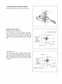
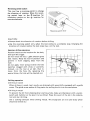
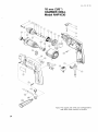
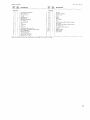
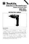
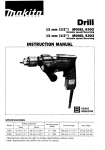
Hammer Drill
10 mm (3/8") MODEL NHPl030
Variable Speed I Reversing
INSTRUCTION MANUAL
DOUBLE
INSULATION
SPEC IFICAT ION S
Capacities
Metal
10"
(318")
I
I
Wood
I
Concrete
18mm
1314")
1
10"
(318")
I
I
I
No load
speed
(RPM)
-
2,700
I
I
Blows
per
minute
~
29,700
I
I
Overall
length
270"
(10-518")
* Manufacturer reserves the right t o change specifications without notice.
* Note: Specifications may differ from country t o country.
1
I
Net
weight
1.6 kg
(3.5 Ibs)
IMPORTANT
SAFETY INSTRUCTIONS
(For All Tools)
WARNING: WHEN USING ELECTRIC TOOLS, BASIC SAFETY
PRECAUTIONS SHOULD ALWAYS BE FOLLOWED TO REDUCE
THE RISK OF FIRE, ELECTRIC SHOCK, AND PERSONAL
INJURY, INCLUDING THE FOLLOWING:
READ ALL INSTRUCTIONS.
1. KEEP WORK AREA CLEAN. Cluttered areas and benches invite injuries.
2. CONSIDER WORK AREA ENVIRONMENT. Don't use power tools in damp
or wet locations. Keep work area well lit. Don't expose power tools t o rain.
Don't use tool in presence of flammable liquids or gases.
3. KEEP CHILDREN AWAY. All visitors should be kept away from work area.
Don't let visitors contact tool or extension cord.
4.STORE IDLE TOOLS. When not in use, tools should be stored in dry, and high
or locked-up place
-
out of reach of children.
5 . DON'T FORCE TOOL. It will do the job better and safer at the rate for which
it was intended.
6. USE RIGHT TOOL. Don't force small tool or attachment t o do the job of a
heavy-duty tool. Don't use tool for purpose not intended; for example, don't
use circular saw for cutting tree limbs or logs.
7 . DRESS PROPERLY. Don't wear loose clothing or jewelry. They can be caught
in moving parts. Rubber gloves and non-skid footwear are recommended
when working outdoors. Wear protective hair covering t o contain long hair.
8 . USE SAFETY GLASSES. Also use face or dust mask if cutting operation is
dusty.
9. DON'T ABUSE CORD. Never carry tool by cord or yank it t o disconnect from
receptacle. Keep cord from heat, oil, and sharp edges.
I O . SECURE WORK. Use clamps or a vise t o hold work. It's safer than using
your hand and it frees both hands t o operate tool.
11. DON'T OVERREACH. Keep proper footing and balance at all times.
12. MAINTAIN TOOLS WITH CARE. Keep tools sharp and clean for better and
safer performance. Follow instructions for lubricating and changing accessories. Inspect tool cords periodically and if damaged, have repaired by authorized service facility. Inspect extension cords periodically and replace if
damaged. Keep handles dry, clean, and free from oil and grease.
13. DISCONNECT TOOLS. When not in use, before servicing, and when changing accessories, such as blades, bits, cutters.
2
14. REMOVE ADJUSTING KEYS AND WRENCHES. Form habit of checking t o
see that keys and adjusting wrenches are removed from tool before turning
it on.
15. AVOID UNINTENTIONAL STARTING. Don't carry tool with finger on switch.
Be sure switch is OFF when plugging in.
16. EXTENSION CORDS. Make sure your extension cord is in good condition.
When using an extension cord, be sure t o use one heavy enough t o carry
the current your product will draw. A n undersized cord will cause a drop
in line voltage resulting in loss of power and overheating. Table 1 shows the
correct size t o use depending on cord length and nameplate ampere rating.
If in doubt, use the next heavier gage. The smaller the gage number, the
heavier the cord.
TABLE 1
MINIMUM GAGE FOR CORD SETS
Total Length of Cord in Feet
I
0 - 25
I
26 - 50
Ampere Rating
More
Not More
Than
Than
0
6
10
12
-
6
10
12
16
I
51 - 100
I
101 - 150
A W G
18
18
16
14
16
16
16
12
;:
I
14
12
14
12
Not Recommended
17. OUTDOOR USE EXTENSION CORDS. When tool is used outdoors, use only
extension cords intended for use outdoors and so marked.
18. STAY ALERT. Watch what you are doing, use common sense. Don't operate
tool when you are tired.
19. CHECK DAMAGED PARTS. Before further use of the tool, a guard or other
part that is damaged should be carefully checked t o determine that it will
operate properly and perform its intended function. Check for alignment of
moving parts, binding of moving parts, breakage of parts, mounting, and any
other conditions that may affect its operation. A guard or other part that
is damaged should be properly repaired or replaced by an authorized service center unless otherwise indicated elsewhere in this instruction manual.
Have defective switches replaced by authorized service center. Don't use
tool if switch does not turn it o n and off.
20. GUARD AGAINST ELECTRIC SHOCK. Prevent body contact w i t h grounded
surfaces. For example; pipes, radiators, ranges, refrigerator enclosures.
21. REPLACEMENT PARTS. When servicing, use only identical replacement parts.
22. POLARIZED PLUGS. To reduce the risk of electric shock, this equipment has
a polarized plug (one blade is wider than the other). This plug will fit in a
polarized outlet only one way. If the plug does not fit fully in the outlet,
reverse the plug. If it still does not fit, contact a qualified electrician t o install
the proper outlet. Do not change the plug in any way.
3
VOLTAGE WARNING: Before connecting the tool t o a power source (receptacle,
outlet, etc.) be sure the voltage supplied is the same as that specified on the
nameplate of the tool. A power source with voltage greater than that specified
for the tool can result in SERIOUS INJURY t o the user - as well as damage t o
the tool. If in doubt, DO NOT PLUG IN THE TOOL. Using a power source with
voltage less than the nameplate rating is harmful t o the motor.
ADDITIONAL SAFETY RULES
1. Wear a hard hat (safety helmet), safety glasses andlor face shield. It is also
highly recommended that you wear a dust mask, ear protectors and thickly
padded gloves.
2. Under normal operation, the tool is designed t o produce vibration. The screws
can come loose easily, causing a breakdown or accident. Check tightness of
screws carefully before operation.
3.Always be sure you have a firm footing.
Be sure no one is below when using the tool in high locations.
4. Hold the tool firmly with both hands. Always use the side grip.
5. Keep hands away from rotating parts.
6. Do not leave the tool running. Operate the tool only when hand-held.
7. When drilling into walls, floors or wherever "live" electrical wires may be
encountered, DO NOT TOUCH ANY METAL PARTS OF THE TOOL!
Hold the tool by the insulated grasping surfaces t o prevent electric shock if
you drill into a "live" wire.
8. Do not touch the bit or the workpiece immediately after operation; they may
be extremely hot and could burn your skin.
SAVE THESE INSTRUCTIONS.
4
Installing side grip (auxiliary handle)
Screw the side grip on the tool securely
\
Selecting action mode
Rotation with hammering :
For drilling in concrete, granite, tile, etc.,
turn the knob so that the c marking i s
towards the small diamond marking. Be
sure to use a concrete and masonry drilling
bit.
r
Diamond marking
Knob
Rotation only:
For drilling in wood, metal or plastic materials, turn the knob so that the
marking i s towards the small diamond marking.
Use a conventional bit for drilling in wood
o r metal.
*%*
Knob-
Diamond marking
w
5
Installing or removing drill bit
CAUTION :
Always be sure that the tool is switched off and unplugged before installing or removing
the bit.
To install the bit, place it in the chuck as
far as it will go. Tighten the chuck by hand.
Place the chuck key in each of the three
holes and tighten clockwise. Be sure to
tighten all three chuck holes evenly.
To remove the bit, turn the chuck key
counterclockwise in just one hole, then
loosen the chuck by hand.
key
\
Adjusting depth of drilling
Loosen the screw and adjust the depth
gauge to the desired depth. After adjusting,
tighten the screw.
.
Switch action
Tool speed is increased by increasing pressure on the trigger. To start the tool, simply
pull the trigger. Release the trigger to stop.
For continuous operation, pull the trigger
and then push in the lock button. To stop
the tool from the locked position, pull the
trigger fully, then release it. A speed control screw i s provided so that maximum
tool speed can be limited (variable). Turn
the speed control screw clockwise for
higher speed, and counterclockwise for
lower speed.
Lower
Speed control
Trigger switch
Hioher
&.5
-
1
w
M
/
Lock button
A=====
CAUTION :
Before plugging in the tool, always check to see that the trigger switch actuates properly
and returns to the "OFF" position when released.
6
Reversing switch action
This tool has a reversing switch to change
the direction of rotation. Move the reversing switch lever to the & position for
clockwise rotation or the & position for
counterclockwise.
CAUTION :
Always check the direction of rotation before drilling.
0
*Use the reversing switch only when the tool comes to a complete stop. Changing the
direction of rotation before the tool stops may ruin the tool.
Hammer drilling operation
Position the bit a t the location for the hole,
then pull the trigger.
Do not force the tool. Light pressure gives
best results. Keep the tool in position and
prevent it from slipping away from the
hole.
Do not apply more pressure when the hole
becomes clogged with chips or particles.
Instead, run the tool a t an idel, then remove from the hole. By repeating this
several times, the hole will be cleaned out.
Drilling operation
Drilling in wood
When drilling in wood, best results are obtained with wood drills equipped with a guide
screw. The guide screw makes drilling easier by pulling the bit into the workpiece.
0
0
Drilling in metal
To prevent the bit from slipping when starting a hole, make an indentation with a centerpunch and hammer a t the point to be drilled. Place the point of the bit in the indentation and start drilling.
Use a cutting lubricant when drilling metals. The exceptions are iron and brass which
should be drilled dry.
7
CAUTION :
*Pressing excessively on the tool will not speed up the drilling. In fact, this excessive
pressure will only serve to damage the tip of your bit, decrease the tool performance
and shorten the service life of the tool.
*There i s a tremendous force exerted on the tool/bit a t the time of hole breakthrough.
Hold the tool firmly and exert care when the bit begins to break through the workpiece.
A stuck bit can be removed simply by setting the reversing switch to reverse rotation in
order to back out. However, the tool may back out abruptly if you do not hold it firmly.
Always secure small workpieces in a vise or similar hold-down device.
MA1NTENANCE
CAUTION:
Always be sure that the tool i s switched off and unplugged before attempting to perform
inspection or maintenance.
To maintain product SAFETY and RELIABILITY, repairs, carbon brush inspection and
replacement, any other maintenance or adjustment should be performed by Makita
Authorized or Factory Service Centers, always using Makita replacement parts.
8
ACCESSORIES
CAUTION :
These accessories or attachments are recommended for use with your Makita tool specified in this
manual. The use of any other accessories or attachments might present a risk of injury to persons. The
accessories or attachments should be used only in the proper and intended manner.
Depth gauge
Part No. 321220-6
Stopper holder
Part No. 164549-5
Chuck key
Part No. 763414-1
Grip 34
Part No. 273406-7
Steel carrying case
Part No. 823046-7
9
Jan -06-'92 US
10 mm (3/8")
HAMMER DRILL
Model NHP1030
Note: The switch and other part configurations
may differ from country to country.
10
MODEL NHP1030
AtD
"0"
Jan - 0 6 - ' 9 2
ITEM
DESCRIPTION
NO
NO,
USED
US
DESCRIPTION
~
Pan Head Screw M 5 x 1 8
22
Spring Washer 5
Orlll Chuck S10
23
24
26
28
1
2
3
4
1
1
1
1
5
1
6
7
8
9
10
11
12
13
14
17
18
19
20
21
1
1
2
1
1
1
Spindle
Woodruff Key 4
Steel Ball 4 8
Ball Bearing 6202LLB
Flat Washer 15
Helical Gear 6 4
Cam
Leaf spring
1
Knob
1
1
2
1
1
Shifler Pin
Housing Set (With Item 391
Pan Head Screw M4x14 (With Washer)
FIELD ASSEMBLY
Ball Bearing 627LB
Insulation Washer
ARMATURE ASSEMBLY
(With Item 19
231
1
1
1
Fan 58
1
Ball Bearing 608LB
2
Carbon Brush
1
38
39
402
1
1
1
1
Hook
Switch
Switch
Strain Relief
Card
Pan Head Screw M4x25 IWith Washell
Name Plate
Pan Head Screw M4x2O IWlth Washer)
Flat Washer 10
Housing Set IWith Item 141
Grip 3 4
F09
F10
Fll
1
1
1
Stopper Holder
Depth Gauge
Screw M 5 x 7
29
31
33
35
36
31
1
1
1
1
6
1
~
Note The s w i t c h and other part Specif8cations may differ from country to country
11
MAKlTA LIMITED ONE YEAR WARRANTY
Warranty Policy
Every Makita tool is thoroughly inspected and tested before leaving the factory. It is warranted t o
be free of defects from workmanship and materials for the period of ONE YEAR from the date of
original purchase. Should any trouble develop during this one-year period, return the COMPLETE
tool, freight prepaid, to one of Makita’s Factory or Authorized Service Centers. If inspection shows
the trouble is caused by defective workmanship or material, Makita will repair (or at our option,
replace) without charge.
This Warranty does not apply where:
repurs have been made or attempted by others.
repurs are required because of normal wear and tear
The tool has been abused, misused or improperly maintained;
alterations have been made to the tool.
IN NO EVENT SHALL MAKITA BE LIABLE FOR ANY INDIRECT, INCIDENTAL OR CONSEQUENTIAL DAMAGES FROM THE SALE OR USE OF THE PRODUCT. THIS DISCLAIMER
APPLIES BOTH DURING AND AFTER THE TERM OF THIS WARRANTY.
MAKITA DISCLAIMS LIABILITY FOR ANY IMPLIED WARRANTIES, INCLUDING IMPLIED
WARRANTIES OF “MERCHANTABILITY” AND “FITNESS FOR A SPECIFIC PURPOSE,
AFTER THE ONE-YEAR TERM O F THIS WARRANTY.
This Warranty gives you specific legal rights, and you may also have other rights which vary from
state to state. Some states do not allow the exclusion or limitation of incidental or consequential
damages, so the above limitation or exclusion may not apply to you. Some states do not allow
limitation on how long an implied warranty lasts, so the above limitation may not apply to you.
Makita Corporation
3-11-8, Sumiyoshi-cho,
Anjo, Aichi 446 Japan
883139D064
PRINTED IN JAPAN
1995 -3- N