1
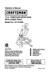
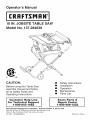
Operator's Manual
10 iN. JOBSITE TABLE SAW
Model No. 137.284630
C
US
CAUTION:
Before using this Table Saw,
read this manual and follow
all its Safety Rules and
Operating Instructions
Customer
Help Line
For Technical
Support
1-800-843-1682
®
®
®
®
®
Safety Instructions
Installation
Operation
Maintenance
Parts List
Sears Parts &
Repair Center
1-800-488-1222
Sears Brands Management Corporation
Hoffman Estates, IL 60179 USA
See the full line of Craftsman ® products at craftsman.corn
Click on the Craftsman Club_R_
link and join today!
Part No. 137284630001
Printed in China
SECTION
Warranty .............................................................................................................
Product Specifications ........................................................................................
Symbols ...............................................................................................................
Power Tool Safety ...............................................................................................
Table Saw Safety ................................................................................................
Electrical Requirements and Safety ....................................................................
Accessories and Attachments .............................................................................
Tools Needed for Assembly ................................................................................
Carton Contents ..................................................................................................
Know You r Table Saw .........................................................................................
Glossary of Terms ...............................................................................................
Assembly and Adjustments ..................................................................................
Operation ............................................................................................................
Maintenance .......................................................................................................
PAGE
2
3
4
5
8
11
13
13
14
16
17
19
33
42
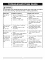
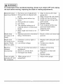
Troubleshooting Guide ........................................................................................
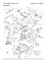
Parts List .............................................................................................................
44
47
Repair Protection Agreements ............................................................................
51
CRAFTSMAN
FULL
WARRANTY
If this Craftsman product fails due to a manufacturer's
defect in material or
workmanship with one year from the date of purchase, return it to any Sears store
Sears Parts & Repair Service Center, or other Craftsman outlet in the United
States for free repair (or replacement if repair proves impossible). This warranty
does not include expendable parts such as saw blades which can wear out from
normal use within the warranty period. This warranty applies for only 90 days from
the date of purchase if this product is ever used for commercial or rental purposes.
This warranty gives you special legal rights, and you may also have other rights
which vary from state to state.
Sears, Roebuck
and Co., Hoffman Estates,
IL 60179
,A WARNING
}
Some dust created by power sanding, sawing, grinding, drilling and other construction
activities contains chemicals known to the state of California to cause cancer, birth
defects or other reproductive harm. Some examples of these chemicals are:
®Lead from lead-based paints,
®Crystalline silica from bricks and cement and other masonry products, and
oArsenic and chromium from chemically4reated
lumber.
Your risk from these exposures varies, depending on how often you do this type of
work. To reduce your exposure to these chemicals: work in a well ventilated area, and
work with approved safety equipment, such as those dust masks that are specially
designed to filter out microscopic
particles. Avoid prolonged contact with dust from
power sanding, sawing, grinding,
drilling, and other construction
activities.
Wear
protective
clothing and wash exposed areas with soap and water. Allowing dust to
get into your mouth, eyes, or lay on the skin may promote absorption
of harmful
chemicals.
2 ............................................................................................
2010/03
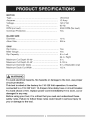
MOTOR
Type .............................................................................
Amperes .......................................................................
Voltage ........................................................................
Hz ................................................................................
Universal
15 Amp
120 V AC
60 Hz
RPM (no load) ............................................................
Overload Protection ....................................................
5000 RPM (No load)
Yes
BLADE SIZE
Diameter ......................................................................
Arbor Size ....................................................................
10 in.
5/8 in.
SAW
Rip Fence ......................................................................
Miter Gauge ..................................................................
Rip Capacity ................................................................
Maximum
Maximum
Maximum
Maximum
{_
Cut Depth @ 90° .........................................
Cut Depth @ 45 ° .........................................
Diameter Dado ............................................
Dado Cut Width ...........................................
Yes
Yes
8 in. Left
24 in. Right
3 in.
2-1/2 in.
6 in. (Stackable only)
1/2 in.
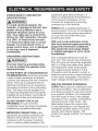
WARNING]
To avoid electrical hazards, fire hazards or damage to the tool, use proper
circuit protection.
This tool is wired at the factory for 110=120 Volt operation, it must be
connected to a 110=120 Volt / 15 Ampere time delay fuse or circuit breaker.
To avoid shock or fire, replace power cord immediately if it is worn, cut or
damaged in any way.
Before using your tool, it is critical that you read and understand these
safety rules. Failure to follow these rules could result in serious injury to
you or damage to the tool.
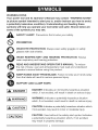
WARNING iCONS
Your power tool and its Operator's Manual may contain "WARNING iCONS"
(a picture symbol intended to alert you to, and/or instruct you how to avoid,
a potentially hazardous condition). Understanding
and heeding these
symbols will help you operate your tool better and safer. Shown below are
some of the symbols you may see.
A
SAFETY ALERT:
®
PROHiBiTiON
O
WEAR EYE PROTECTION: Always wear safety goggles or safety
glasses with side shields.
Precautions that involve your safety.
WEAR RESPIRATORY AND HEARING PROTECTION:
wear respiratory and hearing protection.
Always
READ AND UNDERSTAND OPERATOR'S MANUAL: To reduce
the risk of injury, user and all bystanders must read and understand
operator's manual before using this product.
KEEP HANDS AWAY FROM BLADE: Failure to keep your hands away
from the blade will result in serious personal injury.
SUPPORT AND CLAMP WORK
,A
i,_
DANGER
WARNING
I
DANGER: Indicates an imminently hazardous situation
which, if not avoided, will result in death or serious injury.
]
WARNING: Indicates a potentially hazardous situation
which, if not avoided, could result in death or serious injury.
Indicates a potentially hazardous situation which,
IA CAUTION]CAUTION:
if not avoided, may result in minor or moderate injury.
[ CAUTION
]
CAUTION: Used without the safety alert symbol indicates
a potentially hazardous situation which, if not avoided,
may result in property damage.
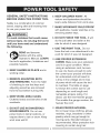
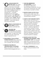
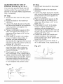
GENERALSAFETY
iNSTRUCTiONS
BEFORE USING THiS POWER TOOL
6. KEEP CHILDREN AWAY. All
visitors and bystanders should be
kept a safe distance from work area.
Safety is a combination of common
sense, staying alert and knowing how
to use your power tool.
,A WARNING
To avoid mistakes
7. MAKE WORKSHOP
with padlocks, master switches or by
removing starter keys.
I
8. DO NOT FORCE THE TOOL. It will
that could cause
do the job better and safer at the
rate for which it was designed.
serious injury, do not plug the tool in
until you have read and understood
the following.
.
CHILD PROOF
9. USE THE RIGHT TOOL. Do not
force the tool or an attachment to do
READ and become
familiar with the entire
a job for which it was not designed.
Operator's Manual. LEARN
the tool's application, limitations and
possible hazards.
10.USE PROPER EXTENSION
CORDS. Make sure your extension
cord is in good condition. When
using an extension cord, be sure
to use one heavy enough to carry
the current your product will draw.
An undersized cord will result in
2. KEEP GUARDS iN PLACE and in
working order.
3. REMOVE ADJUSTING KEYS
AND WRENCHES. Form the habit
a drop in line voltage and
of power which will cause
to overheat. The table on
12 shows the correct size
of checking to see that keys and
adjusting wrenches are removed
from the tool before turning ON.
in loss
the tool
page
to use
depending on cord length and
nameplate ampere rating. If in
doubt, use the next heavier gauge.
The smaller the gauge number, the
heavier the cord.
4. KEEP WORK AREA CLEAN.
Cluttered areas and benches invite
accidents.
11 .WEAR PROPER APPAREL.
5. DO NOT USE iN DANGEROUS
ENVIRONMENTS. Do not use
Do not wear loose clothing, gloves,
neckties, rings, bracelets or other
jewelry which may get caught in
moving parts. Nonslip footwear is
recommended. Wear protective hair
covering to contain long hair.
power tools in damp locations, or
expose them to rain or snow. Keep
work area well lit.
5
_,
12._
ALWAYS WEAR EYE
PROTECTION. Any power
tool could throw foreign
objects into the eyes and cause
U
permanent eye damage. ALWAYS
wear Safety Goggles (not glasses)
that comply with ANSI Safety
standard Z87.1. Everyday
eyeglasses have only impactresistant lenses. They ARE NOT
safety glasses. Safety Goggles are
available at Sears. NOTE: Glasses
or goggles not in compliance with
ANSI Z87.1 could cause serious
injurywhen they break.
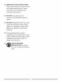
13.
WEAR A FACE MASK OR
DUST MASK. Sawing
operation produces dust.
14.
SECURE THE
WORKPIECE. Use clamps
or a vise to hold workpiece
when practical. It is safer than using
your hand and also it frees both
17.USE RECOMMENDED
ACCESSORIES. Consult
this Operator's Manual for
recommended accessories. The use
of improper accessories may cause
risk of injury to yourself or others.
18.NEVER STAND ON THE TOOL.
Serious injury could occur if the
tool is tipped or if the cutting tool is
unintentionally contacted.
19.CHECK FOR DAMAGED
PARTS.
Before further use of the tool, a
guard or other part that is damaged
should be carefully checked to
determine that it will operate
properly and perform its intended
function - check for alignment of
moving parts, binding of moving
parts, breakage of parts, mounting
and any other conditions that may
affect its operation. A guard or other
part that is damaged should be
properly repaired or replaced.
hands to operate the tool.
20.NEVER LEAVE THE TOOL
1&DISCONNECT
TOOLS FROM
POWER SOURCE before servicing,
and when changing accessories
such as blades, bits and cutters.
16.REDUCE THE RISK OF
UNINTENTIONAL STARTING.
Make sure switch is in the OFF
position before plugging the tool in.
RUNNING UNATTENDED. TURN
THE POWER "OFF". Do not walk
away from a running tool until the
blade complete stop and the tool is
unplugged from the power source.
21 .DO NOT OVERREACH. Keep
proper footing and balance at all
times.
22.MAINTAIN
TOOLS WITH CARE.
Keep tools sharp and clean for best
and safest performance. Follow
instructions for lubricating and
changing accessories.
23. DO NOT use power tool in
presence of flammable liquids or
gases.
24. DO NOT operate the tool if you are
under the influence of any drugs,
alcohol or medicationn that could
affect your ability to use the tool
properly.
25. Dust generated from certain
materials can be hazardous to your
health. Always operate saw in wellventilated area and provide for
proper dust removal.
26.
WEAR HEARING
PROTECTION to reduce
the risk of induced hearing
loss.
1.ALWAYSUSESAWBLADE
GUARD,rivingknifeandantikickbackpawlsfor every throughsawing operation. Through-sawing
operations are those in which the
blade cuts completely through
the workpiece when ripping or
crosscutting. Always be sure blade
guard is tightened securely.
2. ALWAYS HOLD WORKPIECE
FIRMLY against the miter gauge or
rip fence.
3. ALWAYS USE a push stick or
push block, especially when ripping
narrow stock. Refer to ripping
instructions in this Operator's Manual
where the push stick is covered in
detail. A pattern for making your own
push stick is included on page 46.
4. NEVER PERFORM ANY
OPERATION FREEHAND, which
means can using hands to support
the workpiece, but always use either
the fence OR the miter gauge to
position and guide the workpiece.
,&
DANGER
I
FREEHAND CUTTING iS THE
MAJOR CAUSE OF KICKBACK AND
FINGER/HAND AMPUTATIONS.
NEVER USE THE MITER GAUGE
AND FENCE SIMULTANEOUSLY.
5. NEVER STAND or have any part of
your body in line with the path of the
saw blade. Keep your hands out of
the saw blade path.
6. NEVER REACH behind or over the
cutting tool for any reason.
7. REMOVE the rip fence when
crosscutting.
8. DO NOT USE a molding head with
this saw.
9. FEED WORKPIECE iNTO THE
BLADE against the direction of
rotation only.
10.NEVER use the rip fence as a
cut-off gauge when crosscutting.
11 .NEVER ATTEMPT TO FREE A
STALLED SAW BLADE without
first turning the saw OFF. Turn
power switch OFF immediately to
prevent motor damage.
12.PROVIDE ADEQUATE SUPPORT
to the rear and the sides of the saw
table for long or wide workpieces.
1&AVOID KICKBACKS (work thrown
back towards you) by keeping the
blade sharp, the rip fence parallel
to the saw blade and by keeping
the riving knife, anti-kickback pawls
and guards in place, aligned and
functioning. Do not release work
before passing it completely beyond
the saw blade. Do not rip work that
is twisted, warped or does not have
a straight edge to guide it along the
fence. Do not attempt to reverse out
of a cut with the blade running.
14.AVOID
AWKWARD
OPERATIONS
and hand positions where a sudden
slip could cause your hand to move
into the saw blade.
15.NEVER USE SOLVENTS to
clean plastic parts. Solvents could
possibly dissolve or otherwise
damage the material. Only a soft
damp cloth should be used to clean
plastic parts.
16.MOUNT your table saw on a
bench or stand before performing
any cutting operations. Refer to
ASSEMBLY on page 19.
17"1,A_ WARNING
]
Never cut metals or masonry
products with this tool. This table
saw is designed for use on wood
and wood-like products only.
18.ALWAYS USE IN A WELL=
VENTILATED AREA. Remove
sawdust frequently. Clean out
sawdust from the interior of the saw
to prevent a potential fire hazard.
19.NEVER LEAVE THE SAW
RUNNING UNATTENDED. Do not
leave the saw until the blade comes
to a complete stop.
20.For proper operation follow the
instructions in this Instruction
Manual entitled ASSEMBLY AND
ADJUSTMENTS (Page 19). Failure
to provide sawdust fall-through and
removal hole will allow sawdust to
build up in the motor area resulting
in a fire hazard and potential motor
damage.
21 .USE ONLY saw blades
recommended with the warning that
the riving knife shall not be thicker
than the width of the groove cut by
the saw blade and not thinner than
the body of the saw blade.
22.USE PUSH-STICK OR PUSH
BLOCK to feed the workpiece past
the saw blade. The push-stick or
push block should always be stored
with the machine when not in use.
23.DIRECTION OF FEED. Feed
workpiece into a blade or cutter
against the direction of rotation of
the blade or cutter only.
SAW BLADE GUARD ASSEMBLY, ANTi=
KICKBACK ASSEMBLY AND RiViNG
KNIFE
Your table saw is equipped with a blade
guard assembly, anti-kickback assembly
and riving knife that covers the blade and
reduces the possibility of accidental blade
contact. The riving knife is a fiat plate that
fits into the cut made by the saw blade and
effectively fights kickback by lessening the
tendency of the blade to bind in the cut.
The blade guard assembly and antikickback assembly can only be used when
making through cuts that sever the wood.
When making rabbets and other cuts that
make non through cuts, the blade guard
assembly and anti-kickback assembly must
be removed and riving knife lowered to the
non through cut position marked on the
riving knife. Two anti-kickback pawls are
located on the sides of the riving knife
that allow the wood to pass through the
blade in the cutting direction but reduce
the possibility of the material being thrown
backwards toward the operator. Use all
components of the guarding system (blade
guard assembly, riving knife and antikickback assembly) for every operation
for which they can be used including all
through cutting. If you elect not to use
any of these components for a particular
application exercise additional caution
regarding control of the workpiece, the use
of push sticks, the position of your hands
relative to the blade, the use of safety
glasses, the means to avoid kickback
and all other warnings contained in this
manual and on the saw itself. Replace the
guarding systems as soon as you return
to thru-cutting operations. Keep the guard
assembly in working order.
KICKBACKS
KICKBACKS: Kickbacks can cause serious
injury. A kickback occurs when a part of the
workpiece binds between the saw blade
and the rip fence, or other fixed object, and
rises from the table and is thrown toward
the operator. Kickbacks can be avoided by
attention to the following conditions.
How to Avoid Them and Protect Yourself
from Possible Injury:
a. Be certain that the rip fence is parallel to
the saw blade.
b. Do not rip by applying the feed force to
the section of the workpiece that will
become the cut-off (free) piece. Feed
force when ripping should always be
applied between the saw blade and the
fence; use a push stick for narrow work,
6 in. (152 ram) wide or less.
c. Keep saw blade guard assembly, riving
knife and anti-kickback assembly in place
and operating properly. If anti-kickback
assembly is not operational, return your
unit to the nearest authorized service
center for repair. The riving knife must be
in alignment with the saw blade and the
anti-kickback assembly must stop a
kickback once it has started. Check their
action before ripping by pushing the wood
under the anti-kickback assembly. The
teeth must prevent the wood from being
pulled toward the front of the saw.
d. Plastic and composite (like hardboard)
materials may be cut on your saw.
However, since these are usually quite
hard and slippery, the anti-kickback pawls
may not stop a kickback. Therefore, be
especially attentive to following proper
set up and cutting procedures for ripping.
e. Use saw blade guard assembly, antikickback assembly and riving knife for
every operation for which it can be used,
including all through-sawing.
f. Push the workpiece past the saw blade
prior to release.
g. Never rip a workpiece that is twisted or
warped, or does not have a straight edge
to guide along the fence.
h. Never saw a large workpiece that cannot
be controlled.
i. Never use the fence as a guide or length
stop when crosscutting.
j. Never saw a workpiece with loose knots,
flaws, nails or other foreign objects.
k. Never rip a workpiece shorter than 10 in.
(254 mm).
I. NEVER use a dull blade - replace or
have resharpened.
m.NEVER use a rip fence and miter
gauge together.
n. Keep hands out of saw blade.
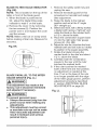
POWER SUPPLY AND MOTOR
SPECiFiCATiONS
i,A WARNING
]
To avoid electrical hazards, fire
hazards, or damage to the tool, use
proper circuit protection. Use a
seperate electrical circuit for your
tool. Your table saw is wired at the
factory for 120V operation. Connect
to a 120V, 15 Amp circuit and use
a 15 Amp time delay fuse or circuit
breaker. To avoid shock or fire, if
power cord is worn, cut, or damaged
in any way, have it replaced
immediately.
GROUNDING
i,_ WARNING
iNSTRUCTiONS
i
This tool must be grounded while
in use to protect the operator from
electrical shock.
iN THE EVENT OF A MALFUNCTION
OR BREAKDOWN, grounding provides
a path of least resistance for electric
currents and reduces the risk of electric
shock. This tool is equipped with an
electrical cord that has an equipmentgrounding conductor and a grounding
plug. The plug must be plugged into
a matching receptacle that is properly
installed and grounded in accordance
with all local codes and ordinances.
DO NOT MODIFY THE PLUG
PROVIDED. if it will not fit the
receptacle, have the proper receptacle
installed by a qualified electrician.
iMPROPER CONNECTION of the
equipment grounding conductor can
result in risk of electric shock. The
conductor with the green insulation
(with or without yellow stripes) is the
equipment grounding conductor. If
repair or replacement of the electrical
cord or plug is necessary, do not
connect the equipment grounding
conductor to a live terminal.
CHECK with a qualified electrician or
service person if you do not completely
understand the grounding instructions,
or if you are not certain the tool is
properly grounded.
USE only 3=wire extension cords
that have three=pronged grounding
plugs with three=pole receptacles
that accept the tool's plug. Repair
or replace damaged or worn cords
immediately.
Use a separate electrical circuit for
your tool. This circuit must not be less
than #14 wire and should be protected
with a 15 Amp time delay fuse. Before
connecting the motor to the power
line, make sure the switch is in the
off position and the electric current is
rated the same as the current stamped
on the motor nameplate. Running at a
lower voltage will damage the motor.
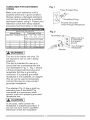
USE THE PROPER EXTENSION
CORD. Make sure your extension cord
is in good condition. Use an extension
cord heavy enough to carry the current
your product will draw. An undersized
cord will cause a drop in line voltage
resulting in loss of power, overheating
and burning out of the motor. The
table below shows the correct size
to use depending on cord length and
nameplate ampere rating. If in doubt,
use the next heavier gauge. The
smaller the gauge number, the heavier
the cord.
GUIDELINES
FOREXTENSION
CORDS
Makesureyourextension
cordis
Fig. 1
Three-Pronged
properly wired and in good condition.
Always replace a damaged extension
cord or have it repaired by a qualified
technician before using it. Protect your
extension cords from sharp objects,
excessive heat and damp or wet areas.
,
•
=
•
e==
AWG-
15.24
30.48
American
g Prong
Properly Grounded
Three-Pronged Receptacle
•
(When using 120 volts only)
Ampere Rating
Total length
of Cord
More Than Not More Than
25
50
100
150
(7.62
Plug
Fig. 2
ft.
45.72
Grounding Lug
/
/
_-',_
..<_L
m)
Wire Gauge
0
6
18
16
16
14
6
10
18
16
14
12
10
12
16
16
14
12
me_
I,k_. WARNING]
This tool is for indoor use only. Do
not expose to rain or use in damp
locations.
This tool is intended for use on a
circuit that has a receptacle like the
one illustrated in Fig. 1. Fig. 1 shows
a three-pronged electrical plug and
receptacle that has a grounding
conductor. If a properly grounded
receptacle is not available, an adapter
(Fig. 2) can be used to temporarily
connect this plug to a two-contact
grounded receptacle.
The adapter (Fig. 2) has a rigid lug
extending from it that MUST be
connected to a permanent earth
ground, such as a properly grounded
receptacle box.
la, CAUTION
]
In all cases, make certain the
receptacle is properly grounded. If
you are not sure, have a qualified
electrician check the receptacle.
r_
__
_J
__
Make sure this
k_! I is connected
_ 4:_ L to a known
_
IIground.
_
_''_
Two-Pronged
_
"---_ Receptacle
Adapter
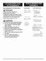
RECOMMENDED
ACCESSORIES
[,_
]
WARNING
SUPPLIED
Visit your Sears Hardware
Department or see the
Craftsman Power and Hand Tools
Catalog to purchase recommended
accessories for this power tool.
Blade wrench
308K DADO INSERT PLATE
Blade wrench
NOT SUPPLIED
Flat bladed
screwdriver
Phillips screwdriver
[!
[,_
WARNING
]
To avoid the risk of personal injury:
o Do not use adjustable (wobble)
type dadoes or carbide tipped
dado blades.
o Only use stackable dadoes.
o Maximum dado width is 1/2 in.
o Do not use a dado with a diameter
larger than 6 in.
o Do not use molding head set with
this saw.
o Do not modify this power
tool or use accessories not
recommended by Sears.
!!
!!
!!
!!
!!
]
Straight edge
4 mm hex
wrench
Adjustable wrench
and/or 8 mm, 10 mm,
13 mm, 14 mm,
17 mm wrench
Combination
square
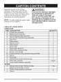
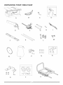
Separate all parts from packing
materials. Check each part with the
illustration on the next page and the
"Table of Loose Parts" to make certain
all items are accounted for, before
discarding any packing material.
NOTE: To make assembly easier, keep
contents of box together.
I,A
WARNING
]
if any part is missing or damaged,
do not attempt to assemble the
table saw, plug in the power
cord, or turn the switch ON until
the missing or damaged part is
obtained and is installed correctly.
Call 1=800-843-1682 for missing or
damaged parts.
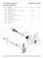
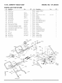
TABLE OF LOOSE PARTS
TABLE SAW
ITEM
A
B
C
D
E
F
G
H
I
J
K
L
M
N
O
P
Q
R
STAND
S
T
U
DESCRIPTION
Table saw assembly
Blade guard assembly
Anti-kickback pawls assembly
Riving knife hardware bag assembly
Rip fence
Miter gauge
Blade wrench
Hex wrench
Push stick
Rear table extension
Rear table extension tube
Power cord storage
Table extension wing hardware bag assembly
Blade
Dust bag
Handwheel handle hardware bag
Hex bolts, washers
Leg handle hardware assembly
Riving knife storage (locking handle)
Blade guard storage, screws
Roller wheel hardware assembly
Stand
QUANTITY
1
1
1
1
1
1
2
1
1
1
2
1
1
1
1
1
4 each
1
1 set
2
1
UNPACKING
YOUR TABLE
SAW
D
C
A
E
F
G
H
I
®
K
L
M
!!!!
p
Q
0
S
T
U
R
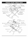
Miter gauge slot
Blade guard
fence
tilting
scale indicator
Miter gauge
Rip fence storage
table
locking lever
Miter gauge storage
lock lever
Overload reset
Blade bevel
lock handle
ON/OFF switch with
safety key
Blade elevation and
tilting handwheet
Blade
Table insert
Right extension table
Push stick
Riving knife
Anti-kickback
Rear table
extension wing
Power cord storage
Stand lock lever
)oft
Stand lock hook
Stand
pawls
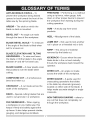
ANTI-KICKBACK
PAWLS - To
FREEHAND - Performing a cut without
using a rip fence, miter gauge, hold
down or other proper device to prevent
the workpiece from twisting during the
prevent the workpiece being kicked
upward or back toward the front of the
table saw by the spinning blade.
cutting operation.
ARBOR - The shaft on which the
blade or dado is mounted.
GUM - A sticky sap from wood
products.
BEVEL CUT - An angle cut made
through the face of the workpiece.
HEEL - Misalignment of the blade.
BLADE BEVEL SCALE - To measure
JAMB NUT - Nut used to lock another
if the angle of the blade is tilted when
set for a bevel cut.
nut in place on a threaded rod or bolt.
BLADE ELEVATION AND TiLTiNG
removed by the blade cut.
HANDWHEEL
KERF - The amount of material
- To raise and lower
KICKBACK-
the blade or tilt the blade to the angle
between 0° and 45 ° for bevel cuts.
Occurs when the saw
blade binds in the cut and violently
thrusts the workpiece back toward the
operator.
BLADE GUARD - A clear plastic cover
that positions over the blade while
cutting.
MITER CUT - An angle cut made
across the width of the workpiece.
COMPOUND CUT - A simultaneous
bevel and miter cut.
MITER GAUGE - A guide used for
crosscutting operations that slides
in the table top channels (grooves)
located on either side of the blade. It
CROSSCUT - A cut made across the
width of the workpiece.
helps make accurate straight or angle
crosscuts.
DADO - Special cutting blades that are
used to cut grooves in a workpiece.
NON-THROUGH
FEATHERBOARD
any cut that does not completely cut
through the workpiece.
- When ripping
a workpiece on your table saw, this
keeps it firmly and safely against the
rip fence. It also helps prevent chatter,
gouging, and dangerous kickback.
17
SAWING - refers to
OVERLOAD
RESET SWITCH -
Protects the motor if it overloads during
operation, provides a way to restart the
saw.
PUSH STICK- Used to push
workpieces when performing ripping
operations.
SAW BLADE PATH - The area of the
workpiece or table top directly in line
with the travel of the blade or the part
of the workpiece that will be cut.
SET - The distance between two saw
blade tips, bent outward in opposite
directions to each other. The further
apart the tips are, the greater the set.
PUSH BLOCK-
Used for ripping
operation when the workpiece is too
narrow to use a push stick. Always use
a push block for rip widths less than 2 in.
RESAWING - Flipping material to
make a cut the saw is not capable of
making in one pass.
i,A WARNING]
TABLE INSERT - Insert that is
removed from the table to install/
remove blades. It is also removed for
dado cutting. When dado cutting, a
dado insert plate must be used.
THROUGH SAWING - Making a cut
completely through the length or width
of a workpiece.
Resawing IS NOT recommended.
REVOLUTIONS PER MINUTE (RPM)
- The number of turns completed by a
spinning object in one minute.
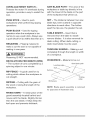
WORKPIECE
- Material
to be cut.
Saw blade path
Leadinc
Surface
RiP FENCE - A guide used for rip
cutting which allows the workpiece to
cut straight.
RiPPiNG - Cutting with the grain of
the wood or along the length of the
workpiece.
Trailing
edge
Workpiece
NOTE: Blade guard assembly
for purposes of illustration only.
RiViNG KNIFE - A metal piece of the
guard assembly located behind and
moves with the blade. Slightly thinner
than the saw blade, it helps keep the
kerf open and prevents kickback.
is removed
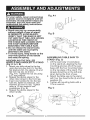
Fig. A=I
For your safety, never connect plug
to power source receptacle until all
assembly and adjustment steps are
complete, and you have read and
understood the safety instructions.
2
o Stand may pop up unexpectedly
without weight of saw on stand.
iN ORDER TO AVOID iNJURY,
VERIFY THAT THE BAND IS NOT
CUT AND THAT THE LOCK HOOKS
LOCATED IN THE FRONT OF
THE STAND ARE LOCKED ONTO
THE STOP SCREWS BEFORE
MOUNTING THE TABLE SAW.
o Do not release the stand hooks
until the table saw is properly
attached to the stand.
o To avoid injury, keep hands on the
over-mold portion of the handle
and away the spring.
Fig. B
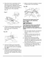
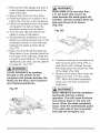
ASSEMBLING TABLE SAW TO
STAND (Fig. C)
1. Lift the saw body (1) and place
on the stand (2), aligning the four
mounting grooves (3) of the saw
base with the four mounting holes
on the top plate of the stand. The
wheels should be on the left side
when facing the front of saw.
2. Attach the table saw to the stand
with four hex head bolts (4) and four
washers (5).
3. Tighten all mounting bolts with a
13 mm wrench.
ASSEMBLING THE ROLLER
WHEELS AND HANDLES TO STAND
(Fig. A, A=I, B)
1. Attach one roller wheel to the leg
using the long hex bolt (1), the two
flat washers .(2), the sleeve (3) and
the lock nut (4), as shown.
(Fi.cj. A-l) Tighten the nut (4) using
a 1-7 mm wrench.
2. Repeat the above steps for the
other roller wheel to the front leg.
3. Insert one handle (5) into the leg
tube (6), fasten by bolts (7), two
washers (8) and nut (9). Ti.cjhten
using a 10 mm wrench and
screwdriver.(Fig. B)
.
.
4. Hepeat the above steps for the
other handle.
_
Fig. A
,'F,_
A-1
Fig. C
4
1_
J_
1
'1
Front
19
5
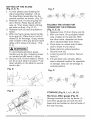
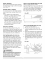
SETTING UP THE STAND
(Fig. D, E, F)
Fig. F
1. Cut the plastic band holding the
stand assembly together. Lift up
the Saw/Stand assembly into the
vertical position as shown. (Fig. D)
2. Release hook (1) securing leg set
(2) to frame. Raise leg set all the
way up. Then lower stand until leg
set rests on floor. (Fig. D, E)
3. Release hook (3) securing table to
frame.
4. With one hand, grasp stand handle
by its grip (4). Place foot in front of
wheel (5) for leverage. Grasp wheel
side of table at the grip (6) and raise
table until it snaps into place. (Fig.
D, F)
[,,_ WARNING
I
To avoid being pinched, grasp
handle only by grip. Grasping lower
on handle bar will result in injury.
5. Secure hook (7) from table to frame
pin (8) to lock table into place. Push
down slightly on the table to secure
hook to pin.
Fig. D
_i_
a-
:_
FOLDING THE STAND FOR
TRANSPORT OR STORAGE
(Fig. D, E, G)
1. Release hook (7) from frame pin (8).
2. With one hand, lift up slightly wheel
side of table on the grip (6). With
the other hand, depress lock lever
(9) to release table from frame.
3. Push down on wheel side of table
saw to lower it onto stand.
4. Raise stand to vertical position.
Secure hook (3).
5. Lower leg set (2) to frame. Secure
hook (1).
6. Tilt saw back onto wheels. Move
saw to desired location for operation
or storage. Saw can be storage in
vertical position.
Fig. G
2
i]
/
_9
.....
Fig. E
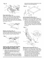
STORAGE (Fig. H, I, J, L, M, O)
4
spring
8
Rip fence, Miter gauge (Fig. H)
Storage brackets for the rip fence (1)
and miter gauge (2) are built into the
base and are located on the left side of
the saw housing.
b ) and the. locking.handle (6) to the
ottom ot the set plate (4).
Fig.N
Fig. K
Push stick (Fig. I, J)
Attach the metal push-stick storage
bracket (1) into the provided slots (2)
on the right side of the body shell.
The bracket will snap down into place.
Place the push stick (3) into the bracket
as shown in Fig. J.
Front
4
2
_._-_--5
c_-_...._6
1
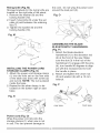
Anti-kickback
pawls (Fig. L)
Storage for the anti-kickback pawls (1)
is located on the right side of the stand.
1. Take the anti-kickback pawl (1) and
slide the red locking knob (2) up
and press the anti-kickback pawl
down to secure the entire assembly
on the storage. Release the locking
knob (2).
Fig. L
Blade wrenches (Fig. J)
Insert the two blade wrenches into the
slot (4) located on the right side of the
saw housing, under the push stick.
Fig. J
6
4
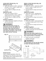
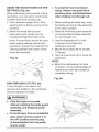
INSTALLING THE BLADE GUARD,
ANTI-KICKBACK PAWLS AND
RIVING KNIFE STORAGE (Fig. K)
1. Attach the retaining clip (1) to the
stand (2) using two screws .(3).
Tighten .screws securely using a
screwarwer.
2. Attach the set plate (4) to the stand
(2) using two screws (3) and tighten
screws securely. Thread the washer
Blade guard assembly (Fig. L)
Storage for the blade guard assembly
is located on the right side of the stand.
1. Take the blade guard assembly (5)
and slide the locking knob (6) up
and press the guard assembly
down so that the entire assembly
is located on the set plate (4).
Release the locking knob (6).
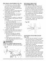
Rivingknife (Fig. M)
Storage brackets for the riving knife are
located on the right side of the stand.
1. Remove the washer (8) and the
locking handle (10).
2. Insert riving knife (9) under the set
plate (4) and between the retaining
clip (7).
3. Tighten the washer (8) and the
locking handle (10).
the cord. Do not wrap the power cord
around the dust port (3).
Fig. 0
1
Fig. M
3
2
9
1
ASSEMBLING THE BLADE
ELEVATION/TILT HANDWHEEL
(Fig. P)
1. Attach the blade elevation
handwheel (1) to the elevation rod
(2) at the front of the saw. Make
sure the slot (3) in the hub of the
handwheel (1) engage with the pins
(4), turn handle 90 degrees to align
pin with the recessed slot to hold
the handle in place.
2. Attach and tighten the crown nut
(5) and washer (6) with a 13 mm
wrench.
i/8
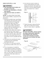
INSTALLING THE POWER CORD
STORAGE CLAMPS (Fig. N)
1. Attach the power cord storage clamp
(1) into the hole set on the rear side
of the table saw base with screw (2)
and nut (3). NOTE: The nut is placed
inside the base.
2. Repeat for the other clamp, to be
located on the bottom right on saw
base.
Fig. P
4
1
Fig. N
front view
Power cord (Fig. O)
Wrap the power cord (2) onto the
storage clamps (1) when saw is not
in use. This can prevent damage to
22
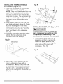
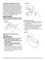
INSTALLING THE REAR TABLE
EXTENSION (Fig. Q, R)
1. Insert the two tubes (2) into the rear
table extension (1). (Fig. Q)
NOTE: They must be inserted into the
back of the extension with the bent
end last so that the bar will hold the
extension in place. The two openings
on the rear table (4) must line up with
the miter gauge slots on the main
table.
2. Snap plastic stops (3) over the two
rear table extension tubes (2). Make
sure the locating pin in the black
plastic stops fits into the matching
hole in the extension tube. This will
'lock' the tube into the extension.
(Fig. Q)
3. Insert the rear table extension tubes
(2) into the two extension tube
brackets under the table (5).
Fig. R
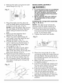
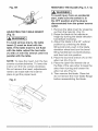
INSTALLING THE BLADE (Fig. S, T, U)
i_
To avoid injury from an accidental
start, make sure the switch is in the
OFF position and the plug is not
connected to the power source outlet.
.
Fig. Q
Bent End
/
\
\
4. Thread the screw (6) through the
hole in either side tube with a
screwdriver. NOTE: Only one side
is needed to have a screw inserted.
Tighten with a screwdriver, making
sure not to overtighten the screw (6).
(Fig. R)
WARNING]
Remove the table insert (1) by
snapping out from the hole (8).
Raise the blade arbor to the
maximum height by turning the
blade elevation handwheel
clockwise. (Fig. S)
Fig. S
2. Removethearbornut(2)andouter
bladeflange(3).(Fig.T)
RIVING KNIFE ASSEMBLY
l_
WARNING
l
e To avoid injury from an accidental
start, make sure the switch is in
the OFF position and the plug
is disconnected
from the power
source outlet.
e Never operate this saw without
the riving knife in the correct
position.
3. Placethebladeontothearbor(4)
withthebladeteethpointingforward
tothefrontofthesaw.(Fig.U)
NOTE:Leavetheplasticstriparound
thesawbladeatthistime.Remove
beforeusingthesawforthefirst
time.
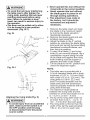
4. Makesurethebladefitsflush
againstthe innerflange.
5. Cleantheouterbladeflange(3)
andinstallit ontothearbor(4)and
againsttheblade.(Fig.T)
6. Threadthearbornut(2)ontothe
arbor,makingsuretheflatsideof
the nutis againsttheblade,then
hand-tighten.
(Fig.T)
7. Totightenthearbornut(2),place
theopen-endwrench(6)onthe
flatsofthesawarbor(5)tokeepthe
arborfromturning.(Fig.U)
8. Placethebox-endwrench(7)onthe
arbornut(2)andturnclockwise(to
the rearofthesawtable).(Fig.U)
9. Donotreplaceinsertuntilafterthe
nextstepofaddingtherivingknife
assembly.
>/
installing the riving knife assembly
(Fig. V, W, W=I)
NOTE: The table insert should be
removed and the blade raised to its
highest position before proceeding.
1. Loosen the blade lock handle (1).
Turn and move the handwheel (2)
to 45 ° on the bevel scale.
2. Tighten the bevel lock handle.
Fig. V
2
1
3. Place the riving knife (3) on the
mounting bracket (4) located behind
the saw blade. The two pins (5) on
the bracket should fit into the slot on
the riving knife.
4. Make sure the riving knife (3) is in
its highest position.
5. Insert the set plate (6) making sure
the two outer holes fit into the two
pins on the mounting bracket.
6. Insert the washer (7) into the lock
lever (8) and insert into the middle
hole the set plate and tighten.
7. Loosen the blade lock handle (1)
and return the blade to 0 ° and lock.
8. Place the table insert back into
position.
i_
WARNING
]
oTo avoid the lock lever interferring
the table insert, after tighten the
riving knife, position the lock lever
pointing downward before using
saw. Failure to maintain a level
insert can result in serious injury to
the operator.
oThe lever can be pulled out to allow
it to be turned to a new position
downward. (Fig. W-1)
Fig. W
J
Fig. W-1
Aligning the riving knife (Fig. X)
[_
WARNING]
o To avoid injury from an accidental
start, make sure the switch is in
the OFF position and the plug
is disconnected from the power
source outlet.
o Never operate this tool without the
riving knife in the correct position.
o Never operate this tool without
the blade guard in place for all
through sawing operations.
o This adjustment was made at
the factory, but it should be
rechecked and adjusted if
necessary.
1. Remove the table insert and raise
the blade to the maximum height
by turning the blade elevation
handwheel clockwise.
2. Remove the blade guard and antikickback pawl assembly.
3. Adjust the blade to the 0° vertical
position by unlocking the blade tilting
lock knob and turning the bevel tilting
handwheel counterclockwise, and
then lock into position.
4. To see if the blade (1) and riving
knife (2) are correctly aligned, lay a
combination square along the side
of the blade and against the riving
knife (making sure the square is
between the teeth of the blade).
5. Tilt the blade to the 45 ° position and
check the alignment again.
NOTE:
o This table saw is provided with a
10 inch diameter blade with a body
thickness of 0.07 in. (1.8 mm) thick
with a kerf of 0.10 in. (2.6 mm ).The
riving knife is 0.09 in. (2.2 mm)
thick.The blade diameter and the
blade body and kerf dimensions
must be properly matched with the
riving knife thickness.
o The maximum radial distance
between the riving knife and the
toothed rim of the saw blade is 0.12
in - 0.31 in. (3 mm - 8 mm)
o The tip of the riving knife shall not
be lower than 0.04 in. _ 0.2 in. (1
mm _ 5 mm) from the tooth peak.
o The riving knife is thinner than the
width of the kerf by approximately
1/64 in. (0.4 mm) on each side.
o Thebladebodymustbethinnerthan
thethicknessofthe rivingknifebut
thebladekerfmustbethickerthan
the rivingknife.
7. Checktherivingknifeandblade
alignmentagainatboth0° and45°.
8. Replace
thetableinsert,bladeguard
andanti-kickback
pawlassembly.
Fig. X
If the blade is partial to left side:
1. Turn the right adjustment screw (3)
counterclockwise and adjust the left
side adjustment screw (2) clockwise.
2. Remeasure, as described in steps 4
to 9 in the prior section.
3. When alignment is achieved, turn
the right adjustment screw (3) until it
touches the pivot rod (4).
Fig. Y
4
BLADE GUARD ASSEMBLY
I,A WARNING
i_
WARNING]
To avoid possible injury and damage
to the workpiece, be sure to INSTALL
THE BLADE WITH THE TEETH
POINTING TOWARD THE FRONT OF
TABLE in the direction of the rotation
arrow on the blade guard.
ADDITIONAL BLADE
ADJUSTMENTS (Fig. Y)
NOTE: The adjusting mechanism
is located above the blade height
adjusting hand wheel under the
tabletop. If the front and rear
measurements are not the same.
If the blade is partial to right side:
1. Turn the left adjustment screw (2)
counterclockwise and adjust the right
side adjustment screw (3) clockwise.
2. Remeasure, as described in steps 4
to 9 in the prior section.
3. When alignment is achieved, turn
the left adjustment screw (2) until it
touches the pivot rod (4).
l
To avoid injury from an accidental
start, make sure the switch is in
the OFF position and the plug is
disconnected from the power source
outlet.
o When installing the blade guard,
cover the blade teeth with a piece
of folded cardboard to protect
yourself from possible injury.
o Never operate this machine
without the blade guard in place
for all through sawing operations.
Installing the blade guard and
anti=kickback pawl assembly
(Fig. Z, AA, BB)
1. Make sure the blade is elevated to
its maximum height and the bevel is
set at 0 °. Make sure the bevel lock
handle is tight.
2. Take the anti-kickback pawl
assembly (1) and locate the red
sliding knob and push the locking
knob (2) up. (Fig. Z)
.
Place the front of assembly into the
back slot on the riving knife and
push downward. Release the locking
knob. Make sure the lock knob is
engaged in the hole and that there is
no movement of the assembly.
(Fig. Z)
7. Make sure that the assembly is locked
in place both in front and back.
Fig. BB
Fig. Z
5
4
Removing the blade guard and
anti-kickback
pawl assembly
(Fig. Z, BB)
I,,_ WARNING]
.
To avoid injury from an accidental
start, make sure the switch is in
the OFF position and the plug is
disconnected from the power source
outlet.
Take the blade guard assembly and
locate the red sliding locking knob
(3) on the back of assembly.
(Fig. AA)
Fig. AA
1. With the blade elevation handwheel
raise the blade to the maximum
height.
2. Loosen the blade lock handle and
then turn the handwheel to 45 ° on
the bevel scale.
3. Tighten the bevel lock handle.
4. Remove the anti-kickback pawl
assembly by pressing up on the red
knob (2) and lifting the assembly off
the riving knife. (Fig. Z)
5. Remove the blade guard assembly
by pressing up on the red knob
(3) and lifting the assembly off the
riving knife. (Fig. BB)
6
5. Insert the blade guard assembly
onto the riving knife so that the pin
(4) engages into slot (5) completely.
(Fig. BB)
6. Slide the red locking knob (3) up
and press the guard assembly down
so that the entire assembly is flat on
the riving knife. Release the locking
knob (3).
27
AVOIDING KICKBACKS (Fig. CC)
(Work thrown back towards you) by
keeping the blade sharp, the rip fence
parallel to the saw blade and by keeping
the riving knife, anti-kickback pawls and
guards in place, aligned and functioning.
Do not release work before passing it
completely beyond the saw blade. Do not
rip work that is twisted, warped or does
not have a straight edge to guide it along
the fence. Do not attempt to reverse out
of a cut with the blade running.
Fig. DD
i,A WARNING]
improper riving knife alignment can
cause "kickback" and serious injury.
Fig. CC
Anti= kickback pawl
RIP FENCE (Fig. EE)
1. Lift upward on the rip fence handle
(1) so the rear holding clamp (2) is
fully extended.
2. Place the rip fence on the saw table,
position the set plate (3) under the
front of fence and then lower the
back of fence onto the table.
3. Push down on the fence handle (1)
to lock.
Fig. EE
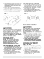
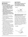
iNSTALLING
(Fig. DD)
THE DUST BAG
i,A WARNING]
o Do not use this saw to cut and/or
sand metals. The hot chips or
sparks may ignite sawdust or the
bag material.
o To prevent hazard, clean and
remove sawdust from under the
saw frequently.
1. Place the dust bag (1) around the
neck (3) of the dust port (2) and tie
the dust bag by pulling the string
tight and secure with the springloaded tie clip (4).
1
RiP FENCE ADJUSTMENT (Fig. FF)
1. The fence (1) is moved by lifting
up on the handle (2) and sliding
the fence to the desired location.
Pushing down on the handle locks
the fence in position.
2. Position the fence on the right side
of the table and along the edge
miter gauge groove.
3. Lock the fence handle. The fence
should be parallel with the miter
gauge groove.
4. If adjustment is needed to make the
fence parallel to the groove, do the
following:
o Loosen the two bolts (3) and lift
up on the handle (2).
o Hold the fence bracket (4) firmly
against the front of the saw table.
Move the fence until it is parallel
with the miter gauge groove.
o Push the handle down and
tighten both bolts.
5. If fence is loose when the handle is
in the locked (downward) position,
do the following:
o Move the handle (2) upward
and turn the adjusting nut (5)
clockwise until the rear clamp is
snug.
o Over-tightening the adjusting
bolts will cause the fence to come
out of alignment.
i,A WARNING]
Failure to properly align fence can
cause "kickback"
and serious
injury.
Fig. FF
1
2
RiP FENCE iNDiCATOR
ADJUSTMENT (Fig. GG)
1. The rip fence indicator (6) points to
the measurement scale. The scale
shows the distance from the side of
the fence to nearest side of the blade.
2. Measure the actual distance with a
rule. If there is a difference between
the measurement and the indicator,
adjust the indicator (6).
3. Loosen the screw (7) and slide the
indicator to the correct measurement
on the scale. Tighten the screw and
remeasure with the rule.
Fig. GG
ADJUSTING THE MITER GAUGE
(Fig. HH)
1. Loosen the lock handle (1) to allow
the miter body (2) to rotate freely.
Position the miter body at 90 ° so the
positive detent secures its position.
Tighten the lock handle to hold the
miter body in position.
2. If the pointer (3) requires adjustment,
loosen the screw under the pointer
with a screwdriver. Adjust the pointer
to 90 ° on the scale, then firmly
tighten the adjustment screw.
3. To change angles on the miter gauge,
loosen the lock handle (1) and rotate
the miter body to the desired angle
as indicated by the scale. Secure in
position by tightening the lock handle.
REMOVING THE BLADE (Fig. S, T, U)
I,,A WARNING]
To avoid injury from an accidental
start, make sure the switch is in
the OFF position and the plug is
disconnected from the power source
outlet.
ADJUSTING THE TABLE iNSERT
(Fig. ii)
[,A WARNING]
To avoid serious injury, the table
insert (2) must be level with the
table, if the table insert is not flush
with the table, adjust the two bolts
(1) with a 4 mm he× wrench until it is
parallel with the table.
NOTE: To raise the insert, turn the hex
screws counterclockwise. To lower the
insert, turn the hex screws clockwise.
Do not remove the insert, adjustments
need to be made with the insert in
place to get the proper level.
Fig. II
1. Remove the table insert by snapping
out from the hole (8). (Fig. S)
2. Raise the blade to the maximum
height by turning the blade elevation
handwheel clockwise.
3. Adjust the blade to the 90 ° vertical
position by unlocking the blade
tilting lock knob, push in the blade
elevation wheel and turn the bevel
tilting handwheel counterclockwise,
and then lock into position.
4. Place the box-end wrench (7) on the
arbor nut (2). (Fig. U)
5. Place the open-end wrench (6) on
the flats of the saw arbor to keep the
arbor from turning and loosen the
arbor nut (2). (Fig. U)
6. Then remove the blade. Clean but
do not remove the inner blade flange
before reassembling the blade.
ADJUSTING THE 90 ° AND 45 °
POSiTiVE STOPS (Fig. JJ, JJ=l)
Your saw has positive stops that will
quickly position the saw blade at 90 °
and 45 ° to the table. Make adjustments
only if necessary.
90 ° Stop
1. Disconnect the saw from the power
source.
2. Raise the blade to the maximum
elevation.
3. Loosen the blade bevel lock handle
and move the blade to the maximum
vertical position and tighten the
bevel lock handle.
4. Place a combination square on the
table and against the blade (1) to
determine if the blade is 90 ° to the
table. (Fig. Z)
5. If the blade is not 90 ° to the table,
loosen or tighten (depending on
whether you are increasing or
decreasing the degrees) the hex bolt
(3) with a 5 mm hex wrench until you
achieve 90 °. (Fig. Z-l)
6. Loosen the bevel lock handle and
reset the blade at the maximum
vertical position, then tighten the
bevel lock handle.
7. Check again to see if the blade is
90 ° to the table. If not, repeat step 5.
8. Lastly, check the bevel angle scale. If
the pointer does not read 90 °, loosen
the screw holding the pointer and
move the pointer so it is accurate at
0° and retighten the pointer screw.
Fig. JJ
45 ° Stop
1. Disconnect the saw from the power
source.
2. Raise the blade to the maximum
elevation.
3. Loosen the blade bevel lock handle
and move the blade to the maximum
bevel position (45°)and tighten the
bevel lock handle.
4. Place a combination square on the
table and against the blade (2) to
determine if the blade is 45 ° to the
table. (Fig. Z)
5. If the blade is not 45 ° to the table,
loosen or tighten (depending on
whether you are increasing or
decreasing the degrees) the hex bolt
(4) with a 5 mm hex wrench until you
achieve 45 °. (Fig. Z-l)
6. Loosen the bevel lock handle and
reset the blade at the maximum
bevel position (45°), then tighten the
bevel lock handle.
7. Check again to see if the blade is
45 ° to the table. If not, repeat step 5.
Fig. JJ-1
3
BLADETiLTiNG SCALE iNDiCATOR
(Fig. KK)
NOTE: This is located on the top of the
table, in front of the blade guard.
1. When the blade is positioned at
90 °, adjust the blade tilting scale
indicator to read 0 ° on the scale.
2. Remove the cover (1) by removing
the two screws (2). Position the
pointer over 0 ° and replace the cover
and the screws.
NOTE: Make a trial cut on scrap wood
before making critical cuts. Measure for
accuracy.
1. Remove the safety switch key and
unplug the saw.
2. Remove the blade guard for this
procedure but reinstall and realign
after adjustment.
3. Raise the blade to the highest
position and set at the 0° angle
(90 ° straight up).
4. Select and mark, with a felt tip marker,
a blade tooth having a "right set" and
rotate the blade so the marked tooth
is 1/2 in. above the table.
5. Place the combination square base
(1) into the right side miter gauge
groove (2). (Fig. BB)
6. Adjust the rule so it touches the front
marked tooth and lock ruler so it holds
its position in the square assembly.
7. Rotate the blade bringing the
marked tooth to the rear and about
1/2 in. above the blade.
8. Carefully slide the combination
square to the rear until the ruler
touches the marked tooth.
9. If the ruler touches the marked
tooth at the front and rear position,
no adjustment is needed at this
time. If not or the base of the rule
is no longer parallel with the edge
of the miter gauge groove, perform
adjustment procedure described
in section ADDITIONAL BLADE
ADJUSTMENTS on page 26.
Fig. KK
BLADE PARALLEL
TO THE MITER
GAUGE GROOVE (Fig. LL)
[_, WARNING]
This adjustment was made at the
factory, but it should be rechecked
and adjusted if necessary.
Fig. LL
[,A WARNING]
To prevent personal injury:
o Always disconnect plug from the
power source when making any
adjustments.
o This adjustment must be correct
or accurate cuts can not be made.
Also inaccurate adjustment can
result in kickback and serious
personal injury.
32
BASIC SAW OPERATIONS
RAISE THE BLADE (Fig. MM)
To raise or lower the blade, turn the
blade elevation handwheel (1) to the
desired blade height, and then tighten
the bevel lock handle (2) to maintain
the desired blade angle.
Fig. MM
1
2
2. To turn the saw OFF, move the
switch downward.
3. To lock the switch in the OFF position,
grasp the end (or yellow part) of the
safety switch key (1), and pull it out.
4. With the safety removal key
removed, the switch will not operate.
5. If the safety removal key is removed
while the saw is running, it can be
turned OFF but cannot be restarted
without inserting the switch key (1).
Fig. NN
TILTING THE BLADE
Two methods are available for tilting
the saw blade.
Rapid blade tilting:
Loosen the bevel lock handle (2), move
the handwheel (1) to the desired angle,
then tighten the bevel lock handle.
Fine adjustment blade tilting:
Loosen the bevel lock handle (2), push
in the handwheel (1) and at the same
time turn the handwheel (1) to tilt the
saw blade. When the saw blade is at
the desired angle, tighten the bevel
lock handle (2).
ON/OFF SWITCH (Fig. NN)
The ON / OFF switch has a safety
removal key. With the key removed from
the switch, unauthorized and hazardous
use by children and others is minimized.
1. To turn the saw ON, insert the safety
switch key (1) into the slot in the
switch (2). Move the switch upward
to the ON position.
OVERLOAD PROTECTION (Fig. NN)
This saw has an overload reset button
(3) that resets the motor after it shuts off
due to overloading or low voltage. If the
motor stops during operation, turn the
ON / OFF switch to the OFF position.
Wait about five minutes for the motor to
cool, the push the reset button (3) and
turn the switch to the ON position.
[_
WARNING]
To avoid injury, the ON / OFF switch
should be in the OFF position and
the plug removed from the power
source while the cool down takes
place, to prevent accidental starting
when the reset button is pushed.
Overheating may be caused by
misaligned parts or a dull blade or
undersized extensing cord. inspect
your saw for proper setup before
using it again.
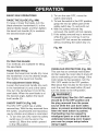
USING THE TABLE EXTENSION
(Fig. 00)
1. Release the extension cam locking
levers (3) in the front and rear table
positions.
2. Slide the extension (4) out until the
correct measurement is displayed
on the tube scale. The user sights
the scale off the edge of the table.
3. Tighten all extension cam locking
levers.
Fig. O0
I
WARNINGI
Before using the saw each time,
check the following:
1. The blade is tightened to the arbor.
2. The bevel angle lock knob is
tightened.
3. If ripping, make sure the fence
is locked into position and
is parallel to the miter gauge
groove.
4. The blade guard is in place and
working properly.
5. Safety glasses are worn.
The failure to adhere to these
common safety rules, and those
printed in the front of this manual,
can greatly increase the likelihood
of injury.
CUTTING OPERATIONS
There are two basic types of cuts:
ripping and crosscutting. Ripping is
cutting along the length and the grain of
the workpiece. Crosscutting is cutting
either across the width or across the
grain of the workpiece. (It is not safe to
rip or crosscut by freehand). Ripping
requires the use of the rip fence, and
crosscutting requires the miter gauge.
NEVER USE THE TWO AT THE
SAME TIME.
NOTE: Apply a coat of automobile wax
to the table. Wipe all parts thoroughly
with a clean dry cloth. This will reduce
friction when pushing the workpiece.
WARNING]
To prevent serious injury:
o Never use a miter gauge when
ripping.
o Never use more than one rip fence
during a single cut.
o Do not allow familiarity or frequent
use of your table saw to cause
careless mistakes. Remember
that even a careless fraction of
a second is enough to cause a
severe injury.
o Keep both hands away from the
blade and clear from the path of
the blade.
o The workpiece must have a
straight edge against the fence
and must not be warped, twisted,
or bowed when ripping.
1.Removethemitergaugeandstoreit
inthe"storage"
compartment
inthe
baseofthesaw.
2. Securetheripfencetothetable.
3. Raisethebladeso itis about1/8in.
higherthanthetopoftheworkpiece.
4. Placetheworkpiece
flatonthetable
andagainstthefence.Keepthe
workpiece
awayfromtheblade.
5.TurnthesawONandwaitforthe
bladetocometofullspeed.
6. Slowlyfeedtheworkpiece
intothe
bladebypushingforwardonlyonthe
workpiece
section(1)thatwillpass
betweenthebladeandthefence.
(Fig.PP)
7. Keepyourthumbsoffthetabletop.
Whenbothofyourthumbstouchthe
frontedgeofthetable(2),finishthe
cutwitha pushstick(3).Tomakean
additional
pushstick,usethepattern
onpage47. (Fig.PP)
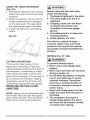
WARNING
I
AVOID KICKBACK by pushing
forward on the section of the
workpiece that passes between the
blade and the fence. Never perform
any freehand operations.
Fig. PP
WARNING]
When width or rip narrower than
2 in. the push stick cannot be
used because the blade guard will
interfere. Use the auxiliary fence (4)
and push block (5) as shown.
(Fig. QQ)
Fig. QQ
7
8. Continue pushing the workpiece (6)
with the push stick (3-Fig. PP) or
push block until it passes through
the blade guard and clears the rear
of the table. (Fig. QQ)
9. Never pull the piece back when the
blade is turning. Turn the switch
OFF. When the blade completely
stops, you can then remove the
workpiece.
l,_
6
WARNING
J
Never attempt to pull the workpiece
backwards during a cutting
operation. This will cause kickback
and serious injury to the user can
occur. When the blade completely
stops, raise the anti=kickback pawls
(7) on each side of the riving knife
and slide the workpiece out.
BEVELRIPPING
Thiscutis thesameas rippingexcept
thebladebevelangleis settoanangle
otherthan"0°''.
RIPPING SMALL PIECES
To avoid injury from the blade contact,
never make cuts narrower than 3/4 in.
wide.
1. It is unsafe to rip small pieces.
Instead, rip a larger piece to obtain
the size of the desired piece.
2. When a small width is to be ripped,
your hand cannot be safely put
between the blade and the rip fence,
use push stick or push block to pass
the workpiece completely through
and past the blade.
HELPFUL DEVICES
In order to make some of cuts, it is
necessary to use the devices like, push
block, featherboard and auxiliary fence,
which you can make yourself. Here are
some templates for your reference.
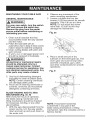
FEATHERBOARD (FIG. RR, SS)
A featherboard is a device used to
help control the workpiece by guiding
it securely against the table or fence.
Featherboards are especially useful
when ripping small workpieces and for
completing non-through cuts. The end
is angled with a number of short kerfs
to give a friction hold on the workpiece
and locked in place on the table
with C-clamps. Test that it can resist
kickback.
[_
WARNING
]
Place the featherboard against the
uncut portion of the workpiece to
avoid kickback that could cause
serious personal injury.
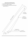
MAKE A FEATHERBOARD (Fig. RR)
Select a solid piece of lumber
approximately 3/4 in thick, 4 in wide and
18 in long. To make a featherboard, cut
one end of the lumber at 60 degrees,
then cut 8 in-long slots 1/4 in apart on
the angled end as shown in Fig. RR.
Fig. RR
_-I
,
_l
,
r £
I.
-'
18 in
"i
8in
-I
_l
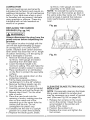
USE A FEATHERBOARD (Fig. SS)
1. Lower the saw blade (1).
2. Position the rip fence (2) to the
desired adjustment and lock the rip
fence.
3. Place the workpiece (3) against the
fence and over the saw blade area.
4. Adjust the featherboard (4) to resist
the workpiece forward of the blade.
5. Attached the C-clamps (5) to secure
the featherboard to the edge of the
table.
Fig. SS
5
\
AUXILIARY FENCE (Fig. TT)
Making the base:
o Start with a piece of 3/8 in. plywood
at least 5-1/2 in. wide or wider and
21 in. long or longer.
o Cut the piece to shape and size
shown:
Making the side:
o Start with a piece of 3/4 in.
hardwood at least 1-3/4 in. wide or
wider and 21 in. long or longer.
o Cut the piece to shape and size
shown:
Putting it together:
o Fasten the pieces together with glue
and woodscrews.
MAKE A PUSH BLOCK (Fig. UU)
Making the base:
o Start with a 3/8 in. plywood at least
5-1/2 in. wide or wider and 12 in.
long or longer.
o Cut the piece to shape and size as
shown.
Making the handle:
o Start with a 3/4 in. hardwood at
least 5 in. wide or wider and 7 in.
long or longer.
o Cut the piece to shape and size as
shown.
Making the bracket:
o Start with a 3/8 in. wood at least 3/8
in. wide or wider and 2-1/2 in. long
or longer.
o Cut the piece to shape and size as
shown.
Putting it together:
o Fasten the base and handle
together with glue and woodscrews.
i,,_ WARNING]
Make sure the screw heads do
not stick out from the bottom of
the base, they must be flush or
recessed. The bottom must be flat
and smooth enough to rest on the
saw table without rocking.
l,_
WARNING]
Make sure the screw heads do not
stick out from the bottom of the base,
they must be flush or recessed.
Fig. TT
_I
o Fasten the base and bracket
! 3/8 in. thick plywood base
together with glue.
!
l,_
WARNING
j
To avoid injury, do not use the screws
to fasten the base and bracket.
Fig. UU
m_
The edge must be
parallel with the face
PUSH BLOCK
Use for ripping operation when the
workpiece is too narrow to use a push
stick. Always use a push block for rip
widths less than 2 inches.
37
CROSSCUTTING
{_
(Fig. VV)
WARNING]
To prevent serious injury:
o Do not allow familiarity or frequent
use of your table saw to cause
careless mistakes. Remember
that even a careless fraction of
a second is enough to cause a
severe injury.
o Keep both hands away from the
blade and the path of the blade.
o Never attempt to pull the
workpiece backwards during a
cutting operation. This will cause
kickback and serious injury to the
user
can
occur.
1. Remove the rip fence and place
the miter gauge in the miter gauge
groove on the table.
2. Adjust the blade height so that it
is 1/8 in. higher than the top of the
workpiece.
3. Hold the workpiece firmly against
the miter gauge with the blade path
in line with the desired cut location.
Move the workpiece to a 1 in.
distance from the blade.
4. Start the saw and wait for the blade
(1) to come up to full speed. Never
stand directly in line of the saw blade
path, always stand to the side of the
blade that you are cutting on.
5. Keep the workpiece (2) against the
face of the miter gauge (3) and flat
against the table. Then slowly push
the workpiece through the blade.
6. Do not try to pull the workpiece back
with the blade turning. Turn the
switch OFF, and carefully slide the
workpiece out when the blade has
completely stopped.
I WARNING
i
Always position the larger surface
of the workpiece on the table
when crosscutting
and/or bevel
crosscutting
to avoid instability.
Fig. VV
USING THE WOOD FACING ON THE
MITER GAUGE (Fig. WW)
Slots are provided in the miter gauge
for attaching an auxiliary facing (1)
to make it easier to cut very long or
short pieces. Select a suitable piece of
smooth wood, drill two holes through
it and attach it to the miter gauge with
screws. Make sure the facing does not
interfere with the proper operation of
the saw blade guard. When cutting long
workpieces, you can make a simple
outfeed support by clamping a piece of
plywood to a sawhorse.
Fig. WW
/
/
BEVEL CROSSCUTTING (Fig. XX)
0°-45 ° BLADE BEVEL & 90 ° MITER
ANGLE This cutting operation is the
same as crosscutting except the blade
is at a bevel angle other than 0°.
[_
groove because the bevel angle may
cause the blade guard to interfere
with the cut if used on the left side
groove.
1. Set the miter gauge (3) to the
desired angle.
2. Place the miter gauge in the right
side groove of the table.
3. Set the blade (1) bevel to the
desired bevel angle and tighten the
blade bevel lock knob.
4. Hold workpiece (2) firmly against the
face of the miter gauge throughout
the cutting operation.
WARNING]
Always work to the right side of the
blade during this type of cut. The
miter gauge must be in the right side
groove because the bevel angle may
cause the blade guard to interfere
with the cut if used on the left side
groove.
1. Lower the blade to the down position.
2. Adjust the blade (1) to the desired
angle, and tighten the blade bevel
lock knob.
3. Tighten the miter lock handle (2) at
90 °"
4. Hold workpiece (3) firmly against the
face of the miter gauge throughout
the cutting operation.
Fig. XX
1
Fig. YY
2
MiTERiNG (Fig. ZZ)
00~45° MITER ANGLE
This sawing operation is the same as
crosscutting except the miter gauge is
locked at an angle other than 90 °.
1. Set the blade (1) to 0° bevel angle
and tighten the blade bevel lock knob.
2. Set the miter gauge (3) at the
desired miter angle and lock in
position by tightening the miter
gauge locking handle.
3. Hold the workpiece (2) firmly
against the face of the miter gauge
throughout the cutting operation.
3
2
/
/
/
COMPOUND MITER CROSSCUTTING
(Fig. YY) 00~45° BLADE BEVEL & 0 °
~45° MITER ANGLE
This sawing operation combines a
miter angle with a bevel angle.
[_
Fig. ZZ
3
WARNING]
Always work to the right side of the
blade during this type of cut. The
miter gauge must be in the right side
39
_
USING THE WOOD FACING ON THE
To avoid the risk of personal
injury. Always use push block,
RIP FENCE (Fig. as)
When performing some special cutting
operations, you can add a wood facing
to either side of the rip fence (2).
1. Use a smooth straight 3/4 in. thick
auxiliary fence and featherboard
when making non4hrough
cut.
1. Before starting the table saw, lower
wood board (1) that is as long as the
rip fence.
2. Attach the wood facing to the
the blade and riving knife assembly
to the down position.
2. Remove the blade guard assembly
fence with wood screws (3) (not
included) through the holes in the
fence. A wood fence should be used
and anti-kickback pawls assembly
for non-through cut.
3. Use the featherboard (1) with
when ripping material such as thin
paneling to prevent the material from
catching between the bottom of the
fence and the table.
C-clamps (3) to fasten the
workpiece securely.
4. Mount the auxiliary fence (4) with
C-clamps.
5. Use the push block (2) to move the
workpiece.
NOTE:
o Mount the featherboard to table
Fig. aa
as shown, so the leading edges of
featherboard will help workpiece
complete cutting.
Fig. bb
NON-THROUGH
(FIG.
A
non-through cut CUT
is used
to bb)
cut
grooves and rabbets in the workpiece
without exposed the blade.
i_ WARNING
....:
_
/
/
:'
".
Non-through
Cut
i
4
o Only this type cut is made
without installing the blade guard
assembly, anti-kickback
pawls
assembly.
o To avoid injury from an accidental
start, make sure the switch is in
the OFF position and the plug
is disconnected from the power
source outlet.
2
3
1
DADOCUTS(FIG.
cc, dd)
6. Use only the correct number of
round outside blades and inside
i,,_, WARNING]
chippers as shown in the dado set's
instruction manual. Blade/chippers
must not exceed 1/2 in. total in
width.
o Only Stackable dado blades can
be used on this saw.
o DO NOT use Adjustable or Wobble
type dadoes.
o The maximum
1/2 in.
Fig. cc
dado cut width is
-----4-----1
llitl
_H
anti-kickback pawl assembly, blade
guard assembly and riving knife
assembly for dado cuts ONLY.
Reinstall and realign blade guard
for all through-sawing operations.
Install a dado not exceeding 6 in. in
diameter and 1/2 in. in width
2. Install the dado table insert making
sure that the rear of the insert is
flush with the table. If the dado insert
is not flush with the table, adjust the
two bolts on the insert with a 4 mm
hex wrench until it is parallel with the
table.
3. Instructions for operating the dado
is packed with the separately
purchased dado set.
4. The arbor (1) on this saw restricts
the maximum width of the cut to 1/2
in.
5. It is not necessary to install the
outside flange (2) before threading
on the arbor nut (3) for the maximum
1/2 in. dado cuts. Make sure that the
arbor nut (3) is tight, and that at least
one thread of the arbor sticks out
past the nut.
-2
J
J
NOTE: An optional dado insert plate
(part number 308K) is required for this
procedure.
1. Remove the table insert, saw blade,
_N
"3
7. Check the saw to ensure that the
dado will not strike the housing,
insert, or motor when in operation.
i,A
WARNING]
For your own safety, always replace
the blade, blade guard assembly,
anti=kickback pawl assembly,
riving knife assembly and table
insert when you finished
operation.
Fig. dd
the dado
Dado cut
MAINTAINING YOUR TABLE SAW
Observe any movement of the
motor mounting mechanism.
3. Loosen or tighten the four hex
screws (1) by hex wrench for smooth
operation. Only 1/8 turn at a time.
NOTE: Do not adjust the screw
more than 1/2 turn as this may
damage the mechanism.
.
GENERAL MAINTENANCE
WARNING
i
For your own safety, turn the switch
OFF and remove the switch key.
Remove the plug from the power
source outlet before maintaining or
lubricating your saw.
Fig. ee
1. Clean out all sawdust that has
accumulated inside the saw cabinet
and the motor.
2. Polish the saw table with an
automotive wax to keep it clean and to
make it easier to slide the workpiece.
3. Clean cutting blades with pitch and
gum remover.
4. A worn, cut, or damaged power cord
should be replaced immediately.
[_
x.
_
"N_'_._
I
_
,
.
WARNING]
All electrical or mechanical repairs
should be attempted only by a
trained repair technician. Contact
customer service for assistance. Use
only identical replacement parts. Any
other parts may create a hazard.
_ _.
_-_-,_
_\
..............-.
_ _
......
_
,
Place a small amount of dry
lubricant on the bevel gear (2). The
worm gear (3) must be kept clean
and free of sawdust, gum, pitch,
and other contaminants for smooth
operations.
Fig. ff
5. Use liquid dishwashing detergent
and water to clean all plastic parts.
NOTE: Certain cleaning chemicals
can damage plastic parts.
6. Avoid use of cleaning chemicals or
solvents, ammonia and household
detergents containing ammonia.
BLADE RAISING AND TILTING
MECHANISM (Fig. ee, ff)
After every five hours of operation,
the blade raising mechanism and
tilting mechanism should be checked
for looseness, binding, or any other
abnormalities.
1. With the saw disconnected from the
power source, turn the saw upside
down and pull up and push down on
the motor unit.
NOTE: If excessive looseness
is observed in any part of the
blade raising mechanism or tilting
mechanism, take the complete unit to a
Service Center.
_2
LUBRiCATiON
All motor bearings are permanently
lubricated at the factory and require no
additional lubrication. On all mechanical
parts of your table saw where a pivot
or threaded rod are present, lubricate
using graphite or silicone. These dry
lubricants will not hold sawdust as
would oil or grease.
rip fence, miter gauge and stand
assembly to the table saw.
NOTE: To reinstall the same brushes,
first make sure the brushes go back in
the same sides they came out. This will
avoid a break-in period that reduces
motor performance and increases
wear.
Fig. gg
3
REPLACING THE CARBON
[_
WARNING]
Always disconnect the plug from the
power source before inspecting the
brushes.
The carbon brushes included with the
unit will last approximately 50 hours
of running time, or 10,000 ON/OFF
cycles. Replace both carbon brushes
when either has less than 1/4 in. length
of carbon remaining, or if the spring or
wire is damaged or burned.
1. Remove the blade guard, blade,
rip fence, miter gauge and stand
assembly from the table saw.
2. Lower the blade height to its
minimum setting. This will make the
brushes's location easier to access.
3. Place cardboard or an old blanket
on the floor to protect the saw table
surface.
4. Place the saw upside down on the
protective material.
5. Tilt the blade elevation/tilting
handwheel (1) to the 45 ° position.
6. Remove the black plastic cap (2)
from the side of the motor (3).
7. Carefully remove the spring-loaded
cap, and then pull out the brush (4).
8. Repeat step 6 and 7 for the other
side of motor.
9. Place the new brush into the
opening of motor, making sure the
ears on the metal end of the
assembly go in the same hole the
carbon part fits into. Do not
overtighten the plastic cap.
10.Carefully set the saw in a upright
position on a clean level surface.
11 .Replace the blade guard, blade,
Fig. hh
'\\
\
\
/
CLEAN THE BLADE TILTING SCALE
INDICATOR
NOTE: Occasionally cleaning the blade
tilting scale indicator to remove dust
may be necessary as a result of normal
use. (Also see Fig. KK on page 32)
1. Release two screws on the cover
set on the pointer. Clean the dust
accumulated in the pointer and
inside of the cover.
2. Position the pointer to 0 °.
3. Replace the cover and tighten the
two screws.
i,A WARNING
]
To avoid injury from accidental starting, always turn switch OFF and unplug
the tool before moving, replacing the blade or making adjustments.
PROBLEM
POSSIBLE CAUSES
CORRECTIVE ACTION
Saw will not
start.
1. Saw is not plugged in.
2. Fuse blown or circuit breaker
tripped.
3. Cord is damaged.
4. Debris in on/off switch
1. Plug in saw.
2. Replace fuse or reset circuit
breaker.
3. Replace power cord.
4. Remove switch from saw
and separate in half. Clean
any debris accumulated
within.
Does not make
accurate 45 °
and
1. Positive stop not adjusted
correctly.
2. Tilt angle pointer not set
accurately.
1. Check blade with square
and adjust positive stop.
2. Check blade with square
and adjust to zero.
90 ° rip cuts.
Material pinched 1. Rip fence not aligned with
blade when
blade.
ripping.
2. Warped wood, edge against
fence is not straight.
1. Check and adjust rip fence.
2. Select another piece of
wood.
Material binds
on riving knife.
1. Check and align riving knife
with blade.
Saw makes
unsatisfactory
cuts.
1. Riving knife not aligned
correctly with blade.
1. Dull blade.
2. Blade mounted backwards.
3. Gum or pitch on blade.
4. Incorrect blade for work being
done.
5. Gum or pitch on blade
causing erratic feed.
1. Replace blade.
2. Turn the blade around.
3. Remove blade and clean
with turpentine and coarse
steel wool.
4. Change the blade.
5. Clean table with turpentine
and steel wool.
1_ WARNING
]
To avoid injury from accidental starting, always turn switch OFF and unplug
the tool before moving,
replacing
the blade or making adjustments.
Material kicked 1. Rip fence out of adjustment.
back from blade. 2. Riving knife not aligned with
blade.
3. Feeding stock without rip
fence.
4. Riving knife not in place.
5. Dull blade.
6. The operator letting go of
material before it is past saw
blade.
7. Miter angle lock knob is not
tight.
Blade does
1. Sawdust and dirt in elevation/
not raise or tilt
tilting mechanisms.
freely.
1. Align rip fence with miter
gauge slot.
2. Align riving knife with blade.
3. Install and use rip fence.
4. Install and use riving knife.
(with guard)
5. Replace blade.
6. Push material all the way
past saw blade before
releasing work.
7. Tighten knob.
Blade does
1. Replace with adequate size
cord.
2. Contact your electric
company.
not come up to
speed. Reset
trips too easily.
Machine
vibrates
excessively.
Does not make
accurate 45 ° and
90 ° crosscuts.
1. Extension cord too light or
too long.
2. Low house voltage.
1. Brush or blow out loose dust
and dirt.
1. Saw not mounted securely to 1. Tighten all mounting
workbench.
hardware.
2. Bench on uneven floor.
2. Reposition on flat level
3. Damaged saw blade.
surface.
3. Replace blade.
1. Miter gauge out of
1. Adjust miter gauge.
adjustment.
PUSH STICK CONSTRUCTION
®
®
®
Use good quality plywood or solid wood
Use 1/2 in. or 3/4 in. material
Push stick MUST be thinner than the width of
material being cut
/
/
/
/
/
/
Drill Hole
For Hanging
Notch To
Prevent Hand
/
/
From Slipping
/
/
/
/
/
/
/
/
/
/
/
/
/
/
/
/
/
//90 °
20 ° - 3C
Cut Here To
--
Push 1/2 in. Wood
Cut Here To
Push 3/4 in. Wood
10 IN. JOBSITE TABLE SAW
MODEL NO. 137.284630
i WAR.I.Gi
When
servicing
use only CRAFTSMAN
replacement
parts,
Use of any
other
parts
many
create
a
HAZARD or cause product damage. Any attempt to repair or replace electrical parts on this Table
Saw may create a HAZARD unless repair is done by a qualified service technician, Repair service
is available at your nearest Sears Service Center,
PARTS LiST FOR TABLE SAW SCHEMATIC A
I.D.
Description
08VH
CORD
0901
BUSH
Size
QTY
CLAMP
090Q
PLUNGER
09JK
WRENCH
0AW8
SEGMENT
HOUSING
GEAR
HEX
PUSH
2E3K
CR
2ESW
COVER
2ESX
NEEDLE
NEEDLE
0B3R
WRENCH
0648
WARNING
0B9P
CLAMP
0BA1
COMPRESSION
0BA4
SPACER
2MLL
0BA9
SPACER
2NSC
0BAB
SHIM
LABEL
SPRING
NUT
RE
ROLLING
2ETL
BAG
2NT1
CR
ROUND
CR
UPPER
FLAT
WASHER
@6131
2RVW
RETAINING
0JB2
FLAT
WASHER
@162512
2RW6
SET PLATE
0JBA
FLAT
WASHER
@5162
0J5C
FLAT
WASHER
@]38_10
0J6K
FLAT
WASHER
@630
0J6T
FLAT
WASHER
3/163/4
0374
FLAT
WASHER
]/45/8
0372
FLAT
WASHER
]/45/8
0378
FLAT
WASHER
]/4"1/2
0J7E
FLAT
WASHER
5/16
0J8D
FLAT
WASHER
3/83/4
0JAE
EXTERNAL
0JAF
EXTERNAL
0JB2
WAVE
WASHER
0JB5
WAVE
WASHER
0JD
1
SPRING
0JPA
HEX
0JPJ
0JVY
0JZY
]/16
3/32
11/16
SET PLATE
2RVR
GUIDE
5/64
CLAMP
WORM
2TDL
FLAT
GUARD
2V3E
BLADE
GUARD(RIGHT)
GUARD(LEFT)
TOOTH
LOCK
WASHER
@5
2X6N
SWITCH
2YEY
BODY
2YEZ
BACK
2YF0
SPLITTER
2YF4
RETAINING
HD
BOLT
HEX
SOC
HEX
SOC
0KOX
HEX
HD
SCREW
0KOY
HEX
HD
SCREW
0K3H
CRRE
0K5B
CR
0K4T
CR
M6
HD
CAP
TRUSS
PAN
HD
RE
CO_}NT
RE
TRUSS
RE
TRUSS
BOLT
HD
SCREW
2YF7
FRONT
2YF8
BACK
UPPER
TUBE
2YFC
MITER
SCALE
ASS'Y
M610
M6
SCREW
16
10
20
M610
12
M610
12
2YFD
BELT
4
2YFN
RIGHT
2
2YFP
SUPPORT
RETAINING
DUST
M508
4
2YNQ
SCREW
M407
10
2
2YHT
LOCKING
M508
_2
4
2YHU
Dt }ST PLATE
10
8
2Y J0
SPACER
16 16
RE ROUND
WASHER
0K8C
CR
RECOUNT
HD
HD SCREW
TAPPING
SCREW
M418
HANDLE
CRRE
PAN
HD
TAPPING
SCREW
M4
2
2YJA
MOTOR
0KA6
CRRE
PAN
HD
TAPPING
SCREW
M5_12
10
4
2YKP
KICK
0KBB
CRRE
PAN
HD
TAPPING
SCREW
M5
16 16
2
2YLQ
ANGLE
0KBQ
CRRE
PAN
HD
TAPPING
SCREW
M5
16 10
2YNE
SPACER
0KC8
M4
16 16
3
2YS0
SET
2
2YS7
MITER
2
2YSG
CR
2
2YSN
HAND
1
2YTP
RIP FENCE
1
2YU2
BODY
2YU5
TABLE
2YV5
HEIGHT
CR
RE TRUSS
0KDR
CR
RE
PANHD
SCREW
M50810
0KDW
CR
RE
PAN
HD
SCREW
M6
0KF7
CR
RE
PAN
HD
SCREW
M407
0K J0
CAP
HD
SQ
NECK
BOLT
M6
10
SQ
NECK
BOLT
M6
10
35
M6
10
T=B
M8
12BT=125
0KJN
CAP
HD
0KMS
HEX
NUT
0KQJ
CROWN
0K©W
TAPPING
SCREW
N_}T
LOCK
NUT
0KQX
NUT
0KRQ
SERRATED
0KTK
HD
TOOTHED
HEXAGON
FLANGE
HUT
20
12
M508
16
TERMINAL
0KWU
LEAD
WIRE
5
2ZEJ
T=6
2
2ZWK
CR
M6 _1 0
T=6
302W
FLAT
0LSL
CIRCUIT
0LWC
ROCKER
0SZY
SLIDING
BREAKER
BASE
ASS'Y
0SZZ
SLIDING
BASE
ASS'Y
10K5
HEX
SOC
10LF
HEX
NUT
147D
HEX
HD
212M
LEAD
SWITCH
SWITCH
25AP
HEX
HD
2625
POWER
27BF
LOCATION
27JR
HEX
29Z5
BLADE
CAP
M5_08
BOLT
25
ASS'Y
HD
CAP
CORD
BOLT
M6 _10
25
CLAMP
SEAT
SOC
SET
ASS'Y
SCREW
M5_08
6
PAWL
BOX
GAUGE
ASS'Y
RE COUNT
HD
WHEEL
M5"08
55
ASS'Y
SHELL
REGULATING
BOLT
ASS'Y
PLATE
RE
PAN
HD
SCREW
M6q0
WASHER
el)6
308E
POWER
CABLE
1
308H
INSERT
1
308Q
OPERATOR'S
1
309H
WASHER
1
30AT
LABEL
30AU
SCALE
SCALE(RIGHT}
SCALE(RIGHT}
CAUTION
30B3
POP
1
30J3
LOCKING
2
30JR
HANDLE
2
30JU
WARNING
4
30NM
LABEL
STICKER
SPECIAL
WASHER
TAPPING
SCREW
MS"0
ASS'Y
MANUAL
30AW
1
PAN HD PLAN
#23
30AV
30B2
1
SCREW
ASS'Y
1
4
ASS'Y
ROD
RECESSED
8
M5_08
ASS'Y
BACK
CROSS
I 0T=4
ASS'Y
COVER
307Z
1
BOLT
M6
SOC
1
2
ASS'Y
WIRE
1
T=5
RELIEF
0KUW
3
10
M6
STRAIN
10
WING
COLLECTOR
0KA4
1
RIGHT
{RIGHT)
CLIP
SCREW
CR
TUBE
EXTENSION
2YG©
HD
CR
20
UPPER
HD
0K6Y
0K7G
WING
CLIP
12
WASHER
HD
ASS'Y
16
WASHER
& WASHER
BOX
EXTENSION
M610
AND
40
10
ASS'Y
M610
AND
SCREW
10
8
M4_07
BRACKET
BLADE
BLADE
HEX
MS"I2
WASHER
POINTER
2TUY
2V3F
16
SCREW
SCREW
ASSAY
COLLAR
2TDD
@4
M508
HD
SPACER
WASHER
BOLT
TAPPING
ASSAY
PLATE
LOCK
PIN
10
CLIP
ANCHOR
TOOTH
HD
M5'08
CLAMP
2TD0
2TLZ
1/16
SCREW
GEAR
0J4E
3/32
HD
BRACKET
2RVP
2T6E
16
TUBE
CLAMPER
WRENCH
2SJU
HD
BASE
RE COUNT
HEX
I
WASHER
RE TRUSS
SLIDING
ARBOR
1/16
M5'08
WHEEL
0J3P
4
WASHER
POINTER
0BAE
2SE0
AND
DUST
CUSHION
2RVM
COLLAR
SCREW
STICK
2ETB
2JHQ
QTY
Size
HD
2FH5
2RVJ
SET
Description
2CBS
0B2B
0BAC
POINTER
I,D.
2A48
HANDLE
LABEL
BOLT
ASS'Y
70
21
3
8
10
10 iN. JOBSITE TABLE SAW
MODEL NO= 137=284630
SCHEMATIC A
!
!
I
!
!
I
J
10 iN, JOBSITE TABLE SAW
MODEL NO. 137.284630
PARTS LiST FOR MOTOR
Size
i.D.
3089
Description
FIELD ASS'Y
OHX9
NEEDLE BEARING
OJXS
OKCN
H EX. SOC. SETSCREW
CR. RE. PAN HEAD TAPPING & WA3HERSCREW
QTy
1
1
MS_J.8-8
M5"12'-50
2
2
OKTK
STRAIN RELIEF
1
OQFE
BRUSH COVER
2
OQFF
CARBON
2
BRUSH ASS'Y
OQFG
BRUSH HOLDER A,SS'Y
145Y
2DW9
CR. RE. PAN HD. SCREW & WASHER
WAVE WASHER
2RPP
FLOW GUIDE
2RRD
CUTTER SHAFT ASS'Y
2RWS
CR. RE. COUNTER-SUN
2
M5_,8-55
4
1
1
1
HEAD SCREW
M5_3.8-10
2
2YE5
BRACKET
1
2YH8
2YK4
MOTOR COVER
ARMATURE ASS'Y
1
1
2YK7
LABEL
1
\
k
\
\
/2RPP
\
'\
/...OKCN_
fqFFz
_QFG_
2YH8
10 IN. JOBSITE TABLE SAW
MODEL NO. 137.284630
PARTS LiST FOR STAND
LD.
Size
Description
QTY
0lAD
V_NG
NUT
O1AE
LEVELING
OJ4E
FLAT W_SH ER
q)6'13-1
PAD
LD.
5iXe
Description
CABLETIE
QT_
1
2A2R
LOCKING
1
2CFW
RUBBER FOOT BUSH
l
4
2CRF
HOOK
2
l
OJ4R
FLAT WASHER
¢10"20-3
4
2LAL
BUSH
OJ4W
FLAT WASHER
€8.2" lB-1.5
12
2VE/_
CR.-RE. TRU&S BD. SCREW
4
OJ50
FLAT WASHER
_>6.3" 15-4
3
2XGE
SLEEVE
2
1
M6" 1 .CI-_
1
OJ5E
FLAT WASHER
2
2YFE
STIFFENER
OJSG
FLAT WASHER
4
2YFF
STIFFENER
OJBO
WAVE
3
2YG4
BRACKET
ASS'Y
OJP7
HEX, HD, BOLT
MIO"
2
2YG9
BOTTOM
BRACK_
A_;'Y
2
OJPS
HEX, HD, BOLT
MS* 1.25-45
6
2YGD
BOTTOM
BRACKET A_3'Y
1
OJPT
HEX. HD. BOLT
M8" 1.25-60
1
2YHF
BOTTOM
BRACKET
OJUH
HEX. SOC.
M6*l.O-10
2
2YHG
SLIDER
2
0K76
CR.-RE. TRUSS HD. SCREW
M6"1.0_45
2
2BHH
BUMPER
2
OKTF
CR. RE. ROUND
WASHER
M5"0._8
B
2YBK
COLLAR
OK7G
CR, RE. ROUND
',A/ASHER HD. SCREW
M5"O,G12
4
2YHL
HANDLE
BAR
OK7V
CR, RE. TRUSS HD. ROUND
M6"1£_14
3
2YHM
TORSION
SPRING
OKDX
CR, RE. PAN HD,,%CREW
M6'1,0-25
2
2YHP
GRAND
OKDZ
CR, RE, PAN HD, SCREW
M6*l,G35
2
2YHT
LOCKING
OKQX
NUT
M6*l,O
6
2YUJ
C OMP RES_SION SPRING
2
7
2Z2H
HOOK
1
WASHER
HD. CAP BOLT
NUT
BD. SCREW
NECK SCREW
1,5-105
BT&ND
LOCK
IOLF
HEX. NUT
M6* l.O T=4
,3
3U_B
WASHER
270N
NUT CHUCK
MlO'l,5
2
30BO
CAUTION
2BSR
HEX. HD. BOLT
MS* 1.25-55
4
39Bl
WARNING
28BU
FLOOR
1
30_
ROLLING
]OLF
T=B
T=B
1
1
1
2
2
OK©Y
PLATE
M8_1.25
T=6
1
1
1
HANDLE
HANDLE
ASSAY
2
1
1
LABEL
LABEL
WHEEL
1
1
2
Congratulations on makL#g a smaftpurchase.
Your new Craftsman _' product is designed and
manufactured for years of dependable operation. But like all products, it may require repair
from time to time. That's when having a Repair Protection Agreement can save you money and
aggravation.
Here's what the Repair Protection Agreement*
[]
[]
[]
[]
[]
includes:
Expert service by our 10,000 professional repair specialists
Unlimited service and no charge for parts and labor on all covered repairs
Product replacement up to $1500 if your covered product can't be fixed
Discount of 10% from regular price of service and related installed parts not covered by the
agreement; also, 10% off regular price of preventive maintenance check
Fast help by phone - we call it Rapid Resolution - phone support from a Sears representative.
Think of us as a "talking owner's manual."
Once you purchase the Repair Protection Agreement, a simple phone call is all that it takes for you
to schedule service. You can call anytime day or night, or schedule a service appointment online.
The Repair Protection Agreement is a risk-free purchase. If you cancel for any reason during the
product warranty period, we will provide a full refund. Or, a prorated refund anytime after
the product warranty period expires. Purchase your Rep air Protection Agreement today!
Some limitations and exclusions
call 1-800-827-6655.
apply. For prices and additional
information
in the U.S.A.
*Coverage in Canada varies on some items, For full details call Sears Canada at
1-800-361-6665.
Sears Installation Service
For Sears professional installation of home appliances, garage door openers, water heaters, and
other major home items, in the U.S.A. or Canada call 1-800-4-1VlY-HOME _.
Your Home
For expeR troubleshooting and home solutions advice:
www, managemyhome
corn
For repair -in your home - of all major brand appliance,
lawn and garden equipment, or heating and cooling systems,
no matter who made it, no matter who sold it!
For the replacement parts, accessories and
owner's manuals that you need to do-it-you_elf
For Sears professional installation of home appliances
and items like garage door openers and water heaters
1-800-4-MY-HOME
Call an_ime_
®
day or night (USA
(1_004694663)
and Canada)
......................................
OurHome:
ii
For repair of carry-in items like vacuums, lawn equipment,
and ele_ronics, cail an_ime for the location of your nearest
Sears Parts & Repair Service Center
1 oo488-1222
w_v sears,tom
1-8oo4694663
conodo
wv_vv.sears.ca
To purchase a protection agreement on a pr_u_
Para pedir _ic:io
i
de reparaci6n
a domiciiio y para ordenar piezas:
1_88SU'HOGARe
(1-888_784_6427)
AU Canada
serviced by Sears
pour service
en francis:
1_O0-LE-FOYER Mc
(l-a_ ;_o6,3;;
vc_v,,_ars_ca
....
'_/S_rs
_ds
LLC