1
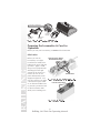
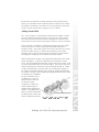
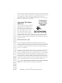
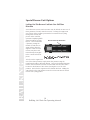
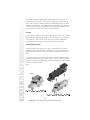
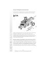
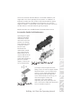
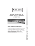
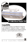
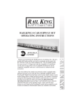
RAIL KING ® B y M T H E lectr ic T r ains SANTA FE STEEL RAIL FREIGHT HAULER 2-6-0 STEAM ENGINE TRAIN SET OPERATING INSTRUCTIONS Thank you for purchasing this RailKing Ready-to-Run Steam Engine Train Set. We at MTH Electric Trains take pride in manufacturing quality products like your set, and we hope that you will enjoy it for a long time. To ensure the maximum durability and pleasure from locomotive, rolling stock, track and transformer, please read all the way through the Quick Start Basic Operating Instructions you will find on pages 4. Remember that a little attention to routine maintenance yields a maximum of trouble-free performance. RAILKING Making the Most of Your Investment Table Of Contents QUICK START - BASIC OPERATION( Setting Up The RiteTrax® Track System Preparing The Locomotive & Cars For Operation Lubrication Operating The Locomotive & Cars Electronic Reverse Unit Transformer Operation Special Reverse Unit Options TRAIN SET MAINTENANCE Oil Grease Locomotive Lamp Replacement Passenger Car Lamp Replacement Locomotive Traction Tire Replacement RAILKING RITETRAX® TRACK LAYOUT PLANS TRANSFORMER COMPATIBILITY CHART EXPLODED PARTS VIEW DIAGRAM SAFTEY & WARNING PRECAUTIONS SERVICE AND WARRANTY INFORMATION HOW TO GET SERVICE LIMITED ONE YEAR WARRANTY 2 RailKing 2-6-0 Train Set Operating Manual 4 4 6 6 7 7 8 9 11 11 12 12 13 15 16 19 20 22 23 23 23 Compatibility Our designers have sized the engine to operate on any traditional 0-27 or larger O Gauge track system, including RiteTrax using any standard AC transformer including the Z-500 transformer packaged in your set. (See page 19 for a complete list of compatible transformers as well as wiring instructions.) All RailKing products are compatible with most other 3-rail locomotives, rolling stock, and accessories. Equipment Options Your ready-to-run set features a 2-6-0 steam locomotive equipped with an operating headlight, mechanical whistle, ProtoSmoke® operating smoke unit and a solid state electronic reverse unit. All are simple and fun to operate. In addition to the locomotive, your set should also include a circle of RiteTrax® track (8 curved sections), a RiteTrax® lighted lock-on and wire harness set (for connecting the track to the transformer) and a 50-watt Z-500 transformer and controller. CAUTION - ELECTRICALLY OPERATED PRODUCT: Not recommended for children under ten years of age without adult supervision. As with all electric products, precautions should be observed during handling and use to reduce the risk of electric shock. Transformer Ratings: Input: 120 VAC 60 HZ Only Output: 18VAC, 3A 54VA 3 RailKing 2-6-0 Train Set Operating Manual RAILKING You’ll find complete instructions for choosing and setting up options in the following pages. If you don’t read through the entire manual before starting to operate your equipment, be sure to check the Quick Start Basic Operating Instructions, which will give you the basics of the operating system. Quick Start Operating Instructions Track and Power Although MTH Electric Trains manufactures its own track and transformers, you can run your locomotive on 0-27 or wider-radius O gauge track wired to draw power from any of the standard compatible AC transformers listed in the chart on page 19. Be sure your track is in good condition—clean and securely connected—to keep the locomotive running and to prevent derailments. If you intend to utilize the RiteTrax® track sections included in the set, see the directions below. Setting Up the RiteTrax® Oval RAILKING Unlike other O Gauge track systems, each RiteTrax® track section features a realistic built-in roadbed base, solid nickel-silver track rails and realistic railroad ties all Align Quick Connect designed to give the owner Plugs and Gently Push RiteTrax® Sections Together an authentic looking track system. In addition, each RiteTrax® track section employs the use of quickconnect connectors instead of track pins or railjoiners to assemble the track sections to one another. The quick connectors and built-in base Figure 1: Preparing to snap RiteTrax® sections together by allow RiteTrax® track aligning Quick Connect Connectors together. sections to be setup anywhere, including some carpeted surfaces without the need for track nails or the worry of carpet stains. You can set up literally hundreds of different track designs utilizing RiteTrax® components. We’ve included just a few later in this manual for your reference. Each layout specifies the space required and the components needed to Figure 2: RiteTrax® sections in proper connected position. 4 RailKing 2-6-0 Train Set Operating Manual complete the track design. You can purchase additional track components from any authorized MTH reseller. Knock-out Must Be Removed Before Lighted Lockon Can Be Inserted Figure 3: Top view position of lighted lockon preparing to enter RiteTrax® section. transformer. Each RiteTrax® track section includes two “knock-out” tabs in the roadbed (on either end of the track) that must be removed The lighted lockon included in your set snaps into any RiteTrax® track section roadbed and functions as the interface between the track and the Remove Knock-out By Holding & Twisting With A Pair Of Pliers Figure 4: Underside view of RiteTrax® section with knock-out removed and lighted lockon in position for insertion. section with lighted lockon in fully seated position. Figure 6: Top view of RiteTrax® section with lighted lockon in fully seated position. 5 RailKing 2-6-0 Train Set Operating Manual RAILKING Figure 5: Underside view of RiteTrax® track to reveal the opening for the lighted lockon. To remove this knock-out grab the knock-out with a pair of pliers and gently twist the knock-out until it snaps away from the roadbed base. Once the knock-out has been removed, snap the lighted lockon into the roadbed taking care to make sure that the lockon arms snap into the roadbed electrical receptors. To complete the connection between the RiteTrax® track section and the transformer, simply plug in the color-coded wire harness that was included in your set. R E W O P ER LL RO RM FO -7 ER 5 NT CO FU PO LL WE R 0 IO T C E NE RL OT H IS H IR W B D L E B y R M le ILE AT H tr c K L ic N Gs in INT r a ® O F F TR S AN Also functions as a binding post. Red Harness Wire/Plug Red Harness Wire/Plug Black Harness Wire/Plug Black Harness Wire/Plug Figure 7: Wiring up the Z-500 transformer to the lighted lockon. Preparing the Locomotive & Cars For Operation Before you run your locomotive, you must oil the locomotive. Lubrication RAILKING Before you run the locomotive, use a light household or hobby oil to lubricate the gears and pick up rollers. Apply a small drop of oil (a pinpoint oiler will help place the right amount of oil where you need it) to each of the points indicated by in the diagram in figures 8. You may also want to use either a locomotive repair cradle or an old towel folded over to provide a protective bed for the locomotive shell while you’re working on it. Lubricate Pickup Rollers And Side Rod Linkage Grease Gears Figure 8: Lubrication points of RailKing 2-6-0 locomotive. Lubricate Pickup Rollers Figure 9: Lubricating The Tender. 6 RailKing 2-6-0 Train Set Operating Manual Because the locomotives’s internal gearing has been greased at the factory, you shouldn’t need to add more grease until you have run the locomotive for 50 hours or owned it for a year, whichever comes first. See the section on lubrication, pages(s) 11-12, for detail. Adding Smoke Fluid The 2--6--0 contains a self--powered smoke unit that outputs a steady stream of smoke through the smoke stack on the roof of the engine. The ON/OFF switch located next to the trailing truck must be in the ON position in order for the smoke unit to function. See Fig. 10 below. The smoke unit is essentially a small heating element and wick which soaks up and then “cooks" a mineral oil--based fluid that omits a harmless smoke. The smoke is then forced out of the stack via a small electric fan which runs at a constant speed. However, the smoke intensity can be varied by increasing the transformer voltage setting. The higher the setting, the more intense the smoke output Figure 10: Locating the ProtoSmoke® ON/OFF Switch 7 RailKing 2-6-0 Train Set Operating Manual RAILKING Before operating the engine, you should add smoke fluid to the smoke unit by pouring 15 - 25 drops of fluid into the locomotive’s smoke stack. Use the included ProtoSmoke™ smoke fluid vial or Seuthe, LGB or LVTS smoke fluid before you run the engine. If you don’t choose to add the fluid, then the smoke unit switch should be turned off. Failure to either add the fluid or turn the switch off could lead to damage to the smoke unit heating element and or wicking. Add the fluid through the smoke stack hole. After adding the fluid, gently blow into the stack to eliminate any air bubbles. Do not overfill the unit as overfilling can cause the fluid to leak out and coat the interior engine components. When the smoke output begins to diminish while running the engine, an additional 10--15 drops of smoke fluid should ProtoSmoke® ON/OFF Switch be added or the smoke unit switch should be turned off. When storing the engine for long periods of time, you may want to add at least 15 drops of fluid to keep the wick soaked with fluid and prevent it from drying out. After removing the engine from storage, it is advisable to add another 25 drops of fluid, letting the wick soak up the fluid for 15 minutes prior to operation. Operating The Engine and Cars Pushing Down On The Coupler Armature Opens The Coupler Knuckle Once the track has been assembled and the transformer wired to the track lock-on, you are almost ready to begin running your new train set. Place the engine and cars on the Figure 11: Pushing down on the coupler armature to open up the coupler knuckle. track and couple each up to one another. If the coupler is already closed, pressing down on the coupler armature will open the coupler knuckle to allow the couplers to interlock with one another. Before turning on the transformer, it is important to understand the features of your new train set. RAILKING Electronic Reverse Unit The 2--6--0 model is controlled by an electronic reverse unit. The reverse unit operates in the same manner that all reverse units function by using forward, neutral and reverse states that are entered each time the throttle is turned on and off or by using the transformer direction switch (if so equipped). In addition to the electronic reverse unit, your new train set locomotive features a mechanical whistle that can be activated by pressing the white Horn/Whistle button on your Z-500 transformer. Any compatible transformer whistle or horn button will also activate the horn in your new locomotive. Simply pressing the Horn/Whistle button whenever the throttle is above the OFF setting should activate the whistle. If the whistle doesn’t blow, increase the throttle setting and press the button again. The whistle will blow as long as the button is depressed. Now, if you’ve lubricated the locomotive friction points as indicated earlier, you’re almost ready to start running your train set. 8 RailKing 2-6-0 Train Set Operating Manual Transformer Operation The Z-500 provides the model railroad enthusiast with an easy to use, safe power source for AC-powered trains and accessories. Set up is quick and easy by following the setup diagram below. Functions: -5 0 0 RAIL KING ® T R ANS FOR MER CONT R OL L ER B y M T H E lectr ic T r ains BELL H OR N W HIS T L E OF F D I R E CT I ON LL FU E R W PO Bell: Press to activate a digital sound system bell (not found on NYC 2-6-0 Steam Engine Set model number 68505340227), press again to deactivate. P OW E R Figure 12: Z-500 Controls Horn/Whistle: Press to activate. Direction: Press to stop motion of train and press again to change direction Starting to Roll An alternative method to using the throttle to enter the next reverse unit phase is to press the direction button. When depressed, the transformer interrupts all power to the track as long as the button is depressed. Releasing the button reapplies power to the track at whatever voltage level the transformer throttle is set at. Press the horn button, the horn should sound. Note: Pressing the bell button will have no affect on your engine because your locomotive is not equipped with a bell. Only locomotives equipped with full digital sound systems (which feature engine sounds, horns, bells, air-release sound effects, squeaking brakes and many other locomotive related sound effects) can utilize the bell button. 9 RailKing 2-6-0 Train Set Operating Manual RAILKING Advanced the transformer throttle. The locomotive's light will come on but the engine will not move until you turn the throttle back OFF and then ON again. The engine should now proceed in the forward direction. At this point, advancing the throttle further will allow the engine to pick up speed, reducing the throttle will slow the engine down. Turning the throttle OFF and then back ON will park the engine into neutral. Cycling the throttle OFF and then back ON again one more time will allow the locomotive to enter reverse. Special Reverse Unit Options Locking Out The Reverse Unit Into One Full-Time Direction Your electronic reverse unit locomotive may be locked out into one of three positions; forward, neutral or reverse. Locking the engine into one of these three positions prevents the locomotive from cycling through the reverse unit phases and is useful for operators employing block signal operations on their Reverse Unit Lock-Out Switch layout. Once locked into a position, turning the throttle off and then on again will not allow the engine to enter the next reverse unit phase and instead keeps the engine in the current locked out Figure 13: Electronic Reverse Unit Lock-out Switch location phase. RAILKING (bottom chassis view). To lock out the engine into one of the three positions, simply enter that position using the transformer throttle or direction button. Once in the desired direction, remove the locomotive from the track and slide the ON/OFF switch located on the bottom of the chassis (See Figure 13) to the OFF position. This locks the engine into the desired direction. Sliding the switch back to the ON position resets the reverse unit into its normal reverse unit cycling phases. 10 RailKing 2-6-0 Train Set Operating Manual Using the Z-500 With Self-Recharging, Battery Equipped After-Market Sound Systems When using the Z-500 transformer with after-market digital sound systems employing a self-recharging battery backup system, operators should be aware MTH does not recommend leaving the engine in neutral with the power on and the throttle above the setting shown in Figure 10 for an extended period of time. If you are recharging the battery found in these after-market sound systems with a Z-500 transformer while in the neutral position, MTH recommends the throttle be positioned as shown in Figure 10 for optimum charging power. Train Set Maintenance Instructions Proper locomotive performance requires regular attention to lubrication. The following guidelines should be followed to ensure that your set’s locomotive last for many years. Oil Before operating the locomotive, apply a small drop of oil to lubricate the side rods and pick up rollers. Use light household oil and apply Grease Gears Figure 14: Removing the 2-6-0 locomotive shell from the chassis. sparingly only to the points indicated by Figure 14. Wipe away any excess, especially if oil spills onto the finish of the locomotive. To prevent accidental scratches or other damage to the locomotive shell while you are working, you may want to place the locomotive in a repair cradle or an old towel or other cloth folded to provide a firm but soft resting place. 11 RailKing 2-6-0 Train Set Operating Manual RAILKING Lubricate Pickup Rollers And Side Rod Linkage Check the locomotive oiling points periodically to be sure they are moving freely and quietly. If they are not, apply small amount of oil again. Also check locomotive wheels for dirt build up that can cause performance problems. Such dirt build up can interfere with electrical contacts, reduce traction (especially on elevated track sections), and cause neprene traction tires to wear out prematurely. Grease Grease may be added to the external drive gears in lieu of oil. To add grease simply apply liberally using a small screwdriver or toothpick to the gear teeth. Take care to rotate the gear by gently spinning the locomotive drive wheels so that all gear teeth can be greased. Lamp Replacement RAILKING Your locomotive and caboose car may occasionally burn out their headlights and/or interior lights. Should this occur, you will need to remove the body from the chassis in order to replace the burned out bulb. To remove the 2-6-0 locomotive cab from its chassis, follow the body removal instructions on the previous pages. Once the body has been removed, rotate the headlight bulb counter-clockwise as seen in Figure to remove the burned out bulb. Figure 16: Locating and removing the light bulb. Figure 17: Removing the boiler to change the light bulb. 12 RailKing 2-6-0 Train Set Operating Manual To remove the caboose car body from its chassis, turn the car over and locate and remove the four mounting screws (one in each corner of the car as seen in Figure 17) attaching the body to the chassis. Once the screws are removed, gently lift the car body up and away from the chassis. After removing the body from the chassis, turn the chassis over and locate the two car interior lamp housings mounted on the inside of the chassis. Remove the burned out bulb by pushing the bulb downward and rotating it counter-clockwise as seen in Figure 18. Once the bulb has been removed, insert the replacement bulb by pushing down and turning the bulb clockwise to lock into place. interior bulbs. Figure 17: Removing the caboose body from its chassis.. 13 RailKing 2-6-0 Train Set Operating Manual RAILKING Figure 18: Locating and removing the Traction Tire Replacement Instructions Your locomotive is equipped with two neoprene rubber traction tires (located on the rear drive wheels). While these tires are extremely Figures 19: Changing the locomotive traction RAILKING tires. durable and long-lasting there may arise a time where they will need to be replaced. Should this occur, you will need to remove the locomotive side rods (the rods that connect each drive wheel to one another) in order to slip the new tire over the grooved drive wheel. The side rods are fastened to the drive wheels with a screw that can be removed with a 5mm nutdriver. Before the new tire can be installed, you must make sure the old tire has been completely removed from the groove in the drive wheel. Use a razor blade or small flatblade screwdriver pry away any remains left from the old tire that may still be in the drive wheel groove. Once the old tire has been completely removed, slip the new tire onto the wheel. You may find it useful to use two small flatblade screwdrivers to assist you in stretching the tire over the wheel. Be careful to avoid twisting the tire when stretching it over the wheel. If a twist occurs, the tire will 14 RailKing 2-6-0 Train Set Operating Manual have to be removed and reinstalled or a noticeable wobble in your engine will occur when operating the locomotive. In addition, it is important to make sure that the tire is fully seated inside the groove. Any portion of the tire extending out of the groove can cause the engine to wobble. A razor blade can be used to trim away any excess tire that doesn't t seat itself inside the groove properly. Replacement tires are available directly from MTH Electric Trains. Locomotive Smoke Unit Maintenance Figure 20: Removing the locomotive body for smoke unit maintenance. Figure 21: Opening the smoke unit for wick replacement. you inspect and/or replace the wick taking care to not run the engine without fluid in the future. You can inspect the wick to see if it needs replacement by removing the smoke unit inspection cover from the body as seen in Fig. 21. After removing the chassis and inspection cover screws lift the inspection plate away and inspect the wick. If the wick is darkly discolored and hard, it should be replaced. 15 RailKing 2-6-0 Train Set Operating Manual RAILKING Operating the engine without smoke fluid and with the smoke unit switch in the ON position can damage your smoke unit wick, causing the wick to become hard, blackened and unabsorbant around the heating element. When this occurs, it may be difficult for the wick to soak up the smoke fluid resulting in poor or no smoke output. If that occurs, we recommend that RiteTrax® Layout Plans RAILKING The following track plans are just some of the many different track plans you can utilize when designing your model railroad. Each track plan contains a table indicating which track components and how many you will need to purchase. Some track plans may require additional transformer power to accommodate the current draws of the various accessories featured in the layout, including switches and lights. Track List: (6) 10“ Straight (10) O-31 Curved (4) O-31 Right Hand Switch (2) O-31 Left Hand Switch (4) 5.5“ Straight (10) 4.25“ Straight (4) 3.5“ Straight Item # (40-1001) (40-1002) (40-1004) (40-1005) (40-1012) (40-1017) (40-1018) Track List: (22) 10“ Straight (21) O-31 Curved (2) O-31 Right Hand Switch (1) O-31 Left Hand Switch (1) 90 Degree Crossing (2) 5.0“ Straight (1) 4.25“ Straight (2) 3.5“ Straight Item # (40-1001) (40-1002) (40-1004) (40-1005) (40-1006) (40-1016) (40-1017) (40-1018) Approximate Layout Size: 102“ x 32” (2.6m x 0.8m) Approximate Layout Size: 96“ x 60” (2.4m x 1.5m) 16 RailKing 2-6-0 Train Set Operating Manual Track List: (10) 10“ Straight (8) O-31 Curved (3) O-31 Right Hand Switch (1) O-31 Left Hand Switch (3) 5.5“ Straight (1) 5.0“ Straight (2) 4.25“ Straight (4) 3.5“ Straight Track List: (3) 10“ Straight (12) O-31 Curved (2) O-31 Right Hand Switch (2) O-31 Left Hand Switch (3) 5.5“ Straight (2) 5.0“ Straight (5) 3.5“ Straight (2) O-31 Half-Curved Item # (40-1001) (40-1002) (40-1004) (40-1005) (40-1012) (40-1016) (40-1018) (40-1022) Item # (40-1001) (40-1002) (40-1004) (40-1005) (40-1012) (40-1016) Approximate Layout Size: 84“ x 42” (2.1m x 1.1m) Approximate Layout Size: 92“ x 42” (2.3m x 1.1m) Approximate Layout Size: 96“ x 48” (2.4m x 1.2m) 17 RailKing 2-6-0 Train Set Operating Manual RAILKING Track List: (10) 10“ Straight (12) O-31 Curved (2) O-31 Right Hand Switch (2) O-31 Left Hand Switch (2) 5.5“ Straight (2) 5.0“ Straight Item # (40-1001) (40-1002) (40-1004) (40-1005) (40-1012) (40-1016) (40-1017) (40-1018) RAILKING Track List: (8) 10“ Straight (8) O-31 Curved (2) O-31 Right Hand Switch (2) O-31 Left Hand Switch (1) 90 Degree Crossing (4) 5.5“ Straight (2) 5.0“ Straight (2) 4.25“ Straight Item # (40-1001) (40-1002) (40-1004) (40-1005) (40-1006) (40-1012) (40-1016) (40-1017) Track List: (9) 10“ Straight (13) O-31 Curved (2) O-31 Right Hand Switch (1) O-31 Left Hand Switch (2) 5.5“ Straight (4) 5.0“ Straight (2) 4.25“ Straight (10) O-31 Half Curved (10) 3.5“ Straight Item # (40-1001) (40-1002) (40-1004) (40-1005) (40-1012) (40-1016) (40-1017) (40-1022) (40-1018) Track List: (22) 10“ Straight (10) O-31 Curved (3) O-31 Right Hand Switch (1) O-31 Left Hand Switch (2) 5.5“ Straight (2) 3.5“ Straight Item # (40-1001) (40-1002) (40-1004) (40-1005) (40-1012) (40-1018) Approximate Layout Size: 92“ x 36” (2.3m x 0.9m) Approximate Layout Size: 90“ x 48” (2.3m x 1.2m) Approximate Layout Size: 96“ x 48” (2.4m x 1.2m) 18 RailKing 2-6-0 Train Set Operating Manual TRANSFORMER COMPATIBILITY AND WIRING CHART The 2-6-0 locomotive reverse unit is designed to work with any standard AC transformer. The chart below lists the many Lionel® compatible transformers, such as the Lionel KW or ZW models. In addition, the chart details how the terminals on these compatible transformers should be attached to your layout. Transformer Model Lionel 1032 Center Rail Outside Rail U A Min/Max. Power Voltage Rating Transformer Type 5-16v* 90-Watt Standard** Lionel 1032M U A 5-16v* 90-Watt Standard** Lionel 1033 U A 5-16v* 90-Watt Standard** Standard** U A 5-16v* 90-Watt U A 5-16v* 90-Watt Standard** Lionel 1044 U A 5-16v* 90-Watt Standard** Lionel 1053 U A 8-17v 60-Watt Standard** Lionel 1063 U A 8-17v 60-Watt Standard** All-Trol Left Terminal Right Terminal 0-24v 300-Watt Electronic^^ Cab1/Powermast er A U 0-18v 135V.A. Electronic^ Dallee Hostler Left Terminal Right Terminal Lionel LW A U 8-18v 75-Watt Standard** Lionel KW A or B U 6-20v 190-Watt Standard** nd MRC Tech II Left Terminal 2 From Left 0-15v* 40V.A. Electronic Lionel MW Outside Track Terminal Inside Track Terminal 5-16v* 50V.A. Electronic Standard** R.O.W. Red Terminal Black Terminal 0-24v 384-Watt Lionel RS-1 Red Terminal Black Terminal 0-18v 50V.A. Electronic Lionel RW U A 9-19v 110-Watt Standard** Lionel SW U A Unknown 130-Watt Standard** Lionel TW U A 8-18v 175-Watt Standard** Lionel ZW A,B,C or D U 8-20v 275-Watt Standard** Lionel Trainmaster Red Terminal Black Terminal 0-18v 135-Watt Electronic MTH Z-500 Red Terminal Black Terminal 0-18v 50-Watt Electronic MTH Z-500 Red Terminal Black Terminal 0-21v 75-Watt Electronic MTH Z-4000 Red Terminal Black Terminal 0-22v 400-Watt Electronic 19 RailKing 2-6-0 Train Set Operating Manual RAILKING Lionel 1043 Lionel 1043M Exploded Parts View The chart and diagram on the next several pages should be referenced when requesting replacement parts for your RailKing locomotive and cars. Parts can be ordered directly from MTH Electric Trains, 7020 Columbia Gateway Drive, Columbia, MD 21046-1532 RailKing - 2-6-0 E n g i n e Pa r t s Te n d e r Pa r t s Name and Number Part # Name and Number 1.) 2.) 3.) 4.) 5.) 6.) 7.) 8.) FB-1200078 FB-1220020 FB-1210010 FB-1200024 FB-1200002 FA-1230021 FA-1230022 IA-0000003 1.) 2.) 3.) 9.) 10.) 11.) 12.) 13.) 14.) RAILKING Steam Locomotive w/mechanical whistle 15.) 16.) 17.) 18.) 19.) 20.) 21.) 22.) 23.) 24.) 25.) 26.) 27.) 28.) 29.) 30.) 31.) 32.) 33.) 34.) 35.) 36.) 37.) 38.) 39.) 40.) 41.) 42.) 43.) 44.) 45.) 46.) 47.) 48.) 49.) Boiler (#2743) Handrail (L) Handrail (R) Stanchien (Black) Bell Marker Light Lens (Green) Head Light Lens Screw (4.40 x 6.0mm)(roundhead) Screw (6/32 x 6.0mm)(roundhead) Bracket (Black metal) DCRU Smoke Unit Bulb (18v, screw base) Screw (M3 x 6.0mm)(roundhead) Gear Drive Block (3 axle) Motor Mount Motor (RS-280) IA-0000027 IH-0000020 AC-0000003 AA-1200013 CA-0230001 IA-0000016 EG-0000002 DF-1200014 RI-0000011 BE-0000023 Switch (Reverso lockout) BB-0000006 Traction Tires DE-1050038 Resistor AI-0000005 Switch (Smoke unit) BB-1040002 Drawbar (67.5mm long)(Blk) FB-1200079 Spring (5.5 x 11.0mm) IE-0000007 Screw IA-0000028 (4-40 x 6.0mm)(washerhead) Insulator (pick-up)(bottom)(flat) BD-0000024 Pick up BD-0000038 (8.0mm roller)(28.5mm long) Screw IA-0000029 (4-40 x 8.0mm)(chrome)(roundhead) Crosshead EC-1250010 Side rod EC-1250011 Bolt IA-0000030 (side rod)(chrome)(4-40 x 8.0mm w/ oversized shank) Drive rod EC-1250012 Pivot plate (chrome) IH-0000021 Bolt IA-0000030 (chrome)(4-40 x 8.0mm w/4.0mm oversized shank) Screw IA-0000021 (4-40 x 4.0mm)(roundhead) Lead truck (single axle) DA-1230013 Pin IG-0000007 (3.0 x 9.0mm)(single groove) Spring (3.5 x 6.0 x 7.0mm) IE-0000016 Washer (3.1 x 6.7 x .4mm) ID-0000028 E-Clip (2.1 x 6.0 x .4mm) IF-0000004 Screw IA-0000003 (4-40 x 6.0mm)(roundhead) Screw IA-0000003 (4-40 x 6.0mm)(roundhead) Insulator (pick up)(top) BD-0000026 Nut IC-0000005 Screw IA-0000007 (M2 x 4.0)panhead) Wick (smoke unit) AA-0000001 Screw IA-0000003 (4-40 x 6.0mm)(roundhead) Washer ID-0000029 (4.8 x 9.0 x 2mm)(clear plastic) 4.) 5.) 6.) 7.) 8.) 9.) 10.) 11.) 12.) 13.) 14.) 15.) 16.) 17.) 18.) 19.) 20.) 21.) 22.) 23.) 24.) 25.) 26.) Part # Tender Shell (NYC) GA-1200031 Motor Plate BI-0000012 Screw IA-0000013 (M3 x 10.0mm)(Washerhead, self drilling) Motor (FC-130) BE-0000024 Board (Whistle power) AF-0000001 Screw IA-0000003 (4-40 x 6.0mm)(Roundhead) Motor Mount BI-0000013 Screw IA-0000013 (M3 x 10.0mm)(Washerhead, self drilling) Whistle impellors (Plastic) AI-0000006 Whistle base AI-0000007 Floor (Tender) GB-1200020 Screw IA-0000013 (M3 x 10.0mm)(Washerhead, self drilling) Screw IA-0000031 (M3 x 12.0mm)(Washerhead, self drilling) Screw IA-0000015 (4-40 x 6.0mm)(Roundhead)(Chrome) Screw IA-0000003 (4-40 x 6.0mm)(Roundhead) Insulator (Pickup)(Top) BD-0000026 Truck DA-1250007 Nut (2.5 x 5.0 x 7.2mm) IC-0000008 Insulator (Pickup)(Bottom)(Flat) BD-0000024 Pickup BD-0000040 (8.mm roller)(23.5mm long) Screw IA-0000015 (4-40 x 6.0mm)(Roundhead) T-Bar (4.0 x 20.0mm) IG-0000001 Coupler (51.0mm long) DD-4000006 Armarture (45.0mm long) DD-4000007 Washer ID-0000031 (clear)(5.0 x 9.0 x 0.2mm) Washer ID-000???? 27.) Spring (5.5 x 12.0mm) 28.) E-Clip (3.4 x 8.0 x 0.6mm) 29.) Screw (4-40 x 4.0mm)(Roundhead) 20 RailKing 2-6-0 Train Set Operating Manual IE-0000007 IF-0000002 IA-0000021 RAILKING 21 RailKing 2-6-0 Train Set Operating Manual RAILKING 22 RailKing 2-6-0 Train Set Operating Manual WARNING: When using electrical products, basic safety precautions should be followed including the following: Read this manual thoroughly before using this device. This device is not recommended for children under ten years of age without adult supervision. MTH recommends parents examine the toy transformer periodically for conditions that may result in the risk of fire, electric shock, or injury to persons, such as damage to the primary or output cord, plug blades, housing or other parts, and that, in an event such conditions exist, the transformer should not be used until properly repaired. This Z-500 Hobby Transformer Power Unit is intended to be used indoors. Do not use if water is present. Serious or fatal injury may result. Do not use this Z-500 Hobby Transformer Power Unit for other than its intended purpose. This unit was designed to operate with Z-500 Control Unit. Do not operate the Z-500 Hobby Transformer Power Unit with damaged cord, plug or case. To avoid the risk of electrical shock, do not disassemble the unit. There are no user serviceable parts inside. If damaged call MTH service for instructions. CAUTION: Do not operate your layout unattended. Obstructed accessories or stalled trains may overheat resulting in damage to your layout. If the circuit breaker trips, unplug the power cord from power source (electrical wall outlet), check your layout for any short circuits, reset the circuit breaker, plug the power cord into the power source (electrical wall outlet), and resume operation. Unplug the Z-500 Hobby Transformer Power Unit from power source (electrical wall outlet) when not in use. 23 RailKing 2-6-0 Train Set Operating Manual RAILKING This Z-500 Hobby Transformer Power Unit was designed to operate on 120 volt, 60 Hertz power. Do not connect to any other source of power. SERVICE AND WARRANTY INFORMATION HOW TO GET SERVICE UNDER THE TERMS OF THE LIMITED ONE YEAR WARRANTY For warranty repair, do not return your product to the place of purchase. Instead, follow the instructions below to obtain warranty service as our dealer network is not prepared to service the product under the terms of this warranty. RAILKING 1. First, write, call or FAX MTH Electric Trains, 7020 Columbia Gateway Drive, Columbia, MD 21046, 410-381-2580 (FAX No. 410-381-6122), stating when it was purchased and what seems to be the problem. You will be given a return authorization number to assure that your merchandise will be properly handled upon its receipt. 2. CAUTION: Make sure the product is packed in its original factory packaging including its foam and plastic wrapping material so as to prevent damage to the merchandise. The shipment must be prepaid and we recommend that it be insured. A cover letter, including your name, address, daytime phone number, a copy of your sales receipt, a Return Authorization number and a full description of the problem, must be included to facilitate the repairs. Please include the description regardless of whether you discussed the problem with one of our service technicians when contacting MTH for your Return Authorization number. 3. Please make sure you have followed the instructions carefully before returning any merchandise for service. LIMITED ONE YEAR WARRANTY This item is warranted for one year from the date of purchase against defects in material or workmanship. We will repair or replace (at our option) the defective part without charge for parts or labor, if the item is returned to the address below within one year of the original date of purchase. This warranty does not cover items that have been abused or damaged by careless handling, traction tires or lamps. Transportation costs incurred by the customer are not covered under this warranty. This warranty gives you specific legal rights and you may have other rights which vary from state to state. Proto-Sound® is a trademark of MTH Electric Trains. DCRU® is a registered copyright of QS Industries, Inc.