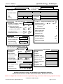
1
Quantum Energy Technologies
Owner’s Manual
OWNER'S MANUAL
Including Installation Instructions And Warranty Information
TO SUIT HEAT PUMP STORAGE WATER HEATER MODELS
Compact:
Split:
150-08ACW-134
200-08ACW-134
270-11AC3-134
340-11AC3-134
270-11AC4-134
340-11AC4-134
340-17ACW-134
150-08ASW-134
200-08ASW-134
270-11AS4-134
340-11AS4-134
340-17ASW-134 (340TIH-134)
(with Recommended Connections for Commercial Models)
FOR ADVICE, REPAIRS AND SERVICE
Australia: 1800 644 705
New Zealand: 0800 402 002
Document Number: QDC0030PD-16.4
(From Series No.SUZ070001 to Series No. SUZ070336)
Date Of Revision: Oct. 2011
Document number: QDC0030PD-16.4
Page 1 of 36
Owner’s Manual
Quantum Energy Technologies
Contents
Section 1: APPLIANCE DETAILS ……………………………………………………………………….. 5
1a: Owner’s Details ………………………………………………………………………………. 5
1b: Installer’s Details 1c: Service History …………………………………………………… 5
Section 2:INTRODUCTION …………………………………………………………………….
2a: One Of The World’s Most Energy Efficient Methods Of Water Heating ……………….
2b: Time Delay On Start ……………………………………………………………………..
2c: Features Of Your Quantum Water Heater ……………………………………………………...
6
6
6
6
Section 3: INSTALLATION DETAILS ...................................................................................
3a: General Installation Requirements .....................................................................................
3a.1: Location ...........................................................................................................................
7
7
7
3a.2: Corrosion Protection........................................................................................................
3b: Air Flow..............................................................................................................................
3c: Evaporator Drain.................................................................................................................
3d: Pressure & Temperature Relief Valve (PTR).....................................................................
3e: Expansion Control Valve (ECV) ........................................................................................
3f: Cold Water Connection .......................................................................................................
3g: Pressure Reducing Valve....................................................................................................
7
7
8
8
8
8
8
3h: Caution Regarding Glass Lining Of Tank ..........................................................................
3i: Suitability For Installation In Frost Areas ...........................................................................
3j: Draining Of Tank ................................................................................................................
3k: Hot Water Connection ........................................................................................................
3l: Tempering Valves ...............................................................................................................
3m: Electrical Connection ........................................................................................................
3m.1: Safety Notes ...................................................................................................................
3n: Refrigeration Connections (Split Models Only).................................................................
3n.1: Refrigeration Tube Sizes .................................................................................................
3o: Caution Regarding Drilling Metal Jacket ...........................................................................
8
8
11
11
11
11
11
12
12
12
Section 4: OPERATING INSTRUCTIONS .............................................................................
4a: Filling The Water Heater ....................................................................................................
4b: Water Quality .....................................................................................................................
4c: Caution When Left Operating But Unused.........................................................................
12
12
12
12
Section 5: SAFETY INFORMATION ..................................................................................... 13
5a: Safety Devices .................................................................................................................... 13
5b: Important Note Regarding PTR Valve ............................................................................... 13
Document number: QDC0030PD-16.4
Page 2 of 36
Owner’s Manual
Quantum Energy Technologies
Section 6: MAINTAINANCE & SERVICE INFORMATION.................................................
6a: The Water Tank ..................................................................................................................
6b: Air Evaporator Coils...........................................................................................................
6c: Sacrificial Anode ................................................................................................................
6d: Service Caution – Before Any Work Is Carried Out ..........................................................
6e: Thermal Overload (Incorporated in Digital Controller) .....................................................
6f: Routine Service ...................................................................................................................
6f.1: Six Month Service (By Owner).........................................................................................
6f.2: Five Year Service (By Authorized Personnel Only) .........................................................
6f.3: Access & Removal Of Sacrificial Anode .........................................................................
13
13
14
14
14
14
14
15
15
15
6f.4: Flushing Of Water Tank ................................................................................................... 15
6f.5: Refrigeration & Thermostat Servicing ............................................................................. 16
Section 7: RECOGNITION OF ABNORMAL OPERATION..................................................
7a: Pressure & Temperature Relief Valve Running .................................................................
7a.1: Continuous Trickle ..........................................................................................................
7a.2: Steady Flow .....................................................................................................................
7b: No Hot Water......................................................................................................................
7c: High Electricity Bills ..........................................................................................................
16
16
16
16
16
17
Section 8: WARRANTY CERTIFICATE ................................................................................ 17
8a: Terms of Warranty .................................................................................................................... 17
8b: Items Not Covered By Warranty ........................................................................................ 18
8c: Before Phoning For Service................................................................................................ 19
Section 9: SPECIFICATIONS .................................................................................................. 20
Section 10: OPERATION & ADJUSTMENT OF THE DIGITAL CONTROLLER ...............
10a: The Buttons .......................................................................................................................
10a.1: SET Button.....................................................................................................................
10a.2: UP Button.......................................................................................................................
10a.3: DOWN Button ...............................................................................................................
10b: Restore Factory Programming ..........................................................................................
22
22
22
22
22
22
10b.1: First Level: Press SET+UP for 6 seconds.......................................................................
10b.2: Second Level: Press SET+DOWN for 6 seconds...........................................................
10b.3: Third Level: Press UP+DOWN for 6 seconds........................................................................
10c: Error Codes .......................................................................................................................
10d: De-Icing............................................................................................................................
10e: Operating Principle...........................................................................................................
10f: Adjusting...........................................................................................................................
10f.1: Time Controller..............................................................................................................
22
23
23
23
23
23
24
24
Document number: QDC0030PD-16.4
Page 3 of 36
Owner’s Manual
Quantum Energy Technologies
Appendix A: TROUBLE SHOOTING GUIDE ON QUANTUM WATER HEATERS ..........
A.1: No Hot Water; Compressor Not Running ........................................................................
A.2: Thermal Cut Out Trips Off Repeatedly ............................................................................
A.3: No Hot Water; Compressor Running ...............................................................................
A.4: Shortage Of Hot Water .....................................................................................................
A.5: Testing Undercharge Or Overcharge Of Refrigerant .......................................................
A.6: Water Temperature, Condensing Pressure & Amperage – R134a Units..........................
A.7: Suction Pressure – R134a Units .......................................................................................
A.8: Signs Of Correct Charge...................................................................................................
A.9: Signs Of Undercharge.......................................................................................................
28
28
28
29
30
30
30
30
31
31
A.10: Signs Of Overcharge....................................................................................................... 31
A.11: Technical Data For Service Personnel – SIAM Compressors – R134a ......................... 31
Appendix B: RECOMMENDED CONNECTIONS FOR COMMERCIAL MODELS .......... 32
WARRANTY CARD ............................................................................................................... 33
NOTES (Owner’s Use) ............................................................................................................. 35
List of Figures
Figure 1: Installation Diagram (Compact Systems)..................................................................
Figure 2: Installation Diagram (Split Systems) ........................................................................
Figure 3: Specifications & Dimensions ....................................................................................
Figure 4: Split Fin Coil Evaporators ........................................................................................
Figure 5: Picture of time controller................................................................................ ...........
Figure 6: Wiring Diagram –150/200-08ACW-134 & 270/340-11AC3-134............................
Figure 7: Wiring Diagram –150/200-08ASW-134 & 340-17ASW-134 (340-TIH-134).........
Figure 8: Wiring Diagram –340-17ACW-134……..................................................................
Figure 9: Indicator –340-17ACW-134……..............................................................................
Figure 10: Wiring Diagram-with Timer –150/200-08ACW-134 & 270/340-11AC4-134 …
9
10
20
21
24
25
25
26
26
27
Figure 11: Wiring Diagram-with Timer –150/200-08ASW-134 & 270/340-11AS4-134 …...
Figure B1: Hydronic Connection for 340-17ACW3-134…….................................................
Figure B2: Hydronic Connection for 1020-17ACW-134…….................................................
27
32
32
Document number: QDC0030PD-16.4
Page 4 of 36
Owner’s Manual
Quantum Energy Technologies
Section 1: APPLIANCE DETAILS
For future convenience, please fill in the following details and retain with your original invoice.
1a: Owner’s Details
Surname: ……………………………………
Given Name(s): ….………………………....
Address: ……………………………………………………………………………...…………
Town/Suburb: ……………………………………………………………………..……………
State/Territory:………………………………
Postcode: ……………………………………
Date of Purchase: .….……….………………
Purchased From: ………………………………………..………………………………….……
Model: ..……………………………………..
Serial Number: ………………..…………….
Date of Manufacture: .……………………………………………………………….…………..
(Details on Data Plate on water heater)
1b: Installer’s Details
Date of Installation: …………………………
Installer’s Name: ……………………………
Address:…………………………………….……………………………….…………….…..…
Installer’s Signature: …………………………………….………………….……………….….
1c: Service History
Date of Service: .............................................
Serviced By: …………….………………….
Work Carried Out: …………………….………………………………………………….…….
Signature of Service Agent: .……………………………….…………………………….……..
Date of Service: .............................................
Serviced By: …………….………………….
Work Carried Out: …………………….………………………………………………….…….
Signature of Service Agent: .……………………………….…………………………….……..
Date of Service: .............................................
Serviced By: …………….………………….
Work Carried Out: …………………….………………………………………………….…….
Signature of Service Agent: .……………………………….……………………………….…..
Document number: QDC0030PD-16.4
Page 5 of 36
Quantum Energy Technologies
Owner’s Manual
Section 2: INTRODUCTION
QUANTUM ENERGY TECHNOLOGIES
2a: One Of The World’s Most Energy Efficient Methods Of Water Heating Production
We thank you for your decision to purchase a Quantum Energy Technologies Heat Pump Water
Heater, which will reward you with many years of low energy hot water production.
QUANTUM ENERGY TECHNOLOGIES Pty Ltd designs and manufactures energy efficient heat
pump water heaters. The simple way to explain the advantage of this heater is that it saves energy
in any weather, even at night.
For example, one of the models uses 1kW of electrical energy, however, they are able to put up to
3.6kW of heat energy into the water with 20°C ambient air. The system can save up to 75% of
conventional water heater’s energy utilisation; greatly assisting in the worldwide greenhouse gas
reduction campaign.
As the name indicates, a Heat Pump is a machine that pumps heat from a low temperature source
to a high temperature reservoir. It has a cold side to absorb heat at low temperatures and a hot side
to deliver heat at high temperatures.
Quantum heat pump water heater has an air conditioning coil as the cold side of the refrigeration
circuit. This coil absorbs the heat from air that is forced through it by means of the fan. The
Compact design is installed like a conventional electric water heater i.e. the electrical and
plumbing connections are completed in the same manner.
There is also the Split design, which can be used to recover heat from a warm area like the roof
space or the kitchen. The remote fan coil (energy collector) absorbs the heat energy from the
warm air. Alternatively, the waste heat from the building can be used as the heat source.
QUANTUM heat pump water heaters can save energy in countries all around the world. They are
used in all weather conditions for domestic, commercial and industrial applications, and are
regarded as the most energy efficient and practical water heaters available.
This is your assurance that you have purchased one of the highest quality water heaters on the
market and the one that will provide continuous hot water for all your needs – safely,
economically, and for many years to come.
2b: Time Delay On Start
NOTE: The system has a 10-minute time delay on start or restart. When the power is first
connected or after a disconnection then re connection, the time delay on start will occur. The
compressor and fan will not operate until the completion of this time delay period.
2c: Features Of Your Quantum Water Heaters
1.
Fully welded steel tank with class X vitreous enamel lining for superior corrosion
resistance and longer life.
2.
Indirect heat transfer eliminates cross contamination and tank hot spots.
3.
No electrical element. The safest and one of the most energy efficient Heat Pump systems
in the world, especially in cold weather, the efficiency is higher than any other solar/heat
pump systems on the market.
4. Able to save more money than any other solar/heat pump systems on the market.
Document number: QDC0030PD-16.4
Page 6 of 36
Quantum Energy Technologies
Owner’s Manual
Warranty Return Card
Enclosed you will find a warranty card – please fill in the details and return to Quantum. This will
ensure prompt service under warranty, if required (see Section 8 for terms of warranty).
Section 3: INSTALLATION DETAILS
3a: General Installation Requirements
This water heater must be installed by a licensed tradesperson, and in accordance with
1. AS 3500.4, National Plumbing And Drainage Code, Part 4: Hot Water Supply Systems.
2. AS 3500.4.2, National Plumbing And Drainage Code, Part 4.2: Hot Water Supply Systems
– Acceptable Solutions.
3.
Other relevant Australian and New Zealand Standard, Industry or Local Water Supply
regulations or codes for mains pressure storage tanks.
Note: This water heater is not suitable for pool heating or building heating.
3a.1: Location
The water heater should be located as close as possible to the most frequently used hot water
outlets. Adequate access must be made for service to the heat pump, water thermostat, relief valve
and anode. Ensure that the specification label is clearly visible. The front service cover of the heat
pump section (on top of tank) must be accessible from the front of the heater; this must NOT face
the wall. The fan MUST NOT be up against a wall (minimum clearance 500mm).
The Compact model has a noise level similar to an air conditioner’s outdoor unit (52dBA @ 1.5
metre); therefore locating the unit away from bedrooms or living areas is recommended (both the
owners & any neighbors).
Note: All models are equipped with a sacrificial anode, accessible through the top cover. We
recommend allowing 400mm above the top of the water heater (if possible) for clearance to
replace the anode.
The water heater should be placed on a 650mm x 650mm plinth if installed on a floor subject to
wet conditions or outdoors. A properly drained overflow tray should be used where property
damage could occur from water spillage. (See AS3500.4 for further details.)
Note:
The warranty does not cover damage due to leakage of the water heater
3a.2: Corrosion Protection
Fittings and the Shell Surface in contact with the water are to be galvanically compatible. Sealants
and / or Teflon plumbing tape should be used on potentially galvanically incompatible fittings.
This is to protect against possible electrolytic corrosion between the metals (where moisture
penetration could occur due to incorrectly or poorly sealed fittings).
3b: Air Flow
The air source models (compact and split) extract the required heat from air being drawn through
their Fin Coil Evaporator. This produces cold exhaust air as a by-product. In order for the heaters
to operate efficiently, good ventilation of the proposed location for the compact models or the
split models’ separate evaporator is required. This is to provide warm air as a heat source and to
remove the cold air being produced. The Compact therefore is best located externally, however a
large double garage (minimum of 120 cubic meters) with some natural ventilation may also be
Document number: QDC0030PD-16.4
Page 7 of 36
Owner’s Manual
Quantum Energy Technologies
acceptable. The separate evaporator in the split models could be located externally or in a large
well-ventilated ceiling space or garage.
3c: Evaporator Drain
During operation a certain amount of condensate water will flow from the evaporator drain. If
allowed to simply flow out of the outlet, this water may pool below the unit and can cause
problems to the water heater and/or area around it. The evaporator drain on both the Compact and
Split Air units should be drained to a suitable location. This can be accomplished with a length of
hose or pipe but must not be connected directly to the PTR valve or expansion valve drain.
3d: Pressure & Temperature Relief Valve (PTR)
The Pressure and Temperature relief valve (see tank data plate for rating), which is supplied with
the unit, must be fitted and made accessible so that the release mechanism can be operated and, if
required, the valve replaced. The outlet of the PTR valve must be suitably drained to remove the
water discharged during the normal heating cycle. The valve thread is RP ½” / 15mm and must be
installed into the top front socket.
Warning: A separate drain line must be run for this relief valve. It is not permitted to couple the
drain lines from the relief valve and evaporator into a single common line. The use of a tundish
under the evaporator drain with this then connected to the drain of the PTR valve is acceptable.
3e: Expansion Control Valve (ECV)
Where an Expansion Control Valve is fitted to the cold water supply, the ECV should be rated at
150kPa lower than the Pressure & Temperature Relief valve (PTR). It is a State requirement for
SA & QLD that an ECV be fitted on the cold water supply line between the non- return
valve and the water heater.
3f: Cold Water Connection
An approved isolating valve, approved non-return valve, line strainer (optional but recommended),
and union must be fitted between the supply main and the RP ¾ / 20mm socket in the water heater.
All fittings must be approved by the relevant Authority (refer to Figures 1 & 2).
3g: Pressure Reducing Valve
This water heater is designed for direct connection to a maximum water supply pressure of 800kPa.
Where the mains pressure can exceed or fluctuate beyond this pressure, a pressure-limiting device
(complying with AS1357) must be fitted in the cold-water supply line. This device must be
installed after the isolating valve and set at or below 500kPa (or 350kPa if a 850kPa expansion
control valve fitted). An ECV is fitted when the water supply has a tendency to form scale. This
type of water is referred to as scaling water because calcium carbonate is deposited out of the
water onto any hot metallic surface. The fitting of an ECV is mandatory in WA, SA and some other
areas of Australia as dictated by local regulations.
3h: Caution Regarding Glass Lining Of Tank
When making the hot and cold water connections to the tank care should be taken not to apply
excessive strain as damage to the tank spigots or glass lining may occur.
3i: Suitability For Installation In Frost Areas
The R134a refrigerant used has a boiling point of –26°C so there is no risk of damage to the heat
pump from frost. Performance may be reduced in very low temperatures but the system will not
be damaged by such climatic conditions.
Document number: QDC0030PD-16.4
Page 8 of 36
Quantum Energy Technologies
Owner’s Manual
Figure 1: Installation Diagram (Compact Systems)
Thermo Siphon Trap
100 mm Min
Orientation
if multiple
Compact units are
being installed.
Wall
Condensation
Drain
500 mm
Min
Power Cord
15°
Water
Connections
32°
i.e. fan to face out.
200-500 mm
PTR Valve
Front Access
1.
2.
3.
4.
NOTE:
In installing single Compact units, the fan should point out from, or along, the wall.
If the fan has to point towards to the wall, the distance between the unit and the wall should be at a
minimum of 500mm.
In installing multiple Compact units, the fan should not point out to the unit adjacent, so that cold air being
discharged from one unit is not drawn in by the one next to it.
The space between multiple units should be a minimum of 200mm for air flow, but 500mm is recommended
for the convenience of service.
Document number: QDC0030PD-16.4
Page 9 of 36
Quantum Energy Technologies
Owner’s Manual
Figure 2: Installation Diagram (Split Systems)
100 mm Min
Wall
Power
Connection
35°
Water
Connections
200-500 mm
32°
PTR Valve
…
Front Access
Note: The pipes connected to the water heater’s cold water and hot water connections
should not be the flexible/soft type.
Document number: QDC0030PD-16.4
Page 10 of 36
Owner’s Manual
Quantum Energy Technologies
3j: Draining Of Tank
Consideration should be given to the possible necessity of draining the tank at some point.
Draining of the tank can be accomplished by the connection of a hose to the cold water inlet and
running to a suitable drain. It will be necessary to disconnect the hot water outlet or PTR valve to
relieve any partial vacuum created as the water flows out.
3k: Hot Water Connection
The hot water pipe should be connected to the RP ¾ / 20mm socket as shown in the Installation
Diagram (Figures 1 & 2). If desired, a thermo siphon trap can be installed at the hot water outlet
to further reduce heat loss (a “U” shaped loop will form such a trap – see Figures 1 & 2). It is
recommended that all hot water lines be insulated. NOTE: Plugs are supplied with the water
heater to plug off the inlet / outlet entries that are not required. Ensure that adequate sealing is
applied to the plugs for a tight, leak proof seal.
3l: Tempering Valves
The tempering valve should be fitted on the hot water outlet of the Quantum units to reduce water
temperature to the temperature designated in (e.g., 50°C as per the plumbing code). The high
performance valves suitable for “Solar” type water heaters are recommended to be used. Standard
tempering valves may also be used, but it may be not function as well as the high performance
ones.
3m: Electrical Connection
Quantum water heaters are designed for single-phase 220/240V 50Hz A.C supply only. All
electrical work must be conducted by a certified electrician according to the local regulations and
AS3000. A 10 or 15-amp circuit breaker must be installed at the power supply for the hot water
units up to 0.8kW or 1.7kW, respectively. The power connection rating for Quantum water
heaters up to 1.1kW is 220-240VAC 50Hz 10A, and 15A for the 1.7kW models.
A separate circuit breaker is recommended for each unit in the case of multiple installations.
It is not recommended to wire the system to an earth leakage circuit breaker. There is lot of
moisture present while in operation and this can lead to nuisance tripping.
The connection will require an approved, standard 240V On / Off switch or Junction Box in close
proximity to the heater. The unit should be connected to Standard Domestic tariff. Off Peak
connection is NOT recommended for Quantum heat pump units. If the unit is connected to an
“Off Peak” connection, the minimum power availability must be at least 18 hours per day.
The fitted power cord is not to be removed; this cord should be connected with the building
wiring in an On/Off switch enclosure or Junction Box. Faulty wiring may void the warranty if
damage has been sustained to the compressor or heat pump from such faulty or sub-standard
wiring.
3m.1: Safety Notes
Note.1: This water heater is fitted with a thermostat and over-temperature energy cut-out (both
incorporated into the digital controller). Under no circumstances should the water heater be
operated without both of these devices being in the circuit. Only a qualified electrician or the
manufacturer should carry out replacement.
Note.2: If the supply cord is damaged, the manufacturer or its service agent or other similarly
qualified person must replace it in order to avoid hazard.
Caution: The water heater must be filled with water before turning on the electricity
Document number: QDC0030PD-16.4
Page 11 of 36
Quantum Energy Technologies
Owner’s Manual
3n: Refrigeration Connections (Split Models Only)
Refrigeration pipe work is very specialized and should only be completed by a licensed
tradesperson.
Maximum refrigeration pipe length from the tank connections to the evaporator is 9m.
If the evaporator is mounted below the tank connection point, then a suitable oil trap needs to be
installed on the suction line between the evaporator and the heat pump.
3n.1: Refrigeration Tube Sizes
Copper Tube Size Inlet
3
150/200-08ASW-134
/8 Inch (9.5mm)
3
270/340-11AS4-134
/8 Inch (9.5mm)
3
340-17ASW-134
/8 Inch (9.5mm)
Model
Copper Tube Size Outlet
3
/8 Inch (9.5mm)
1
/2 Inch (12.7mm)
5
/8 Inch (16.0mm)
Copper Tube Size – Outlet
(if evaporator below tank level)
3
/8 Inch (9.5mm)
/8 Inch (9.5mm)
1
/2 Inch (12.7mm)
3
3o: Caution Regarding Drilling Metal Jacket
This is extremely important and MUST be adhered to without exception!
DO NOT DRILL ANY HOLES IN OUTER METAL JACKET
DAMAGE TO REFRIGERATION LINES MAY RESULT
Section 4: OPERATING INSTRUCTIONS
4a: Filling The Water Heater
Open all hot water taps. Open isolating valve at the cold-water inlet and allow the water heater
to fill until water flows through the system. Close each hot water tap after the air is expelled from
its line.
4b: Water Quality
Your Quantum water heater has been manufactured to suit the water conditions of most Australian
and New Zealand metropolitan supplies. Please note that harsh water supplies can have a
detrimental effect on the water heater and its life expectancy. If you are unsure about your water
quality you can obtain information from your local water supply authority.
By using the correct anode this water heater can be used in areas where the Total Dissolved Solids
(TDS) content of the water supply is up to 2500 mg/L. In areas where the TDS exceeds 750mg/L it
is possible that the magnesium alloy anode (supplied in the heater) may become over reactive. To
alleviate this, the magnesium alloy anode should be replaced with an aluminum alloy anode
(Note: Quantum does not supply this).
4c: Caution When Left Operating But Unused
If the water heater is left in an operating condition but unused for two weeks or more, a quantity
of hydrogen gas (which is highly flammable) may accumulate in the top of the water cylinder. To
dissipate this gas safely it is recommended that a hot tap be turned on for several minutes at a sink,
basin or bath, but not a dishwasher, clothes washer or other appliance. During this procedure there
must be no smoking, open flame or any other electrical appliance operating nearby. If hydrogen
gas is discharged through the tap it will probably make an unusual sound similar to air escaping.
Document number: QDC0030PD-16.4
Page 12 of 36
Owner’s Manual
Quantum Energy Technologies
Section 5: SAFETY INFORMATION
DO NOT TURN ON POWER UNLESS THE TANK IS FULL OF WATER
5a: Safety Devices
WARNING: For safe performance this water heater is fitted with:
1.
Digital Controller.
2.
A thermostat (connected to the digital controller) to manage water temperature.
3.
A thermostat (connected to the digital controller) to manage compressor temperature.
4.
A non self-setting thermal cut out (incorporated into the digital controller).
5.
Combination Pressure & Temperature relief valve.
These devices must not be tampered with or removed.
The water heater must not be operated unless each of these devices is fitted and in working
order.
This appliance is not intended for use by young children or the infirm without supervision –
young children should be supervised to ensure that they do not play with the appliance.
5b: Important Note Regarding PTR Valve
The Pressure & Temperature relief valve should be checked for adequate performance or replaced
at intervals not exceeding 5 years, or less in areas where there is a high incidence of water
deposits. Providing there is some discharge from the relief valve during each heating cycle there
is no requirement to manually activate the release mechanism on the relief valve. There is a
possibility that manually opening the relief valve may allow contamination / grit etc to settle in
the valve seat causing continuous leakage. If the relief valve is operated manually it should be
done with care.
The Pressure & Temperature relief valve and the drain outlet pipe must not be sealed or blocked.
It is normal for small amounts of water to leak from the valve during each heating cycle.
Section 6: MAINTAINANCE & SERVICE INFORMATION
Your Quantum water heater is a completely sealed refrigeration system, similar to a household
refrigerator. The maintenance program to be employed on your Quantum is not much different to
that required for the maintenance of a standard electric water heater. However, Quantum
warranty may be void if any of the following conditions are not met or if the refrigeration
lines or components are damaged or altered in any unauthorized way.
6a: The Water Tank
The water tank must not be drilled or punctured. Drilled holes or punctures may damage the
refrigeration pipes located on the skin of the water tank. The Quantum tank is a patented design
and in fact forms the condenser of the unit; i.e. it is the hot side of the refrigeration circuit. The
coils wound around the outside wall of the tank heat the tank more efficiently than any other
water heater design. The coils are not in contact with the water so they never corrode or suffer
from scaling, meaning the efficiency of the tank will not diminish.
Document number: QDC0030PD-16.4
Page 13 of 36
Quantum Energy Technologies
Owner’s Manual
6b: Air Evaporator Coils
Quantum water heaters use evaporator coils to extract heat from the air. The coil is extremely
efficient in warm humid weather; however, as temperatures drop to ten degrees or less the coil
will begin to collect ice. The coil has been designed with "heat injection" to defrost the coil under
such conditions. The heat injection cycle is automatic and is managed by the digital controller. It
is important that the air inlet vents are kept clean. Restriction of air-inlet or outlet vents
may void warranty if the system has been damaged because of insufficient airflow.
6c: Sacrificial Anode
A sacrificial anode is fitted inside the vitreous enamel lined cylinder. Its purpose is to help protect
the cylinder from the corrosive effects of water. Normally, the sacrificial anode should be
inspected every fifth year and replaced if necessary. In areas where “hard water” or poor quality
water conditions exist, the sacrificial anode must be inspected every second year. Replacement
anodes must meet Quantum quality specifications and must be appropriate for local water
conditions. The anode socket in the top of the tank is an RP 3/4 / 20mm thread, an 11/16” socket
wrench is required to unscrew it
6d: Service Caution – Before Any Work Is Carried Out
Before any electrical components are inspected the System MUST be turned off at the power
switch / hot water circuit breaker. Do not touch wiring or any electrical components without
supervision or training to Australian (or equivalent) standards.
6e: Thermal Overload (Incorporated in Digital Controller)
All models are fitted with a digital controller for heat pump management. One function of the
digital controller is to initiate a shut down and lockout if the compressor reaches a temperature of
105°C. The system will not automatically restart from this. To reset the system the “SET”
button on the digital controller must be pressed (hold for 6 seconds). Turning the power off then
back on will also perform a reset.
6f: Routine Service
Serving requirements and timing for Quantum heat pump hot water systems.
MAINTENANCE
REQUIRED
Check PTR Valve
6
12
6
12
6
12
YEAR AND MONTH FOR SERVICE
4
5
6
7
6 12 6 12 6 12 6 12
x
x
x
x
x
x
x
1
2
3
Replace PTR Valve
Replace Anode
Flush Water Tank
Check Of Electrical
Check Of Refrigeration
Check Of Thermostats
Check For Any Corrosion
Check of Plumbing
x
x
x
x
x
x
x
x
x
x
x
x
x
x
x
8
9
10
6
12
6
12
6
12
x
x
x
x
x
x
x
x
x
x
x
x
x
x
6f.1: Six Month Service (By Owner)
To be carried out every six months. Operate the Pressure & Temperature relief valve for
approximately 10 seconds by activating the release mechanism on the valve to ensure water is
released to waste through the relief drainpipe.
Document number: QDC0030PD-16.4
Page 14 of 36
Owner’s Manual
Quantum Energy Technologies
It is very important that the mechanism is operated gently. Check to ensure the valve closes
correctly.
Note: providing some hot water discharge has been observed from the relief valve during normal
heating cycles, manually activating the valve is not necessary and could cause contamination / grit
to lodge in the relief valve seat causing constant leakage.
An inspection for any obvious signs of corrosion of the outer case or air intake grills should also
be conducted.
6f.2: Five Year Service (By Authorized Personnel Only)
The five-year service should be carried out by a licensed tradesperson every five years. It is
recommended that your local Quantum distributor or service agent carry out this service. The
service should include the following: 1.
Replace the Pressure & Temperature Relief valve.
2.
Replace the anode.
3.
Flush the water heater.
4.
Checking of the refrigeration system.
5.
Checking of thermostats, digital controller and electrical components.
If in doubt, contact Quantum Energy Technologies for your nearest distributor or service agent.
Our website www.quantumenergy.com.au and www.quantumenergy.co.nz also provide an up
to date list of Quantum distributors.
6f.3: Access & Removal Of Sacrificial Anode
The anode can be accessed via the heat pump section, to remove.
1.
Turn off power to the unit, cut into water valve, open PTR valve to release pressure on the
system.
2.
Remove the screws around the top cover of the heat pump & remove the heat pump top
cover.
3.
For easier access the front inspection panel on the heat pump section should also be
removed.
4.
Locate and remove the plastic plug through the centre of the heat pump chassis.
5.
The anode head is now accessible and can be unscrewed with a suitable 11/16” socket
wrench.
6.
Once unscrewed the anode can be drawn out through the top of the tank / heat pump
section.
7
The new anode can then be fitted and the heater reassembled.
6f.4: Flushing Of Water Tank
As with other hot water heater tanks, dissolved solids in the water or scale may accumulate in the
bottom of the water tank forming sludge. This is generally less of a problem with Quantum units
as no internal elements or burners are used.
If such sludge build-up does occur the following procedure can be followed to clean out the tank.
1. Turn Off power to the unit.
2. Turn Off water supply to the unit.
Document number: QDC0030PD-16.4
Page 15 of 36
Owner’s Manual
Quantum Energy Technologies
3. Remove the blanking plug (brass fitting) from the unused inlet (normally on the right
hand side for left hand connected tanks) – the inlets are at the bottom of the tank 70mm up
from the base.
4. Remove the blanking plug from the unused hot water outlet (normally on the right hand
side for left hand connected tanks) – the outlets are at the top of the tank.
5. Allow the water to drain from tank, while the water is draining a non-metallic rod may be
inserted through the open cold-water inlet and used to break up any sludge and assist in its
removal.
6. Care should be exercised during this procedure so as not to damage the glass lining of the
tank. The use of metal rods should not be used and plastic or wooden rods used instead.
7. Turning the cold water supply back on while the tank is emptying or after the tank has
drained and continuing with the mechanical agitation will further assist with the removal
of the sludge.
8. Once the tank has been cleaned, as much as possible, the cold water should be turned off
again and the blanking plugs refitted. Care should be taken to ensure good a hydraulic seal
is maintained – the use of plumbing tape will be required.
9.
When the unit is fully reassembled the cold water supply and power supply can be turned
on and the unit allowed to reheat.
6f.5: Refrigeration & Thermostat Servicing
Qualified refrigeration technicians only should service the heat pump. The information provided
in Appendix A: Trouble Shooting Guide will provide the necessary information for qualified
personnel to service this part of the unit.
Section 7: RECOGNITION OF ABNORMAL OPERATION
7a: Pressure & Temperature Relief Valve Running
It is not unusual for the Pressure & Temperature Relief valve to allow a small quantity of water to
escape during the heating cycle. The amount of discharge will depend on hot water usage. As a
guide, if it discharges more than 20 litres of water in 24 hours then there may be a problem.
7a.1: Continuous Trickle
Likely caused by a build up of foreign matter. Try gently operating the release mechanism on the
Pressure & Temperature Relief valve for a few seconds. This may dislodge any small particles of
foreign matter and rectify the fault.
7a.2: Steady Flow
Likely causes are excessive water supply pressure (500kPa Pressure Limiting valve should be
fitted), a faulty Pressure & Temperature Relief valve, a faulty or non existent pressure limiting
valve or a faulty Thermostat / Digital Controller. Turn off the electricity supply and contact your
Quantum distributor or service agent.
7b: No Hot Water
1.
Is the Electricity switched on? Check that the isolating switch, to which the Quantum
is connected, is on. Check that the switch marked “Water Heater” in the switchboard is
on. Are all circuit breakers on? If on Off Peak, is the meter switching on when it should?
If the system is connected to some form of Off Peak metering, running out of hot water
Document number: QDC0030PD-16.4
Page 16 of 36
Owner’s Manual
Quantum Energy Technologies
can be quite common – Off Peak tariffs are not recommended for Quantum water heaters.
2. Check that the thermal overload (on the digital controller) has not been tripped. If so
press the “Set” button (hold for 6 seconds) to reset it.
3.
Is the Pressure & Temperature Relief valve discharging too much water? See Section 7a:
"Pressure & Temperature Relief Valve Running".
4. Do you have the correct size water heater for your requirements?
available from your Quantum supplier.
5.
Sizing details are
Is one outlet (such as the shower) using more hot water than you think? Carefully
review the family's hot water usage and if necessary check the shower flow rates with a
bucket and a watch. If it is not possible to adjust water usage patterns, an inexpensive
flow control valve can easily be fitted to the shower outlet.
7c: High Electricity Bills
1.
Is the Pressure & Temperature Relief valve discharging too much water?
7a: "Pressure & Temperature Relief Valve Running”.
2.
Is one outlet (such as the shower) using more hot water than you think?
"No Hot Water”.
See Section
See Section 7b:
3.
Is there a leaking hot water pipe or dripping hot water tap? A small leak can waste a large
quantity of hot water.
4. Replace faulty tap washers and have your plumber rectify any leaking pipe work.
5. Have any new appliances been installed that might be using the extra power?
6.
If there are no water leakages around the building and no excessive usage of hot water, yet
electricity bills are higher than normal (without any other appliance being responsible)
then it may indicate a problem with the water heater. Contact your nearest Quantum
distributor or service agent.
Section 8: WARRANTY CERTIFICATE
8a. Terms Of Warranty
QUANTUM WATER HEATERS are manufactured by Quantum Energy Technologies Pty Ltd. QUANTUM ENERGY
TECHNOLOGIES PTY LTD (the Company) WARRANTS “THIS QUANTUM ENERGY SYSTEM” (the unit)
against faulty workmanship, materials and defects in manufacturing as here in after provided: 1.
Storage tank integral with condenser coil: - Warranted for a period of five (5) years from the date of installation
2.
Refrigeration pipe work, refrigeration valves, compressor, fan coil and motor, electrical components including
thermostats, digital controller, solenoids, wiring and controls: - warranted for a period of two (2) years from date of
installation. Plumbing valves supplied with the unit are covered by their respective manufacturers’ warranties.
3. Labour, delivery and / or transportation: - Where the Company considers it necessary to repair or replace any
component part covered by the warranty, the consequential labour, delivery and / or transportation services will be
provided free of charge to the owner within a fifty-kilometre radius from where the unit was purchased. Customers
outside this area will be subject to freight and traveling charges incurred by the service agent carrying out the work.
The date and time of the commencement of such warranty work will be at the discretion of the Company. Quantum
does not warrant that such repair work will take place within any particular period. A call out fee applies to any
warranty calls made outside normal QUANTUM business hours.
The Company’s liability under this warranty shall be limited to the free replacement or repair of any defective
component parts of the unit and shall not cover any consequential loss or damage arising out of any such defect.
Document number: QDC0030PD-16.4
Page 17 of 36
Quantum Energy Technologies
Owner’s Manual
THE WARRANTY SHALL NOT APPLY IN ANY OF THE FOLLOWING EVENTS:
1.
The unit is installed by an non licensed Plumber with inadequate technical skills or training to perform the task;
2.
The installer does not issue a Plumber’s Certificate of Compliance in the State of Victoria.
(State Rebate’s in Victoria will not be paid unless a Certificate of Compliance number is provided).
3.
Where alterations, addition or repairs to the unit are carried out by persons unauthorized by the Company;
4.
Accident or in the opinion of the Company, misuse and / or abuse of the unit;
5. Where the anode has not been periodically replaced in accordance with the directions in this Owner’s Manual or
where in the opinion of the Company, it has been incorrectly replaced;
6.
Where the loss or damage is, in the opinion of the Company, due to the failure to install, operate and / or maintain
the unit in accordance with any of the directions contained in this Owner’s Manual.
THIS WARRANTY DOES NOT COVER LOSS OR DAMAGE TO THE UNIT OCCASIONED BY ANY OF THE
FOLLOWING PERILS: 1.
Riot, Civil Commotion or Any Consequence of War or Invasion;
2.
Acts of God;
3.
Theft or Larceny.
IMPORTANT
This warranty is in addition to all other rights and remedies available to the consumer under the Trade Practices Act
1974 as amended and other relevant local laws and shall not be taken as applying to exclude, restrict or modify such
rights or remedies in any manner whatsoever.
Where the unit is of a kind not ordinarily acquired for personal, domestic or household use, then the liability of the
Company for beach of any condition or warranty implied by the aforementioned statues (other than a condition or
warranty implied by Section 69 of the Trade Practices Act or any corresponding Section on any other enactment in any
State or Territory for the time being enforced) is limited to any one or more of the following as the Company decides: 1.
2.
3.
4.
The replacement of the unit or the supply of an equivalent unit;
The repair of the unit;
The payment of the cost of replacing the unit or of acquiring an equivalent unit;
The payment of the cost of having the unit replaced
8b: Items Not Covered By Warranty
Service calls due to:
□
•
Dirty Filters.
•
Blown Fuses
•
Incorrect Operation.
•
Tripped Circuit Breakers.
•
Main Isolator Switched Off.
•
Blocked Drains (Evaporator or PTR Valve).
□
Failure to start due to voltage conditions or other damage due to inadequacy or interruption of
electrical service.
□
Damage caused by accident, misapplication and abuse or tampering.
□
Damage caused by use in a corrosive atmosphere (e.g. such as coastal regions).
□
Filter cleaning and / or replacement, unless defective.
Document number: QDC0030PD-16.4
Page 18 of 36
Owner’s Manual
Quantum Energy Technologies
□
Cleaning / maintenance of the water heater unit.
□
Calls made to check the operation of a unit, which is found to be working satisfactorily.
□
Remounting or relocating equipment due to ground subsidence.
□
Modifications to system after installation due to changes in requirements.
□
Relocation of equipment due to complaints of noise level or inappropriate location.
No responsibility shall be accepted for damage to the system or property, if it is found that
continued use of a faulty system has occurred.
No responsibility shall be accepted for delays due to: •
Unavailability of parts from suppliers.
•
Extreme delays due to unusually high demand for service.
8c: Before Phoning For Service
Please check the following: •
Have all the above mentioned items been checked and adhered to?
•
Have you checked through all items in Sections 6 & 7 of this manual?
•
Has the main isolation switch / circuit breaker / hot water switch been turned on?
•
Have any fuses in the switchboard blown?
•
Is the air filter clean?
Warranty shall be carried out during normal business hours 08:00 hours (08:00 AM) to 16:30
hours (04:30 PM) Monday to Friday. Warranty covers travel within a 50-klm distance from the
place of purchase, distributor or service agent’s premises. Any additional travel costs are at the
expense of the customer.
Document number: QDC0030PD-16.4
Page 19 of 36
Quantum Energy Technologies
Owner’s Manual
Section 9: SPECIFICATIONS
Figure 3: Specifications & Dimensions
C
C
C
A
A
A
B
B
B
70mm
Model Number
150-08ACW-134
200-08ACW-134
270-11AC3/4-134
340-11AC3/4-134
340-17ACW-134
150-08ASW-134
200-08ASW-134
270-11AS4-134
340-11AS4-134
340-17ASW-134
(340TIH-134)
70mm
70mm
Mass
(Empty)
(Kg)
Mass
(Full)
(Kg)
R134a
Charge
(gm)
100
115
250
315
135
170
190
90
105
120
155
165
Dimensions(mm)
Power
Input
(W)
Nominal
Capacity
(Lt)
660
660
125
175
1650
1650
A
1620
1950
B
975
1305
C
540
540
405
510
530
240
305
390
495
1850/1900
1850/1900
2650
1650
1650
1900
1900
1900
2200
2240
1545
1875
1765
2060
1190
1490
1490
975
1305
1190
1490
650
650
650
540
540
986
986
1660
660
660
250
315
315
125
175
650
650
986
986
250
315
505
2650
2110
1490
650
1660
315
Model
Evaporator Dimensions
Evaporator
Weight
Evaporator Fan
Noise @1.5 mtr
Air Flow
Litres/Second
150/200-08ACW-134
270/340-11AC3/4-134
340-17ACW-134
150/200-08ASW-134
270/340-11AS4-134
340-17ASW-134
Internal
Internal
Internal
430×380×120 mm
480×430×120 mm
655×580×380 mm
N/A
N/A
N/A
15kg
18kg
35kg
50dBA
52dBA / 48dBA
58dBA
48dBA
50dBA
58dBA
415
550
800
460
600
880
Document number: QDC0030PD-16.4
Page 20 of 36
Quantum Energy Technologies
Owner’s Manual
Figure 4: Split Fin Coil Evaporators
D
B
Air Flow
A
Refrigeration
Connection
C
Power Cable
Refrigeration
Connection
100
110
50
150
40
Dimensions (mm)
Model
A
B
C
D
150/200-08ASW-134
440
445
445
310
270/340-11AS4-134
340-17ASW-134
(340TIH-134)
440
510
485
330
500
635
660
440
A qualified refrigeration technician must install the Split Air model. While the plumbing and
electrical work is the same as the Compact, this unit also requires on site refrigeration work.
Document number: QDC0030PD-16.4
Page 21 of 36
Owner’s Manual
Quantum Energy Technologies
Section 10: OPERATION & ADJUSTMENT OF THE DIGITAL CONTROLLER
Caution: Alteration of the Digital Controllers programming & settings without authorisation from
Quantum Energy Technologies will void your warranty. This section is provided ONLY for
qualified refrigeration technicians to assist in servicing, repairs or trouble shooting.
10a: The Buttons
Use In Conjunction With The Layout Diagram Fig:5 And Wiring Diagrams Fig: 6&7&8&10&11.
10a.1: SET BUTTON
a) To enter the settings node, press the SET button 3 times; the display will show H55, this is
the water temperature cut out set point. Pressing the UP or DOWN button will adjust the set
point from 10℃ to a maximum setting of 62℃ (factory setting 55℃).
b) Press & hold for 6 seconds to enter the de-icing mode. If display shows “OFF” press & hold
for another 6 seconds to exit this mode. (Note this may cause system malfunction so avoid
using).
c) Pressing the SET button (hold for 6 seconds) will perform a manual reset of the system if
required i.e. after a 105℃ Thermal Trip. Turning power off to the system, them back on will
also reset it.
10a.2: UP BUTTON
a) This key becomes operational after entering the settings mode above.
b) Press 3 times to display Axx (the compressor temperature). Push again to display bxx
(evaporator temperature) or again for Cxx (ambient temperature).
c) During the time delay start period, press & hold for 3 seconds to force a compressor start.
When the compressor is running, press & hold for 3 seconds to force a compressor
shutdown.
10a.3: DOWN BUTTON
a) This key becomes operational after entering the settings mode above.
b) Press & hold for 3 seconds to simultaneously open the de-ice valve and liquid injection
valve; the valves will close 10 seconds later.
c) When compressor is running, press 3 times to display the Amperage being drawn Cxx.
10b: Programming Menu
To restore the digital controllers factory settings, press the SET button and hold while turning the
power onto the system.
To exit any level press the SET button to cycle through all menu items until the controller returns
to the water temperature display once again.
10b.1: First Level: Press SET + UP for 6 Seconds
t10
p10
d10
E10
F45
Compressor start time delay; 1 to 30 min adjustable. Factory setting 10 min.
Interval for compressor start after stop; 3 to 30 min adjustable. Factory setting 10 min.
Interval for over heat auto-reset; 3 to 30 min adjustable. Factory setting 10 min.
The max de-icing time; 5 to 30 min adjustable. Factory setting 10 min.
The interval for de-icing; 10 to 99 min adjustable. Factory setting 45 min.
10b.2: Second Level: Press SET+DOWN for 6 Seconds
A65
Highest water temperature setting; 30 to 65℃ adjustable. Factory setting 65℃.
Document number: QDC0030PD-16.4
Page 22 of 36
Owner’s Manual
d05
H95
L70
P85
b75
F08
C-5
Quantum Energy Technologies
Temperature difference for heat pump reactivation (H55 - d05=50℃) 5 to 30℃ adjustable.
Factory setting 5℃.
Overheat trip-out temperature; 60 to 98℃ adjustable. Factory setting 95℃.
Overheat reset temperature; 60 to 98 adjustable. Factory setting 70℃.
Liquid Injection activation temperature; 55 to 98℃ adjustable. Factory setting 85℃.
Liquid Injection de activation temperature; 55 to 98℃ adjustable. Factory setting 75℃.
De-ice de activation temperature; 1 to 15℃ adjustable. Factory setting 8℃.
De-icing temperature setting; -9℃ to -1℃; Factory setting -5℃.
10b.3: Third Level: Press UP+DOWN for 6 Seconds
FXX Start Up model; F00 to F03 adjustable. Factory setting F02.
F00 Following compressor start the Liquid Injection & De Icing valves remain closed.
F01 Following compressor start the Liquid Injection valve opens, 3 seconds later it closes.
F02 Following compressor start the De-Icing valve opens, 3 seconds later it closes.
F03 Following compressor start the Liquid Injection & De Icing valves open, 3 seconds later
they close.
A25 Compressor amperage overload adjustment; 0 to 30 Amps adjustable. Factory setting 25A.
10c: Error Codes
E01
E02
E03
E04
E05
E06
E07
E08
Water temperature sensor open or short circuit. Auto reset.
Compressor temperature sensor open or short circuit. Auto reset.
Evaporator temperature sensor open or short circuit. Auto reset.
Compressor overload protection. Auto reset the first time, manual reset the second time.
Compressor overheat protection (exceeding H95 setting). Auto reset.
Compressor overheat protection (exceeding 105℃). Manual reset.
Low pressure protection. Manual reset.
Ambient temperature sensor open or short circuit (Optional). Auto reset.
10d: De-Icing
Only if the temperature, measured by the evaporator sensor, is below 0℃ will the de-icing
function operate.
When the compressor has been operating for 45 min (1st Level F45) and the evaporator
temperature is below -5℃ (2nd Level C-5), de-icing is activated and the indicator will be on.
When the evaporator temperature rises to 8℃ (2nd Level F08) or the de-icing time has been more
than 10 min (1st Level E10), de-icing is de activated.
10e: Operating Principle
At power on the compressor will start after the 10 min time delay (1st Level t10). When the water
temperature reaches 55℃ the compressor will be de activated. As the water temperature drops
below 50℃ (H55-d05) and the compressor has not been in operation for at least 10 min (1st Level
P10), the compressor will be activated.
During compressor operation, when the compressor temperature goes above 85℃ (2nd Level P85),
the liquid injection will be activated. When the compressor temperature (Axx) drops below 75℃
(2nd Level b75), the liquid injection will be activated.
If the compressor temperature (Axx) goes above 95℃ (2nd Level H95), the compressor will be de
Document number: QDC0030PD-16.4
Page 23 of 36
Owner’s Manual
Quantum Energy Technologies
activated and the error code E05 will be displayed. When the compressor temperature drops below
70℃ (2nd Level L70), and the compressor has not been in operation for at least 10 min (1st Level
d10), the compressor will be reactivated.
As the compressor temperature goes above 105℃, the compressor will be de activate and the error
code E06 will be displayed. A manual reset is required.
When the current draw is greater than the present value and lasts for 6 seconds, the compressor is
de activated and the error code E04 will be displayed, 10 minutes later the compressor will be re
activated. If the overload occurs again the system is de activated and the error cod E06 will be
displayed. A manual reset will be required or the power to the unit can be switched off and then on
again to reset the system.
10f: Adjusting
To enter any menu, press the SET button to select the item to be adjusted. Press Up and Down to
do the adjustment. After finishing the adjustment, press the SET button again to confirm. The
screen flashes once to indicate the adjustment has been updated successfully. Press the SET button
again to enter the next menu or return.
10f.1: Time Controller
A time control function heat pump water heater can also be supplied by QUANTUM ENERGY
TECHNOLOGIES Pty Ltd.
Set: Confirm Key
Con: Administrator menu key
Up: Adjustment key
Down: Adjustment key
Fig 5. Picture of time controller
Menu
Function
Range
Default
On01
Power on, time 1
CLOS
00:00~23:59~CLOS
OFF1
Power off, time 1
CLOS
00:00~23:59~CLOS
On02
Power on, time 2
CLOS
00:00~23:59~CLOS
OFF2
Power off, time 2
CLOS
00:00~23:59~CLOS
On03
Power on, time 3
CLOS
00:00~23:59~CLOS
OFF3
Power off, time 3
CLOS
00:00~23:59~CLOS
Notes:
1. CLOS: time is invalid.
2. The method of operation for “SET” “UP” “DOWN” keys can refer to 10a item.
3. In the adjustment process, press the “CON” key can return to the menu item without changing the current time
settings.
4. Clock change: Press "SET+CON" key for 3 seconds to change the system time.
5. Within four hours of the initial power-on, the system is always working. It is not limited by the on/off time.
Four hours later, the system performs start and stop logic by the on/off time.
Document number: QDC0030PD-16.4
Page 24 of 36
Owner’s Manual
Quantum Energy Technologies
Fig 6: Wiring Diagram--150/200-08ACW-134 & 270/340-11AC3-134
Fig 7: Wiring Diagram--150/200-08ASW-134 & 340-17ASW-134(340TIH-134)
Document number: QDC0030PD-16.4
Page 25 of 36
Quantum Energy Technologies
Owner’s Manual
Fig8: Wiring Diagram- 340-17ACW-134
Fig 9: Fault Indicator- 340-17ACW-134
Indicator light
Document number: QDC0030PD-16.4
Page 26 of 36
Owner’s Manual
Quantum Energy Technologies
Fig 10: Wiring Diagram-with Timer--150/200-08ACW-134 & 270/340-11AC4-134
Fig 11: Wiring Diagram-with Timer--150/200-08ASW-134 & 270/340-11AS4-134
Document number: QDC0030PD-16.4
Page 27 of 36
Quantum Energy Technologies
Owner’s Manual
Appendix A: TROUBLE SHOOTING GUIDE ON QUANTUM WATER
Models covered in this guide:
800 Watt.
1100 Watt.
1700 Watt.
Compact and Split Air Source Domestic Hot Water Heater (0.8kW compressor models):
150/200-08ACW-134; 150/200-08ASW-134
Compact and Split Air Source Domestic Hot Water Heaters (1.1kW compressor models):
270/340-11AC3-134; 270/340-11AC4-134; 270/340-11AS4-134
Titan and Split Compact & Split Air Source Hot Water Heaters (1.7kW compressor models):
340-17ACW-134; 340-17ASW-134
A.1: No Hot Water; Compressor Not Running
Probable Cause
1. Power Failure
2. Circuit breaker (CB)
tripped off.
3. Faulty / incorrect
capacitor.
4. Compressor Seized.
5. Thermal cut-out (TCO)
on digital controller
tripped off.
6. Faulty water
thermostat.
7. Compressor cuts out
on current overload
protector
Test / Observation
Action
Check power supply, cable & connections.
If CB off refer to 2.
Check for short circuit (SC) in line or Remove line or wiring SC.
wiring.
Replace compressor if found
If circuit breaker trips off when compressor SC.
re-starts, check compressor grounding and
winding resistance.
Check capacitor operation if compressor Replace faulty or wrong
will not start.
capacitor.
Compressor will not start, draws high Check the voltage.
current, or mechanically noisy when trying
Hit the compressor gently by a
to start.
wood hammer.
Replace compressor.
No power to compressor after thermal cut Reset the TCO by pressing the
out (TCO).
“SET” button on the digital
controller.
If TCO trips off repeatedly, see table “A2”.
Check the gas amount from
sight glass.
Thermostat did not cut in even though Check / replace water thermostat
water temperature is below the restart point. or digital controller.
Electrical disconnection at the thermostat.
Test for faulty capacitor.
Test for compressor
compressor seized
short
circuit
Reconnect or replace if faulty.
Replace faulty capacitor
/ Replace compressor if faulty
A.2: Thermal Cut Out Trips Off Repeatedly
Probable Cause
1. Low refrigerant
charge.
2. High refrigerant
charge.
3. Incorrect voltage and
frequency.
Test / Observation
Check refrigerant charge.
Action
Top up refrigerant or re-charge.
Test for possible leak in the refrigeration
circuit.
Check refrigerant charge. Over charge
causes high current draw and excessive
head pressure resulting in a hot compressor.
Check power supply quality while unit is
running.
Repair leak, or if not repairable,
contact QUANTUM service.
Correct the refrigerant charge.
Document number: QDC0030PD-16.4
Rectify improper power supply
or shut off system and report to
the client.
Page 28 of 36
Quantum Energy Technologies
Owner’s Manual
4. Compressor runs hot:
Internal leakage.
High
superheat.
Find out and fix the leaking
spot and charge the right amount
of gas. Open TX valve 1/4 each
step and have a observation.
Replace TX valve.
Check for refrigerant over charge, TX valve
open too much, compressor winding
resistance or mechanical fault in the
compressor rotors or valves.
Adjust gas charge if needed.
Close TX valve if needed, or
replace compressor if it is faulty.
Check for high condensing temperature due
to: I) the thermostat sensor does not contact
the tank well, or II) faulty water thermostat
/ digital controller, which does not cut off
or III) restriction, blockage in condenser or
filter/drier or IV) poor heat transfer to tank
- possibly insulation material entered the
space between condenser coil and tank.
I). Make the sensor contact the
tank well. II) Replace faulty
water thermostat / digital
controller. III) If restriction is
not removable replace blocked
part. IV) Replace tank.
High head pressure.
Cut
If faulty, replace the compressor.
suction Check gas amount (gas leakage), check TX
valve settings (closed too much), or check
TX valve element (leakage).
High current draw.
Thermal
faulty.
Observe compressor operation: pressure
delivery, noise.
Check for correct operation of Digital
Out Controller.
Check for faulty de-ice solenoid parts or
thermostat. Check for incorrect wiring.
De-ice solenoid
remains open.
5. Poor oil return to Check for oil traps in the tubes between
evaporator and tank.
compressor.
Replace Digital Controller if
faulty.
Replace faulty de-ice parts.
Correct wiring.
Rectify installation defects
A. 3: No Hot Water; Compressor Running
Probable Cause
Test / Observation
1. Tank water drawn
Wait until water is heated.
off - unit only
recently started.
2.
Low
or
no Check for shortage of refrigerant or leakage
refrigerant.
in the system.
3. Compressor not
a. Check for internal valve leak. When shut
compressing.
off, gas will go back through the
compressor making noise and vibration.
4. Frozen evaporator.
Action
If water is not heated in the
expected time, check for other
reasons like short of gas.
Refer to Table A.2: Item 1
a. Replace compressor if faulty.
b. Minimum pressure difference across
compressor due to TX valve malfunction
(open too much). Test TX valve.
b. Adjust (close) or Replace
TX valve.
a. Malfunction of de-ice system or
persistent cold weather resulting in poor
performance of the fin coil evaporator.
a. Repair or replace de-ice system
or avoid running in constant
cold weather.
b. Blocked evaporator.
b. Repair blockage or replace
parts.
c. Restricted airflow.
c. Clean or replace air filter (if
fitted), or clear an blockages on
the air ways.
Document number: QDC0030PD-16.4
Page 29 of 36
Quantum Energy Technologies
Owner’s Manual
A. 4: Shortage Of Hot Water
Probable Cause
1. System under sized.
2. Unexpected load or
weather condition.
Test / Observation
Check actual load with design load.
a. Check for excessive hot water draw.
b. Check for not water leakage.
c. Check heat loss if the heater is on
reticulation circuit.
Action
Re-size.
a. Re-size if extra hot water
draw is to be included in the
design.
b. Repair leakage if found.
c. Re-size with heat loss included
in the design or install
booster.
Check according to Table A.3: item 2, 3 & See Table A.3: items 2, 3 & 4.
4.
3. System not producing
enough heat.
A.5: Testing Undercharge Or Overcharge Of Refrigerant
Unlike normal refrigerating or air conditioning systems, the QUANTUM heat pump operates under a very
wide range of evaporating and condensing temperatures. To identify undercharge or overcharge of
refrigerant gas in the system, three parameters need to be checked.
1.
Current Draw
2. System Pressures
3. Bubbles through sight glass on the receiver / filter-dryer
A.6: Water Temperature, Condensing Pressure & Amperage – R134a Units
Water
Temperature
Approx. Discharge Gauge
Pressure
In Tank ℃
kPa
PSI
30
40
50
55
60
900-1050
1200-1350
1500-1600
1700-1850
1900-2100
130-150
175-195
218-232
247-270
305-305
Nominal Current Draw (varies with evaporating
temperature)
800 Watt
1100 Watt
1700 Watt
Compressor
Compressor
Compressor
Code
Code
Code
RE165VHAMC RE231VHAMC
PE39VPEMT
2.3-2.6A
3.2-3.5A
6.0-6.3A
2.8-3.0A
3.8-4.1A
6.7-7.0A
3.4-3.7A
4.7-5.0A
8.0-8.2A
3.8-4.0A
5.2-5.5A
8.6-9.0A
4.1-4.4 A
5.6-6.0A
9.2-9.5A
A.7: Suction Pressure – R134a Units
Ambient
Temperature ℃
15
20
25
30
Typical Suction Pressure (Back Pressure – Low Side)
Evaporator
kPa
Temperature ℃
3
225
7
275
11
325
15
385
Document number: QDC0030PD-16.4
PSI
32.5
39.5
47
56
Page 30 of 36
Quantum Energy Technologies
Owner’s Manual
A.8: Signs Of Correct Charge
During normal operation with the correct amount of refrigerant gas, the sight glass should show clear
liquid. A very few small bubbles may be present when the system is started or when the TX valve opens
quickly. But it should return to clear liquid shortly after. Current draw and delivery pressure will be within
the nominal range and temperatures should be consistent with gas properties. Correct amount of charge is
listed in the Table A10.
A.9: Signs Of Undercharge
When bubbles through the sight glass persist for a significant time or repeat frequently then it is a sign of
refrigerant undercharge. This can be confirmed by a low current draw together with low pressures. Note
that unusual current draw could also be a sign of other defects in the system. If the sight glass shows clear
gas (not liquid), current draw is too low and discharge gas is not hot or suction pressure too low then the
system is nearly or totally empty.
Note that low suction pressure could also indicate a blockage in low-pressure side or a closed TX valve.
A.10: Signs Of Overcharge
Continuous liquid through sight glass: Assuming TX valve is functioning normally, evaporator tends to
flood, head pressure tends to be high, current draw is high and compressor is noisy.
A.11: Technical Data For Service Personnel – Mitsubishi Compressors – R134a
Parameters
TX valve & Setting
270/340-11AC3/4-134
270/340-11AS4-134
Danfoss TDEN1.1TR
1 1/4 turns clockwise
from factory setting
Danfoss TEN2 + #2
3 1/2 turns from full open
Danfoss TDEN1.1TR
1 turns clockwise from
factory setting
Danfoss TEN2 + #3
3 1/2 turns from full open
Emerson AAE 2MC
8 turns from full open
Danfoss TEN2 + #4
Factory setting
Emerson AAE 2MC
7 turns from full open
C-R: 2.13Ω,C-S: 3.91Ω
C-R: 0.96Ω, C-S: 1.77Ω
30μF (+10, -5%)
370VAC
220-240VAC, 50Hz
30μF (+10, -5%)
370VAC
220-240VAC, 50Hz
60μF (+0, -15%)
400VAC
220-240VAC, 50Hz
1Φ, 10A
1Φ, 15A
1Φ, 15A
Winding Resistance
@20℃
Run Capacitor
Rated power supply
Rated
circuit
breaker
De-ice
control
setting
Liquid
injection
capillary
Liquid
injection
thermostat
Water temperature
setting
340-17ACW-134
340-17ASW-134
(340-TIH-134)
150/200-08ACW-134
150/200-08ASW-134
On -5 ℃ , Off +8 ℃ On -5 ℃ , Off +8 ℃ On -5 ℃ , Off +8 ℃
(Timed De-icing)
(Timed De-icing)
(Timed De-icing)
ID 0.6mm x 1.5m
ID 1.1mm x 2.9m
ID 1.1mm x 2m
On at 85℃, Off at 75℃
On at 85℃, Off at 75℃
On at 85℃, Off at 75℃
58℃/8℃ (Del. ≥60℃)
58℃/8℃ (Del. ≥60℃)
60℃/8℃ (Del. ≥60℃)
Refrigerant charge
1650g
1850g
1900 g
2650g
Thermal
setting
105℃, manual reset
105℃, manual reset
105℃, manual reset
cut-out
Document number: QDC0030PD-16.4
Page 31 of 36
Quantum Energy Technologies
Owner’s Manual
Appendix B: RECOMMENDED CONNECTIONS FOR COMMERCIAL MODELS
Figure B1: Hydronic Connection for 340-17ACW3-134
Hot Water Out
DN25
DN20
DN20
DN20
Titan
Titan
Titan
DN20
DN20
DN20
DN25
Item
Item
Description
Cold Water In
Description
Isolating Valve
Cold Water
Non Return Valve
Hot Water
Rubber Flexble Connection
Pressure Limiting Valve
*1
Expansion Control Valve
TIPS:
1.If the water supply pressure beyonds 800Kpa, This device
must be installed;
2.It is recommended to install this valve;
*2
Note: The air discharging side of the Compact unit should not against the wall. If have to, a min 500mm
distance will be required. Also, one unit’s air discharge side should not face to the other unit’s inlet side.
Figure B2: Hydronic Connection for 1020-17ACW-134
DN20
Hot Water Out
DN20
DN20
DN20
DN20
T
DN20
Titan
Tank 340L
Tank 340L
DN20
DN20
DN20
Pump control *3
DN20
DN20
DN20
Item
Cold Water In
DN20
Item
Description
Description
Isolating Valve
Cold Water
Non Return Valve
Hot Water
Water Pump ( Flow 2.0L/min)
Pump control lines
Rubber Flexble Connection
Pressure Limiting Valve
Expansion Control Valve
T
*1
*2
Tank's thermostat *3
Document number: QDC0030PD-16.4
TIPS:
1.If the water supply pressure beyonds 800Kpa,
This device must be installed;
2.It is recommended to install this valve;
3.Water pump could be controlled by the thermostat of tanks.
Page 32 of 36
Quantum Energy Technologies
Owner’s Manual
WARRANTY CARD
Product Model:
Serial Number:
End User Details
First Name
Last Name
Installed Address
City
Phone
State
Work Phone
P.C.
Country
Mobile
Fan Coil Evaporator
Refrigeration
(Split System)
Air Box vs Heat
Pump …□Above
□Below
Location (i.e. Outdoor / Indoor)
Oil Trap Created ……….□ Yes
Evaporator Ventilation ………. □Good □Poor
Refrig. Tube Length
in Vertical
M
Refrig. Tube Length
m
Air Flow Unrestriction
Air discharge facing wall …..□ Yes
Cold air re-circulated ………□ Yes
□ No
□ No
Access For Service ……………..□Good
□Poor
Condensation Drain …………....□ Yes
□ No
□ No
Delivery Tube Size
Return Tube Size
Insulation Type
Insulation Length
m
Plumbing
Mains Water Pressure
Pressure Test (kPa)
kPa
Vacuum (millibar)
mPa
Pressure Limit Valve
Refrigerant Added
g
kPa
□ Yes □ No
If Yes kPa Rating
kPa
□ Yes □ No
Drip Tray Installed
Warranty Registered(Office Use Only) □
Date Manufactured:
Seller/Installer
Installation Details
□ New
Install Type
□ Replace
Sold By
Date Installed
Address
Old System (Type)
Telephone / Fax
Tank Position
□ External
□ Internal
Access To Tank
□ Good
□ Poor
Installers Name
Customer Address (if different to site address)
Electrical
Power Supply Rating
A
C.B. Rating
A
Connection Tariff
Installers Company
Installers Signature
Address
Telephone / Fax
□ Std □OP1 □ OP2
Australia Customers: PO Box 553 Strawberry Hills, NSW 2012 Australia
New Zealand Customers: PO Box 303519 North Harbor, North Shore 0751 NZ
Failure to complete and return this record sheet to Quantum Energy (at the above address) may jeopardize warranty
**REMOVE THIS PAGE**
Document number: QDC0030PD-16.4
Page 33 of 36
Owner’s Manual
BLANK PAGE
Document number: QDC0030PD-16.4
Quantum Energy Technologies
Page 34 of 36
Owner’s Manual
Quantum Energy Technologies
NOTES (Owner’s Use)
Document number: QDC0030PD-16.4
Page 35 of 36
Quantum Energy Technologies
Owner’s Manual
QUANTUM ENERGY TECHNOLOGIES PTY LTD
56-60 Bourke Road Alexandria NSW 2015 AUSTRALIA. A.B.N: 88 095 959 327
Phone: (+61 2) 9699 7444 Fax (61 2) 9699 5386
18b Tarndale Grove, Albany, Auckland, New Zealand
Phone: (+64 9) 443 6354 Fax (64 9) 443 6356
NOTE: Every care has been taken to ensure the accuracy in preparing this publication.
No liability can be accepted for any consequences, which may arise as a result of its application.
Quantum: Your Best Hot Water Solution!
Document number: QDC0030PD-16.4
Page 36 of 36