1
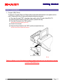
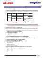
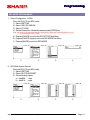
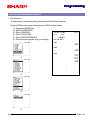
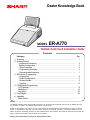
Dealer Knowledge Book
MODEL
ER-A770
Debitek Cash Card Installation Guide
Contents
Category
1. Overview ....................................................................................................................
2. Getting Started
- Equipment Connection ........................................................................................
- System Configuration .........................................................................................
- Reset Procedure ..................................................................................................
- Programming Principles .....................................................................................
- Recommended Sequence .................................................................................
3. SRV Mode Programming
- Program List .........................................................................................................
- Device Configuration ...........................................................................................
- System Presets ....................................................................................................
- Free Key ...............................................................................................................
4. PGM2 Mode Programming
- CAT2 Settings .........................................................................................................
- Media Keys ..............................................................................................................
- Auto Keys .................................................................................................................
5. Final Stages ...............................................................................................................
6. Appendix
- Quick Set Up ...........................................................................................................
Pg.
1
2
3
5
6
7
8
9
9
10
14
15
22
25
Notice:
The Debitek software and/or documentation referred to in this manual are furnished under license by Debitek and may
only be used or copied in accordance with the terms of such license.
Except as permitted by such license, no part of the software or documentation may be reproduced, stored in a retrieval
system, or transmitted, in any form or by any means, electronic, mechanical, recording, or otherwise, without the prior
written permission of Datacap Systems Inc.This software and/or documentation are furnished under license and may be
used or copied in accordance with the terms of such license.
Designs and specifications are subject to change without notice.
Intr
oduction
Introduction
TRADEMARKS
Debitek is either the trademark or registered trademark of Debitek, Inc. in the United States and/or
other countries. All other trademarks and registered marks are the property of their respective
holders.
NOTICE TO USERS
This manual is intended to assist authorized Sharp dealers, with learning and understanding how to install
and provide support in the utilization of the ER-A770 credit card authorization interface utilizing Debitek's
card reader products. This assumes that you are familiar with the general programming concepts of the
ER-A770. Please read this introductory section carefully as it will provide helpful hints and
recommendations that will make your time more efficient and produce time saving results. This manual is
not intended for end user customers of authorized Sharp dealers. Debitek is solely responsible for the
card reader product and its documentation. Any information in this manual is subject to any instructions or
information in Datacap's documentation.
Designs and specifications are subject to change without notice.
preface / i
Ov
er vie
w
Over
view
OVERVIEW
The ER-A770 model POS terminals provide an interface for supporting the Debitek Card Reader unit.
The primary configuration depicts that every POS terminal within the system will be connected to a card
reader.
1. Types of Configurations:
1) Standalone
2) In Line
2. Key functions provided by the ER-A770:
1) Full payment
2) Partial payment
3) Cash Card Ejection
Designs and specifications are subject to change without notice.
Page / 1
Getting Star
ted
Started
EQUIPMENT CONNECTION
1. The ER-A770 Cash Card Connection:
The ER-A770 provides two RS-232 communication ports standard with the possibility of adding
the ER-A7RS optional RS-232 expansion board to increase the number of RS-232 ports to four
maximum. The instructions provided within will be based on the standard configuration.
Connection for the Cash Card Reader may be attached to the ER-A770 as shown below in
(Fig. 1 and Fig. 2):
When using the CAT/EFT function, the connection
for the cable may be
port-1 (CH-1) or port-2 (CH-2)
(FIG.1)
(FIG.2)
Note:
The extension cable for connection is provided with the Card Reader. For the specific pin outs, please call Debitek
Customer Service.
Designs and specifications are subject to change without notice.
Page / 2
Getting Star
ted
Started
2. System Configuration:
1) Block Diagram:
(SRN Network)
Debitek
Card Reader
SHARP
ER-01PU
Debitek
Card Reader
ER-A770
ER-A770
SHARP
ER-03DW
SHARP
ER-03DW
(FIG.3)
2) Equipment List:
EQU IPMEN T LIST
Provider
SH AR P
Standalone C onfig.
Model/Part N o.
Qty
POS termi nal
ER-A770
1
C ash D rawer
ER-03D W
1
Memory Opti on
UP-P02MB2
* as requi red
* as requi red
--
2 Sta. Thermal Pri nter
ER-01PU
1
KD C T-C R-SHARPER
1
L o cal
Procurement D ebi tek C ard Reader
* Connection cablesare included
Note: For InLine configurations as shown in (Fig. 3), each POS terminal will have a Cash Card Reader connected.
Designs and specifications are subject to change without notice.
Page / 3
Getting Star
ted
Started
3) Debitek Accessory Items:
Debitek Order Number
Description
KHAR-DCT-PC-9
DOC-201001
KDCS-3-64
KCRD-PCC-CT
KAYS-CT3-E
- (9 to 25) SHARP-to-Debitek connection cable
- Set up document for the card reader
- Data Collector/Programming device ***
- Cleaning cards
- Spare Card Reader mechanism
*** Dealers who are placing their order for the very 1st time will not have this device.
The Data Collector/Programming device is essential for setting up the Debitek Card
Reader System.
For further assistance, please contact your Debitek representative or contact Debitek
directly by calling:
( 423 ) 894 - 6177
Designs and specifications are subject to change without notice.
Page / 4
Getting Star
ted
Started
RESET PROCEDURES
1. Program (SRV) Reset:
To perform a Program Reset, the Reset switch located beneath the back cover panel must be
used. Please refer to (fig. 4) when performing the below key sequence.
(1) Turn the AC power "OFF" using the power switch on the RH-side of the ER-A770.
(2) Place the Reset Switch to the "ON" position (towards the rear).
(3) Turn the AC power to the "ON" position.
(Please note that the display goes out)
(4) Count for 5 seconds.
(5) Place the Reset Switch to the "OFF" position (towards the front)
(Please note that the display becomes lit.
(FIG.4)
Failure to adhere to one of the above procedures when instructed to do so may result in corrupt
or broken RAM addressing
Designs and specifications are subject to change without notice.
Page / 5
Getting Star
ted
Started
PROGRAMMING PRINCIPLES
1. Introduction:
The ER-A770 POS terminal may be interfaced with peripheral devices such as card readers
as a method of sales transaction finalization. The different types of function and media keys to
be included for the system setup are recommended below.
Please review this section carefully as it provides the recommended settings for the different
methods for finalization sales transactions.
2. Programming Principles:
The ER-A770 incorporates the use of a programming keyboard sheet which is fixed
while in SRV and PGM2 modes. While in these modes, there are certain keys that are used to
make programming the ER-A770 easier to accomplish.
Please review the below list of function keys available while programming;
FUNCTION
$
!
"
#
DESCRIPTION
The UP, DOWN, LEFT and RIGHT arrow keys are used to navigate within the specified menu and/
or preset entry field.
PAGE
UP
Used to scroll the programming window back to the previous page.
PAGE
DOWN
Used to scroll the programming window to the next page.
.
SBTL
Used to "toggle" between fixed selections within a preset entry field when it is applicable.
Used to "list" available fixed selections within a preset entry field when it is applicable.
ENTER
Used to "set" each preset entry field.
CA/AT
Used to "finalize" each preset entry field.
CL
CANCEL
Used to clear the last setting you have programmed or clear an error state.
Used to "cancel" programming and to return to the previous screen.
Designs and specifications are subject to change without notice.
Page / 6
Getting Star
ted
Started
RECOMMENDED SEQUENCE FOR PROGRAMMING
1. Prior to Programming:
1) Always install the necessary options (i.e. Optional RAM, etc.) prior to programming.
2) Insure that the ER-A770 is installed with the proper ROM version using the chart below:
Model
R OM#
ROM #1
D escription
D ate
770_1.ROM
L ab el
RAJ1A
05/2000
ROM #2
770_2.ROM
ROM #1
770_1B.ROM
RAK1A
ER-A770
RAJ1B
06/2001
ROM #2
770_2B.ROM
RAK1B
Note: The Debitek Cash Card will work with either version ROM object.
3) Start your programming sessions by executing one of the Master Reset operations.
(for detailed information about the Master Reset operations, please refer to the applicable Service Manual)
2. Recommended Sequence for programming:
Please complete the SRV-mode and PGM-mode sections in the order outlined below:
1) Always back up your existing program with the 02FD.EXE Utility prior to adding the
programming for the Cash Card Reader.
2) Set the Device Configuration:
(a) CAT#2 or
(b) CAT#3
3) Set any applicable System Presets (SRV job #900 series).
4) Place the necessary Function keys on the keyboard (SRV job#950 Free Key).
5) Allocate any Memory Files (SRV job#970 series).
6) Perform a Program Reset (SRV Reset).
7) Set related presets in PGM2 mode.
(a) CAT Settings
(b) Media Key presets
(c) AUTO key programming
8) Remove unwanted function keys leaving the [AUTO] keys in place.
9) Conduct a Test with each of the finalization keys.
(a) Debit
(b) Partial Debit
(c) Eject Card
Designs and specifications are subject to change without notice.
Page / 7
Pr
o g r amming
Pro
PROGRAM LIST
1. SRV Mode Related Jobs:
The below table represents the SRV mode jobs related to the Cash Card interface.
SRV Mode Related Jobs
1. Device Assign
CAT#2
Channel No. settings
CAT#3
Channel No. settings
2. JOB#900 System Presets
Jo b #
Bit
Description
Data
Printing of Dept./PLU Codes Yes/No
906
A
4/0
Entry which makes the PLU Stock Counter go Negative
Inhibit/Allow with Error Indication/Allow unconditionally
916
2/1/0
Finalization by Charge Media when SBTL is <= 0 Yes/No
4/0
----
---
----
---
B
3. JOB#950 Free Key
Func.#
Description
084
Auto key
085
Auto2 key
086
Auto3 key
114
Charge1 key
115
Charge2 key
117
Charge4 key
2. PGM2 Mode Related Jobs:
The below table represents the PGM2 mode jobs related to the Cash Card interface.
PGM2 Mode R elated Jobs
1. C AT Setting
Jo b #
C AT
PR ESET
#2
D escription
MR S D efault
R ecommended
Ti me Out1
010
005
Ti me Out2
099
010
Baud Rate
9600bps
9600bps
Product C ode
00000000
00000000
Preset
2. Media Settings
Jo b #
C harge
D escription
D ata
C H1
for full D ebi t
see detai l s for sel ected param eters
C H2
for parti al D ebi t
see detai l s for sel ected param eters
C H4
for C ard Ejecti on
see detai l s for sel ected param eters
Designs and specifications are subject to change without notice.
Page / 8
Pr
o g r amming
Pro
SRV MODE PROGRAMMING
1. Device Configuration - CAT#2:
Place the ER-A770 into SRV mode:
1) Select 2 SETTING
2) Select 1 DEVICE ASSIGN
3) Select 15 CAT#2
4) Set the Channel No. followed by depressing the [ENTER] key.
Note: the RS-232 port which the Debitek Card Reader is physically connected (Refer to pg. 2).
*** for this example CH#1 is used.
5) Depress [CANCEL] to exit to the SRV SETTING Sub-Menu.
6) Depress [CANCEL] again to exit to the SRV MODE Sub-Menu.
7) Depress [MODE] to exit to the REG MODE.
1
2
3
4
3
4
2. SRV Mode System Presets:
Place the ER-A770 into SRV mode;
1) Select 2 SETTING
2) Select 2 SYSTEM PRESET
3) Set the following values;
a) Job#906:
b) Job#916:
1
= 0xxx
= x4xx
2
Designs and specifications are subject to change without notice.
Page / 9
Pr
o g r amming
Pro
3. Free Key Layout:
The Function keys required and the description for recommended usage are shown below:
FUNCTION
DESCRIPTION
AUTO
The AUTO key is preset for the Debit settlement key using CH1.
AUTO2
The AUTO2 key is preset for the Partial Debit settlement key using CH2.
AUTO3
The AUTO3 key is preset for the Card Ejection function using CH4.
CH1
The CH1 key will be programmed for full Debit settlement which initiates the Card Reader.
CH2
The CH2 key will be programmed for partial Debit settlement enforcing an amount entry which
initiates the Card Reader.
CH4
The CH4 key will be programmed to initiate the Card Reader to "EJECT" the card once
depressed.
RFND
The RFND key will be used when an error in entry has been made and will allow the amount to
be restored onto the Cash Card.
Note: It is highly recommended that you place the usage of the REFUND key under Manager's control. For
further details on how to incorporate Manager's control, please refer to the applicable Instruction Manual
for Manager code and Optional presetting.
Note: It is important to note that "ONLY" the specified Charge media keys may be used.
Designs and specifications are subject to change without notice.
Page / 10
Pr
o g r amming
Pro
SRV MODE PROGRAMMING READOUT
1. System Presets:
To obtain the System preset reading, please follow the below key sequence:
Place the SRV key in the SRV mode:
1) Select 1 READING
2) Select 1 SYSTEM PRESETS
3) Select 2 REPORT PRINTER
4) Once the report is printed, verify your settings.
YOUR RECEIPT
THANK YOU
10/01/2001
#0133
7:45PM
000001
SYSTEM PRESETS
1
2
3
0002
0000
4000
0000
0005
0030
0010
0000
2000
0024
0000
0061
0104
1100
0040
1400
0000
2233
5100
2040
0004
0000
0010
1433
0303
0000
0000
0060
0000
0000
4000
901#
902#
903#
904#
905#
906#
907#
908#
909#
910#
911#
912#
913#
914#
915#
916#
917#
918#
919#
920#
921#
922#
923#
924#
925#
926#
927#
928#
929#
980#
981#
Z REPORT COUNTER
TRANSACTION Z1
TRANSACTION Z2
0000
0000
0000
:
:
POSITIVE GT
GT2
NEGATIVE GT
GT3
TRAINING GT
TR
$00000000000.00
$00000000000.00
$00000000000.00
:
:
AUTO KEY PGM
REG MODE
START UP
Designs and specifications are subject to change without notice.
0000
0000
0000
Page / 11
Pr
o g r amming
Pro
2. Device Configuration:
To obtain the Device Assignment preset reading, please follow the below key sequence:
Place the SRV key in the SRV mode:
1) Select 1 READING
2) Select 2 DEVICE ASSIGN
3) Select 2 REPORT PRINTER
4) Once the report is printed, verify your settings.
YOUR RECEIPT
THANK YOU
10/01/2001
#0134
7:46PM
000001
DEVICE CONFIG
J PRINTER
R PRINTER
BILL PRINTER
REPORT PRINTER
1
2
KP#1
KP#2
KP#3
KP#4
KP#5
KP#6
KP#7
KP#8
KP#9
CAT#1
CAT#2
CAT#3
SCALE
COIN DISP.
ONLINE
CVM DATA I/F
------T#000-C#2
YES
EPSON TM-U200
ONE SHEET
--------------------C#1
-----------
3
Designs and specifications are subject to change without notice.
Page / 12
Pr
o g r amming
Pro
3. Free Key Layout:
To obtain the Free Key Layout preset reading, please follow the below key sequence:
Place the SRV key in the SRV mode:
1) Select 1 READING
2) Select 6 FREE KEY LAYOUT
3) Select 2 REPORT PRINTER
4) Once the report is printed, verify your settings.
YOUR RECEIPT
THANK YOU
10/01/2001
#0135
7:47PM
000001
FREE KEY LAYOUT
1
001
002
003
004
005
006
007
008
009
010
011
012
013
014
015
060
061
062
2
084
085
086
114
115
116
117
3
Designs and specifications are subject to change without notice.
231
232
233
0
KEY
1
KEY
2
KEY
3
KEY
4
KEY
5
KEY
6
KEY
7
KEY
8
KEY
9
KEY
00 KEY
000 KEY
.
KEY
CL
@/FOR
:
:
I.VOID
ST VD
RFND
:
:
AUTO
AUTO2
AUTO3
:
:
CH1
CH2
CH3
CH4
:
:
PMEN48
PMEN49
PMEN50
109
110
122
134
111
123
135
112
124
136
121
--133
137
125
114
126
141
150
149
148
153
152
--151
-------
Page / 13
Pr
o g r amming
Pro
PGM2 MODE PROGRAMMING
1. CAT SETTINGS:
Entering the PGM2 mode may be achieved from the REG mode as follows:
1)
2)
3)
4)
5)
Depress the [MODE] key
Select 9 PGM2 MODE
Select 13 CAT SETTING
Select 2 CAT2
Set the following values;
TIMEOUT TIME1
TIMEOUT TIME2
BAUD RATE
PRODUCT CODE
= 005
= 010
= 9600 bps
= 0000000000
6) Depress the [CA/AT] key when all settings are completed to exit to the CAT SETTING
Sub-Menu.
7) Depress the [CANCEL] key to exit to the PGM2 Sub-Menu.
1
2
Designs and specifications are subject to change without notice.
3
4
Page / 14
Pr
o g r amming
Pro
PROGRAMMING MEDIA KEYS
There are 3 different functions used in the Debitek Cash Card implementation. The functions are 1) Debit,
2) Partial Debit and 3) Eject. The specific Charge Media key is significant to the interface and
should be preset exactly as indicated on the following pages.
IMPORTANT: Only the specified Charge media keys may be used for the Cash Card interface !!!
1. Debit Finalization Key:
Entering the PGM2 mode may be achieved from the REG mode as follows:
1)
2)
3)
4)
5)
6)
7)
Depress the [MODE] key
Select 9 PGM2 MODE
Select 2 SETTING
Select 5 MEDIA
Select 3 CHARGE
Select 1 CHARGE1
Set the following related CH1 Media key's presets;
CH1 Media Key
Related - Parameter Field Setting
Recommended
Setting
Preset
Text (Gross)
CHARGE1
DEBIT
Text (Refund)
CHARGE1-
DEBIT-
Short Tender
Enable/Disable
Disable
CAT Operation
NON-COMPULSORY
CAT2 COMPULSORY
CAT2 Action Code
CHG-SALE
CHG-SALE
CAT2 Trans. Type
CH1
CH1
Card# Prt
Yes/No
No
Sign.Line Prt.
Yes/No
No
Card Holder Prt.
Yes/No
No
Expiration Prt.
Yes/No
No
Number of Rcpt
1-9
1
Change Due
Enable/Disable
Disable
Drawer Opening
Yes/No
No
Amount Entry
Inhibit/Compulsory
Inhibit
8) Depress [CA/AT] when all settings are completed to exit to the PGM2 Charge Sub-Menu.
9) Depress [CANCEL] to exit the Charge Sub-Menu and return to the Media preset menu.
Designs and specifications are subject to change without notice.
Page / 15
Pr
o g r amming
Pro
1
2
3
4
5
6
7
8
9
10
11
12
13
14
Designs and specifications are subject to change without notice.
Page / 16
Pr
o g r amming
Pro
2. Partial Debit Finalization Key:
Entering the PGM2 mode may be achieved from the REG mode as follows;
1)
2)
3)
4)
5)
6)
7)
Depress the [MODE] key
Select 9 PGM2 MODE
Select 2 SETTING
Select 5 MEDIA
Select 3 CHARGE
Select 2 CHARGE2
Set the following related CH2 Media key's presets:
CH2 Media Key
Related - Parameter Field Setting
Recommended
Setting
Preset
Text (Gross)
CHARGE2
PARTIAL
Text (Refund)
CHARGE2-
PARTIAL-
Short Tender
Enable/Disable
Enable
CAT Operation
NON-COMPULSORY
CAT2 COMPULSORY
CAT2 Action Code
CHG-SALE
CHG-SALE
CAT2 Trans. Type
CH2
CH2
Card# Prt
Yes/No
No
Sign.Line Prt.
Yes/No
No
Card Holder Prt.
Yes/No
No
Expiration Prt.
Yes/No
No
Number of Rcpt
1-9
1
Change Due
Enable/Disable
Disable
Drawer Opening
Yes/No
No
Amount Entry
Inhibit/Compulsory
Compulsory
8) Depress [CA/AT] when all settings are completed to exit to the PGM2 Charge Sub-Menu.
9) Depress [CANCEL] to exit the Charge Sub-Menu and return to the Media preset menu.
Designs and specifications are subject to change without notice.
Page / 17
Pr
o g r amming
Pro
1
2
3
4
5
6
7
8
9
10
11
12
13
14
Designs and specifications are subject to change without notice.
Page / 18
Pr
o g r amming
Pro
3. Card Ejection Key:
Entering the PGM2 mode may be achieved from the REG mode as follows;
1)
2)
3)
4)
5)
6)
7)
Depress the [MODE] key
Select 9 PGM2 MODE
Select 2 SETTING
Select 5 MEDIA
Select 3 CHARGE
Select 4 CHARGE4
Set the following related CH4 Media key's presets:
CH2 Media Key
Related - Parameter Field Setting
Recommended
Setting
Preset
Text (Gross)
CHARGE4
E JE C T
Text (Refund)
CHARGE4-
EJECT-
Short Tender
Enable/Disable
Disable
CAT Operation
NON-COMPULSORY
CAT2 COMPULSORY
CAT2 Action Code
CHG-SALE
CHG-SALE
CAT2 Trans. Type
CH4
CH4
Card# Prt
Yes/No
No
Sign.Line Prt.
Yes/No
No
Card Holder Prt.
Yes/No
No
Expiration Prt.
Yes/No
No
Number of Rcpt
1-9
1
Change Due
Enable/Disable
Disable
Drawer Opening
Yes/No
No
Amount Entry
Inhibit/Compulsory
Inhibit
8) Depress [CA/AT] when all settings are completed to exit to the PGM2 Charge Sub-Menu.
9) Depress [CANCEL] to exit the Charge Sub-Menu and return to the Media preset menu.
Designs and specifications are subject to change without notice.
Page / 19
Pr
o g r amming
Pro
1
2
3
4
5
6
7
8
9
10
11
12
13
Designs and specifications are subject to change without notice.
Page / 20
Pr
o g r amming
Pro
MEDIA KEY PROGRAMMING READOUT
1. Key Sequence:
To obtain the media key preset reading, please follow the below key sequence:
Entering the PGM2 mode may be achieved from the REG mode as follows:
1)
2)
3)
4)
5)
6)
Depress the [MODE] key
Select 9 PGM2 MODE
Select 1 READING
Select 11 MEDIA
Select 2 REPORT PRINTER
Once the report is printed, verify your settings.
#0137
7:45PM
*PGM2*
MEDIA
CASH
CASH2
CHECK1
1
000001
10/01/2001
DEBIT
DEBITPARTIAL
PARTIAL-
EJECT
EJECT-
2
KP0000 L18
00000000000000
CA1 CA1 0000000001
KP0000 L18
00000000000000
CA2 CA2 0000000001
KP0000 L18
000000000000000
CK1 CK1 0000000001
:
:
KP0000 L18
010000001000010
CH1 CH1 2000101111
KP0000 L18
000000001000001
CH2 CH2 2000101111
:
:
KP0000 L18
010000001000010
CH4 CH4 2000101111
:
:
****CID
CHK/CG
9999999.99
999999.99
3
4
Designs and specifications are subject to change without notice.
Page / 21
Pr
o g r amming
Pro
PROGRAMMING AUTO KEYS
Because the Cash Card is utilizing the credit card authorization interface, it is necessary to utilize the
AUTO Sequence function keys to automatically depress the [ENTER] key when the "SWIPE CARD"
prompt appears in the display.
1. AUTO key - Debit Finalization Key:
Entering PGM2 mode may be achieved from the REG mode as follows:
1)
2)
3)
4)
5)
6)
7)
Depress the [MODE] key
Select 10 AUTO KEY MODE
Depress the [AUTO] key
Depress the [CH1] key
Depress the [ENTER] key
Depress the [AUTO] key
Depressing the [CANCEL] key will return the ER-A770 to the REG-mode
1
2
3
2. AUTO key - Partial Debit Finalization Key:
Entering PGM2 mode may be achieved from the REG mode as follows:
1)
2)
3)
4)
5)
6)
7)
Depress the [MODE] key
Select 10 AUTO KEY MODE
Depress the [AUTO2] key
Depress the [CH2] key
Depress the [ENTER] key
Depress the [AUTO2] key
Depressing the [CANCEL] key will return the ER-A770 to the REG-mode
1
2
Designs and specifications are subject to change without notice.
3
Page / 22
Pr
o g r amming
Pro
3. AUTO key - Eject Card Key:
Prior to creating this Auto key for ejecting the card, it is necessary to also create a zero-priced PLU
which will become part of the Auto sequence entry to the Charge-4 media key.
In this case, it is assumed that the PLU code 999 has been previously set as a zero-priced PLU.
Entering the PGM2 mode may be achieved from the REG mode as follows:
1)
2)
3)
4)
5)
6)
5)
6)
7)
Depress the [MODE] key
Select 10 AUTO KEY MODE
Depress the [AUTO3] key
Enter the PLU code "999"
Depress the [PLU/SB] key
Depress the [CH4] key
Depress the [ENTER] key
Depress the [AUTO3] key
Depressing the [CANCEL] key will return the ER-A770 to the REG-mode
1
2
Designs and specifications are subject to change without notice.
3
Page / 23
Pr
o g r amming
Pro
AUTO KEY PROGRAMMING READOUT
1. Key Sequence:
To obtain the Auto key preset reading, please follow the below key sequence:
Entering PGM2 mode may be achieved from the REG mode as follows:
1)
2)
3)
4)
5)
6)
Depress the [MODE] key
Select 9 PGM2 MODE
Select 1 READING
Select 25 AUTO KEY
Select 2 REPORT PRINTER
Once the report is printed, verify your settings.
000001
10/01/2001
#0138
7:52PM
*PGM2*
AUTO KEY
#01
CH1
ENTER
#02
CH2
ENTER
#03
9 KEY
9 KEY
9 KEY
PLU/SB
CH4
ENTER
1
:
:
:
2
3
4
Designs and specifications are subject to change without notice.
Page / 24
Pr
o g r amming
Pro
FINAL STAGES
During SRV-mode programming the [CH1], [CH2] and [CH4] keys were placed directly onto the keyboard
to be accessed during the Auto key presetting. Now that the Auto keys have been preset, it is
recommended that the above mentioned function keys be removed from the keyboard assignment.
Place the ER-A770 into SRV mode:
1) Select 2. SETTING
2) Select 6. FREE KEY
3) Select 114. CH1
4) Depress the [@/FOR] key to remove the [CH1] key.
5) Select 115. CH2
6) Depress the [@/FOR] key to remove the [CH2] key.
7) Select 117. CH4
8) Depress the [@/FOR] key to remove the [CH4] key.
9) Depress the [CA/AT] when all settings are completed to return to the SETTING Main-Menu.
10) Depress the [MODE] key to return the REG-mode.
1
2
3
4
5
Notes:
1.When selecting the [CH1], [CH2] and [CH4] function keys during SRV Job #950, use the [UP] and [DOWN] arrow
keys.
2.When the [@/FOR] key is depressed to remove the highlighted function key, the ER-A770 will automatically highlight
the next function key.
Designs and specifications are subject to change without notice.
Page / 25
A ppendix
QUICK SET UP
The following table will show the summarized quick set up procedure for the ER-A770. It is assumed
that the Debitek Card Reader has been received with the correct ECR parameters loaded.
EC R
Mode
N o.
Action
1
Install all Options (ROM/RAM, etc.)
2
Connect all Peripherals (i.e. Debitek, etc.)
Related Preset
Off
3
SRV
PGM2
SRV
Master Reset
*** M RS-1 is described for this exam ple
MRS-1: AC Power to "OFF", place the
RESET switch to the "ON" position,
AC power to "ON", place the RESET
switch to the "OFF" position while
depressing [RECEIPT] feed key, enter
the PASSWORD.
4
Set Device Assign
2 SETTING, 1 DEVICE ASSIGN,
15 CAT#2, enter CH#. (0-7)
5
Set System Presets
2 SETTING, 2 SYSTEM PRESETS,
JOB#906 = 0xxx, JOB#916 = x4xx
6
Set Free Key Layout
2 SETTING, 6 FREE KEY,
FUNC#084, 085, 086, 114, 115 and
117
7
Set CAT#2 presets
15 CAT SETTING, 2 CAT2, preset
TIME OUT1 and TIME OUT2
8
Set Media Key presets
2 SETTING, 5 MEDIA, 3 CHARGE, 1
CHARGE1, 2 CHARGE2 and
4 CHARGE4
9
Set Auto Key presets
Auto = CH1, ENTER
Auto2 = CH2, ENTER
Auto3 = 999, PLU/SB, CH4, ENTER
10
Remove unwanted function keys - Free Key
2 SETTING, 6 FREE KEY,
FUNC#114, 115 and 117
Designs and specifications are subject to change without notice.
Appendix / 1
COPYRIGHT© 2001 BY SHARP ELECTRONICS CORPORATION
All rights reserved.
Printed in U.S.A.
No part of this publication may be reproduced,
stored in a retrieval system, or transmitted.
In any form or by any means,
electronic, mechanical, photocopying, recording, or otherwise,
without prior written permission of the publisher.