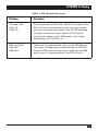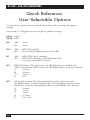
1
IC108A
IC108C
IC108AE
APRIL 2002
IC109A
IC109A-R2
IC109C
IC109AE
RS-232↔485/422 Converter Plus
RS-232↔485/422 Opto-Isolator/Converter
232↔485/422
US
CONVERTER PL
NORMAL
S CD
RX TX RT
DCE
DTE
DLB
TX RX
CD
RTS
PWR
232↔485/422
ER
OR/CONVERT
OPTO-ISOLAT
NORMAL
DLB
CUSTOMER
SUPPORT
INFORMATION
S CD
RX TX RT
DCE
DTE
TX RX
CD
RTS
PWR
Order toll-free in the U.S.: Call 877-877-BBOX (outside U.S. call 724-746-5500)
FREE technical support 24 hours a day, 7 days a week: Call 724-746-5500 or fax 724-746-0746
Mailing address: Black Box Corporation, 1000 Park Drive, Lawrence, PA 15055-1018
Web site: www.blackbox.com • E-mail: [email protected]
FCC AND IC RFI STATEMENTS
FEDERAL COMMUNICATIONS COMMISSION
AND
INDUSTRY CANADA
RADIO FREQUENCY INTERFERENCE STATEMENTS
This equipment generates, uses, and can radiate radio-frequency energy, and if not
installed and used properly, that is, in strict accordance with the manufacturer’s
instructions, may cause interference to radio communication. It has been tested
and found to comply with the limits for a Class A computing device in accordance
with the specifications in Subpart B of Part 15 of FCC rules, which are designed to
provide reasonable protection against such interference when the equipment is
operated in a commercial environment. Operation of this equipment in a
residential area is likely to cause interference, in which case the user at his own
expense will be required to take whatever measures may be necessary to correct
the interference.
Changes or modifications not expressly approved by the party responsible
for compliance could void the user’s authority to operate the equipment.
This digital apparatus does not exceed the Class A limits for radio noise emission from
digital apparatus set out in the Radio Interference Regulation of Industry Canada.
Le présent appareil numérique n’émet pas de bruits radioélectriques dépassant les limites
applicables aux appareils numériques de la classe A prescrites dans le Règlement sur le
brouillage radioélectrique publié par Industrie Canada.
1
RS-232↔485/422 CONVERTERS
NORMAS OFICIALES MEXICANAS (NOM)
ELECTRICAL SAFETY STATEMENT
INSTRUCCIONES DE SEGURIDAD
1. Todas las instrucciones de seguridad y operación deberán ser leídas antes de
que el aparato eléctrico sea operado.
2. Las instrucciones de seguridad y operación deberán ser guardadas para
referencia futura.
3. Todas las advertencias en el aparato eléctrico y en sus instrucciones de
operación deben ser respetadas.
4. Todas las instrucciones de operación y uso deben ser seguidas.
5. El aparato eléctrico no deberá ser usado cerca del agua—por ejemplo, cerca
de la tina de baño, lavabo, sótano mojado o cerca de una alberca, etc..
6. El aparato eléctrico debe ser usado únicamente con carritos o pedestales que
sean recomendados por el fabricante.
7. El aparato eléctrico debe ser montado a la pared o al techo sólo como sea
recomendado por el fabricante.
8. Servicio—El usuario no debe intentar dar servicio al equipo eléctrico más allá
a lo descrito en las instrucciones de operación. Todo otro servicio deberá ser
referido a personal de servicio calificado.
9. El aparato eléctrico debe ser situado de tal manera que su posición no
interfiera su uso. La colocación del aparato eléctrico sobre una cama, sofá,
alfombra o superficie similar puede bloquea la ventilación, no se debe colocar
en libreros o gabinetes que impidan el flujo de aire por los orificios de
ventilación.
10. El equipo eléctrico deber ser situado fuera del alcance de fuentes de calor
como radiadores, registros de calor, estufas u otros aparatos (incluyendo
amplificadores) que producen calor.
11. El aparato eléctrico deberá ser connectado a una fuente de poder sólo del
tipo descrito en el instructivo de operación, o como se indique en el aparato.
2
NOM STATEMENT
12. Precaución debe ser tomada de tal manera que la tierra fisica y la polarización
del equipo no sea eliminada.
13. Los cables de la fuente de poder deben ser guiados de tal manera que no
sean pisados ni pellizcados por objetos colocados sobre o contra ellos,
poniendo particular atención a los contactos y receptáculos donde salen del
aparato.
14. El equipo eléctrico debe ser limpiado únicamente de acuerdo a las
recomendaciones del fabricante.
15. En caso de existir, una antena externa deberá ser localizada lejos de las lineas
de energia.
16. El cable de corriente deberá ser desconectado del cuando el equipo no sea
usado por un largo periodo de tiempo.
17. Cuidado debe ser tomado de tal manera que objectos liquidos no sean
derramados sobre la cubierta u orificios de ventilación.
18. Servicio por personal calificado deberá ser provisto cuando:
A: El cable de poder o el contacto ha sido dañado; u
B: Objectos han caído o líquido ha sido derramado dentro del aparato; o
C: El aparato ha sido expuesto a la lluvia; o
D: El aparato parece no operar normalmente o muestra un cambio en su
desempeño; o
E: El aparato ha sido tirado o su cubierta ha sido dañada.
3
RS-232↔485/422 CONVERTERS
TRADEMARKS USED IN THIS MANUAL
Any trademarks mentioned in this manual are acknowledged to be the property of the
trademark owners.
4
CONTENTS
Contents
Chapter
Page
1.
Specifications . . . . . . . . . . . . . . . . . . . . . . . . . . . . . . . . . . . . . . . . . . . . . . . . . . 6
2.
Introduction . . . . . . . . . . . . . . . . . . . . . . . . . . . . . . . . . . . . . . . . . . . . . . . . . . . 8
3.
Installation . . . . . . . . . . . . . . . . . . . . . . . . . . . . . . . . . . . . . . . . . . . . . . . . . . . . 9
3.1 Jumper and Switch Configuration . . . . . . . . . . . . . . . . . . . . . . . . . . . . . 9
3.1.1 DTE/DCE Configuration . . . . . . . . . . . . . . . . . . . . . . . . . . . . . . 9
3.1.2 Frame Ground/Signal Ground. . . . . . . . . . . . . . . . . . . . . . . . . . 9
3.1.3 Half/Full-Duplex Operation . . . . . . . . . . . . . . . . . . . . . . . . . . . . 9
3.1.4 CTS Delay . . . . . . . . . . . . . . . . . . . . . . . . . . . . . . . . . . . . . . . . . . 11
3.1.5 RS-485 Driver Enable . . . . . . . . . . . . . . . . . . . . . . . . . . . . . . . . . 11
3.1.6 Half-Duplex Turnaround Delay . . . . . . . . . . . . . . . . . . . . . . . . 12
3.1.7 RS-485 Interface Terminated or Unterminated . . . . . . . . . . . 12
3.1.8 Normal/Loopback Operation . . . . . . . . . . . . . . . . . . . . . . . . . 13
3.1.9 RS-485 Interface Line Biased (Fail-Safe) . . . . . . . . . . . . . . . . . 13
3.2 DCE Configuration/DTE Configuration . . . . . . . . . . . . . . . . . . . . . . . 14
3.3 Typical Applications . . . . . . . . . . . . . . . . . . . . . . . . . . . . . . . . . . . . . . . . 22
Appendix A: Pinning . . . . . . . . . . . . . . . . . . . . . . . . . . . . . . . . . . . . . . . . . . . . . . 28
Quick Reference: User-Selectable Options . . . . . . . . . . . . . . . . . . . . . . . . . . . . . 30
5
RS-232↔485/422 CONVERTERS
1. Specifications
Optical Isolation: IC109A, IC109AE, IC109C only
Interface: (1) asynchronous RS-232 port (DTE/DCE selectable); (1) asynchronous
RS-485 port with improved surge protection and switch-selectable line termination
or line bias
Connectors: (1) DB25 female RS-232 port; (1) four-wire terminal block (TB1)
RS-485 port
Pins Supported: RS-232 port: TD, RD, RTS, CTS, CD, DTR, DSR, SG, and FG;
RS-485 port: TXA, TXB, RXA, RXB
Data Rate: Up to 115 kbps, transparent to data
Indicators: (5) LEDs: TX, RX, RTS, CD, and PWR
Temperature Tolerance: Operating: 32 to 122°F (0 to 50°C); Storage: -4 to +158°F
(-20 to +70°C)
Humidity: 0 to 95% relative humidity, noncondensing
MTBF: Approximately 180,000 hours (ground benign environment)
Power: PS154 (for use with IC108A, IC109A): Input: 120 V, 60 Hz, 20W; Output: AC
17VCT, 0.7A; PS154E (for use with IC108AE, IC109AE): Input: 230 V, 50 Hz, 20W;
Output: AC 17VCT, 750 mA
Size: Standalone Unit: 1.8"H x 5.5"W x 8.5"D (4.6 x 14 x 21.6 cm);
Rackmount Card: 7.4"L x 4.7"W (18.8 x 11.9 cm); 0.6 inches thick (1.6 cm)
Weight: Standalone Unit: 1 lb. (0.5 kg); Power supply only: PS154: 0.4 lb. (0.2 kg),
PS154E: 1.1 lb. (0.5 kg)
Operation: Point to Point or Multipoint; Half or Full Duplex; Transparent to data;
Selectable RTS-to-CTS delay with option to inhibit CTS if CD is present (DCE);
DTE or DCE configurable RS-232 port; Normal or loopback operation
Timeout Delay: 0.15, 0.7, 2, 7, or 70 msec (for the RS-485 driver enabled by data
feature)
6
CHAPTER 1: Specifications
Typical Speed Versus Distance (4-wire point-to-point 26-AWG twisted pair):
Speed
Distance
1200 bps
2400 bps
4800 bps
9600 bps
19,200 bps
38,400 bps
64,000 bps
115 kbps
4 miles (6.4 km)
3 miles (4.8 km)
2.3 miles (3.7 km)
1.7 miles (2.7 km)
1.2 miles (1.9 km)
0.9 mile (1.4 km)
0.75 mile (1.2 km)
0.4 mile (0.6 km)
NOTE
Speed and distances will depend on actual operating conditions.
7
RS-232↔485/422 CONVERTERS
2. Introduction
The RS-232↔485/422 Converter Plus is an RS-232-to-RS-485 interface converter
that operates in the same manner as a line driver. It allows an RS-232 device to
transmit data over much longer distances than is normally possible (up to
4 miles—6.4 km—at 1200 bps). The advantage of the RS-232↔485/422 Converter
Plus over other line drivers is that it can also operate in multipoint applications.
Depending on the operating environment, as many as 64 devices can be linked
together using twisted-pair cable.
The opto-isolating models (IC109A, IC109AE, IC109C) protect one segment of
your extended network from problems that arise on the other. Inside the
RS-232↔485/422 Opto-Isolator/Converter, optical isolation circuitry converts
electrical signals to light and back again, to keep signal noise and ground loops
from crossing between segments of your RS-485 installation. That means the
electrical noise from your factory floor won’t affect your office communications,
and the difference in ground potential between buildings won’t damage your
sensitive equipment.
Additional features include a manual loopback test to check the system wiring for
both the RS-232 and RS-485 interfaces, and transient protection on the RS-485
interface to help prevent damage due to voltage transients on the data line.
Although designed specifically to connect to other RS-232↔485/422 Converters,
the RS-485 port may be connected to any device with an RS-422 or RS-485
interface, thus acting as an interface converter. For example, this would be useful
in an industrial application where RS-485 or RS-422 devices would be connected to
an RS-232↔485/422 Converter.
The RS-232↔485/422 Converter is available in standalone and rackmount
versions. The rackmount cards (part numbers IC108C and IC109C) are designed
to be installed in the multi-function rack (part number RM005).
If you ordered the IC109A-R2, you should have received a cable and an adapter
with your RS-232↔485/422 Converter Plus. The cable is designed to plug into an
IBM PC AT (or clone) DB9 com port. The adapter is designed to be used with the
supplied cable to connect to an IBM PC computer’s DB25 com port.
8
CHAPTER 3: Installation
3. Installation
This section describes the jumper and switch functions for configuring the
RS-232↔485/422 Converter. See Figure 1 on the next page for the component
locations.
To install your RS-232↔485/422 Converter:
1. Set each of the ten jumpers/switches for your application.
2. Connect the RS-232↔485/422 Converter devices together as shown in
Figures 5 through 8 (pages 23–25).
3. Apply power. (PS154 or PS154E, depending on which RS-232↔485/422
Converter you have. See Chapter 1 for more information.)
3.1 Jumper and Switch Configuration
NOTE
As you read this section, refer to Tables 1 and 2. Table 1 (page 15) lists
DCE jumper settings, and Table 2 (page 20) lists DTE jumper settings.
3.1.1 DTE/DCE CONFIGURATION
A DIP shunt is used to select DTE or DCE configuration. For the RS-232↔485/422
Converter to appear as a DTE device, put the DIP shunt jumper in socket XW1B.
For the RS-232↔485/422 Converter to appear as a DCE device, put the DIP shunt
jumper in socket XW1A.
3.1.2 FRAME GROUND/SIGNAL GROUND
Jumper W7 ties signal ground to frame ground. The position is left open at the
factory. If signal ground is to be connected to frame ground, solder a 100-ohm,
1/2-watt resistor in location W7. A wire jumper may also be used. Care must be
taken to ensure that ground circulating currents are limited to acceptable levels.
3.1.3 HALF/FULL-DUPLEX OPERATION
Jumper W8 selects half-duplex or full-duplex operation. Set W8 to the HALF
position (B-C position) for half-duplex operation. Set W8 to the FULL position
(A-B position) for full-duplex operation.
9
RS-232↔485/422 CONVERTERS
NOTE
When the jumper W9 (CTS) is in the ON position and jumper W15 is in
the A-B position, the RS-485 driver is always turned on to enable
transmission of data. Therefore, half-duplex transmission cannot be
performed. See Section 3.1.5 for an explanation of the RS-485 driver.
Figure 1. Layout of the Printed Circuit Board.
10
CHAPTER 3: Installation
3.1.4 CTS DELAY (W9 JUMPER)
When the transmitter of a device is first turned on, an unstable carrier signal is
transmitted for several milliseconds. If data was sent during this period, it would be
received as distorted information. Setting a CTS delay on the RS-232↔485/422
Converter allows the communications link to settle down before data can be sent.
RS-232↔485/422 Converter as DCE (XW1A 8-Position Shunt)
When the RS-232↔485/422 Converter is configured as a DCE device (DIP shunt
in position XW1A), jumper W9 controls the amount of delay from the time RTS
(jumper W5 in the A-B position) is received true until CTS is asserted true. If W5 is
in the B-C position, CTS will be inhibited if an RS-485 carrier is present when RTS
is raised. To select a CTS delay period, set jumper W9 to the 0-, 10-, or 30-msec
position. Regardless of the delay setting selected, when RTS goes false, CTS will
immediately go false. If jumper W9 is in the “ON” position, CTS will follow RTS.
RS-232↔485/422 Converter as DTE (XW1B 8-Position Shunt)
When the RS-232↔485/422 Converter is configured as a DTE device (DIP shunt in
position XW1B), CTS is not supported.
3.1.5 RS-485 DRIVER ENABLE (W15)
The RS-232↔485/422 Converter’s RS-485 driver can be set to be enabled one of
three ways: by RS-232 control signals, by data, or constantly on via W9 set in the
ON position).
Driver Enabled by RS-232 Control Leads
If your equipment raises CD or RTS when it is ready to send data, you can set the
RS-485 driver to be enabled by one of these leads. If your equipment does not have
the capability to raise CD or RTS, you will need to set the RS-485 driver to be
enabled by data or constantly enabled.
In order for an RS-232 control lead to enable the RS-485 driver, W15 must be in
position A-B and W9 must be set for 0, 10, or 30 ms.
• When the RS-232 port is selected as DTE (DIP shunt in the XW1B position),
the RS-485 driver will be enabled when CD (pin 8 of the RS-232 connector)
goes true.
• When the RS-232 port is selected as DCE (DIP shunt in the XW1A position),
RTS enables the driver.
11
RS-232↔485/422 CONVERTERS
Driver Enabled by Data
The RS-485 driver can also be enabled without requiring an RS-232 control lead to
be asserted. When jumper W15 is placed in the B-C position, the driver is enabled
when data is received on the RS-232 port of the RS-232↔485/422 Converter. As
soon as the first bit of the first character is received at the RS-232 port, the RS-485
driver is enabled and an internal timer is started. The timer begins its “time out”
on a low (0) to high (1) transition of data. When the timer times out, the RS-485
driver is disabled. Jumper W17 allows this timeout delay to be set for 0.15, 0.7, 2, 7,
or 70 msec.
NOTE
There is a limitation to using this “DATA ENABLES DRIVER” feature. At
data rates above 64 Kbps, the first character in the data stream will be
garbled by the Converter. If higher data rates are required, transmit a
<break> if possible, or a <nul> character before each message. This will
enable the RS-485 driver, activate the timer, and allow the message to
be transmitted without errors. The receiving device will need to ignore
the first character received.
Driver Constantly Enabled (4 Wire Only)
The RS-485 driver can be constantly enabled by setting jumper W9 to the ON
position.
3.1.6 HALF-DUPLEX TURNAROUND DELAY
When operating in half-duplex mode (jumper W8 in the HALF position [B-C
position]), the RS-232↔485/422 Converter adds a small delay each time it stops
transmitting data and prepares to receive data. This delay allows the RS-485
interface and transmission line time to stabilize, thus reducing the possibility of
garbled data being received at the end of a message.
The turnaround delays are 0 (W16 in position A), 0.1 msec (W16 in position B),
1 msec (W16 in position C), 5 msec (W16 in position D), and 35 msec (W16 in
position E).
3.1.7 RS-485 INTERFACE TERMINATED OR UNTERMINATED
Some distortion on the twisted-pair line may be caused by impedance mismatch
from the different devices connected to the line. To help eliminate this type of
distortion, the RS-485 interface can be terminated with a resistor network at the
receiver input pins (RXA and RXB) via switch S2. When S2 is placed in the
“TERM” position, the resistor network is connected across the line. When S2 is
placed in the “UNTERM” position, no connection to the resistor network is made
and the line is not terminated.
12
CHAPTER 3: Installation
Point-to-Point
When only two devices are connected to the line in a point-to-point application,
each device should have the termination network connected to the line. Set switch
S2 to the “TERM” position.
Multipoint
For multipoint applications, switch S2 should be in the “UNTERM” position on all
the RS-232↔485/422 Converter devices in the network except for the two units at
the extreme opposite locations on the line. The extreme opposite devices are the
two devices that have the greatest cable length between them, which may not
necessarily be the devices that are physically located the farthest apart. These two
units should be set in the “TERM” position (see Figures 5 and 6). If any of the
other RS-232↔485/ 422 Converters were configured as “terminated,” the amount
of distortion could increase—possibly causing errors in the data being transmitted.
3.1.8 NORMAL/LOOPBACK OPERATION
The Normal/Loopback switch (S1) is a two-position pushbutton switch extending
through the front panel. The Normal position permits normal operation of the
RS-232↔485/422 Converter. The Loopback position allows data coming into the
RS-232↔485/422 Converter to be sent back out the same port. This is for testing
the connection between the RS-232↔485/422 Converter and the device attached
to each port.
Normal
When this switch is in the normal mode, data is passed through the Converter
from the RS-232 port to the RS-485 port and vice versa.
Loopback
When set to the loopback mode, any data received at the RS-485 port will be
transmitted back out the RS-485 port and any data received at the RS-232 port will
be transmitted back out the RS-232 port.
3.1.9 RS-485 INTERFACE LINE BIASED (FAIL-SAFE)
If S3 is in the Off position, there is no line bias. If S3 is in the On position, there is
line bias.
13
RS-232↔485/422 CONVERTERS
3.2 DCE/DTE Configuration
This section contains block diagrams (Figures 2 and 4) and jumper and switch
settings (Tables 1 and 2) for DCE/DTE operation. For a detailed description of
the jumpers and switches, see Section 3.1.
Figure 2. Simplified Functional Block Diagram (DCE Operation).
14
CHAPTER 3: Installation
Table 1. DCE Jumper Settings.
NOTE
For additional information on the jumper requirements, see Section 3.1.
Function
Jumper Requirements
1. Configure RS-232 port as DCE
XW1 in A position
2. Signal ground connected to frame ground
• Connected
W7 is IN (solder your own 100-ohm,
resistor in place)
1⁄2-watt
• Not connected
3. Half- or full-duplex operation
• Full duplex
• Half-duplex
4. CTS delay
• Yes
• No
W7 is OUT
W8 in FULL position (4 wire, A-B)
W8 in HALF position (2 wire, B-C)
W9 in 0-ms position
W9 in 10-ms position
W9 in 30-ms position
W9 in ON position
(no delay, CTS follows RTS)
15
RS-232↔485/422 CONVERTERS
Table 1 (continued). DCE Jumper Settings.
Function
5. Enable RS-485 driver
a. RS-485 driver enabled by
RS-232 control leads
• by RTS
W15 in A-B position and
W9 in 0-ms position
W9 in 10-ms position
W9 in 30-ms position
b. RS-485 driver enabled by data
• Disable timeout delay
W15 in B-C position and
W17 msec
A
70
B
7
C
2
D
0.7
E
0.15
c. RS-485 driver constantly enabled
W9 in ON position
6. Half-duplex turnaround delay
• 0-msec turnaround delay
16
Jumper Requirements
W8 in HALF position and
W16 in position A
• 0.1-msec turnaround delay
W16 in position B
• 1-msec turnaround delay
W16 in position C
• 5-msec turnaround delay
W16 in position D
• 35-msec turnaround delay
W16 in position E
CHAPTER 3: Installation
Table 1 (continued). DCE Jumper Settings.
Function
Jumper Requirements
7. RS-485 interface terminated
or unterminated
• Terminated
S2 in TERM position
• Unterminated
S2 in UNTERM position
8. Normal or loopback operation
• Normal mode
S1 in Normal position
• Loopback mode
S1 in Loopback position
9. RS-485 Interface Line Biased (FailSafe), Receive
S3 Off
No line bias
S3 On
Line biased
NOTE
If line bias is on, the RS-485 CD will ALWAYS be on.
17
RS-232↔485/422 CONVERTERS
Figure 3. Line Bias. S2 shows the line termination when
“Term” is selected. S3 shows line bias when “Bias” is selected.
18
CHAPTER 3: Installation
Opto-isolated barrier
in IC109 models
Figure 4. Simplified Functional Block Diagram (DTE Operation).
NOTE
The delay settings for W9 apply only to the CTS output of the
RS-232↔ 485/422 Converter. Since CTS is not used when the
RS-232↔485/422 Converter is configured as a DTE device, placing
jumper W9 in either the 0-, 10-, or 30-msec position will allow the CD
input to enable the RS-485 driver. When jumper W9 is in the ON
position, the CD input has no affect on the RS-485 driver.
19
RS-232↔485/422 CONVERTERS
Table 2. DTE Jumper Settings.
NOTE
For additional information on the jumper requirements, see Section 3.1.
Function
Jumper Requirements
1. Configure RS-232 port as DTE
XW1 in B position
2. Signal ground connected to
frame ground
• Connected
• Not connected
3. Half- or full-duplex operation
• Full duplex
• Half-duplex
4. CTS delay
5. Enable RS-485 driver
a. RS-485 driver enabled by
RS-232 lead CD
20
W7 is IN (100-ohm, 1/2-watt
resistor soldered in place)
W7 is OUT
W8 in FULL position (4 wire, A-B)
W8 in HALF position (2 wire, B-C)
CTS not supported
W15 in A-B position and
W9 in 0-ms position
W9 in 10-ms position
W9 in 30-ms position
CHAPTER 3: Installation
Table 2 (continued). DTE Jumper Settings.
Function
Jumper Requirements
b. RS-485 driver enabled by data
• Disable timeout delay
W15 in B-C position and
W17 msec
A
70
B
7
C
2
D
0.7
E
0.15
c. RS-485 driver constantly enabled
W9 in ON position
6. Half-duplex turnaround delay
• 0-msec turnaround delay
• 0.1-msec turnaround delay
• 1-msec turnaround delay
• 5-msec turnaround delay
• 35-msec turnaround delay
W8 in HALF position and
W16 in position A
W16 in position B
W16 in position C
W16 in position D
W16 in position E
7. RS-485 interface terminated
or unterminated
• Terminated
S2 in TERM position
• Unterminated
S2 in UNTERM position
8. Normal or loopback operation
a. Normal mode
S1 in Normal position
b. Loopback mode
S2 in Loopback position
21
RS-232↔485/422 CONVERTERS
Table 2 (continued). DTE Jumper Settings.
Function
Jumper Requirements
9. RS-485 Interface Line Biased (FailSafe), Receive
S3 Off
No line bias
S3 On
Line biased
NOTE
If line bias is on, the RS-485 CD will ALWAYS be on.
3.3 Typical Applications
This section describes some typical applications where the RS-232↔485/422
Converter might be used. The connections shown in the figures are for the RS-485
port.
Figure 5 shows a typical point-to-point, 4-wire, full- or half-duplex connection with
both RS-232↔485/422 Converters terminated by setting switch S2 to the TERM
position. Figure 6 shows a typical point-to-point, 2-wire, half-duplex connection
with both RS-232↔485/422 Converters terminated by setting switch S2 to the
TERM position.
In a 4-wire, point-to-point application, each of the drivers on the two
RS-232↔485/422 Converters may always be enabled without any adverse effects.
In a 2-wire, point-to-point or multipoint application, only one driver may be
enabled at any one time. If more than one driver is turned ON, a situation known
as contention occurs and the data from one driver interferes with the data from
the other driver. This results in both sets of data being unintelligible.
22
CHAPTER 3: Installation
Figure 5. Point-To-Point, 4-Wire (Full- or Half-Duplex).
Figure 6. Point-to-Point, 2-Wire (Half-Duplex).
23
RS-232↔485/422 CONVERTERS
Figure 7 shows a typical multipoint, 4-wire, full- or half-duplex connection. Figure 8
shows a typical multipoint, 2-wire, half-duplex connection. In the multipoint
applications depicted in Figures 7 and 8, the devices at the extreme opposite ends
of the installation are terminated by setting switch S2 to the TERM position. These
devices are the two devices that have the greatest cable length between them, not
necessarily the devices that are physically located the farthest apart. (See Figures 7
and 8.) A resistor shown in the circuit indicates that the termination resistor has
been selected via switch S2. Note that although Figures 7 and 8 show only four
RS-232↔485/ 422 Converter devices networked together, up to 64 units can be
connected in the manner shown in Figure 7, and up to 32 units as shown in
Figure 8.
Figure 7. Multipoint, 4-Wire (Half- or Full-Duplex).
24
CHAPTER 3: Installation
Figure 8. Multipoint, 2-Wire (Half-Duplex).
Sample 4-Wire Multipoint Configuration
In the following application, an industrial controller is used to gather information
from several remote programmable logic controller (PLC) stations (see Figure 9).
A system protocol has been defined such that all the programmable logic
controllers receive the information sent by the industrial controller, but only the
remote station specifically addressed will respond. In this system, the industrial
controller and all the remote stations are DTE devices. The step-by-step installation
procedure follows Figure 9.
25
RS-232↔485/422 CONVERTERS
RS-232↔485/422
Converter Plus
Figure 9. Sample Multipoint Operation.
Installation Procedure for the Multipoint Application in Figure 9
1. Set all the RS-232↔485/422 Converters for DCE operation (jumper XW1 in
position A).
2. Connect a straight-through cable from the RS-232 port on each
RS-232↔485/422 Converter to the RS-232 port on each of the PLCs.
3. Set all the RS-232↔485/422 Converters for normal operation (switch S1 in
the “Normal” position).
4. After a remote station has been addressed, two-way data transmission can
occur between that station and the industrial controller until the industrial
controller sends a “CLEAR” command. This command causes the remote
PLC to resume data logging while waiting to be addressed again. Therefore,
set each RS-232↔485/422 Converter for full-duplex operation (jumper W8 in
the “FULL” [A-B] position).
5. Connect the RS-232↔485/422 Converters together via a 4-wire twisted-pair
cable (see Figure 7).
6. Terminate (switch S2 in the TERM position) the two RS-232↔485/422
Converters that have the greatest cable run between them and leave the
others unterminated (switch S2 in the UNTERM position).
26
CHAPTER 3: Installation
7. Since all the remote PLC stations must be inactive until addressed, the RS-485
driver of each remote RS-232↔485/422 Converter must not be constantly
enabled (W9 of each remote RS-232↔485/422 Converter must be set to a
position other than ON). The remote PLCs are fairly far from the industrial
controller in our example, so it would be wise to set the CTS Delay (jumper
W9) for 10 msec. This allows the line to stabilize after a remote PLC becomes
active but before it starts to transmit.
8. Set jumper W9 on the RS-232↔485/422 Converter connected to the
industrial controller to the ON position. This allows the industrial controller
to transmit to the remote PLCs without having to wait for any delay period.
9. Set jumper W15 of each remote RS-232↔485/422 Converter and the master
RS-232↔485/422 Converter to the A-B position. This allows the
RS-485 driver to be enabled via the RS-232 control lead.
10. Jumpers W16 and W17 are not used in this application and may be set in any
position without affecting the operation of the unit.
11. This completes the configuration procedure. The system can now be
activated.
27
RS-232↔485/422 CONVERTERS
Appendix A. Pinning
Table 3. RS-232 interface
(* denotes pins that are used).
Pin
Circuit
Description
Signal Type
Direction
when configured as
DCE
DTE
1*
AA
Protective Ground
Ground
-
2*
BA
Transmitted Data
Data
Input
Output
3*
BB
Receive Data
Data
Output
Input
4*
CA
Request to Send
Control
Input
Output
5*
CB
Clear to Send
Control
Output
Not connected
6*
CC
Data Set Ready
Control
Output
(held
high)
Not connected
7*
AB
Signal Ground
Ground
-
8*
CF
Data Carrier Detect
Control
Output
NOTE
Pins 9 through 25 are not used.
28
Input
APPENDIX A: Pinning
Table 4. RS-485 pinning chart.
Pin Name
Description
TXA and TXB
TXA=TXTXB=TX+
Data received by the RS-232↔485/422 Converter at the
RS-232 port is transmitted out of the unit over twistedpair wires via these two outputs. The TX LED indicates
the state of these two leads. When the TXA lead is
positive with respect to the TXB lead (a “zero” being
transmitted), the TX LED is lit.
RXA and RXB
RXA=RXRXB=RX+
These are the received data inputs for the RS-485 port.
The status of these leads is monitored by the RX LED.
When the RXA lead is positive with respect to the RXB
lead (a “zero” is being received), the RX LED is lit.
29
RS-232↔485/422 CONVERTERS
Quick Reference:
User-Selectable Options
Use this list as a quick-reference guide when you need to change the jumper
settings.
An asterisk (*) designates the factory-preset jumper settings.
XW1A
XW1B
DCE*
DTE
W8
A-B*
B-C
4-wire
2-wire
W15
A-B*
B-C
RTS/CD enabled
Data enabled (Maximum speed is 64K.)
W5
A-B*
B-C
RTS/CTS* delay (normal)
RTS/CTS/CD delay (CTS inhibited if CD
is present when RTS is raised.)
W9
RTS/CTS delay (The time before the RS-485 driver is enabled and
CTS is asserted after RTS is asserted. The RS-485 driver is always enabled.)
A
30 msec
B
10 msec
C*
0 msec
D
ON
W17
When W15 is in the B-C (Data Enabled) position, this is the time
the RS-485 driver remains enabled after a low-to-high transition on the
DATA line to prevent disabling the driver in the middle of a character.
A
70 msec
B*
7 msec
C
2 msec
D
0.7 msec
E
0.15 msec
30
QUICK REFERENCE: USER-SELECTABLE OPTIONS
W16
Turnaround delay (When W8 is in the B-C [2 wire] position, this
is the time after the driver is disabled and before the receiver is
enabled.)
A
0 msec
B*
0.1 msec
C
1 msec
D
5 msec
E
35 msec
NOTE
If the Converter is configured Data Enabled (W15, position B-C) and 2wire (W8 position B-C), then delays from W17 and W16 are cumulative.
S1
OUT*
IN
Normal
Loopback
S2
OFF*
ON
RS-485 Receiver Unterminated
RS-485 Receiver Terminated
S3
OFF*
ON
Line Bias Off
Line Bias On (The Carrier Detect light will come on.
Default is +5 volts.)
TB1
4-wire terminal block
1 - - - - - - Rx - - - - - B+
2 - - - - - - Rx - - - - - A3 - - - - - - Tx - - - - - B+
4 - - - - - - Tx - - - - - A-
31
© Copyright 2002. Black Box Corporation. All rights reserved.
1000 Park Drive
•
Lawrence, PA 15055-1018
•
724-746-5500
•
Fax 724-746-0746