1
PAM 3000
Printer-Applicator-System
Operator's Manual
Edition 6/02
Identification Solutions Division
6555 W. Good Hope Road
PO Box 2131
Milwaukee, WI 53201 U.S.A.
Phone: 1-800-537-8791 Fax: 1-800-292-2289
In accordance with our policy of continual product improvement, we reserve the right to alter specifications without notice
Données technique modifiables sans prévais
Technische Änderungen vorbehalten
PAM 3000
Printer-Applicator-System
Printer-Applicator-System
Operator's
Operator's Manual
Manual
All rights reserved, including those of the translations.
No part of this manual nor any translation may be reproduced or transmitted in any form or by any means, for
any purpose other than the purchaser's personal use, without the express written permission of W.H. Brady
Co.
Edition 6/02
Printer-Applicator-System PAM 3000
3
Table of Contents
Table of Contents ................................................................................................................................... 4
A General Guide to the Documentation ................................................................................................ 7
Operator's Manual ............................................................................................................................. 7
Further Documentation ...................................................................................................................... 7
Trademarks ............................................................................................................................................. 7
1. Product Description ........................................................................................................................ 8
General Information ........................................................................................................................... 8
Characteristics of the Thermal Printhead .......................................................................................... 8
Technical Specification ...................................................................................................................... 9
Optional Features ............................................................................................................................ 11
Print Media ...................................................................................................................................... 12
Print Media for Direct Thermal Printing ........................................................................................ 12
Print Media for Thermal Transfer Printing .................................................................................... 12
Label Media Specification ............................................................................................................ 13
Transfer Ribbon........................................................................................................................... 14
2. General Safety Instructions .......................................................................................................... 15
3. Delivery Contents .......................................................................................................................... 15
4. Component Location .................................................................................................................... 16
Printer .............................................................................................................................................. 16
Applicator ........................................................................................................................................ 19
5. Mounting the Applicator ............................................................................................................... 20
Installation ....................................................................................................................................... 20
Slide Valve ....................................................................................................................................... 21
Pad Unit .......................................................................................................................................... 22
Blow Tube ....................................................................................................................................... 24
6. Connecting the Printer .................................................................................................................. 25
Air Connection ................................................................................................................................. 25
Interface Connections ..................................................................................................................... 26
Connection to Power Supply ........................................................................................................... 27
7. Media Loading ............................................................................................................................... 28
Preparation of the Label Supply Hub ............................................................................................... 28
Loading Labels ................................................................................................................................ 29
Loading Transfer Ribbon ................................................................................................................. 30
8. Adjustments ................................................................................................................................... 31
Mechanical Adjustments .................................................................................................................. 31
Special Settings for the Operation ................................................................................................... 34
9. Control Panel ................................................................................................................................. 35
System Mode ONLINE .................................................................................................................... 35
System Mode OFFLINE .................................................................................................................. 36
System Mode PRINT ....................................................................................................................... 36
System Mode PAUSE ...................................................................................................................... 36
System Mode LABEL FROM CARD ................................................................................................ 36
4
Printer-Applicator-System PAM 3000
10. Setup .............................................................................................................................................. 37
Start of Setup Mode ......................................................................................................................... 37
Leaving the Setup Mode .................................................................................................................. 37
Restore the Default Setting ............................................................................................................. 37
Function Keys in System Mode SETUP .......................................................................................... 37
Overview of the Setup Parameters .................................................................................................. 38
11. Printer Info Display ....................................................................................................................... 40
Viewing the Printer Info Display ....................................................................................................... 40
Definition of the Printer Info Display ................................................................................................ 40
12. Monitor Mode / ASCII Dump Mode ............................................................................................... 42
Start of Monitor Mode / ASCII Dump Mode ...................................................................................... 42
Representations of the Control Characters ...................................................................................... 42
Example of ASCII Dump Mode ........................................................................................................ 43
13. Operation ....................................................................................................................................... 44
Positioning of the Labels ................................................................................................................. 44
Switch on the Printer ....................................................................................................................... 45
Standard Operation ......................................................................................................................... 46
Special Operation with the Pre-dispense Key .................................................................................. 47
14. Optionen ........................................................................................................................................ 48
Keyboard Adapter ............................................................................................................................ 48
Installation of the Keyboard Adapter ............................................................................................ 48
Key Assignment ........................................................................................................................... 49
Special Key Functions ................................................................................................................. 49
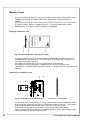
Memory Cards ................................................................................................................................. 50
Preparing the Memory Card ........................................................................................................ 50
Installation of the Memory Card ................................................................................................... 50
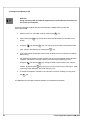
Formatting the Memory Card ....................................................................................................... 51
Writing on the Memory Card ........................................................................................................ 51
Printing from a Memory Card ...................................................................................................... 52
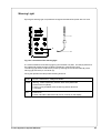
Warning Light .................................................................................................................................. 53
Warning Sensors ............................................................................................................................. 54
Warning Sensor Ribbon End ....................................................................................................... 54
Warning Sensor Label End .......................................................................................................... 55
Service Unit for Compressed Air ................................................................................................ ..... 56
Antistatic Brush ............................................................................................................................... 57
Appendices
Appendix A - Error Messages / Problem Solution .............................................................................A-1
Error Messages .............................................................................................................................. A-1
Correctable Errors ...................................................................................................................... A-1
Irrecoverable Errors .................................................................................................................... A-2
Errors During System Test ......................................................................................................... A-2
List of Error Messages ......................................................................................................... ...... A-3
Problem Solution ............................................................................................................................ A-6
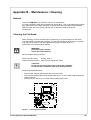
Appendix B - Maintenance / Cleaning ............................................................................................... B-1
General .......................................................................................................................................... B-1
Cleaning the Printhead ................................................................................................................... B-1
Printer-Applicator-System PAM 3000
5
Appendix C - Pin Assignment of the Interface Connectors ............................................................
Pin Assignment of the Serial Interface Connector .........................................................................
Pin Assignment of the Parallel Interface Connector .......................................................................
PLC Interface Port .........................................................................................................................
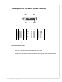
Pin Assignment .........................................................................................................................
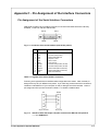
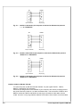
Circuit Diagrams of Inputs and Outputs .....................................................................................
Explanation of the Signals .........................................................................................................
Scanner Connector .......................................................................................................................
Pin Assignment .........................................................................................................................
Circuit Diagrams of Input and Output ........................................................................................
Explanation of the Signals .........................................................................................................
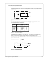
Example of a Circut Diagram ....................................................................................................
C-1
C-1
C-3
C-4
C-4
C-5
C-6
C-8
C-8
C-8
C-9
C-9
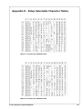
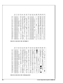
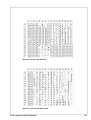
Appendix D - Setup Selectable Character Tables ............................................................................ D-1
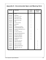
Appendix E - Spare Parts (Extract) ..................................................................................................... E-1
Index
Manufacturer's Declaration
6
Printer-Applicator-System PAM 3000
A General Guide to the Documentation
Operator's Manual
The present manual contains information on the characteristics, features, functions, and use
of the Printer-Applicator-System PAM 3000.
The manual covers general information which is necessary for operating the printer as well as
information about accessibility to different components of the printer.
Furthermore the loading of media and ribbon and the configuration in setup will be explained.
In the appendices, you will find useful additional information, such as internal character sets of
the printer, interface specifications, comments on possible error messages and printer
maintenance.
Note the directions for use on recommended material and comments on maintenance in order
to avoid damage and premature failure of your printer.
Every effort has been made in the creation of this manual to provide as much information as
possible in an understandable manner.
We welcome your comments and suggestions regarding additions or corrections to improve
future editions of this manual. Please, let us know if you have any questions.
Important information contained in this manual is marked as follows:
WARNING !
Impending danger!
May cause death or physical injuries.
CAUTION !
Dangerous situation !
May cause equipment/material damage or data loss.
NOTICE !
Helpful additional information and tips for use.
Further Documentation
The programming of the PAM 3000 printer is completely compatible to the programming of the
PAM 2000. Therefore it is possible to use the information, that can be found in the manual
"Programming Instructions - Apollo".
Detailed information about service and maintenance are included in the "Service Manual" of
the PAM 3000. (e.g. replacement of components, adjustment instructions, spare parts lists,
etc.)
Trademarks
Centronics ® is a registered trademark of Centronics Data Computer Corporation.
Macintosh-Computer is a product of Apple Computer, Inc.
Microsoft ® is a registered trademark of Microsoft Corporation.
Bitstream ® is a registered trademark of Bitstream, Inc.
Speedo is a registered trademark of Bitstream, Inc.
TrueType is a registered trademark of Apple Computer, Inc.
Printer-Applicator-System PAM 3000
7
1 Product Description
General Information
The Printer-Applicator-System PAM is especially developed for automatic labelling.
The system is composed of two main parts: printer module and applicator module.
The printer module PAM 3000 is equipped with a high-class 300 dpi printhead to print texts,
bar codes and graphics quick, brilliant and tidy.
The print mechanism is aligned to dispense labels. The transport system guarantees a high
precision in printing and applying labels independent from the size of the label supply roll. For
the receipt of the print data PAM 3000 has a serial RS-232-interface.
The printer is designated to work in the dispense mode. In this mode only each one label is
printed after the receipt of an start signal. The label is peeled-off from the backing paper by
moving back the peel-off table and taken by the pad. After removing the dispensed label the
peel-off table is moved back in the printing position. So the printing of the next label may be
started at the front label edge.
The applicator module PAM 3002 performs the transport of the labels from the peel-off
position (starting position) to the product (labelling position). The labels are transferred with a
pad, by two compressed-air driven pneumatic cylinders. A lift cylinder carries out the vertical
movement of the pad between the starting position and the labelling position and the turn
cylinder provides the turning movement of the pad between the 0°-position and the 90°position.
The labels could be applied parallel to the print line (0°-position) as well as across to the print
line (90°-position).
For the external control of the labelling process the PAM 3000 is equipped with a PLC
(programmable logic control) interface with potential free inputs and outputs. This interface is
especially used to start the printing and applying of the labels.
The PAM 3000 is an innovative label printer and applicator system which may be used in
either direct thermal or thermal transfer mode.
The double lined LCD display keeps the operator constantly informed about the current status
of the printer. The setup menu allows easy configuration changes whenever desired.
There are offered varied options to complete the print system.
Characteristics of the Thermal Printhead
CAUTION !
The thermal printhead is the most sensitive part of your printer.
Pay special attention to the following guidelines :
1) The glass cover on the printhead must not be touched with the hand. Do not use any sharp
items, such as knives or screwdrivers, to clean the printhead.
2) During printing, always take care that there is no dirt or foreign objects on the labels in order
to avoid impurification of the printhead. This way, the printhead might be damaged.
3) Use proper label material with a smooth surface only.
A rough surface will affect the printhead and may cause damage and reduce its operating
life.
4) Clean the printhead regularly with a special printhead cleaning pen, or an isopropyl alcohol
soaked cotton swab.
5) Print with the lowest possible printhead temperature.
Careful use will allow you to print approximately between 30 to 50 km of print media before
the printhead needs replacing.
Improper usage can cause damage to the printhead.
8
Printer-Applicator-System PAM 3000
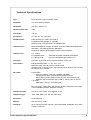
Technical Specifications
Type :
Direct thermal / Thermal transfer printer
Printhead :
Thin film transfer printhead
Resolution:
300 dpi = 12 dots / mm
Number of dots/ line :
1280
Print width :
108 mm
Print speed :
66, 100, 133, 166, 200 mm/s
Available fonts :
5 Bitmap fonts incl. OCR-A and OCR-B
2 scaleable fonts (Speedo) - internally
Speedo and TrueTypefonts - to load externally
Character sets :
Windows 95/98/NT4.00/2000, Windows 1252/1250, IBM Codepage 850/852,
ISO 8859-1, ISO 8859-8, EBCDIC, Macintosh
Supports all Western and Eastern European Latin characters
Character size :
0.9 - 128mm
For scaleable fonts :
For Bitmap fonts :
Font style :
bold, italic, underlined, mirror-inverted, outlined, revers, grey
Font rotation :
Bitmap fonts/Bar codes : 0°, 90°, 180°, 270°
Scaleable fonts : optional, texts in circular format
Speedo and TrueTypefonts : alignment degree for degree, text in circular
format and mirror-inverted
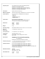
Bar codes :
Linear codes :
Code 39, Code 93, Code 128, Codabar, FIM, HIBC,
Interleaved 2/5, Ident-/Leitcode der Deutschen Post AG,
MSI, Plessey, Postnet, EAN-8, EAN-13, EAN-128, EAN/UCC 128,
EAN/UPC App 2, EAN/UPC App 5, JAN-8, JAN-13, UPC-A, UPC-E
2-D codes :
Data Matrix, PDF417, UPS-Maxicode
width and height are individually changeable
the size is selectable up to a factor of 10
Bar code height, modul width, and ratio are variable, with/without check digit,
human readable character, start/stop character
Graphic elements :
Line, box, circle, ellipse, fill-in segment, arrow
Graphic file type:
.PCX, .IMG, .BMP, .TIF, .GIF and .MAC files
Processor :
32 Bit, Motorola
Memory :
Internal memory 2 MB
Interfaces :
serial : RS-232, RS-422, RS-485, 1200-57600 Baud, 8 Data Bits, even parity
parallel : Centronics
Printer-Applicator-System PAM 3000
9
10
Peripheral ports :
PLC-interface for the control of the labelling process
Interface for connecting the scanner
Interface for connecting the warning sensor label end
Interface for connecting the warning sensor ribbon end
Interface for connecting the warning light
Test feature :
System test when switching on
Material recognition :
Gap sensor (See-trough), adjustable from 3 until 48 mm in the width
Control features :
Print stop and error message at the LCD display at
- Paper out
- Ribbon out
- Transport system open
- Applicator errors
Control panel :
4 Function keys with LED display
Backlit LCD with 2 lines of text, 16 characters per line
LCD can be set to display in 9 different languages
Dimensions :
Height :
Width :
Length :
Weight :
35 kg
Operating voltage :
Switcheable between 230 V A.C/ 50 Hz or 115 V A.C/ 60 Hz
Maximum
power input :
1.5 A (at 230 V) / 3 A (at 115 V)
Circuit protection :
T 4 A (at 230 V) / T 6.3 A (at 115 V)
Compressed
air supply :
Operating pressure : 5 bar
Air connector : Push-in fitting for a 8 mm tube
Filter : 5 µm
Environment :
Operation at 10° to 35°C at a humidity of 30 to 85%
Transport at -25° to +70°C at a max. humidity of 95%
non-condensing
Storage at 5° to 40°C at a humidity of 5 bis 85%
Tolerance of the print :
+/- 0.3 at a print speed of 66 mm/s and 100 m media roll
increasing with the size of the media roll
Tolerance measure :
0.6 mm at a print speed of 66 mm/s and 100 m media roll
0.8 mm at a print speed of 66 mm/s and 150 m media roll
1.0 mm at a print speed of 66 mm/s and 180 m media roll
Measures determinded with material of the manufacturer according to the
conditions of the manufacturer.
Demand mechanism :
"Shuttle"
Patent-No. : 5,300,160
Patent date : Apr. 5, 1994
Peel-off table dim. :
Length :
Width :
420 mm
290 mm
530 mm
120 mm
20 mm
Printer-Applicator-System PAM 3000
Label material :
Thermal paper, Velin paper, Thermal transfer paper
Various synthetics including : PE, PP PVC, Polyamid, Polyimid
Liner width :
25 mm until 120 mm
Label height :
3,5 mm until 80 mm
Supply roll diameter :
max. 200 mm
Core diameter :
76 mm
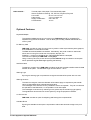
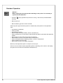
Optional Features
Keyboard Adapter
The keyboard adapter allows you to connect your PAM 3000 to a MF-2 compatible PC
keyboard using the serial interface. This will allow you to modify variable data stored on a
memory card.
PC Memory Card
PAM 3000 includes an option for using memory cards in order to permanently store graphics,
fonts, databases or whole label formats.
The data can be downloaded via interface. Alternatively, the printer is able to read cards
which were on using PC card drives of computers, lap-tops, etc.
PCMCIA 2.1 conforming sRAM cards or Flash-EPROM cards are accepted.
The maximum capacity for PAM 3000 is 4 MegaByte.
Using a memory card, the printer can be operated without being connected to a computer
which represents a great advantage regarding the flexibility.
Interface Cable
The delivery program of the PAM 3000 includes a serial and a parallel interface cable for data
transfer as an option. The standard length of each cable is 1.50 m.
Warning Light
By using the warning light it is possible to recognize the state of the printer with one view.
Warning Sensors
The sensors recognize, when the diameter of the label supply roll respectively the transfer
ribbon roll decreases below a preset thresould value.
The messages of the sensors are only intended to inform the operator. They do not influence
the operation of the PAM 3000, i.e. the operation is not interrupted.
The messages will be shown by switching on the yellow lamp of the warning light (option).
The signals also can be sent to a control system by using the peripheral interface.
Air Service Unit
PAM 3000 includes an option for adjusting and filtering the compressed air.
Antistatic Brush
By using the antistatic brush option it is possible to reduce the electrical charge in the print
area.
Printer-Applicator-System PAM 3000
11
Print Media
PAM 3000 can be operated in direct thermal as well as thermal transfer mode.
For direct thermal mode, only use print material with a thermal-reactive coating.
The print image is transferred by heating the material at the printhead, causing a reaction on
the surface of the paper and, consequently, darkening the material.
In thermal transfer mode, not only standard paper labels are needed but also the thermal
transfer ribbon with a color surface. The printout is created by heating the transfer ribbon,
causing a transfer of color particles onto the label.
PAM 3000 allows to regulate the heat level and also the print speed. Thus, the printer offers a
wide range of opportunities for usage.
PAM 3000 is able to print on labels with a maximum supply roll diameter of 200 mm and a
core diameter of 76 mm.
The ability of label edge recognition, which guarantees the precise position of the printer
output, is accomplished by a photocell. This sensor is controlled by the processor of the
PAM 3000 and ensures recognition for different sorts of material. There is no need for additional electronic adjustment.
On the following pages, you will find detailed information and specifications concerning
suitable materials.
Print Media for Direct Thermal Printing
The print material must correspond to several important specifications, in order to ensure high
quality printing, and to avoid damage to the printhead or early wear.
Using labels which we have tested and which we recommend to our customers, will guarantee
a gentle treatment of the printhead. If you want to use material by another supplier, please
note the following requirements regarding the condition of thermal printer paper :
To avoid damage to the printhead, the surface coating must cover the thermal-reactive
layer. If the coating is too thin, this may cause a 'pitting' effect on the printhead, i.e. very
small explosions during the chemical reaction of the thermal coating quickly resulting in
damage to the printhead.
The surface of the labels should be very smooth to avoid a 'sandpaper' effect on the
printhead.
Always choose material which can be printed on with the lowest possible heat level. The
greater the heat level, the shorter the life of the printhead. Moreover, with highest heat
levels the phases of heating up and cooling down extend. This may have a negative effect
on the print quality, especially if a high print speed is required.
Print Media for Thermal Transfer Printing
In thermal transfer mode, a wide range of different label materials may be used. (e.g. normal
paper, tag stock, a variety of synthetic material such as polyester foil, etc.)
NOTICE !
The print quality greatly depends on the right combination of label material and
transfer ribbon. The surface of the labels determines which ribbon material may be
used. Unsuitable ribbons may cause an extremely poor print image.
12
Printer-Applicator-System PAM 3000
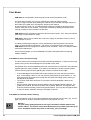
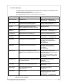
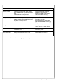
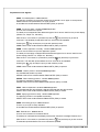
Label Media Specifications
Label media to be used for the PAM 3000 can be found in the table below. Note this
information before ordering your labels.
G
H
K
I
E
D
C
F
A
B
Fig. 1
Index
Label formats
Characteristics
MIN. (mm)
MAX. (mm)
A
Label width
5
115
B
Width of silicon liner
25
120
C
Label length
3.5
80
D
Gap between label
2
546
E
Label thickness
0.1
0.25
F
Thickness of silicon liner
0.05
0.10
G
Distance of the first printing point
from the edge of silicon liner
H
Distance of the label sensor
from the edge of silicon liner
I
Width of the perforation mark
5
-
K
Height of the perforation mark
2
5
2
variable
Table 1a Label formats in mm
Printer-Applicator-System PAM 3000
13
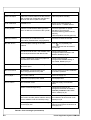
Transfer Ribbon
The choice of a suitable transfer ribbon is important for the print quality of your printer as well
as the useful life of the printhead.
CAUTION !
Transfer ribbons of inferior quality may cause premature deterioration of
the printhead !
The ribbon material must be antistatic, because the extremely thin surface coating of the
thermal printhead can be damaged by electrostatic discharge.
Also, the material must be extremely resistant to high temperatures to avoid melting the ribbon
with the printhead.
The heat which arises during printing must be carried off by the label and by the transfer
ribbon itself. Transfer ribbons of inferior quality are often poor heat conductors. This may
cause overheating of the printhead in spite of electronic protection.
Poor transfer ribbons also tend to lose parts of the coating which leads to accumulating dirt on
the printhead and the sensors. With some ribbons the color rubs off and soils the printhead.
All of these effects contribute to poor print quality.
We have carried out numerous tests with many different ribbons and we recommend you use
transfer ribbons made by well-known/ brand manufacturers only. Depending on the label
material, several transfer ribbons may be suitable.
The quality of print is determined by the right combination of these materials.
The recognition of the transfer ribbon is sensed by the rotation control of the transfer ribbon
unwinder, rather than by photocell sensors. As a result, ribbons with a thinner coating or those
with a colored coating can be used safely. To be able to print all labels up to the exact end of
the transfer ribbon, the length of the uncoated trailer is limited.
NOTICE !
When buying transfer ribbons, make sure that the trailer of the ribbon has a
maximum length of 150 mm. Also note that the trailer easily can come loose from
the cardboard core.
Index
A
Characteristics
MIN. (mm)
MAX. (mm)
Width
25
114
Length
-
360
25
25
Core diameter
Inking
external
Table 1b Ribbon formats in mm
14
Printer-Applicator-System PAM 3000
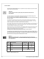
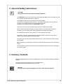
2 General Safety Instructions
CAUTION !
Pay special attention to the following safety guidelines :
- The PAM 3000 printer is built exclusively to print labels and tags, continuous paper, etc. Do
not use other materials than listed in chapter 1.
- Connect the printer only to an outlet with the correct voltage !
The printer is configured for either 230V or 115V power supply, which can be switched
using the input voltage selector at the right side of the printer.
Connect only to a power outlet with a grounded contact.
- The printer must only be connected to devices which have extra low voltage.
- Power must be OFF before plugging in any accessory or connecting the printer to a
computer, etc. Also switch power off on all appliances before disconnecting.
- Do not expose the printer to any moisture, or use in damp or wet areas.
- In operation, moving or rotating parts are easily accessible. Therefore, keep long hair,
jewelry, loose clothes away from the these parts.
- During the print process the printhead will become hot. Use extra caution when touching
the printhead.
- Before starting any maintenance, switch the printer OFF and disconnect it from the power
supply.
- Only qualified trained service technicians should attempt to repair your printer if damaged
or in need to repair.
3 Delivery Contents
Inspect the packaging and contents immediately after receipt for possible damage caused by
shipping.
The supplied equipment depends on the requested options.
Compare the delivered accessories with your order.
NOTICE !
Please keep the original packaging in case the printer must be returned.
Printer-Applicator-System PAM 3000
15
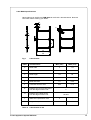
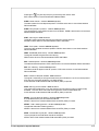
4 Component Location
Printer
15
14
13
12
11
10
1
2
3
9
4
5
6
Fig. 4a
1
2
3
4
5
6
7
8
9
10
11
12
13
14
15
16
-
7
8
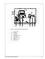
Front view
Display
Function keys with indicator LEDs
Ribbon take up hub
Ribbon supply hub
Print mechanism
Guide roller
Media rewind hub
Knurled knob
Adapter
Flange
Media supply hub
Swing arm with guide roller
Pre-dispense key (for applicator)
Electronic connector for the applicator
Air connectors for the applicator
Printer-Applicator-System PAM 3000
1
2
3
4
5
6
Fig. 4b
1
2
3
4
5
6
7
8
9
10
11
-
7
8
9
10
11
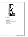
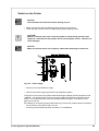
Detailed view of the print mechanism
Adjusting plate
Printhead
Print roller
Feed roller
Pinch roller
Transport locking lever
Peel-off table
Label edge sensor
Brake
Media guide axle
Media guide
Printer-Applicator-System PAM 3000
17
1
2
12
3
4
Fig. 4c
1
2
3
4
5
6
7
8
9
10
11
12
18
-
5
11
6
11
7
10
8
9
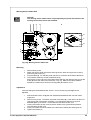
Side view
Connector for the compressed air
Power connector with power switch
Parallel interface port
Serial interface port
Scanner connector
Connector warning sensor transfer ribbon end
Connector warning sensor label end
PLC interface port
DIP switches
Connector warning light
Silencer
Memory card module slot
Printer-Applicator-System PAM 3000
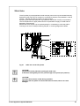
Applicator
6
5
4
3
1
Fig. 4d
1
2
3
4
5
6
-
2
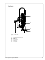
Front view
Connector for the electronics
Pad holder
Pad
Turn cylinder
Slide valve
Lift cylinder
Printer-Applicator-System PAM 3000
19
5 Mounting the Applicator
Installation
1
2
1
4
1
4
3
1
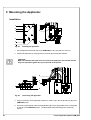
Fig. 5a
Installing the applicator
1. Put the applicator at the left side of the PAM 3000 printer using the four holes (1).
2. Fasten the applicator by screwing the four screws (4) including the washers.
CAUTION !
Make sure that the two bolts at the rear side of the applicator are inserted into the
long hole (2) and the guide hole (3) on the side of the printer.
5
6
7
8
Fig. 5b
Connecting the applicator
3. Plug the connector of the applicator's electronic system (7) in the peripheral port (6) of the
PAM 3000 printer.
4. Push the compressed air tubes of the applicator (5) into the appropriate push-in-fittings (8)
on the top of the PAM 3000 printer. The appropriate tubes and fittings are marked by
figures.
20
Printer-Applicator-System PAM 3000
Slide Valve
The lift cylinder (1) is equipped with a slide valve (2), which can only be actuated manually.
By delivering the slide valve is closed so it is possible to keep the compressed air in the lift
cylinder. That way the pad (3) is hold in its upper position.
By opening the slide valve (slide the ring upwards to the position "bleed") it is possible to
remove the pad from its upper position as the compressed air supply is closed and the
applicator is switched off.
But the slide valve should only be opened (bleed) if it is necessary to move the pad for
mounting or service for example cleaning the pad, or removing fragments of labels.
1
2
2
3
Fig. 5c
Slide valve at the lift cylinder
CAUTION !
Pay attention to the pad while opening the slide valve.
It should be swung away from the peel-off edge of the printer (90°-position).
CAUTION !
The slide valve must be closed during operation.
Otherwise the lift cylinder can be moved without control, which can cause
damages.
Printer-Applicator-System PAM 3000
21
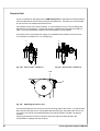
Pad Unit
Versions
The pad unit consists of the pad holder, the pad and the blow tube. The format of the pad
holder and the pad depends on the label format.
So there are two different versions of the pad holder, the small format (type 1200) and the
large format (type 1100).
The small format is recommended for use of small labels with a height up to 25 mm.
The pad is specific designed for each label format which is used.
When applying large labels it is necessary to mount a blow tube additionally.
Small format
Large format
1
2
1
2
Fig. 5d
Front view pad holder (1) and pad (2)
Small format
Large format
1
2
1
2
Fig. 5e
22
Side view pad holder (1) and pad (2)
Printer-Applicator-System PAM 3000
Mounting
Normally all supplied label applicators have passed a previous run at the factory. Therefore all
units including the pad holder and the pad which are necessary for the operation of the device
are mounted.
But it is possible to dismantle the pad holder and the pad without effort when the label format
is changed. Following it is very easy to mount the new pad holder or pad.
Small format
1
Fig. 5f
2
Large format
3
2
1
3
Changing the pad
Changing the pad :
1.
2.
3.
4.
5.
6.
Remove the vacuum tube (2) from the pad (3).
Loosen the screw on the lower side of the pad (3).
Remove the pad (3).
Attach the new pad to the pad holder (1).
Fasten the new pad on the pad holder (1) using the screw.
Attach the vacuum tube (2) to the new pad.
Small format
4
4
Fig. 5g
Large format
5
1
Changing the pad holder
Changing the pad holder :
1.
2.
3.
4.
5.
6.
7.
8.
9.
Dismount the pad (3).
Loosen the screw on the lower side of the cover (4).
Remove the cover (4).
Loosen the screw (5) at the pad holder (1).
Remove the pad holder (1).
Attach the new pad holder to the bolt.
Fasten the new pad holder by screwing the screw.
Mount the cover.
Mount the pad.
Printer-Applicator-System PAM 3000
23
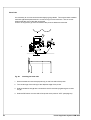
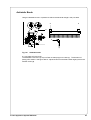
Blow Tube
It is necessary to mount a blow tube when applying large labels. This way the label is additional blown against the pad with an air current coming from the blow tube. The air current
supports the take-over of the label by the pad.
There is an equipment (1) at the front side of the printer to attach the blow tube.
1
2
Fig. 5h
3
4
Installing the blow tube
1. Screw the blow tube into the equipment (1) on the front side of the printer.
2. Turn the drillings of the tube (3) to the dispense edge of the printer.
3. Hold the slotted screw (4) with a screwdriver and fix the tube by tightening the counter
nut (2).
4. Slide the DIP-switch 4 on the side of the printer to the position "OFF" (see page 34).
24
Printer-Applicator-System PAM 3000
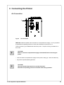
6 Connecting the Printer
Air Connection
1
Fig. 6a
Air connection
PAM 3000 needs for operation the connection to a compressed air supply. It is very important
to guarantee an operating pressure of 5 bar with a tolerance of plus/minus 5 % .
The air connector (1) is located at the side of the printer. The push-in-fitting is suitable for a
8mm-tube.
CAUTION !
Make sure that the compressed air supply is switched off while connecting the
printer.
Insert the tube of compressed air supply into the push-in-fitting (1). Insert the tube firmly.
Adjust the required operating pressure.
CAUTION !
Use only filtered compressed air to operate the printer.
Guarantee an operating pressure of constant 5 bar during operation.
Printer-Applicator-System PAM 3000
25
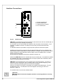
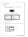
Interface Connections
1
2
1 - Parallel interface port
2 - Serial interface port
3 - Interface port for scanner
4 - PLC interface port
3
4
Fig. 6b
Interface ports
PAM 3000 is equipped with three serial interfaces, these are RS-232, RS-422, and RS-485, all
of them using the 25 pin interface connector (2).
In most cases, you can use the RS-232 interface for the connection to the computer. If your
computer is located more than 15m away from the printer you should use the RS-422
interface.
The RS-485 interface is provided for using the printer as part of a networked system.
In addition to the serial port, the printer also provides a parallel (Centronics) interface which
offers a faster transfer of data than the serial interfaces. Therefore, we recommend to use the
parallel interface for those applications where a large number of loadable fonts or complex
graphics have to be printed.
For the Centronics interface use the 36 pin interface connector (1).
Additionally PAM 3000 has a PLC interface with 25 pin connector (4). This interface is needed
for embedding the printer in the process control of a higher system and is especially used to
start the printing and applying of the labels.
PAM 3000 is also equipped with a 9 pin connector (3) to connect a scanner. This way it is
possible to check a printed bar code immediately after printing and before applying. If the
scanner sends the goodread-signal then the label can be applied.
If there is no scanner connected it is necessary to simulate the goodread-signal. This can
be realized by a plug. An example for the circuit diagram of this plug you can find in
appendix C page C-9.
The interfaces are to connect with suitable cables.
CAUTION !
Make sure that all connected computers and their connecting cables are correctly
grounded.
26
Printer-Applicator-System PAM 3000
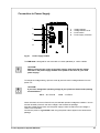
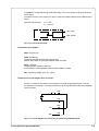
Connection to Power Supply
1
1
2
3
4
2
-
Voltage selector
Voltage selector cover
Power switch
Power supply connector
3
4
Fig. 6c
Power supply module
The PAM 3000 is designed for use with 230V A.C/ 50Hz (standard) or 115V A.C/60Hz.
CAUTION !
Before connecting the printer to the power supply, make sure that the voltage
selected on the power supply module of the printer is the same as your main
power supply !
To change the voltage setting, open the cover (2) and remove the voltage selector from the
power unit.
CAUTION !
If you have changed the operating voltage of your printer the fuses need replacing
as stated below !
230 V - 2 x T 1.5 A
115 V - 2 x T 3 A
When delivered, the correct fuses for the pre-selected operative voltage are installed. You will
find the necessary fuses for the other voltage in the accessories package.
Slide the voltage selector back into the power supply module so that the correct voltage is
visible in the lid window.
Connect the printer to a grounded outlet using the power cable supplied in the accessories
package.
Printer-Applicator-System PAM 3000
27
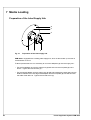
7 Media Loading
Preparation of the Label Supply Hub
4
3
3
1
Fig. 7a
1
2
Preparation of the label supply hub
PAM 3000 is equipped with a rotating label supply hub, which is able to take up rolls with a
core diameter of 76 mm.
To take up these label rolls it is necessary to mount two adapters (3) onto the supply hub :
Put the first adapter (3) onto the supply hub (2) and slide it to the wind plate (4) until it
blocks. Tighten the knurled srew (1).
Put the second adapter onto the supply hub (2) and slide it against the wind plate until the
distance between the outer edge of the adapter and the wind plate (4) is a little less than
the width of the label roll. Tighten the knurled screw (1).
28
Printer-Applicator-System PAM 3000
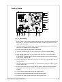
Loading Labels
1
2
3
4
5
6
7
Fig. 7b
8
9
10
11
12
13
Media loading
1. Place the label roll (1) onto the prepared media supply hub (4) and slide it down against the
wind plate (3). The solid line represents the feed path of outside-rolled labels, the broken
line of inside-rolled labels.
2. Put the flange (5) on the supply hub (4), slide it down against the label roll (1) and fix it at
the supply hub by tightening the knurled knob (2).
3. Slide the media guide (11) outwards as far as possible.
4. Unlock the transport locking roller (7) by pressing the knurled knob (8) downwards.
5. Unroll a length of label stock from the media roll and feed it first to the printhead (9) as
shown in figure 7b.
It is particularly important to ensure that the media strip slides properly through the fittings
of the photocell assembly (10).
6. Feed the label stock out of the side of the printer until there is enough material to reach the
internal rewinder.
7. Take off all labels from the outstanding liner, and feed the liner as shown in figure 7b to the
internal rewinder (12).
8. Slide the media strip under the rewinder clamps (6) to the wind plate. Hold the rewinder
and turn the knurled knob (13) clockwise. That way the label strip will be fixed at the
rewinder.
9. Turn the rewinder (12) clockwise for tightening the label strip.
10. Press the knurled knob (8) upwards to close the transport system.
11. Slide down the guide (11) against the upper edge of the label strip.
Printer-Applicator-System PAM 3000
29
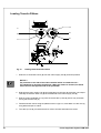
Loading Transfer Ribbon
4
1
5
2
6
3
Fig. 7c
Loading thermal transfer ribbon
1. Slide the roll of transfer ribbon (4) onto the ribbon supply hub (5) as far as possible.
NOTICE !
Pay attention to the side of the ribbon material which is coated with ink !
The inked side is generally the dull side. When the ribbon is inserted, the inked
side must face the opposite side of the printhead !
2. Hold tight the ribbon supply hub (5) and rotate the knurled knob (6) clockwise until it stops.
That way the transfer ribbon roll (4) will be attached to the ribbon supply hub (5).
3. Slide an empty cardboard core (1) onto the ribbon take up hub (2) and fix it by clockwise
turning the knurled knob (3).
4. Feed the transfer ribbon along the path as shown in figure 7c, then attach it to the core (1)
using adhesive tape or a label.
5. Turn take up hub (2) counterclockwise in order to smooth and stretch the ribbon.
30
Printer-Applicator-System PAM 3000
8 Adjustments
All supplied label applicators have passed a previous run at the factory. Therefore, the basic
adjustments which are necessary for the operation of the device have been carried out.
It may be useful to do some more fine tuning when the applicator is installed. This refers
mainly to mechanical parameters, which are depending on the format of the labels as well as
some special settings for the type of operation.
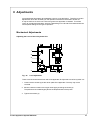
Mechanical Adjustments
Adjusting the Level of the Lift Cylinder Unit
1
2
2
1
3
Fig. 8a
Level adjustment
There are three screws at the front side of the applicator to adjust the level of the cylinder unit.
1. Loosen the two screws (1) at the carrier plate of the applicator. But they may not be
removed.
2. Move the whole unit within the longish holes (2) by screwing the screw (3).
The pad has to be located slightly above the dispense table of the printer.
3. Tighten the screws (1).
Printer-Applicator-System PAM 3000
31
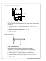
Adjusting the Sides of the Lift Cylinder Unit
1
2
Fig. 8b
Side adjustment
At the rear side of the carrier plate of the applicator there are two screws to adjust the sides of
the cylinder unit.
1. Loosen the two screws (2) at the carrier plate of the applicator. But they may not be
removed.
2. Move the whole unit within the longish hole (1).
Adjust until the dispensed label is aligned centrally to the pad.
3. Tighten the screws (2).
Tuning of the Blow Tube
1
Fig. 8c
2
3
Tuning the blow tube
When applying large labels it is necessary to install a blow tube additionally.
The blow tube (2) for the supporting air can be rotated around its longitudinal axis.
By rotatinge the blow tube the direction of the air current is changed (adjusting the blow
openings to the dispense edge of the printer).
1. Loosen the lock nut (1) as well hold the slotted screw (3) with a screwdriver.
2. Adjust the tube until the air current is aligned with the dispense edge of the printer.
3. Tighten lock nut (1).
32
Printer-Applicator-System PAM 3000
Adjusting the Label Edge Sensor
1
2
Fig. 8d
Adjustment of the label edge sensor
To accommodate a variety of print jobs, the position of the label edge sensor (1) can be
adjusted until it is at the proper sensing position. This setting is particularly useful when the
labels to be printed are narrow, perforated, bear reflective markings, or are labels which are
not square or rectangular in shape.
It is important to ensure that the sensor itself (the position of which is indicated by a green
mark in the sensor housing) is positioned so that the space between the labels can be
recognized by the photocell. In the case of labels which have an unconventional shape (ie.
not square or rectangular), the photo cell should be positioned at the leading edge of the label.
Adjustment of the sensor is performed by sliding the whole label edge sensor in and out.
It is recommended to use the pin-tool (2) included in the delivery contents for positioning the
sensor.
Printer-Applicator-System PAM 3000
33
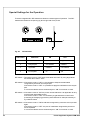
Special Settings for the Operation
There are integrated four DIP-switches to determine several types of operation. The DIPswitches are located in the opening (1) at the right side of the printer.
1
Fig. 8e
DIP-switches
DIP-switch
Parameter
ON
OFF
1
Label format
small
large
2
Recycle part
not installed
installed
3
Applicator
installed
not installed
4
Print repeat
no
yes
DIP-switch 1-This switch is set on "ON" when small labels are used. By using large labels
the switch has to set on "OFF".
DIP-switch 2- If the switch is set on "ON" it is not possible to dispose the bad labels
recognized by a scanner at a recycle part.
If the switch is set on "OFF" it is possible to apply the bad labels on the recycle
part.
It is recommended to set the switch always on "ON" if no scanner is used.
DIP-switch 3- If the switch is set on "ON" the printer notices that there is an applicator to carry
out the further steps after printing.
If the switch is set on "OFF" it is necessary to guarantee the correct further
processing of the applying process by other features for example manually or
by industrial robots.
DIP-switch 4- If the switch is set on "ON" a bad label recognized by a scanner will not printed
again.
If the switch is set on "OFF" the print of a bad label recognized by a scanner
will be repeated.
It is recommended to set the switch always on "ON" if no scanner is used.
34
Printer-Applicator-System PAM 3000
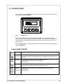
9 Control Panel
The control panel of the PAM 3000 is fitted with 4 function keys with indicator LEDs, and a
2x16 character digital LCD display.
Fig. 9
Control Panel
The control panel display constantly provides the operator with the actual information
concerning the current printer mode and label processing. The indicator LEDs support the
information shown in the display by indicating which keys have to be pressed (e.g. in the
event of a fault).
On the following pages, you will find descriptions of the key functions in the several system
modes of PAM 3000.
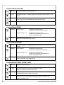
System Mode ONLINE
ONL key
Switch into OFFLINE mode (LED ONL off)
FF key
Provides label feed. The leading edge of the next label to be printed is in print
position.
CAN key
Deletes data of the previous print job in internal memory.
Following that, "Pause reprint" is not available.
(see PSE key)
PSE key
Repeats the print of the last label, after the previous print job has been
completed. (only if setup parameter 'Pause reprint' is on)
ONL key
+
CAN key
Pressing both keys together for at least 5 seconds will switch into the
SETUP mode.
(LED ONL off)
Printer-Applicator-System PAM 3000
35
System Mode OFFLINE
ONL key
Switch into ONLINE mode (LED ONL on)
FF key
Provides label feed. The leading edge of the next label to be printed is in print
position.
CAN key
Switch into LABEL FROM CARD mode.
(only if memory card is installed and formats are stored on it)
PSE key
Display shows printer info display (information about printer settings)
System Mode PRINT
CAN key
PSE key
short pressing :
Cancels the current print job,
Switch to the next job in the input buffer
longer pressing (>1s):
Cancels the current print job,
Deletes the input buffer (LED CAN blinks),
Switch into ONLINE mode
Interrupts the current print job,
Switch into PAUSE mode (LED PSE on)
System Mode PAUSE
FF key
Provides label feed. The leading edge of the next label to be printed is in print
position.
CAN key
short pressing :
Cancels the current print job,
Switch to the next job in the input buffer
longer pressing (>1s):
Cancels the current print job,
Deletes the input buffer (LED CAN blinks),
Switch into ONLINE mode
PSE key
Continues the current print job,
Switch into PRINT mode (LED PSE off)
System Mode LABEL FROM CARD
36
ONL key
Switch into OFFLINE mode
FF key
For scrolling down within the file list stored on the card
Reduces the quantity of labels to be printed
CAN key
For scrolling up within the file list of the card
Increases the quantity of labels to be printed
PSE key
Confirms file selection
Moves the cursor to the right when setting the quantity of labels to print
Switch into PRINT mode
Printer-Applicator-System PAM 3000
10 Setup
Using the setup mode, the configuration of the PAM 3000 may be customized to suit specific
requirements. Initial setup should be performed when operating the printer for the first time.
Changes which become necessary to process different print jobs, e.g. when different
materials are used, can mostly be accomplished by changing the software settings.
Start of Setup Mode
This mode is initiated by either simultaneously pressing down the
key and the
key
when switching on the printer and keep them pressed until the system test is completed, or in
ONLINE mode, press the same two keys down for at least 5 seconds.
Starting the setup mode, the display shows "SETUP" for about one second, followed by
"Country" which represents the first of the parameters to select from. Depending on the
selection, the setup parameters and their settings will be shown. The list of parameters is
brought up in a row and may be run through repeatedly.
Each time a parameter setting has been changed, there will be a request for confirmation.
There will not be a general request before leaving the setup mode.
Leaving the Setup Mode
The setup mode can be left at any point by pressing the
key. The confirmed parameters
will be saved.
If an already confirmed setting is not desired any more, switch off the printer during the setup
mode to cancel changes.
Restore the Default Setting
To return to the original factory default settings, press all three keys, the
and the
key, the
key,
key simultaneously while switching on the printer and keep them pressed down
until the display shows "--- RESTORE ---".
Function Keys in System Mode SETUP
ONL key
Stores the chosen and confirmed settings of the setup-parameters and
completes the SETUP mode.
(i.e. switch into ONLINE mode (LED ONL on)
FF key
Skips to next setup parameter.
Reduces numerical setup values.
CAN key
Skips to previous setup parameter.
Increases numerical setup values.
PSE key
Confirms selected settings for parameters.
Printer-Applicator-System PAM 3000
37
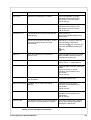
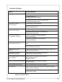
Overview of the Setup Parameters
Country
Deutschland
Belgie
Country setting : LCD display language
Formats of date and time
Measuring unit ( USA: inch, all other: mm)
France
Suomi
Transfer Print
On
RS-422
Baud rate
Protocol
RS-485
Baud rate
Network address
Centronics
This function is not usable for PAM 3000.
- x.x mm
± x.? mm
± ?.x mm
Printhead pos.
The parameter defines the location of the print image on the label.
X: x.x mm
X: x.? mm
X: ?.x mm
Offset of the print image across the transport direction
Y: - y.y mm
Y: ± y.? mm
Y: ± ?.y mm
Heat level
38
Top-Reflect
Setting of the interface type
Peel position
+x
Suisse
Danmark
Setting of the label recognizing method
Interface
Y: + y.y mm
Y: ± y.? mm
Y: ± ?.y mm
Schweiz
Ceska republica
Off
Gap sensor Bottom-Reflect
+ x.x mm
± x.? mm
± ?.x mm
USA
España
Setting of the print mode : Direct Thermal or Thermal Transfer
Label sensor
RS-232C
Baud rate
Protocol
United Kingdom
Italia
Offset of the print image in transport direction
Basic adjustment of the darkness (depending on the printhead)
"-9" indicates the lightest and "+9" indicates the darkest setting.
-x
Printer-Applicator-System PAM 3000
Printer info
Version xxxxx
The parameter provides information about the firmware, the cumulative
length of printed media and the number of operating hours.
xxx m / xxx h
Set date
DD.xx.xxxx
Setting of the system date (day, month, year)
xx.MM.xxxx
Set time
hh.xx.xxxx
xx.xx.YYYY
Setting of the system time (hour, minute, second)
xx.mm.xx
Character set
xx.xx.ss
Setting of the character set
Windows 1252 Windows 1250 ISO 8895-1 Codepage 850
EBCDIC
Macintosh Codepage 852 ISO 8895-8
Format Card
No
Command to format a PCMCIA card
Yes
Copy Memory Card
Yes
Command to copy a PCMCIA card
No
Backfeed
head down
This function is not usable for PAM 3000.
head lift-off
Debug mode
Off
The "Debug mode" represents a tool for the firmware programmer only.
On
Pause reprint
If the paramter is active, after completion of a print job, the print of the last
label may be repeated by pressing the
On
key.
Off
Printer-Applicator-System PAM 3000
39
11 Printer Info Display
Viewing the Printer Info Display
PAM 3000 offers a convenient option for retrieving and viewing information about the printer
configuration and occurred hardware problems without using setup mode or test print mode.
After switching on, or completing the system test or print jobs, the printer is in ONLINE mode.
Pressing the
key will switch into OFFLINE mode where the display shows the status
information on ten different pages which are accessible by repeatedly pressing the
The printer info display can be exited by pressing the
key.
key (back into ONLINE mode) .
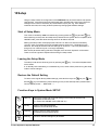
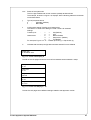
Definition of the Printer Info Display
Printer info
1: RS 232 / RTS/CTS
Fig. 11 a Printer info display 1
On the first page, the selected interface (default setting : RS232) and the handshake or
protocol (default setting : RTS/ CTS) will be shown.
Printer info
2: 9.600
Fig. 11 b Printer info display 2
The second page contains information about the fixed baud rate of the serial interface (default
setting : 9600).
Printer info
3: 2.58 / Aug
15
01
Fig. 11 c Printer info display 3
On the third page, the version and the date of the firmware are shown.
The example as shown in figure 11c represents the firmware version No. 2.58 as at Aug 15,
2001.
Printer info
4: 0000 / 2 / 5 / C
Fig. 11 d Printer info display 4
The fourth page of the info display contains coded information on the configuration of the
printer and the internal test results in the format "xxxx / y / z / C".
40
Printer-Applicator-System PAM 3000
xxxx
Result of the system test
The four-digit hexadecimal number contains (coded) hardware faults.
The example, as shown in figure 11d, displays "0000" indicating that there have been
no hardware faults.
y
Type of peripheral device
2
:
Applicator (Default)
3
:
None fitted
z
Configuration setting Transfer print/ Label sensor
The value of z results from adding the code numbers for selected
settings.
Transfer print
:
1
=
ON (Default)
0
=
OFF
Label sensor
:
8
=
Bottom-Reflect
4
=
Gap sensor (Default)
0
=
Top-Reflect
For example, Figure 11d : "5" - Transfer print ON (1) + Gap sensor (4).
C
Indicates that the setup configuration has been altered from the defaults
Printer info
5: Windows 1252
Fig. 11 e Printer info display 5
The fifth of the info pages shows the name of the character set as selected in setup.
Delay time
0 ms
Lock time
0 ms
Support del. off
250 ms
Blow time
0 ms
Support delay on
0,0 mm
Fig. 11 f Printer info display 6 - 10
The last five info pages show different settings related to the applicator module.
Printer-Applicator-System PAM 3000
41
12 Monitor Mode / ASCII Dump Mode
If programming directly, the monitor mode provides a method to print control sequences which
were received at the interface. The commands will be printed in text format depending on the
selected character set. Error messages will be printed directly behind the fault, e.g. for
unknown commands.
NOTICE !
In monitor mode, the printer will not recognize gaps between labels nor control
the ribbon feed.
For questions or future reference, print and retain one copy of the label format for each label
printed.
Start of Monitor Mode/ ASCII Dump Mode
To start the monitor mode, press the
key while switching on the printer, and keep it
pressed down until the system test is completed. The display shows "ASCII Dump Mode".
Following send a print job to the printer and then press the pre-dispense key to print out the
contents of the label.
In monitor mode, the print of data will be started after every four lines of data received.
Therefore, in some cases, the last lines of the label have to be retrieved by pressing the
key.
To cancel ASCII Dump mode, press the
key.
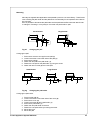
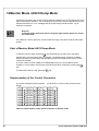
Representation of the Control Characters
The control characters (ASCII Code 00 ... 31) as shown in monitor mode printouts are as
follows.
Code
Printout
DEC HEX
Code
Printout
DEC HEX
Code
Printout
DEC HEX
Code
Printout
DEC HEX
00 00
08
08
16 10
24 18
01
01
09 09
17 11
25 19
02
02
10 0A
18 12
26 1A
03
03
11 0B
19 13
27 1B
04
04
12 0C
20 14
28 1C
05
05
13 0D
21 15
29 1D
06
06
14 0E
22 16
30 1E
07
07
15 0F
23 17
31 1F
Table 12 Representation of the control characters in monitor mode
42
Printer-Applicator-System PAM 3000
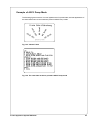
Example of ASCII Dump Mode
The following figures show the "normal" appearance of a printed label, and the appearance of
the same label when its commands are printed in ASCII Dump mode.
Fig. 12a "Normal" label
Fig. 12b The same label as above printed in ASCII Dump mode
Printer-Applicator-System PAM 3000
43
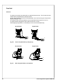
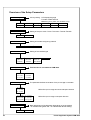
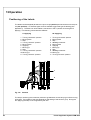
13 Operation
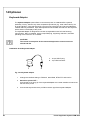
Positioning of the Labels
The labels could be applied parallel to the print line (0°-position) as well as across to the print
line (90°-position). An external signal via PLC interface triggers the type of labelling (see
appendix C). The take-over of the labels is carried out in the 0°-position for both types of
applying. The following movements are different :
90°-Applying
0°-Applying
1.
2.
3.
4.
5.
6.
7.
8.
9.
10.
11.
Turning into the 90°-position
Moving down
Stop
Turning into the 0°-position
Moving down
Applying
Moving up
Stop
Turning into the 90°-position
Moving up
Turning into the 0°-position
1.
2.
3.
4.
5.
6.
7.
8.
9.
10.
11.
Turning into the 90°-position
Moving down
Stop
not any movement
Moving down
Applying
Moving up
Stop
not any movement
Moving up
Turning into the 0°-position
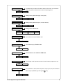
1
2
Fig. 13a
Sensors
The stop is set during the movement process to guarantee a correct carrying out of the turning
of the pad. The location of the stop depends on the setting of the sensors (1, 2). During the
90°-applying the stop is not recognized by the user.
44
Printer-Applicator-System PAM 3000
Switch on the Printer
NOTICE !
Check all external connections before starting to print.
Make sure that the media is loaded corresponding to the instructions.
Check that the transfer ribbon is loaded properly before starting to print.
CAUTION !
Make sure that the slide valve of the lift cylinder is closed during operation (see
chapter 5). Otherwise the lift cylinder can be moved without control. This fact can
cause damages.
NOTICE !
Make sure that the pad is not covered by a label when switching on the device.
1
2
Fig. 13b
Power supply
Switch on the compressed air supply.
Switch on the power supply (2) of the Printer-Applicator-System.
The printer carries out a short system test and following the display shows the system mode
"ONLINE". If a hardware failure occurs during the system test the type of the failure will be
shown. In this case the printer should be switched off and on again. If the failure occurs
again call for service.
If the display is not showing anything after switching on the printer, please check the following:
- the connection of the power cord is correct
- the fuse (1) that protects the power connection, is not defective
Printer-Applicator-System PAM 3000
45
Standard Operation
NOTICE !
Before starting the first print job after switching on the printer it is necessary to
synchronize the label feed :
Press the
manually.
key to generate a synchronous running. Remove the processed labels
Start the print job.
Start the labelling process via PLC interface.
With every start signal received by the PLC interface the printer performs one application
cycle.
Printhead is moved down.
Label is printed.
Printhead is moved up.
Pad is moved to the peel-off table, vacuum is switched on.
Label is peeled off by moving back the peel-off table and taken by the pad of the applicator
module.
Pad is driven to move back into the upper end position.
Peel-off table is driven to move back into the front position.
Label is transported into the labelling position, vacuum is switched off.
Label is placed onto the product.
Pad is driven to return in its upper end position.
Now the printer-applicator-system is ready for the next cycle.
If an error occurs while the printer-applicator-system is operating, this is shown in the display
(for types of errors and how to treat them see appendix A).
46
Printer-Applicator-System PAM 3000
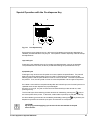
Special Operation with the Pre-dispense Key
1
Fig. 13c
Pre-dispense key
By pressing the pre-dispense key (1), half cycles of the labelling process can alternately be
released, provided that there is a print job. This operation mode is especially made for setups
and adjustments.
1(st) half cycle
Pressing the key releases the print of one label provided that there is a print job available.
The printhead is driven down, a label is printed and following the printhead is driven up.
2(nd) half cycle
Pressing the key will drive the lift cylinder to move the pad to the peel-off table. The peel-off
table is driven back and the label is put on the pad. Following the pad is moved into the
labelling position and the peel-off table is driven to move to the front. The label is placed onto
the product. Then, the lift cylinder is driven to move the pad back into the upper end position.
If the label is removed from the pad manually after the first half cycle, the first half cycle will be
repeated when the pre-dispense key is pressed again.
If there is no print job, only the movements of the second half cycle are carried out, when
pressing the key.
The first half cycle of the labelling process can also be released by pressing the
key on
the control panel of the printer. In that case, a blank label is picked up by the pad. That way,
the whole labelling process can be simulated by alternately pressing the
dispense key without the need of a print job or a connection to a computer.
key and the pre-
CAUTION !
By carrying out the applying cycle an area for the movements of the pad
has to be free.
Printer-Applicator-System PAM 3000
47
14 Optionen
Keyboard Adapter
The keyboard adapter option offers to connect the printer to a standard PC keyboard,
preferably "Cherry" brand or any other compatible input device (e.g. a bar code scanner) via
its serial interface. Using the keyboard, print jobs of an internal PC card may be loaded and
variable data may be altered. Input data requests as well as data received from the keyboard
will be shown in the display of the printer.
The keyboard adapter is designed for use with all keyboards which fulfill the following
requirements : MF-2 compatible, having a 5pin DIN plug, supporting code set 3, and also
operating with a maximum of 15 kBaud.
CAUTION !
The current consumption of the connected keyboard or scanner must not
exceed 100 mA.
Installation of the Keyboard Adapter
1 - 25 pin SUB-D plug
2 - 5 pin DIN connector
1
2
Fig. 14a Keyboard adapter
48
1.
Change the interface setting to "RS232C, 9600 Baud, RTS/CTS" and confirm.
2.
Switch the printer OFF !
Connect the 25 pin plug (1) of the keyboard adapter to the serial interface connector at
the side of the printer.
3.
Connect the keyboard to the 5 pin DIN connector (2) of the keyboard adapter.
Printer-Applicator-System PAM 3000
Key Assignment
The printer can easily be adjusted to the keyboard configuration of the particular country by
using the setup parameter "Country". For each of the available settings the printer has a
different table of key assignment, which, generally, complies with the assignment under
Microsoft DOS.
The [ALTGR] key has no function. Therefore, all signs which are located on the right hand
side of the key opposite of the normal characters (e.g. { } [ ] \) can be generated by pressing
the [ALT] key.
A few of the other special signs (e.g. ¨ × ÷) may also be generated the same way.
Other special characters (e.g. ñ ç ) can be generated by inserting two characters one after
the other, where the second input is a combination with the [ALT] key.
Some of the special characters cannot be shown in the display of the printer. In that case, the
PAM 3000 will use a character which looks similar to the required character.
NOTICE !
When using a scanner, the character set of the scanner has to be the same as
used by the printer.
Special Key Functions
[F1]
[á],[â]
[ENTER] or
[RETURN]
[Shift]+[Del]
[ESC]
[SPACE]
[F2]
[F3]
[Shift]+[F6]
[F7]
[F8]
To enter the list of labels stored on the memory card.
To scroll up/down the list of labels on the memory card.
Without a current print job : to switch between ONLINE and OFFLINE;
While processing a print job : to confirm the data input.
To delete the input line.
To cancel the data input. (while printing same effect as CANCEL)
While printing same effect as PAUSE.
To repeat the print of the last label. (as command A 1 CR)
To repeat the print of the last label including a new enquiry for variable data.
To start the self test printout.
Printer Info Display
Form feed
Printer-Applicator-System PAM 3000
49
Memory Cards
The printer provides an option for using memory cards to permanently save graphics, fonts,
complete label formats, or database information. Data transfer may be performed via
interface.
It is recommended that you make backup copies in case of malfunction of the original cards.
The printer is able to read from PCMCIA version 2.1 compatible sRAM cards or FlashEPROM cards. The maximum memory capacity is 4 MegaByte.
Preparing the Memory Card
1
2
3
Fig. 14b Write protection / Inserting the battery
The write protection of the card may be activated or deactivated by shifting the switch ( 1)
located at the front side of the card. The interpretation of the setting may be read from an
imprint (3) on the back of the card.
If you want to format the card or write on it, switch off the write protection.
For replacing or inserting the battery in sRAM cards refer to the instructions of the
manufacturer. In case the battery has to be replaced, it is usually found in a slot (2) above the
switch (1).
Installation of the Memory Card
3
1
4
2
Fig. 14c Installation of the memory card
Fig. 14d Connecting side
The front side of the memory card (1) is usually marked by the inscription "MEMORY CARD",
and an arrow (2) representing the direction of inserting the card into the drive. There is also
an arrow (4) impressed into the frame of the memory card slot of the printer.
Insert the card (1) into the slot (3) so that the front of the card faces the arrow (4).
At the connecting side of the card there are different guides on the top and the bottom which
make it impossible to insert the card incorrectly.
50
Printer-Applicator-System PAM 3000
Formatting the Memory Card
For operation, the memory card first has to be structured internally in a certain way. Normally,
memory cards are already pre-formatted in a suitable manner.
If the card you are using is not formatted at all, the printer will bring up one of the messages
"Unknown card" or "Structural err.". Then, you may format the card using one of the following
methods :
1. Formatting the card using the printer setup command "Format card" (see chapter 10).
2. Formatting the card using the printer interface and the printer command "Mf;name CR".
Writing on the Memory Card
There are also different methods to write onto a memory card.
The easiest way is to write on the card using the card drive of the printer and transfer the data
via interface.
For saving a label, you need to put the label design commands into "brackets" consisting of
"Ms"-commands :
Ms LBL;ABC
Command to save a file called "ABC"
J
|
H 100,0,T
|
S l1;0,0,68,71,106
|
Contents of the file "ABC"
T 10,10,0,3,pt15;Memory card
|
A 1[NOPRINT]
|
Ms LBL
End of Save File command
After completing the commands the file "ABC" is stored on the card with all commands from
"J" to "A" which describe the label format.
The parameter [NOPRINT] used within the command A line will suppress the print of the label
while saving the file.
Whenever the file "ABC" is called up, exactly one label will be printed.
If you want to print the label in a variable quantity do not use the A command within the label
description.
Printer-Applicator-System PAM 3000
51
Printing from a Memory Card
NOTICE !
Using a memory card provides the opportunity to print without a connection of
the printer to a computer.
Follow the instructions below, after the card has been installed and the printer has
been switched ON :
1.
Switch printer into OFFLINE mode by pressing the
2.
After pressing the
key.
key, the file name of the first label saved on the card will be
shown.
3.
Using the
key and the
key, you may scroll up and down the contents of the
card. Confirm the selection by pressing the
key.
4.
If you have chosen a label with a set number of labels to print, the printer will instantly
start printing.
5.
For labels with a variable number of labels, the top line of the display shows "Number
of labels", the bottom line shows "00001" with the first figure flashing (cursor).
Using the
key and the
altered. By pressing the
key, the figure at the position of the cursor may be
key the cursor can be moved on to the next figure. After
confirming of the last figure, the printer starts to print.
6.
To pause the selection of a label or the input of the number of labels you may press
the
key.
The data saved on the card are also accessible via interface and computer.
52
Printer-Applicator-System PAM 3000
Warning Light
By using the warning light it is possible to recognize the state of the printer with one view.
1
3
2
Fig. 14e Connection of the warning light
It is recommended to fix the warning light (1) at a bracket or a plate. For that purpose there
are a plate and suitable screws included in the delivery contents of the light.
The warning light has to contact to the printer by inserting the connection cable (2) of the
warning light into the 4-pin connector (3).
During the operation the lamps have following functions :
green
Device is switched on, voltage is available.
yellow
Warning : labels respectively transfer ribbon have passed the
preset minimum quantity.
Function is only available when the warning sensor label end
is mounted.
red
Printer error
Further information about the kind of error is shown on the display.
Printer-Applicator-System PAM 3000
53
Warning Sensors
The sensors recognize, when the diameter of the label supply roll respectively the transfer
ribbon roll decreases below a preset threshold value.
NOTICE !
The messages of the sensors are only intended to inform the operator. They do
not influence the operation of the printer, i.e. the operation is not interrupted.
The messages will be shown by switching on the yellow lamp of the warning light (option).
The signals also can be sent to a control system by using the peripheral interface.
Warning Sensor Label End
1
2
3
4
5
6
7
8
9
10
Fig. 14f Warning sensor label end
Mounting
1.
2.
3.
4.
Switch off the printer
Slide the sensor holder (1) with the warning sensor label end (2) behind the wind plate
(5) of the media supply hub.
Attach the sensor holder with the slotted head screw (7) and the hexagon socket head
screw (3) to the mounting plate. The hexagon socket head screw (3) must be used at
this side, where the elongated hole is located in the sensor holder.
Plug the cable (4) into the 5-pin connector (10) at the side of the frame of the printer.
Adjustment
With this setting the threshold diameter (84 to 110mm) for the warning message can be
adjusted.
1.
2.
3.
4.
5.
54
Slide a label roll (9) with the intended threshold diameter onto the media supply hub.
Switch on the printer. The sensor (2) sends out a beam (6). If the label roll does not
interrupt the path of the beam, the beam is mirrored at the reflective foil (8) and
detected again by the sensor. In that case the LED at the sensor is on.
Loosen the hexagon socket head screw (3) and swing the sensor holder against the
axle of the media supply hub as near as possible. The LED at the sensor is off.
Slowly swing the sensor holder away from the axle until the LED at the sensor goes on.
Tighten the hexagon socket head screw (3).
Printer-Applicator-System PAM 3000
Warning Sensor Ribbon End
NOTICE !
The warning sensor ribbon end is only analyzed by the printer electronics if the
warning sensor label end is also installed.
1
2
3
4
4
9
15
15
5
6
20
7
8
7
8
Fig. 14g Warning sensor ribbon end
Mounting
1.
2.
3.
4.
Switch off the printer
Attach the sensor holder (2) with the warning sensor ribbon end (3) to the mounting
plate using the screws (1).
Plug the cable (4). For that the printer has a 3-pin connector at the side of the frame.
The contents of delivery include a reflective foil (7).
Remove the covering foil from the glued surface and stick the reflective foil (7) onto the
brake (8) below the ribbon hubs as shown in fig.14g. Make sure that the distance
between the reflective foil and the mounting plate (9) is about 15 mm.
Adjustment
With this setting the threshold diameter 34 to 41 mm for the warning message can be
adjusted.
1.
2.
3.
4.
5.
Slide a transfer ribbon roll (6) with the intended threshold diameter onto the media
supply hub.
Switch on the printer. The sensor (3) sends out a beam (5). If the ribbon roll does not
interrupt the path of the beam, the beam is mirrored at the reflective foil (7) and
detected again by the sensor. In that case the LED at the sensor is on.
Loosen the screws (1) and move the sensor holder to the right as far as possible.
The LED at the sensor is off.
Slowly move back the sensor holder to the left until the LED at the sensor goes on.
Tighten the screws (1).
Printer-Applicator-System PAM 3000
55
Service Unit
It is very important for operating with the PAM 3000 System to guarantee a constant pressure
of the compressed air and to use only filtered compressed air. Therefore it is recommended
to use a service unit to adjust and to filter the air.
Two variations of service units are offered. The first variation is only to use for filtering and
adjusting the compressed air. The second variation is additionally equipped with a start-up
valve. This valve guarantees a soft flow of compressed air into the system.
A connector for the compressed air supply (1) is located at both variations of service units.
The connector is suitable for a 1/4" coupling plug.
1
1
2 2
2 2
3
3
Fig. 14h
Service unit - variation 1
Fig. 14i Service unit - variation 2
4 4
5
Fig. 14k
Mounting the service unit
It is recommended to fix the service unit at the mounting plate of the printer. For that purpose
there are two holes (4) in the mounting plate and two holes (2) in the plate of the service unit.
The service unit can be mounted at the plate using the two screws included in its delivery
contents.
Following the service unit has to connect to the printer (5) at one side (3) and to the
compressed air supply at the other side (1).
56
Printer-Applicator-System PAM 3000
Antistatic Brush
Using the antistatic brush it is possible to reduce the electrical charge in the print area.
3
3
2
3
1
Fig. 14l
Antistatic brush
It is very easy to fix the brush.
The antistatic brush has only to put off with its clamps (3) on the axle (1). The direction of
putting off is shown in the figure above. Adjust the brush so that the bristles slightly touche the
transfer ribbon (2).
Printer-Applicator-System PAM 3000
57
This page is intentionally left blank.
58
Printer-Applicator-System PAM 3000
Appendix A - Error Messages / Problem Solution
Error Messages
The PAM-System is equipped with a comprehensive self diagnostic system which will indicate
errors in the display of the printer. Also, the operator will be informed by the LEDs whether the
fault is correctable and will, therefore, allow to continue the current print job after corrections
(e.g. "Out of paper"), or the fault may require you to cancel the current print job.
Correctable Errors
While processing a print job, an error has occured which may be corrected by the operator,
and also allows you to continue the print job after fault correction.
Display
The display shows alternately the type of fault and the total of the remaining labels of the
current print job.
LED Display
LED CAN on, LED PSE is flashing.
Function Keys
CAN key
PSE key
short pressing :
Cancels the current print job,
Switch to the next job in the input buffer
longer pressing (>1s):
Cancels the current print job,
Deletes the input buffer (LED CAN blinks),
Switch into ONLINE mode
Continues the current print job after error correction,
Switch into PRINT mode (LED PSE off)
Table A-1 Function keys in mode FAULT-CORRECTABE
Printer-Applicator-System PAM 3000
A-1
Irrecoverable Errors
During printing, a fault has occured which cannot be cleared by the operator without cancelling
the current print run (e.g. hardware fault).
Display
The type of fault is shown in the display.
LED Display
LED CAN is flashing.
Function Keys
CAN key
Cancels the current print job.
Switch into ONLINE mode.
(LED ONL on, LED CAN off, LED PSE off)
If ONLINE mode cannot be entered, switch printer on and off again.
If the fault remains again, call for Service
Table A-2 Function keys in mode FAULT-IRRECOVERABLE
Errors During System Test
When switched on the printer automatically performs an internal self test.
If the test is completed succesfully, the PAM 3000 proceeds into the ONLINE mode.
If a hardware-fault occurs, the type of error is shown. In this case switch printer off and on
again.
If the fault remains again, call for Service.
A-2
Printer-Applicator-System PAM 3000
List of Error Messages
The following table contains an overview of possible error messages, their possible causes
as well as solutions to the problems.
Correctable faults as defined above are marked with a " * ".
If the suggested solutions turn out unsuccessful, call for Service.
Error message
Possible cause
Solution
ADC malfunction
Hardware error
Switch printer off and then on
If error recurs ® contact Service
Buffer overflow
The data receive buffer is full but the
computer is still transmitting data.
Use the protocol (preferably RTS /
CTS) for data transmission
Card full
Refers to the optional memory card;
No more data can be stored on the card
Replace the card
dRAM
malfunction
Hardware error
Switch printer off and then on
If error recurs ® contact Service
File not found
Requested file is not on the card.
Check the contents of the card
FPGA
malfunction
Hardware error
Switch printer off and then on
If error recurs ® contact Service
Head above
Printhead is not in its upper position.
Check the printer for proper
operation of its mechanics and
pneumatics;
Call for service;
Head below
Printhead is not in its lower position.
Check the printer for proper
operation of its mechanics and
pneumatics;
Call for service;
Head too hot *
Printhead is overheated due to labels
containing a lot of graphics, text, bar codes,
etc.
After pausing to cool down the
printhead, the print job will be continued automatically.
If the fault recurs repeatedly, reduce
the heat level or the print speed via
the software.
Host stop/ error *
Operation has been interrupted by a signal
of an external control
Label the product manually if
necessary
Release the signal
Invalid data
Fault while downloading graphic data
Cancel current print job
Check data
Invalid outline
Error with the selected font
(download font)
Cancel current print job
Change font
Invalid setup
Setup is invalid
Use RESTORE function to reset all
settings back to factory settings
Configure setup
If error recurs ® contact Service
Table A-3 Error messages
Printer-Applicator-System PAM 3000
A-3
Error message
Possible cause
Solution
Label not depos.
Label has not been placed onto the product;
after cylinder has moved back the label still
sticks on the vacuum plate of the pad
Label the product manually
LCD malfunction
Hardware error
Switch printer off and then on
If error recurs ® contact Service
Lower position
Pad has not reached the labelling position
within 2s after the movement of the cylinder
Check the applicator for proper
operation of its mechanics;
Check the labelling position sensor
(service);
Label the product manually (service)
Memory overflow
Current print job contains too much
information (selected fonts, large graphics)
Check the contents of the card
No label found *
There are labels missing on the label
material
Press
The label format as set in the software does
not correspond with the real label format
Cancel current print job
Change the label format set in the
software; Restart print job
Printer is loaded with continuous paper but
the software is set on labels
Cancel current print job
Change either software setting or
print media; Restart print job
No label size
Definition of the label size is missing at the
label description
Check programming
No record found
No database record has been found
when using optional memory card
Check programming and/or database
for record in question
Out of paper *
Out of label material
Insert new supply roll
Label has not properly been loaded
Check paper feed
Out of transfer ribbon
Load new supply roll of transfer
ribbon.
Ribbon melted during printing
Cancel the current print job.
Change the heat level via software,
clean the printhead, load transfer
ribbon, restart print job.
Out of ribbon *
key repeatedly until
printer recognizes the next label on
the material.
The printer is loaded with thermal labels for Cancel current print job
direct thermal mode (without transfer ribbon); Set software to direct thermal mode
Restart print job
but the software is set for transfer printing.
The supply roll of transfer ribbon is turning
on the supply hub.
Tighten the supply roll of transfer
ribbon by turning the knurled knob at
the supply hub.
Table A-3 Error messages (continuation)
A-4
Printer-Applicator-System PAM 3000
Error message
Possible cause
Solution
Pad 0° error
Pad has not reached the 0°-position.
Check the applicator for proper
operation of its mechanics and
pneumatics; Check the sensor;
Call for Service.
Pad 90° error
Pad has not reached the 90°-position.
Check the applicator for proper
operation of its mechanics and
pneumatics; Check the sensor;
Call for Service.
Protocol error (*)
The interfaces of computer and printer are
set differently.
Switch printer off
Correct the interface setting in the
printer setup.
Printer has received an unknown or invalid
command (display shows command
abbreviated)
Depending on the type of fault, the
command can be skipped by
pressing the
key or the print job
has to be cancelled by pressing the
key.
Read error
Error when reading from the optional
memory card
Check the data on the memory card.
Save the data to another card and
reformat the original card.
ROM malfunction
Hardware error
Switch printer off and then on
If error recurs ® contact Service
Scan result negative
The bar code is not correct.
Check the path of transfer ribbon and
media.
Check the printer for proper
operation of its mechanics and
pneumatics;
Call for service;
Structural error
The optional memory card file structure is
not compatible.
Format the memory card.
Table not at the back
The table has not reached its behind
position.
Check the printer for proper
operation of its mechanics and
pneumatics;
Call for service;
Table not in front
The table has not reached its front position.
Check the printer for proper
operation of its mechanics and
pneumatics;
Call for service;
Unknown card
The optional memory card is not formatted,
or the type is not supported by the printer.
Format the memory card. Use the
correct type of card as specified in
the Memory card section
Table A-3 Error messages (continuation)
Printer-Applicator-System PAM 3000
A-5
Error message
Possible cause
Solution
Upper position
Pad has not reached the upper position
within 2s after the lift cylinder has moved
back;
Pad has left the starting position
unauthorized;
Check the applicator for proper
operation of its mechanics;
Check if the slide valve is closed;
Label the product manually;
(Service)
Vac. plate empty
Label has not been picked up properly by the If possible place the 'lost' label onto
pad; or Label fell off the pad before it could
the product manually;
be placed onto the product
Otherwise stop print job and start
again with adapted parameters (e.g.
count)
Voltage error
Hardware error
Switch printer off and then on
If error recurs ® contact Service
Write error
The optional memory card has encountered
a hardware error.
Repeat the write process or reformat
the memory card.
Write protected
Refers to the optional memory card.
Write protection is activated.
Deactivate write protection.
Table A-3 Error messages (continuation)
A-6
Printer-Applicator-System PAM 3000
Problem Solution
Problem
Cause and Solution
Print image has smears or voids
Printhead is dirty, Clean printhead
Temperature too high;
Decrease heat level via software
Unsuitable combination of ribbon and label media;
Choose different type of ribbon
Print image is irregular,
one side is lighter
Printhead is dirty, Clean printhead
Vertical white
lines in the print image
Printhead is dirty, Clean printhead
Printer does not display
error message: "Paper out"
Label is not inserted in the label edge sensor
Correct the label path
Printhead is not correct adjusted,
Adjust printhead (service)
Printhead is defective (failure of heat elements),
Replace printhead (service)
Label strip is not guided over the swing arm
Correct the label path
Printer transports label media, but
the ribbon does not move
Transfer ribbon is wrong inserted. Check, if the inked side faces the
label
The combination of ribbon and media is unsuitable
Choose different type of ribbon
Thermal transfer ribbon
creases
Transfer ribbon too wide. Use transfer ribbon which is max. 10%
wider than the label media.
Printer does not stop after
transfer ribbon runs out
Direct thermal printing is chosen in the software
Change to thermal transfer printing
Error message "Ribbon out", though
ribbon is loaded
Transfer ribbon is not locked at the supply hub,
Supply hub does not turn,
Tighten the ribbon
Printer only prints each second label
Setting of the size in the software is too large.
Correct the setting
Loss of all applicator functions
Loss of compressed air; check all connections;
No I/O function
Check if ports of printer and computer are configured identically
Configure ports if necessary.
Check interface cable
Replace bad I/O cable.
Table A-4 Problem solution
Printer-Applicator-System PAM 3000
A-7
This page is intentionally left blank.
A-8
Printer-Applicator-System PAM 3000
Appendix B - Maintenance / Cleaning
General
The printer PAM 3000 only requires a minimum of maintenance.
It is most important to clean the printhead on a regular basis. This will guarantee a permanent
high quality of the print image. Moreover, it helps to prevent an early wear of the printhead.
Apart from that, the servicing only requires you to clean the outside of the printer
occassionally.
Cleaning the Printhead
While operating, dirt such as paper dust or particles of ink or back coating from the ribbon
may accumulate on the thermal printhead. This can cause a deterioriation of the print quality
(e.g. different contrasts on the label, appearance of light horizontal lines, etc.).
In that case, the printhead needs cleaning.
WARNING !
Disconnect power supply !
Switch off compressed air !
Recommended cleaning intervalls :
Direct Thermal Printing
: at every 1200 m
Thermal Transfer Printing : each time you change the ribbon
CAUTION !
Do not use any sharp objects for cleaning the printhead !
Do not touch the protective glass layer of the printhead !
Clean the printhead as follows :
Remove label material and transfer ribbon from the printer.
Clean the printhead surface with a special cleaning pen, or use a cotton swab soaked with
isopropyl alcohol.
Allow it to dry for about 2 to 3 minutes before restarting the printer.
1
Fig. B-1
Cleaning the printhead
Printer-Applicator-System PAM 3000
B-1
This page is intentionally left blank.
B-2
Printer-Applicator-System PAM 3000
Appendix C - Pin Assignment of the Interface Connectors
Pin Assignment of the Serial Interface Connectors
PAM 3000 provides a 25 pin SUB-D connector for the serial interfaces which are internally
available, i.e. RS-232, RS-422 and RS-485.
PIN 13
PIN 1
PIN 25
PIN 14
Fig. C-1 Connector of the serial interface (side of the printer)
Pin
Signal
Function
1
2
3
4
5
7
9
10
18
19
20
CG
TxD
RxD
RTS
CTS
GND
TDATA+
TDATARDATA+
RDATADTR
Protective Ground
Transmit Data (RS-232)
Receive Data (RS-232)
Request to send
Clear to send
Logic Ground
Transmit Data (RS-422, RS-485)
Transmit Data (RS-422, RS-485)
Receive Data (RS-422, RS-485)
Receive Data (RS-422, RS-485)
Data Terminal Ready
Table C-1 Signals of the serial interface connector
Following some typical RS-232 interface cable configurations are shown. Note, that the pin
assignment may vary for different computers. If you have any problems with the connections,
contact the manufacturer of your computer on the pin assignment of the interface. Use the
pin assignment of the printer as shown in table C-1 to obtain a suitable cable.
Fig. C-2
PC
Printer
1
2
3
5
7
6
8
20
1
3
2
20
7
4
5
25 pin connector
25 pin plug
Interface cable with 25 pin computer connector for RS-232 with protocol
" ---" or "XON/XOFF"
Printer-Applicator-System PAM 3000
C-1
Fig. C-3
Fig. C-4
Fig. C-5
PC
Printer
2
3
5
8
1
4
6
2
3
7
20
4
5
9 pin connector
25 pin plug
Interface cable with 9 pin computer connector for RS-232 with protocol
" ---" or "XON/XOFF"
PC
Printer
1
2
3
4
5
7
6
8
20
1
3
2
5
4
7
25 pin connector
25 pin plug
Interface cable with 25 pin computer connector for RS-232 with protocol
"RTS/CTS" or "XON/XOFF"
PC
Printer
2
3
5
7
8
1
4
6
2
3
7
5
4
9 pin connector
25 pin plug
Interface cable with 9 pin computer connector for RS-232 with protocol
"RTS/CTS" or "XON/XOFF"
Interface Cable for RS-422 / RS-485
To control the printer by RS-422/ RS-485 interface, only the signals TDATA+, TDATA-,
RDATA+, and RDATA- are necessary.
Check the pin assignment for the interface of your computer, and use the pin assignment of
the printer as shown in table C-1 to obtain a suitable cable. The connectors of TDATA+ and
RDATA+ as well as TDATA- and RDATA- at the plug-in-connection of the cable must be
united. If there is a very large transfer distance a termination of the cables is recommended.
C-2
Printer-Applicator-System PAM 3000
Pin Assignment of the Parallel Interface Connector
The printer provides a 36 pin connector for the parallel Centronics interface.
PIN 18
PIN 1
PIN 36
PIN 19
Fig. C-6 Centronics interface connector (side of the printer)
Pin
1
2
3
4
5
6
7
8
9
Signal
Pin
Signal
Pin
Signal
Pin
Signal
/STROBE
DATA 1
DATA 2
DATA 3
DATA 4
DATA 5
DATA 6
DATA 7
DATA 8
10
11
12
13
14
15
16
17
18
/ACKNLG
BUSY
PE
SLCT
nc
nc
GND
nc
nc
19
20
21
22
23
24
25
26
27
GND
GND
GND
GND
GND
GND
GND
GND
GND
28
29
30
31
32
33
34
35
36
GND
GND
GND
nc
nc
nc
nc
nc
nc
Table C-2 Signals of the Centronics interface
Centronics Interface Cable
The cables used for Centronics interface connectors are standard cables, so that normally
there are no problems with the external control of the printer.
In the event of any difficulties, consult the manufacturer of your computer on the pin
assignment of the computer's interface. Use the pin assignment of the printer as shown in
table C-2 to obtain a suitable cable.
Printer-Applicator-System PAM 3000
C-3
PLC Interface Port
Pin Assignment of the PLC Interface
For use in a network the Printer-Applicator-System is equipped with a PLC interface to start
and interrupt the printing and labelling process. It also passes on state information as well as
error messages of the Printer-Applicator-System to the control of the network.
The interface has a 25 pin SUB-D connector (1).
PIN 1
PIN 13
1
PIN 14
PIN 25
Fig. C-7 Connector of the PLC-interface (side of the printer)
Pin
Signal
1
2
3
4
5
6
7
8
9
10
11
12
13
14
15
16
17
18
19
20
21
22
23
24
25
n.c.
n.c.
XDKO
XDNB
XEPOS
XESP
RUEL
XEDG
EXF
EUEB
STRT
DRW
ESP
n.c.
XTIV
XVW
XEDST
XRTA
n.c.
n.c.
EXFR
EUEBR
STARTR
DRWR
ESPR
Direction
Function
variation without applicator variation with applicator
output
output
output
output
(output)
output
input
input
input
input
input
Printhead position
Printer not ready
Label is printed
Label is dispensed
revers line (for all outputs)
No existing print job
External error
Label is taken
Start signal
Print repeat
Label dispense
Printhead position
Printer, applicator not ready
Pad in labelling position
Applying process is ready
Revers line (for all outputs)
No existing print job
External error
Recycle part in position
Start signal
GoodRead (Scan result)
90°-labelling
output
output
output
output
Position of the peel-off table
Warning end of material
Print of label has started
without function
Position of the peel-off table
Warning end of material
Pad in starting position
Activate the recycle part
(input)
(input)
(input)
(input)
(input)
External error (revers line)
Label is taken (revers line)
Start signal (revers line)
Print repeat (revers line)
Label dispense (revers line)
External error (revers line)
Recycle part pos. (revers line)
Start signal (revers line)
Not connect
90°-labelling (revers line)
Table C-3 Pin assignment of the PLC interface
C-4
Printer-Applicator-System PAM 3000
Circuit Diagram of Inputs and Outputs
The inputs are optocouplers with a current limiting resistor of 2.2kW giving a voltage of 24V in
the input circuit.
X[IN]
X[IN]R
Fig. C-8
Circuit of the inputs
For each signal X[IN] there is a separate reverse line X[IN]R via plug connector. From
that the following pairs of signals result :
X[IN]
Pin
X[IN]R
Pin
EXF
EUEB
STRT
DRW
ESP
9
10
11
12
13
EXFR
EUEBR
STARTR
DRWR
ESPR
21
22
23
24
25
Table C-4 Input pairs of signals
All outputs are recognized through solid state relays. Their outputs are connected to one
another on one-side. The joint line is lead to the plug connector as a RÜL signal.
The switch function of the outputs is to open or close the contact between the joint line RÜL
and the respective output.
Electrical requirements :
Umax = 42V
Imax = 100mA
X[OUT]
RÜL
Fig. C-9
Circuit of the ouputs
Printer-Applicator-System PAM 3000
C-5
Explanation of the Signals
XDKO - Printhead position - both variations
The signal is necessary to recognize whether the printhead is in its upper or lower position.
XDKO is active if the printhead is in its upper position.
In this state the contact between PIN3 and RÜL (PIN7) is opened.
XDNB - Printer not ready - variation without applicator
An error has occured on the printer.
The label print is stopped and the details and type of error can be read from the printer display
('Ribbon out'; 'Paper out'; 'No label').
After the error is corrected, it is possible to press the
key and the print job will be
continued. The last label printed before the error occured will be repeated.
Pressing the
key will stop the print job and reset the printer.
XDNB is active if the contact between PIN4 and RÜL (PIN7) is opened.
XDNB - Printer, applicator not ready - variation with applicator
An error has occured on the printer-applicator-system.
The label print and apply is stopped and the details and type of error can be read from the
printer display ('Ribbon out'; 'Paper out'; 'No label').
After the error is corrected, it is possible to press the
key and the print job will be
continued. The last label printed before the error occured will be repeated.
Pressing the
key will stop the print job and reset the printer.
XDNB is active if the contact between PIN4 and RÜL (PIN7) is opened.
XEPOS - Label is printed - variation without applicator
It is indicated that a label is printed.
XEPOS is active if the contact between PIN5 and RÜL (PIN7) is closed.
XEPOS - Pad in labelling position - variation with applicator
The pad has reached the labelling position.
XEPOS is active if the contact between PIN5 and RÜL (PIN7) is closed.
XESP - Label is dispensed - variation without applicator
It is indicated that the peel-off table is fed back and that way the label is taken.
XESP is active if the contact between PIN6 and RÜL (PIN7) is closed.
XESP - Applying process is ready - variation with applicator
The applying process is completed successfully.
XESP is active if the contact between PIN6 and RÜL (PIN7) is closed.
XEDG - No existing print job - both variations
There is no print job currently available.
In this state the contact between PIN8 and RÜL (PIN7) is opened.
EXF - External error - both variations
An error has occured on the external device.
The label print is stopped and the display of the printer shows the message "External error".
After the error is corrected, it is possible to press the
key and the print job will continue.
The last label printed before the error occured will be repeated.
C-6
Printer-Applicator-System PAM 3000
Pressing the
key will stop the print job and the printer will be reset.
EXF is active when current flows between PIN9 and PIN21.
EUEB - Label is taken - variation without applicator
The label is taken from the dispense position. EUEB is active when current flows between
PIN10 and PIN22.
EUEB - Recycle part in position - variation with applicator
The recycle part is in the position to take-over the labels. EUEB is active when current flows
between PIN10 and PIN22.
STRT - Start signal - both variations
The STRT signal triggers the start of the print with an impulse of 20 ms.
XSTART is active when current flows between PIN11 and PIN23.
DRW - Print repeat - variation without applicator
The print of the last label should be repeated. DRW is active when current flows between
PIN12 and PIN24.
DRW - GoodRead (Scan result) - variation with applicator
The signal indicates the good result of scanning.
DRW is active when current flows between PIN12 and PIN24.
ESP - Label dispense - variation without applicator
The label should be dispensed. ESP is active when current flows between PIN13 and PIN25.
ESP - 90°-labelling - variation with applicator
The label should be applied in the 90°-position. ESP is active when current flows between
PIN13 and PIN25.
XTIV - Position of the peel-off table - both variations
The signal is necessary to recognize whether the peel-off table is in its front or back position.
XTIV is active if the peel-off table is in its back position.
In this state the contact between PIN15 and RÜL (PIN7) is opened.
XVW - Warning end of material - both variations
This signal reports that there is only still a few amount of material (ribbon or label media)
available. The user has to check the warning sensors ribbon end and label end.
In this state the contact between PIN16 and RÜL (PIN7) is opened.
XEDST - Print of label has started - variation without applicator
It is indicated that the print of a label has started.
XEDST is active if the contact between PIN17 and RÜL (PIN7) is closed.
XEDST - Pad in starting position - variation with applicator
The pad has reached the starting position.
XEDST is active if the contact between PIN17 and RÜL (PIN7) is closed.
XRTA - Activate the recycle part - variation with applicator
The recycle part for the bad labels should be activated.
XRTA is active if the contact between PIN18 and RÜL (PIN7) is closed.
Printer-Applicator-System PAM 3000
C-7
Scanner Connector
Pin Assignment
The printer provides a 9 pin port to connect a scanner. The scanner connector is only
supported at variations with applicator.
PIN 5
PIN 1
PIN 9 PIN 6
Fig. C-10 Connector of the scanner (right side of the printer)
Pin
Signal
1
2
3
6
7
8
GND
DRW
XSCA
24P
DRWR
XSCAR
Direction
input
output
(input)
(output)
Function
Ground
GoodRead (Scan result)
TopScan
Operating voltage +24V, Si T 100mA
GoodRead (revers line)
TopScan (revers line)
Table C-5 Signals of the scanner connector
Circuit Diagram of Input and Output
The input is an optocoupler with a current limiting resistor of 2.2kW giving a voltage of 24V
in the input circuit.
PIN 2 - DRW
PIN 7 - DRWR
Fig. C-11 Circuit of the input
C-8
Printer-Applicator-System PAM 3000
The output is recognized through solid state relays. The line is lead to the plug connector as
a RÜL signal.
The switch function of the output is to open or close the contact between the line RÜL and the
output.
Electrical requirements :
Umax = 42V
Imax = 100mA
PIN3 - XSCA
PIN8 - XSCAR
Fig. C-12 Circuit of the ouput
Explanation of the Signals
GND - Ground (0V)
DRW - GoodRead
The signal indicates the good result of scanning.
DRW is active when current flows between PIN2 and PIN7.
XSCA - TopScan
The printed label should be scanned.
In this state the contact between PIN3 and RÜL (PIN8) is closed.
24P - Operating voltage +24V, Si T 100mA
Example of a Circuit Diagram for a Connector
If there is no scanner connected it is necessary to simulate the goodread-signal. This can
be realized by a connector. In the figure below you can find an example for the circuit diagram
of this connector.
PIN2
PIN7
+24
GND
PIN6
PIN1
Fig. C-13 Circuit diagram of a connector to realize the goodread-signal
Printer-Applicator-System PAM 3000
C-9
This page is intentionally left blank.
C-10
Printer-Applicator-System PAM 3000
Appendix D - Setup Selectable Character Tables
Table D-1 Character Set "Windows 1252"
Table D-2 Character Set "Windows 1250"
Printer-Applicator-System PAM 3000
D-1
Table D-3 Character Set "ISO 8859-1"
Table D-4 Character Set "Codepage 850"
D-2
Printer-Applicator-System PAM 3000
Table D-5 Character Set "EBCDIC"
Table D-6 Character Set "Macintosh"
Printer-Applicator-System PAM 3000
D-3
Table D-7 Character Set "Codepage 852"
Table D-8 Character Set "ISO 8859-8"
D-4
Printer-Applicator-System PAM 3000
Appendix E - Recommended Spare and Wearing Parts
Part.-No.
Description
Printer
Applicator
5945001
5945202
5521552
Spring
x
5521553
Wall Spacer
x
5521555
Shell 123 mm, D25.4
x
5521560
Rewinder End Cap
x
5521561
Shell 122.3 mm, D40
x
5521564
Rewinder Wall Plate
x
5530552
Plate
x
5530570
PCB Control Panel
x
5530571
LCD Display
x
5530823
Motor
x
5537543
Transport Locking Roller
x
5560434
Printhead NM3004-UA21B
x
5905395
Swing Drive CRB1BW30-270 S
5945056
Pinch Roller
x
5945066
Print Roller PAM 3000
x
5945120
Label Sensor Assy. PAM 3000
x
5945122
PCB Driver Electronics
x
5945124
Feed Roller PAM 3000
x
5945132
PCB Valve Connection
x
5945165
PCB Applicator Control
x
5945166
PCB CPU
x
5945225
Pad Holder Type 1200
x
5945232
Sensor Lift Cylinder 1
x
5945233
Sensor Lift Cylinder 2
x
5945236
Sensor Turn Cylinder
x
5945237
Labelling Position Sensor
x
5945242
Pad Holder Type 1100
x
5945244
Cover
x
Printer-Applicator-System PAM 3000
x
E-1
This page is intentionally left blank.
E-2
Printer-Applicator-System PAM 3000
Index
0°- Position 8, 46
90°-Position 8, 21, 46, C-4, C-7
A
ADC malfunction A-3
Adjustments 31ff.
Air connection 25
Air pressure 10, 25, 56
Antistatic brush 11, 57
Applicator module 8, 19ff., 46
B
Bar codes 9
Blow tube 22, 24, 32
Buffer overflow A-3
C
CAN key 35ff.
Card full A-3
Character set 39, D-1ff.
Cleaning, general B-1
Codepage 850 (Character set) D-2
Codepage 852 (Character set) D-4
Connections 25f
Connection to Power Supply 27
Control Panel 10, 39
Correctable Error A-1
Country 38
Cylinder 19, 21, 31
D
Date 39
Debug mode 39
Delivery Contents 15
Dimensions 10
DIP switches 18, 33
Direct Thermal Printing 12
Display 35
Documentation -further 7
dRAM malfunction A-3
E
EBCDIC (Character set) D-3
Error messages A-1ff.
External error C-4, C-6
F
FF key 35ff.
Fonts 9
FPGA malfunction A-3
Function Keys 35f
Fuse 37, 47
Printer-Applicator-System PAM 3000
G
Gap Sensor 10, 38
Graphic Elements 9
Graphic File Type 9
H
Head above A-3
Head below A-3
Head too hot A-3
Heat Level 38
Host stop / error A-3
I
Interface 8ff., 18, 26, 38, 41f., 46, C-1ff.
Interface cable 11, C-1ff.
Interface Connections 26
Interface, serial 8ff., 11, 26, 38, 40, C-1ff.
Invalid Data A-3
Invalid Outline A-3
Invalid Setup A-3
Irrecoverable Error A-2
ISO 8859-1 (Character set) D-2
ISO 8859-8 (Character set) D-4
L
Label (Edge) Sensor 13, 17, 38, 41
Label formats 11, 13, 22f., 23
LABEL FROM CARD (System Mode) 36
Label dispense C-4, C-7
Label is printed C-4, C-6
Label is dispensed C-4, C-6
label is taken C-4, C-7
Labelling position 8, 46f., A-4f., C-4, C-6
Label not deposited A-4
Labels, loading 29
Label material 11
Label Media Specifications 13f.
LCD malfunction A-4
LED 35f.
Lift cylinder 8, 19, 21, 31f., 47
Lower position A-4
K
Keyboard adapter 11, 48
M
Macintosh (Character set) D-3
Media Supply Hub 16, 29, 54f.
Media loading 28ff.
Media Rewind Hub 16
Memory card 11, 39, 41, 48, 50ff.
Memory card slot 12
Memory overflow A-4
N
No existing print job C-4, C-6
No label found A-4
No label size A-4
No record found A-4
O
OFFLINE (System mode) 36
ONLINE (System mode) 35
ONL key 35ff.
Operating voltage 10, 27
Operation 25, 33, 44ff.
Operator's Manual 7
Optional features 11
Out of paper A-4
Out of ribbon A-4
P
Pad 8, 19, 21ff., 31f., 44ff. A-5
Parallel Interface Port 18, 26
Pause Reprint 39
PAUSE (System mode) 36
Peel-off table 8, 10, 17, 31, 46f.
PLC Interface 8, 10, 18, 26, 46, C-4ff.
Pneumatic Cylinder 8
Position of the peel-off table C-4, C-7
Power Connector 18, 27
Pre-dispense key 16, 47
Printer not ready C-3, C-6
Printer Info 39
Printer Info Display 40f.
Printer Module 8
Printhead 8f., 12, 17, 29f., A-3ff., C-4, C-6
Printhead, cleaning B-1
Printhead Position 38
Print Mechanism 16f.
Print Media 12ff.
Print of label has started C-4, C-7
Print repeat C-4, C-7
Print Roller 15
Print Speed 7
PRINT (System mode) 36
Print Width 7
Product Description 8ff.
Programming 7
Protocol 26,C-2
Protocol Error A-5
PSE key 35f.
S
Safety Instructions 15
Scanner 26, 50f.
Scanner connector 18, C-8
Scan result negative A-5
Serial Interface Port 18, 26
Service Manual 7
Service unit 11, 56
Setup 37ff.
SETUP (System mode) 37
Signals (Scanner) C-8f
Signals (PLC) C-4ff.
Starting position 8, C-4, C-7
Start signal C-4, C-7
Structural error A-5
System Modes 35ff.
System Test 10, 45, A-2
T
Table not at the back A-5
Table not in front A-5
Technical Specifications 9ff.
Thermal Transfer Printing 12
Trademarks 7
Transfer Print 38, 41
Transfer Ribbon 12, 14, 30, 55, 57
Transfer Ribbon Loading 30
Turn cylinder 8, 19
U
Unknown card A-5
Upper position A-6
V
Vacuum 23
Vacuum plate empty A-6
Voltage Error A-6
W
Warning end of material C-4, C-7
Warning light 11, 18, 53
Warning sensor 11, 18, 54ff.
Windows 1250 (Character set) D-1
Windows 1252 (Character set) D-1
Write error A-6
Write protected A-6
R
Read error A-5
RESTORE 37
Rewinder - internal 29
Ribbon Supply Hub 16, 30
RS-232 8, 9, 26, 38, 40, 48, C-1f
RS-422 9, 26, 38, C-1f.
RS-485 9, 26, 38, C-1f.
ROM malfunction A-5
Printer-Applicator-System PAM 3000
cab-Produkttechnik
Gesellschaft für Computerund Automationsbausteine mbH & Co KG
Wilhelm-Schickard-Straße 14
D-76131 Karlsruhe
EU - Conformity Declaration
We declare herewith that as a result of the manner in which the machine designated below was designed, the
type of construction and the machines which, as a result have been brought on to the general market comply
with the relevant fundamental regulations of the EU Rules for Safety and Health.
In the event of any alteration which has not been approved by us being made to any machine as designated
below, this statement shall thereby be made invalid.
Description:
Printer-Applicator-System
Type:
Brady PAM 3000
Applied EU Regulations and Norms:
- EC Machinery Regulations
- Machine Safety
98/37/EU
EN 292/2 :1995-06
- EC Low Voltage Regulations
- Data and Office Machine Safety
73/23/EEC
EN60950 :1992 + A1 :1993
+ A2 :1993
- EC Electromagnetic Compatibility Regulations
- Threshold values for the Interference
of Data Machines
- Limits for harmonic current emission
89/336/EEC
EN 55022 :1998
- Limits of voltage fluctuation and flicker
- Interference Resistance in both
Industrial and Small Plants
Signed for, and on behalf of, the Manufacturer :
cab Produkttechnik Sömmerda
Gesellschaft für Computerund Automationsbausteine mbH
99610 Sömmerda
Sömmerda, 10.09.01
Erwin Fascher
Managing Director
Printer-Applicator-System PAM 3000
EN 61000-3-2 :1995+A1 :1998
+A2 :1998+A14 :1999 :2000
EN 61000-3-3 :1995
EN 55024 :1998