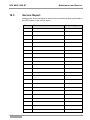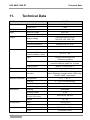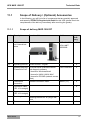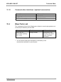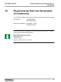
1
UPS Uninterrupted Power Supply MKD 1500 RT Operating Manual V. 1.0 Article number: MKD 1500 RT: ACX11MKT1K500000 Translation of the original operating manual UPS MKD 1500 RT Legal Notice Legal Notice by EFFEKTA Regeltechnik GmbH EFFEKTA Regeltechnik GmbH, 78628 Rottweil, retains the copyright to this documentation. This documentation is solely intended for the operator and his staff. The content of this documentation (texts, figures, drawings, graphics, plans, etc.) may not be copied or distributed in part or in full without our consent in writing, nor can it be used without authorisation for competitive purposes or given or made accessible to third parties. EFFEKTA Regeltechnik GmbH Rheinwaldstraße 34 D – 78628 Rottweil Phone: Fax: E-mail: Internet: + 49 (0) 74 1 / /1 74 51 - 0 + 49 (0) 74 1 / /1 74 51 - 22 [email protected] www.effekta.com Manual: Language: Release date: Operating manual English 04/2012 We reserve the right to make changes to the design and the system that will improve the system, the production process or the product MKD series 2 UPS MKD 1500 RT Table of Contents Table of Contents 1. Introduction ............................................................................................................. 5 1.1 Foreword ................................................................................................................... 5 1.2 Validity ...................................................................................................................... 6 1.3 Storage ..................................................................................................................... 6 1.4 Symbols in this Manual.............................................................................................. 6 1.5 Information Obligation ..............................................................................................10 1.6 Warranty Conditions .................................................................................................10 1.7 Transport and Storage..............................................................................................12 1.8 Positioning................................................................................................................13 2. Safety Instructions .................................................................................................14 2.1 Introduction ..............................................................................................................14 2.2 Proper Use ...............................................................................................................14 2.3 Avoiding Personal Injury / Property Damage ............................................................15 2.4 Protecting the Environment ......................................................................................15 2.5 Connection ...............................................................................................................16 2.6 Operation .................................................................................................................17 2.7 Handling Accumulators.............................................................................................17 2.8 Maintenance, Service and Malfunctions ...................................................................18 3. Device Description of UPS.....................................................................................19 3.1 Device Elements on the Front ..................................................................................20 3.2 Device Elements on the Back ...................................................................................23 3.3 Device modification ..................................................................................................28 4. Storage and Unpacking .........................................................................................37 4.1 Storage of the UPS ..................................................................................................37 4.2 Unpacking the Device...............................................................................................37 5. System Description ................................................................................................38 6. Installation and Connection of the UPS ................................................................40 6.1 Connection of the UPS .............................................................................................40 6.2 UPS communication connection ...............................................................................42 6.3 Connection Sequence ..............................................................................................43 7. Device and its Operation........................................................................................46 7.1 Operating the UPS ...................................................................................................46 7.2 Operating Manual for the UPS ..................................................................................51 7.3 Menu ........................................................................................................................55 8. Eliminating Errors ..................................................................................................64 9. Software ..................................................................................................................67 MKD series 3 UPS MKD 1500 RT 10. Table of Contents Maintenance and Service ...................................................................................... 68 10.1 Measurement of the Bridging Period (Support Period) ............................................. 68 10.2 Replacing the Accumulators .................................................................................... 69 10.3 Service Report ......................................................................................................... 70 10.4 Service Hotline......................................................................................................... 71 10.5 Maintenance and Service Contracts......................................................................... 71 11. Technical Data ....................................................................................................... 72 11.1 Scope of Delivery / (Optional) Accessories .............................................................. 73 11.2 Wear Parts List ........................................................................................................ 74 12. Requirements from the Declaration of Conformity .............................................. 75 MKD series 4 UPS MKD 1500 RT 1. Introduction 1.1 Foreword Introduction Dear Operator, You are about to operate an uninterrupted power supply. This operating manual should provide you with support for working responsibly and give you basic information about the uninterrupted power supply, namely how it operates, its application and what you should do in the event of malfunctioning. Furthermore, this operating manual contains instructions for the transport and storage as well as the handling and installation of the uninterrupted power supply. The plan guidelines in this operating manual only relate to special requirements for the uninterrupted power supply. During installation, make sure you follow the national and local requirements for electrical installations. The content of this device description may change due to technological progress. We have tried to present the content correctly and clearly. If, however, we have made errors, we would be grateful for information about this. We are not liable for errors in this operating manual and the resulting consequences. The uninterrupted power supply is intended to protect sensitive, electrical systems against interruptions that can occur due to poor power quality or mains failures. Please read this operating manual carefully and regard in particular the safety instructions! If you have questions about the device, our technical supervisor or our employees will be glad to help you. Your EFFEKTA Regeltechnik GmbH MKD series 5 UPS MKD 1500 RT 1.2 Introduction Validity The descriptions in this operating manual relate solely to the Uninterrupted Power Supply defined in the Technical Data as a whole or they refer to modules, components and individual parts that were developed and built by EFFEKTA Regeltechnik GmbH. 11. Technical Data 1.3 Storage This operating manual for the device must be stored in the vicinity of the device at all times so it is immediately available if need be. 1.4 Symbols in this Manual The abbreviation UPS in this manual stands for the uninterrupted power supply. Read this documentation carefully and make yourself familiar with the product before using it. Store this operating manual in an easily accessible place to refer to it if necessary. Please pass this operating manual on to later users of the product. 1.4.1 Danger warning levels Text that is marked with DANGER! provides a warning about dangers. If accident prevention measures are not taken, these dangers may result in serious (irreversible) injuries or even death! MKD series 6 UPS MKD 1500 RT Introduction Text that is marked with WARNING! provides a warning about hazards. If accident prevention measures are not taken, these hazards may result in serious (irreversible) injuries or even death! Text that is marked with CAUTION! provides a warning about hazards. If accident prevention measures are not taken, these dangerous situations can lead to slight or medium reversible injuries. Text that is marked with ATTENTION! contains very important instructions for situations that, if accident prevention measures are not taken, may result in damage to the product and / or its functions or an object in its vicinity. This symbol indicates text that contains important instructions / comments or tips. MKD series 7 UPS MKD 1500 RT 1.4.2 Warning information 1.4.2.1 Warning about danger spots Introduction General warning about danger spots! 1.4.2.2 Specific warning Warning about dangerous electrical voltage! Warning for handling accumulators! 1.4.3 Instruction symbols Regard the provided documentation and/or instructions! Disconnect before work! MKD series 8 UPS MKD 1500 RT 1.4.4 Introduction General symbols ● This dot marks descriptions of activities that you should carry out. – This dash marks specifications. This arrow marks a cross reference. If a cross reference to another chapter is necessary in the text, this is shortened for clarity. Example: OM, 2 Safety Instructions This means: See chapter 2 Safety Instructions. If the cross reference refers to a page, figure or position number, this information is added at the end of the cross reference. Example: Fig. 4 - 4, Pos. 1 This means: See position number 1 in figure 4 (in chapter 4 of this manual). (3) Numbers in brackets refer to the positions in the figures. Identifies instructions for recycling. Identifies components that are subject to the Electronic Scrap Regulation. Identifies components or parts that must be disposed. Do not throw these in the household waste. MKD series Requirement that must be fulfilled: The DC circuit breaker is on "OFF." 9 UPS MKD 1500 RT 1.5 Introduction Information Obligation This operating manual must be read, understood and all its points regarded by all persons that are responsible for the – operation – cleaning and – disposal of the device. EFFEKTA Regeltechnik GmbH is not liable for damage incurred or caused by not or insufficiently trained staff! 1.6 Warranty Conditions The receipt of delivery is considered as the record for the initial purchase and should be stored in a good place. It will be necessary for making use of the warranty. If the product is passed on to another user, he has the right to the warranty for the remainder of the warranty period. The purchase receipt as well as this declaration should also be given to the new owner if the device is passed on. We guarantee that this device, upon delivery, is in a functional state and technically conforms to the descriptions in the appended documentation. The warranty period for special devices corresponds to the minimum periods stipulated by law. The warranty ceases to apply in the following cases: In the event of defects from: freight damage, accident, natural catastrophes, misuse, vandalism, improper use, defective maintenance or incorrect repair by third parties. – In the event of changes, unauthorised intervention, incorrect operation, another device or accessories, false installation or other modifications not approved by us. – Improper use such as plugging the device into unsuitable energy sources, attempts to overload the UPS, use in an unsuitable environment, etc. – In the event of failure to follow instructions in the provided documentation. – In the event that the product is incompatible due to possible technical innovations or regulations that occur after the purchase. MKD series 10 UPS MKD 1500 RT Introduction – In the event of incompatibility or malfunctioning that was caused by product components we did not install. – In the event of developments that are related to the normal aging process of the product (wear parts). – In the event of defects that were caused by external fixtures. The warranty period for replaced and/or repaired parts as part of this warranty expires together with the original warranty for the product. Devices that are sent in without accessories are replaced without accessories. The return of the device is only accepted if this is done in the original packaging. Incurred transport costs are generally not included in the warranty. You shall bear the cost of repair and exchange, and the company is not liable for damage, whether directly, unintentionally, specifically, or for subsequent damage, even if it was caused by negligence or other errors. EFFEKTA Regeltechnik GmbH does not provide either explicit or implicit warranties related to this device and its quality, performance, saleability or suitability for a certain purpose. In some countries, the exclusion of implicit warranties is not permitted by law. In this case, the validity of all explicit and implicit warranties is limited to the warranty period. With the expiration of these periods, all warranties lose their validity. In some countries, a limitation of the validity period of implicit warranties is not permitted by law so that the aforementioned limitation does not take effect. MKD series 11 UPS MKD 1500 RT 1.6.1 Introduction Limitation of Liability Claims to damage compensation are excluded unless they involve intent or gross negligence by EFFEKTA Regeltechnik GmbH or its employees. This does not affect liability according to the Product Liability Act. Under no circumstances are we liable for: – claims that third parties make against you due to losses or damage. – loss of or damage to your drawings or data or the costs of recovering this data. – economic subsequent damage (including lost profits or savings) or concomitant damage, including in the event that we were informed of the possibility of such damage. Under no circumstances is EFFEKTA Regeltechnik GmbH responsible for any accidental, indirect, specific, subsequent or other damage of any kind (including, without any limitation, damage related to a loss of profits, interruption of business, loss of business information, or any other losses) that results from use of the device or is connected with the device whether it is based on the contract, damage compensation, negligence, strict liability or other claims, even if EFFEKTA Regeltechnik GmbH was informed about the possibility of such damage in advance. This exemption also includes any liability that can result from the claims of third parties against the initial purchaser. In some countries, the exemption or the limitation of concomitant or subsequent damage is not permitted by law so that the aforementioned declaration does not enter into force. 1.7 Transport and Storage The UPS may only be transported to the intended location in the original packaging. The same applies to moves or returns. The packaging plays no role as fall protection, so all fallen devices must be checked by EFFEKTA Regeltechnik GmbH before commissioning. The device may not be transported or stored on its head. MKD series 12 UPS MKD 1500 RT 1.8 Introduction Positioning Do not install in an area in which combustible vapours result e.g. from petrol tanks, engine compartments, etc. The UPS is designed for operation in ventilated rooms with a surrounding temperature of 0 ° to 40 °C. If the UPS is exposed to severe and quick temperature changes, there is danger of condensation. Before you take additional steps, an acclimatisation period of at least 2 hours is to be observed. Never place or operate the device in a moist environment. Keep liquids away from the device. The UPS may not be placed in the vicinity of heat sources. The UPS can be installed horizontally and vertically. If installed vertically, use the feet. If installed horizontally, it must be fitted in a 19" rack. Ensure that the rear side and the front side of the device are at least 10 cm from other objects for ventilation in order to prevent trapped air and too much warming. Ensure that the air openings cannot be covered, e.g. through drawnin paper, fabric, etc. MKD series 13 UPS MKD 1500 RT 2. Safety Instructions 2.1 Introduction Safety Instructions The UPS is a device produced for uninterrupted power supply in accordance with the technology rules and requirements. The device and its related components, modules and parts meet individually and in their entirety the currently valid safety standards as well as the standards of the EC Machinery Directive 2006/42/EC. The device is safe when used properly and under consideration of the safety requirements and instructions provided in this operating manual. 2.2 Proper Use The UPS and its related components may only be used for purposes in accordance with its design - for the short-term supply of electrical devices (230 V AC) that do not exceed the nominal performance in its entirety. Any other use is considered improper and can lead to personal injury or damage to the device! Improper use: The device is not designed for use – in explosive, – dusty, – radioactive or – biologically or chemically contaminated atmospheres! This is class A equipment. This equipment can cause radio interference in residential areas. In this case, operator may be requested to pursue appropriate measures! MKD series 14 UPS MKD 1500 RT 2.3 Safety Instructions Avoiding Personal Injury / Property Damage Please read this operating manual carefully to familiarise yourself with the device. In particular, heed the information regarding the installation and commissioning of the device. Only operate the product in an appropriate and proper way and within the parameters stated in the Technical Data. Only perform maintenance and service work that is described in the documentation. Observe the required steps. Only use original replacement parts from EFFEKTA Regeltechnik GmbH. 2.4 Protecting the Environment Send the product back to EFFEKTA Regeltechnik GmbH after the end of its use. We will ensure environmentally friendly disposal. MKD series 15 UPS MKD 1500 RT 2.5 Safety Instructions Connection Only connect the UPS to an earthed electric safety socket or be sure to connect it to the protective conductor in the event of a connecting terminal. Under no circumstances may the device may be operated without a protective conductor. The socket for home installation must be easily accessible and in the vicinity of the UPS. Be sure to have the shortest possible cable lengths for fixed connections. When operating with a generator, you must ensure the correct polarity of the connection for the UPS. To connect the UPS to the socket of the home installation, only use a VDE tested and CE labelled mains cable. For a fixed connection, an appropriate cable is to be used. To connect the loads to the UPS, only use a VDE-tested and CE-labelled cable. For a permanent connection of the loads, an appropriate cable is to be used. The protection of the loads must always take place directly on a load, never centrally at the UPS. Do not operate any household or craftsman tools such as fan heaters, vacuum cleaners, drills, hair dryers, toasters, etc. with the UPS. Do not connect any loads to the UPS, which could overload the device (e.g. laser printer). The total earth leakage currents of all the loads connected to the UPS may not exceed 3.5 mA. Keep cables as short as possible and always lay them correctly. Dangers such as stumbling, squeezing, clipping, etc. are to be avoided with the cables. To connect the loads to the UPS, only use a VDE-tested and CE-labelled power cables with the appropriate cable diameter. The protection of the loads must always take place directly on a load, never centrally at the UPS. Do not connect any loads to the UPS, which could overload the device (regard the high starting currents). MKD series 16 UPS MKD 1500 RT 2.6 Safety Instructions Operation Before the loads are connected on the output, the basic configuration must be set. The output voltage in relation to the loads is very important. The UPS system includes energy storage (accumulators). As a result, the output can carry power even if the UPS is not connected on the mains input side. To completely switch off the UPS, disconnect the mains connector and then press the "OFF" key for more than 3 seconds, wait until the UPS is switched off and then disconnect the mains connection (remove the mains power cable from the device). Make sure that no liquids or foreign bodies enter the UPS. To protect the UPS, you should avoid a constant load at the output of over 80 %. The display of the output load is only to be viewed as a reference value. To determine the exact output load, separate measurements are required. 2.7 Handling Accumulators Attention – Danger of electric shocks and burns. Accumulators can cause electric shocks and produce high short circuit currents that can in turn lead to burns. Unauthorised staff are to stay away from accumulators. Do not bring accumulators into contact with heat sources or throw them in the fire. There is an explosion danger! Do not open or destroy accumulators. The released electrolyte is very dangerous for people and the environment (searing danger for skin and eyes, poisonous). MKD series 17 UPS MKD 1500 RT Safety Instructions Defective accumulators must be disposed in an environmentally friendly way. Do not throw accumulators in household trash under any circumstances. Local disposal requirements are to be regarded. 2.8 Maintenance, Service and Malfunctions Attention – Danger of electric shocks. Even after switching off the device with the power switch or disconnecting the battery supply, parts of the UPS can produce high voltage. Work on accumulators is only to be conducted and monitored by staff with appropriate knowledge of the required safety rules. Unauthorised staff are to be kept away from accumulators. When working on the UPS and the accumulators, the following precautions are to be taken: – Wristwatches, rings and other metal objects are to be removed, – Only use tools insulated in accordance with electrotechnical rules. – Wear protective gear (safety glasses, gloves, face mask, etc.), – The UPS may not be disassembled. MKD series 18 UPS MKD 1500 RT 3. Device Description of UPS Device Description of UPS This manual is intended to provide basic information about single-phase offline UPS systems, namely how they function, the application of different functions and what you should do in the event of malfunctioning. Furthermore, this manual contains instructions for the transport and storage as well as the handling and installation of the UPS system. The plan guidelines in this manual only relate to special requirements for the UPS systems. During installation, make sure you follow the national and local requirements for electrical installations. The content of this device description may change due to technological progress. We have tried to present the content correctly and clearly. If, however, we have made errors, we would be grateful for information about this. We are not liable for errors in this description and the resulting consequences. The UPS system (uninterrupted power supply system) is intended to protect sensitive, electrical systems such as computers, work stations, electronic cash registers, critical instruments for operation, telecommunication systems, process controls, etc. against interruptions that can occur due to poor power quality or mains failures. Sensitive systems of this kind require complete protection against electrical disturbances. These may involve external disturbances (such as thunderstorms, operational disturbances) or disturbances from adjacent devices (such as engines, air conditioners, processing machines, welding equipment, etc.). The mains disturbances can be summarised as follows: – quick and slow mains voltage peaks, fluctuations; – mains failure; – quick and slow frequency peaks, fluctuations; – mains interference or transients The UPS system monitors the aforementioned mains parameters and protects the connected loads by taking appropriate countermeasures (e.g. switching to support operation in the event of temporary over- or under-voltage in the mains in order to protect the end devices). The device can be modified with ease. You have the option of installing the UPS upright using the feet or alternatively it can be installed horizontally in a 19" rack. Please note chapter ( 3.3 Device modification) which describes the modification process. MKD series 19 UPS MKD 1500 RT 3.1 Device Description of UPS Device Elements on the Front The front of the device contains all the operating and display elements required for normal operation. 1 2 3 4 5 LCD "Selection" key "Menu down / Next" key "Menu up / Back" key "ON / OFF" key Fig. 3-1 - 1 MKD series Front view of MKD 1500 RT 20 UPS MKD 1500 RT 3.1.1 Device Description of UPS LCD display 1 2 3 4 5 LCD Selection" key "Menu down / Next" key "Menu up / Back" key "ON / OFF" key Fig. 3-1 - 2 Operating element The LCD's background lighting changes colour depending on the device status. MKD series Colour Meaning blue Normal mode red Fault mode 21 UPS MKD 1500 RT 3.1.2 Device Description of UPS Keys Selection Functions: Switch to the next sub-menu: Pressing this key for one second switches to the sub-menu of the menu item currently selected. Changes are not saved! Open the current menu: Pressing this key for one second opens the menu currently selected. Save changes: Pressing this key for more than one second allows the current menu entry to be edited. Menu down / Next Functions: Pressing this key for around one second allows you to scroll through the current menu. Menu up / Back Functions: Switch to main menu: Press this key for more than one second to switch from the standard display to the main menu. Switch to standard display: Pressing this key for more than one second when in the main menu switches the display to the standard display. Scroll back: Press this key for around one second to scroll up or down in the menu. ON / OFF Functions: When an accumulator is connected to the UPS and the device is off, you can switch it on. Once the device is switched on and bypass mode activated, you can switch to normal mode by pressing this key. MKD series 22 UPS MKD 1500 RT 3.2 Device Description of UPS Device Elements on the Back 1 2 3 4 5 6 7 8 9 UPS output "EPO" connection "DRY-IN" connection Communication interface USB port Fan Mains input RS232 interface "DRY-OUT" connection Fig. 3-2 - 1 Back view of MKD 1500 RT The "UPS output" and "Mains input" plug connections are on potential mains when in the connected state. Even in an unconnected state, dangerously high voltage on the plug connections can result from the capacities charged within the device. As soon as the mains input voltage is present, the charging unit is automatically active. Meaning, the internal battery bank is already being charged without the UPS being started. MKD series 23 UPS MKD 1500 RT 3.2.1 Device Description of UPS UPS output IEC sockets 10 A for the connection of the loads. The protective conductor must be connected! Please always regard the indicated input voltage on the identification label or in the technical data of this manual. 3.2.2 EPO connection The EPO connection is the emergency power off for the loads. This function can be used to switch off loads in an emergency. Reinforced insulation must separate this circuit from those with hazardous voltage. The EPO connection must not be connected to circuits which are linked directly to the supply mains. Supply cables must have reinforced insulation. The EPO switch must have a load bearing capacity of at least 24 V DC / 20 mA and must be designed as a special snap-in switch not connected to any other circuit. The EPO signal must remain active for at least 20 ms to ensure correct operation. MKD series 24 UPS MKD 1500 RT 3.2.3 Device Description of UPS DRY-IN and DRY-OUT connections The UPS has an integrated, individually programmable relay output with a potential-free contact for displaying the alarm remotely (potential-free output port) and a single signal input (potential-free input port). Please refer to the diagram on the rear of the UPS for the position of the ports. The relay output can be configured using the LCD setting menu or a protocol command. The standard output contact is configured as "Common alarm". The signal input for controlling the UPS status (On / Off / Bridging mode) must be configured using the LCD setting menu or a protocol command. The standard input contact is configured as "Deactivated". 3.2.4 Communication interface After unscrewing the cover, various expansion cards can be inserted such as relay plug-in card. Fig. 3-2 - 2 MKD series Network connection (SNMP mini slot plug-in card) 25 UPS MKD 1500 RT MKD series Device Description of UPS Fig. 3-2 - 3 Relay plug-in card Fig. 3-2 - 4 Terminal diagram for relay card 26 UPS MKD 1500 RT 3.2.5 Device Description of UPS USB port The USB port is used to connect the UPS to a PC. 3.2.6 Fan Fan for cooling the device. 3.2.7 Mains input IEC inlet connector 10A. This is connected to the mains using the connection cable with safety plug provided. The protective conductor must be connected! Please always regard the indicated input voltage on the identification label or in the technical data of this manual. MKD series 27 UPS MKD 1500 RT 3.3 Device Description of UPS Device modification The UPS can be installed in various ways. Vertically as a tower device on feet Horizontally in a 19" rack. Depending on the installation variant used, the LCD should be turned and the assembly bracket for the 19" plug-in element fitted. 3.3.1 Modifying UPS as tower device Fig. 3-3 - 1 Tower device Follow these steps: Turn display to vertical position Install feet. When installing the UPS, ensure that the floor is level and horizontal. The floor must have sufficient load bearing capacity. Note the weight of the UPS stated in the technical data ( Chapter 11 Technical data). MKD series 28 UPS MKD 1500 RT Device Description of UPS Process for turning display: 1 Screws Fig. 3-3 - 2 Turning display - screws Remove the two screws (1). Carefully pull the front panel forwards and down away from the housing. The display is connected with a ribbon cable. Do not pull this. MKD series 29 UPS MKD 1500 RT 1 Device Description of UPS Retaining screws for display Fig. 3-3 - 3 Retaining screws for display Remove the four screws (1). Turn the display 90° so that it sits correctly when the UPS is installed vertically. Screw the display back onto the housing. Refit the front panel on the housing and retighten the two screws (Fig. 3.3 - 2, Pos. 1). MKD series 30 UPS MKD 1500 RT Fig. 3-3 - 4 Device Description of UPS Installing the UPS Place the UPS on the feet. The UPS can now be connected and started up. MKD series 31 UPS MKD 1500 RT 3.3.2 Device Description of UPS Modifying UPS as rack device Fig. 3-3 - 5 Rack device Follow these steps: Turn display to horizontal position. Fit retaining bracket. Fit UPS in plug-in element of 19" rack. MKD series 32 UPS MKD 1500 RT Device Description of UPS Process for turning display: 1 Screws Fig. 3-3 - 6 Turning display - screws Remove the two screws (1). Carefully pull the front panel forwards and down away from the housing. The display is connected with a ribbon cable. Do not pull this. MKD series 33 UPS MKD 1500 RT 1 Device Description of UPS Retaining screws for display Fig. 3-3 - 7 Retaining screws for display Remove the four screws (1). Turn the display 90° so that it sits correctly when the UPS is installed horizontally. Screw the display back onto the housing. Refit the front panel on the housing and retighten the two screws (Fig. 3.3 - 6, Pos. 1). Fig. 3-3 - 8 Retaining bracket Fit the two retaining brackets on the side of the housing. MKD series 34 UPS MKD 1500 RT Fig. 3-3 - 9 Device Description of UPS 19" rack Slide the UPS into the plug-in shaft of the 19" rack. MKD series 35 UPS MKD 1500 RT 1 Device Description of UPS Screws Fig. 3-3 - 10 Fastening UPS in 19" rack Fit the UPS by fastening with screws (1). The UPS can now be connected and started up. MKD series 36 UPS MKD 1500 RT Storage and Unpacking 4. Storage and Unpacking 4.1 Storage of the UPS If the device is not installed immediately, please consider the following: Always store the device and its accessories in the original packaging. Recommended surrounding temperatures for storage are: + 0 °C ... + 40 °C. The device and the packaging are to be protected against moisture. If the storage period will be longer than 4 months, the UPS and its external battery bank (optional) must be connected with the mains for a period of approx. 8 hours to avoid deep discharge of the accumulators. 4.2 Unpacking the Device Remove the shipping cardboard and the packaging material. Always hold the device horizontally. Check the completeness of the delivery with reference to the delivery note. If the delivery is incomplete or you have received an incorrect delivery, the supplier is to be informed immediately. Also check the delivery for transport damage. Complaints about incurred transport damage are to be made immediately: – Keep all the shipping cardboard and packaging material for the purpose of the review. – Immediately inform the manufacturer or your supplier. – Immediately inform the transport company. MKD series 37 UPS MKD 1500 RT 5. System Description System Description The UPS operates continuously following the double converter principle. It prepares the mains current and provides an uninterrupted and fault-free, singlephase voltage for the loads critical to operation. In addition to supplying the loads, the device also keeps the internal accumulators charged. In the event of a mains failure or a mains disturbance, the UPS continues to supply clean voltage at the UPS output without interruption. The energy is obtained from the accumulators in support mode. Online UPS 1 2 3 4 5 6 7 Mains input Filter Rectifier Solar inverter Bypass switch Filter UPS output Fig. 5-1 - 1 8 9 10 11 12 13 14 Voltage converter Control and monitoring Operating and display panel Ext. bank of accumulators (optional) Bank of accumulators Interface LAN RS232 Block diagram The schematic diagram illustrates the individual device modules and roughly shows their interaction. MKD series 38 UPS MKD 1500 RT System Description If the mains failure exceeds the bridging period of the UPS, this switches off to prevent deep discharge of the accumulators. With the return of mains voltage, the UPS starts up again automatically, supplies the loads and controls charging of the accumulator bank. Outstanding performance features of the MKD online UPS are: – no interruptions whatsoever or signal changes should the primary mains supply fail. – perfect sine voltage at UPS output. The output voltage quality is considerably better than the in-house mains voltage. – processor-controlled bypass operation. – "power factor" correction at input end (> 0.95). – LCD for displaying status and operating data. – Outstanding power factor of 0.9. – High-performing and extensive communication interfaces. – RS232 as standard – USB as standard – Programmable switching contacts as standard – "EPO" emergency stop contact as standard MKD series 39 UPS MKD 1500 RT 6. Installation and Connection of the UPS Installation and Connection of the UPS All the requirements stated in the technical data for the surrounding and operational conditions are to be observed to ensure the perfect operation of the UPS. In setting up / installing the UPS, the following must be heeded: Avoid extreme temperatures and air moisture. Consider the required horizontal installation position. Make sure that the ventilation of the device is ensured. An appropriate flow channel is to be considered. Pay attention to the arrangement of the system. When installing in superordinate systems (e.g. machines, control cabinets), make sure that the UPS is operated in the indicated temperature range. When heat builds up within the installation room, it must be removed with a sufficient ventilator. It may only be attached on the flange (floor plate). 6.1 Connection of the UPS The models of the MKD series are equipped with plug connections. The UPS system includes components with high voltage and currents. Improper handling can lead to electrical accidents with deadly consequences or property damage. The protective conductor must be connected! If this is not done, the loads are not earthed. The connection of the UPS must have the poles correct for generator operation. If the UPS system is in an emergency power off (EPO) circuit, it is to be considered that the UPS output will not be powerless if the EPO is activated. The loads continue to be supplied for the length of the support period. MKD series 40 UPS MKD 1500 RT 1 2 3 4 5 Installation and Connection of the UPS Mains 16 A 1.5 mm2 Load 1 Load 2 Fig. 6-1 - 1 MKD series Connection of the UPS and loads 41 UPS MKD 1500 RT 6.2 Installation and Connection of the UPS UPS communication connection To exchange data with the UPS, there is a convenient communication interface. Only one communication port can be active at any one time. The USB port takes priority over the RS232 port. The software can exchange data with the UPS if a communication cable is connected. The software gathers detailed information about the status of the energy supply from the UPS. In the event of a supply emergency, the software ensures that all data is saved and that the devices are powered down correctly. 6.2.1 Communication connection RS232 For the connection, only use the connection cable (1 : 1) listed in the chapter "Accessories". Pin Assignment 2 RS232 Receiving line Rx or shutdown SD 3 RS232 Transmission line Tx 5 RS232 GND The communication interface is completely galvanically isolated. 6.2.2 Communication connection SNMP The UPS can be equipped with a SNMP communication interface as an option. 6.2.3 Relay card The UPS can be equipped with a relay card as an option. MKD series 42 UPS MKD 1500 RT 6.3 Installation and Connection of the UPS Connection Sequence Connect the UPS with the mains, and make sure the mains and the UPS are shut off during the process. Before the loads are connected on the output, the basic configuration must be set. Connect the load(s) with the UPS. Make sure that all loads are switched off. 6.3.1 Assignment of the DRY-IN and DRY-OUT connections The table below shows the options for the potential-free output and input contacts. MKD series Potential-free output signal Description Common alarm Is activated upon warning Battery mode Is activated during UPS battery mode. Battery level low Is activated with the battery level alarm. UPS OK Is activated when the UPS is functioning without alarms and errors. Bridging mode Is activated in bridging mode. Potential-free input signal See chapter 3.2.2 EPO connection. Deactivate Deactivate function. UPS On Activation by second pulse; if activated, the UPS switches on during operation without solar inverter. This is the same as a remote switch for controlling the UPS status. UPS Off Activation by second pulse; if activated, the UPS switches off during operation with solar inverter. This is the same as a remote switch for controlling the UPS status. Bridging mode Activation by second pulse; if activated, the UPS switches over to bridging mode. To return to normal mode, deactivate the signal and then manually switch on the UPS. 43 UPS MKD 1500 RT Installation and Connection of the UPS The relay output contact must not be connected to circuits which are linked to the supply mains. Supply cables must have reinforced insulation. The relay output contact has a maximum load bearing capacity of 30 V AC/1 A and nominal values of 60 V DC/2 A. The diagrams below show how the potential-free input and output contacts are arranged. MKD series Fig. 6-3 - 1 DRY-IN connection diagram Fig. 6-3 - 2 DRY-OUT connection diagram 44 UPS MKD 1500 RT 6.3.2 Installation and Connection of the UPS Assignment of the EPO connection Conductor function Connection wire size Recommended wire size EPO 4 - 0.32 mm2 (12 - 22 AWG ) 0.82 mm2 (18 AWG) Leave the EPO plug installed on the EPO port of the UPS, even if the EPO function isn't needed. Fig. 36 - 2 EPO plug Note the instructions for connecting the EPO contact in chapter 3.2.2 EPO connection. MKD series 45 UPS MKD 1500 RT Device and its Operation 7. Device and its Operation 7.1 Operating the UPS The operation of this system is characterised by various types of operations and messages. 7.1.1 Operating mode Line mode "Line mode" is the normal mains mode for the UPS. In line mode, the display is as follows: Fig. 7-1 - 1 Line mode Battery mode In the event of mains failure, the UPS switches to battery mode. In battery mode, the display is as follows: Fig. 7-1 - 2 Battery mode Battery mode is indicated by an acoustic signal every four seconds. MKD series 46 UPS MKD 1500 RT Device and its Operation Bypass mode In bypass mode, the UPS has no backup function. The UPS switches to bypass mode in the event of an inverter problem for example. The mains input and the mains output are bridged using a relay. In bypass mode, the display is as follows: Fig. 7-1 - 3 Bypass mode Bypass mode is indicated by an acoustic signal every two minutes. Standby mode The UPS is switched off in standby mode. The accumulators are charged. The outputs are switched off. In standby mode, the display is as follows: Fig. 7-1 - 4 MKD series Standby mode 47 UPS MKD 1500 RT Device and its Operation HE (High Efficiency) mode In HE mode, the UPS initially enters bypass mode. The inverter is only activated in the event of mains failure. It takes just milliseconds to switch over. In HE mode, the display is as follows: Fig. 7-1 - 5 HE mode Converter mode In converter mode, the input and output frequencies can be adjusted. In converter mode, the display is as follows: Fig. 7-1 - 6 MKD series Converter mode 48 UPS MKD 1500 RT Device and its Operation Warning Warnings are not usually fatal errors but should be rectified as quickly as possible. The UPS continues to function in the event of a warning. If there are warnings active on the UPS, this is indicated on the display as follows. Fig. 7-1 - 7 Warning Error An error message indicates a fatal problem. The UPS indicates an error using an alarm signal and, depending on the setting, switches to bypass mode or shuts down. The LCD's background lighting turns red. In error mode, the display is as follows: Fig. 7-1 - 8 MKD series Error 49 UPS MKD 1500 RT Device and its Operation Other messages In the event of an overload, the UPS issues an acoustic signal. The alarm sounds twice a second. In the event of an overload, the display is as follows: Fig. 7-1 - 9 During a battery test, the display is as follows: Fig. 7-1 - 10 MKD series Battery test 50 UPS MKD 1500 RT Device and its Operation If an error is detected on the accumulator, e.g. "Battery not connected" or "Poor battery status", the display is as follows: Fig. 7-1 - 11 7.2 Battery error Operating Manual for the UPS The operator of this UPS system must always observe the instructions in this manual. The operator may only undertake the following listed measures and only with particular care: Using the operating elements: switch on, start and switch off the UPS. Reading the display elements and interpreting the acoustic warnings. Starting the test operation. Using the communication interface, whereby the connection to a computer or other systems must already be present with UPS equipment that have a permanent connection. The extensive protective functions that the UPS system performs with regard to the load(s) means that the UPS works completely automatically. Only the switching on and starting or switching off is done by the operator. Furthermore, a data exchange can take place via the communication interface and/or the SNMP adapter, although this is not absolutely necessary for general operation of the system. MKD series 51 UPS MKD 1500 RT 7.2.1 Device and its Operation Switching the UPS on and off Switching the UPS on with connected loads: Before switching the UPS on, check that all loads are correctly connected. Switch the UPS on. You know that the UPS is being powered up when the fan is switched on and a welcome message appears on the LCD. The UPS performs a self test. Press the "ON / OFF" key for more than one second until a signal sounds. The UPS is now switched on. After a few seconds, it switches to normal mode and is ready. If there is an error on the UPS, it switches to battery mode and the outputs are deactivated. Switching the UPS on without connected loads: Check all connections before switching on the UPS. Switch the UPS on. You know that the UPS is being powered up when the fan is switched on and a welcome message appears on the LCD. The UPS performs a self test. Press the "ON / OFF" key for more than one second until a signal sounds. The UPS is now switched on. The UPS switches to battery mode after a few seconds. It switches to normal mode once a load is connected. EPO setting Depending on the function set, the EPO must be opened or closed. The EPO has an NC or NO function. Switching the UPS off Press the "ON / OFF" key for more than three seconds. MKD series 52 UPS MKD 1500 RT 7.2.2 Device and its Operation UPS menu structure 1 2 3 -> Status of the UPS Event Log -> Error message Measurements -> Measurements Control -> Control menu Identification -> Identification Settings -> Settings Main menu Standard display Status display Fig. 7-2 - 1 MKD series UPS status UPS menu structure 53 UPS MKD 1500 RT Device and its Operation If the display is in its standard setting, you can navigate within the status displays by briefly pressing the two arrow keys. Pressing and holding down the "Menu up / Back" key takes you from the standard display to the main menu. In the main menu you can navigate within this menu by briefly pressing the arrow keys. Press the "Enter key" to move from the main menu to the various sub-menus. To navigate back to the main menu from the sub-menus, press the "Menu up / Back" key for more than one second. To navigate back to the standard display from the main menu, press the "Menu up / Back" key for more than one second. Press the "Enter key" to change a value in a menu. You can then use the arrow keys to change the value. MKD series 54 UPS MKD 1500 RT Device and its Operation 7.3 Menu 7.3.1 UPS status menu 1 2 3 Pressing the "Menu up / Back" key (Fig. 3-1 - 2, Pos. 4) for more than one second takes you from the standard display to the main menu. Briefly pressing the "Selection" key (Fig. 3-1 - 2, Pos. 2) takes you from the main menu back to the standard display. Briefly pressing the "Menu selection / Back" key (Fig. 3-1 - 2, Pos. 3) allows you to navigate through the main and/or sub-menus. Fig. 7-3 - 1 UPS status menu The UPS status menu displays the most important information at a glance. This includes: – Error messages – Battery status – Operating mode and operating hours MKD series 55 UPS MKD 1500 RT 7.3.2 Device and its Operation Status messages 1 2 Pressing the "Menu up / Back" key (Fig. 3-1 - 2, Pos. 4) for more than one second takes you from the main menu to the corresponding submenu. Briefly pressing the "Selection" key (Fig. 3-1 - 2, Pos. 2) takes you from the current sub-menu back to the main menu. Fig. 7-3 - 2 Status messages The status messages menu shows the most recent error messages along with the current operating hours counter reading, the alarm code and the plain text of the error message. MKD series 56 UPS MKD 1500 RT 7.3.3 Device and its Operation Measurements 1 2 Pressing the "Menu up / Back" key (Fig. 3-1 - 2, Pos. 4) for more than one second takes you from the main menu to the corresponding submenu. Briefly pressing the "Selection" key (Fig. 3-1 - 2, Pos. 2) takes you from the current sub-menu back to the main menu. Fig. 7-3 - 2 Measurements The technical values of the UPS, such as input / output voltages, input / output frequencies, temperature and accumulator status are displayed in the Measurements menu. MKD series 57 UPS MKD 1500 RT 7.3.4 Device and its Operation Control menu 1 2 Pressing the "Menu up / Back" key (Fig. 3-1 - 2, Pos. 4) for more than one second takes you from the main menu to the corresponding submenu. Briefly pressing the "Selection" key (Fig. 3-1 - 2, Pos. 2) takes you from the current sub-menu back to the main menu. Fig. 7-3 - 4 Control menu In the Control menu you can undertake actions such as deleting error messages, restoring the factory status, battery test, etc. MKD series 58 UPS MKD 1500 RT 7.3.5 Device and its Operation Identification 1 2 3 Pressing the "Menu up / Back" key (Fig. 3-1 - 2, Pos. 4) for more than one second takes you from the main menu to the corresponding submenu. Briefly pressing the "Selection" key (Fig. 3-1 - 2, Pos. 2) takes you from the current sub-menu back to the main menu. Briefly pressing the "Menu selection / Back" key (Fig. 3-1 - 2, Pos. 3) allows you to navigate through the main and/or sub-menus. Fig. 7-3 - 5 Identification The type designation, serial number and firmware version of the UPS can be seen in the Identification menu. MKD series 59 UPS MKD 1500 RT 7.3.6 Device and its Operation Settings Fig. 7-3 - 6 Settings The Settings menu is password protected. The password is "USER". In the Settings menu you can set all the UPS parameters, such as the password, acoustic signals, voltage values, frequencies, etc. MKD series 60 UPS MKD 1500 RT Device and its Operation Contact your specialist dealer before you change the settings in this menu. Incorrect settings may result in malfunctions or even UPS destruction. The table below contains a description of the individual parameters. Parameter Possible settings Default value User password <enable><disable> disable If <enable> is selected, you have to enter the password. Audio alarm <enable><disable> enable If <disable> is selected, the UPS is silent and there are no alarm signals. Output voltage <208V><220V> <230V> <240V> 230V Output frequency <50HZ><60HZ> < Auto-sensing> <50HZ> Power strategy <normal> Normal <high efficiency><converter> DC start <enable><disable> enable Cold start Site wiring fault alarm <enable><disable> disable <enable> means that the UPS instantly issues one warning signal if the phase and neutral conductor have been swapped by mistake at the mains input. <disable> means that the UPS does not issue a warning signal. Ambient temperature warning <enable><disable> enable Automatic battery tests period <0>…….<31days> 7days Auto restart <enable><disable> <enable> means that the UPS performs an automatic restart in normal mode if it was powered down due to a low battery charge status. MKD series The automatic battery test is off if this value is "0". enable 61 UPS MKD 1500 RT Device and its Operation Parameter Possible settings Default value Automatic overload restart <enable><disable> enable Auto bypass <enable><disable> <enable> means that the UPS switches to bypass mode when switched on. <disable> means that the UPS does not start in bypass mode but switches to this mode in the event of an error or if the accumulators are overcharged. disable Short circuit clearance <enable><disable> <enable> means that the UPS switches off the outputs for four seconds in the event of a short circuit. Once the error is rectified, the UPS switches back to normal mode. If the error is still active, the UPS remains switched off. <disable> means that the UPS switches off the outputs within 100 ms in the event of a short circuit. disable Bypass voltage low limit <120V>……..<215V> 184V Bypass voltage high limit <245V>……..<276V> 264V Bypass frequency low limit <40.0HZ>……..<49.5HZ> 45.0HZ Bypass frequency high limit <50.0HZ>……..<70.5HZ> 55.0HZ HE voltage low limit <5%(218.5V)> …..<10%(207.0V)> 5% (218.5V) HE voltage high limit <5%(241.5V)> …..<10%(253.0V)> 5% (241.5V) HE frequency low limit <5%(47.5HZ)> …..<10%(45.0HZ)> 5%(47.5HZ) HE frequency high limit <5%(52.5HZ)> …..<10%(55.0HZ)> 5%(52.5HZ) External battery module <0>……..<9> 0 <enable> means that the UPS switches from bypass mode to normal mode once the batteries have been 70 % charged. The value selected states the number of external battery modules. Dry contact signal input <disable><UPS ON><UPS disable OFF><Maintain Byp On> Dry contact signal output <Summary alarm><On battery><Batt low><UPS ok><On bypass> MKD series Summary alarm 62 UPS MKD 1500 RT Device and its Operation Parameter Possible settings Default value Set running time Day:0000-9999 Day:0000 Hour:00-23 Minute:00-59 Second:00-59 Time:00:00:00 <-5>……..<+5> 0 LCD contrast The LCD contrast can be set here from – 5 to + 5. MKD series 63 UPS MKD 1500 RT 8. Eliminating Errors Eliminating Errors Only authorised professional staff are to perform work for eliminating errors on the UPS system. Error message Possible cause No display and no warning sound even though the system is connected to the mains electricity No input voltage Check the mains socket and the supply cable. Emergency supply time shorter than the rated value Batteries not fully charged or defective Charge the batteries for at least 5 - 8 hours and then check their status. If the problem persists, contact your dealer. Fan failure Alarm code: 84 Fan fault Check whether the fan is running. Battery overvoltage Alarm code: 16 The battery is overcharged. Interrupt the automatic battery charging process. Re-activate automatic charging once the battery voltage and mains electricity are normal. Battery level low Alarm code: 12 The battery voltage is low. If a warning signal sounds once a second, the battery is almost flat. Charging error Alarm code: 15 The charger is defective. Contact your dealer. High solar inverter temperature Alarm code: 86 The interior UPS temperature is too high. Check the UPS ventilation and the ambient temperature. High ambient temperature Alarm code: 82 The ambient temperature is too high. Check the room ventilation. Battery compartment open Alarm code: 11 The battery set is not connected correctly. Check whether the battery set is connected to the UPS. Check whether the battery disconnector is switched on. MKD series Remedy 64 UPS MKD 1500 RT Eliminating Errors Error message Possible cause Maintain battery Alarm code: 13 The battery may need replacing. Contact your dealer. Overload Alarm code: 41/42/43 Overload Check the loads and disconnect a few loads that are not essential. Check whether some loads have failed. Site failure Alarm code: 04 Phase and neutral conductors on UPS system input swapped. Rotate the mains socket 180° or connect the UPS system. EPO active Alarm code: 71 EPO function is activated. Switch off the EPO switch. Bus error (Low / High / Unsymmetrical / Warm start) Alarm code: 22/21/23/25 Internal UPS error Contact your dealer. Solar inverter error (Low / High / Warm start) Alarm code: 33/32/34 Internal UPS error Contact your dealer. Overtemperature error Alarm code: 81 Overtemperature Check the UPS ventilation, the ambient temperature and the room ventilation. NTC open Alarm code: 87 Internal UPS error Contact your dealer. Solar inverter short circuit Alarm code: 31 Short circuit output Disconnect all loads. Bus short circuit Alarm code: 24 Internal UPS error MKD series Remedy Switch the UPS off. Check whether the UPS output and loads have short circuited. Ensure that the short circuit has been remedied and that there are no internal UPS errors before switching the device back on. Contact your dealer. 65 UPS MKD 1500 RT Eliminating Errors If the UPS error you have observed cannot be found in the table, please inform our service team and have the following information at your disposal: 1. Model number, serial number 2. Date on which the problem occurred 3. Detailed description of the problem MKD series 66 UPS MKD 1500 RT 9. Software Software A suitable software package can determine and process the settings and the operating states of the UPS via the communication interface. The software packages are available from the manufacturer / dealer or under the provided service hotline. You will receive useful information about the suited software packages with regard to your application and the UPS. For more on this, you can also visit our website: http://www.effekta.com/ The following basic functions are supported by all software packages: – identifying and displaying the mains state of the UPS – displaying the UPS output state – identifying and displaying the charged state of the battery bank – closing open applications in the event of a mains failure – shutting down the operating system – generating report files – general monitoring of UPS data and states (diagnosis function). You will find more information about the individual software packages such as installation, operation and service spectrum in the software manual. In the chapter "Scope of Delivery / (Optional) Accessories" you will find a suitable and tested software package. MKD series 67 UPS MKD 1500 RT 10. Maintenance and Service Maintenance and Service You can assume a long service life and uninterrupted operation with minimum maintenance for your UPS system. The reliability of the UPS will however be determined primarily by the surrounding conditions. Temperature and moisture in the surroundings of the system must be kept within the limits. Furthermore, the area around the UPS should be as clean and free of dust as possible. With an ideal surrounding temperature of 22 °C, the typical service life of the accumulators amounts to approximately 4 years. By using special accumulators, the service life can be significantly increased (approx. 8 - 10 years). At regular intervals (6 - 12 months), you should check that the remaining bridging period is sufficient for the intended purposes. If this is not the case, the accumulators must be exchanged. 10.1 Measurement of the Bridging Period (Support Period) Before you begin with this procedure, you should be sure to make a backup of all open data records. Also inform all involved employees. To measure the support length, there are primarily two methods. Method a) is suited for measuring the actual support period, whereby the loads will inevitably become powerless at the end of the bridging period. Method b) permits the determination of the remaining capacity after a defined support period. In the process, the loads usually do not become powerless. To apply one of the named methods, force the UPS into support operation by simulating a mains failure (e.g. trigger building's security system). Do not remove the power cables under any circumstances, since then the protective conductor is separated. After completing the measurement, switch on the circuit breaker again and start the UPS as usual with the ON key. MKD series 68 UPS MKD 1500 RT Maintenance and Service Remember that the accumulators of the system are discharged after the measurement, which means that the UPS system must work for a few hours (at least 5 hours) in the mains and charging operation before it is ready for use again at approx. 80 %. If the measurement of the support period is not carried out due to local conditions or directives, we recommend a prophylactic replacement of the accumulators every two years to avoid the risk of an insufficient support period on account of degenerated accumulators. 10.2 Replacing the Accumulators Only the manufacturer may replace the accumulators. MKD series 69 UPS MKD 1500 RT 10.3 Maintenance and Service Service Report Always enter all the maintenance and service work that has been performed on the UPS system in the service report. Date MKD series Executed work Performed by 70 UPS MKD 1500 RT 10.4 Maintenance and Service Service Hotline Should problems with the UPS arise against expectations or if you need safetyrelevant information, please contact our service hotline under the phone or fax number: Phone no.: Fax no.: 0049 / (0) 741 – 17451-52 0049 / (0) 741 – 17451-29 Should it not be possible to call by phone, we have created an e-mail contact for you: [email protected]. You can also directly contact the area or branch important for you at the following internet address. http://www.effekta.com/html/kontakt.html 10.5 Maintenance and Service Contracts EFFEKTA Regeltechnik GmbH offers you appropriate maintenance and other services to ensure the greatest possible reliability and availability of the UPS system. We can also support and help you in the following areas with our professional staff as part of a maintenance contract: Regular review of the systems, especially the accumulators, as well as a prompt exchange and disposal of the accumulators. Review of the UPS installation. Disposal of defective or degenerated components. Environmentally-friendly disposal of the accumulators. You will find the entire spectrum of our services at: http://www.effekta.com/html/service.html or contact us directly under the aforementioned addresses. MKD series 71 UPS MKD 1500 RT 11. Technical Data Technical Data MKD model Power 1500 RT Power in VA 1500 Power in W 1350 Bridging time Nominal load Input Nominal voltage Input frequency range Output Output voltage Voltage tolerance Frequency tolerance Voltage form Battery Nominal voltage Number of blocks x nominal capacity / block Type Life expectancy Charging time Display LCD Interfaces Card slot Ambient conditions Temperature Sinusoidal V DC 4 x 12 V 7 Ah Closed, maintenance-free VRLA accumulators approx. 5 years (depending on the environmental conditions) option for 10 years approx. 5 hours to 90 % Normal (blue) / Fault (red) Equipped with RS 232 interface as standard. Optionally available cards: USB, relay AS400, SNMP, optocoupler 0 °C – 40 °C < 1000 m above sea level Housing Weight MKD series ±1% Battery mode ± 0.2 Hz 0 – 95 % not condensing Dimensions (H x W x D in mm) Standards Can be set on the LCD to 208, 220, 230, 240 V AC Operation height Protective class Connections 230 V AC (45~55) / (54~66) Hz Humidity Noise during operation Mechanical 5 minutes Input < 52 dB Steel plate IP 20 438 x 86.5 x 436 mm 19.7 kg 1 x IEC (10 A) Output 8 x IEC LVD EN 62040-1-1:2003 EMC EN 62040-2:2006 72 UPS MKD 1500 RT 11.1 Technical Data Scope of Delivery / (Optional) Accessories In the following, you will find a list of components that are specially approved and tested by EFFEKTA Regeltechnik GmbH for this UPS (please check the completeness of the delivery immediately after receiving the goods). 11.1.1 Scope of delivery MKD 1500 RT Units Description 1x 1x Function / View: UPS electronics incl. internal batteries Article no. MKD 1500 RT Scope of delivery X ACX11MKT 1K500000 Operating manual Printed manual - English X LAN PowerShut Software package CD-ROM mains-enabled shutdown "PowerShut Plus" and diagnosis software 1 licence for Windows/Novell 1 licence for UNIX, LINUX, MAC 1 licence for RCCMD (network remote client) X LAN/RS232 connection Interface connection cable M2505 (1:1) X Connection cable (IEC 10 A straight) X Output cable (IEC 10 A straight) X 2 Retaining bracket Retaining bracket for 19" plug-in element X 2 Feet Feet for tower variant X MKD series 73 UPS MKD 1500 RT 11.1.2 11.2 Technical Data Communication interfaces / (optional accessories) Description Article number Relay plug-in card ZOC/AS400 SNMP mini slot plug-in card GE/32CS121MINI Wear Parts List The components listed in the following are subject to normal aging and are not covered by the warranty for this UPS: Wear part Function Article number XXXX XX XX ** Accumulator (battery) 12 V xx Ah Energy storage Depending on the mounting, see accessories or request information ** You will find the wear part description of the battery in the mounted accumulators or upon request. MKD series 74 UPS MKD 1500 RT 12. Requirements from the Declaration of Conformity Requirements from the Declaration of Conformity The CE-labelled UPS to the following EU directives and harmonised standards: EU directives: LVD 2006/95/EC EMC 2004/108/EC Harmonised standards: EN 62040-1-1:2003 EN 62040-2:2006 You can receive an EU declaration of conformity for products with a CE label upon request at the following address: EFFEKTA Regeltechnik GmbH Rheinwaldstr. 34 78628 Rottweil Phone no.: 0049 / (0) 741 –17451-0 MKD series 75 EFFEKTA Regeltechnik GmbH Rheinwaldstraße 34 D – 78628 Rottweil