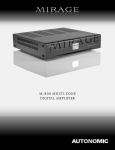
1
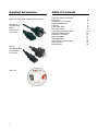
Axium AX-800DAV Multi-Zone Digital Amplifier Instruction Manual Important Safety Instructions 1 2 3 4 5 6 7 8 9 10 11 12 13 14 Read these instructions. Keep these instructions Heed all warnings Follow all instructions Do not use this apparatus near water Clean only with dry cloth Do not block any ventilation openings, Install in accordance with the manufacturer’s instructions Ensure that the ventilation is not impeded by covering the ventilation openings with items such as newspapers, table cloths, curtains, etc. Do not install near any heat source such as radiators, heat registers, stoves or other apparatus (including amplifiers) that produce heat. Use the apparatus only in moderate climates (not in tropical climates). Do not defeat the safety purpose of the polarized or grounding type plug. A polarized plug has two blades with one wider than the other. A grounding type plug has two blades and a third grounding prong. The wide blade or third prong are provided for your safety. If the provided plug does not fit into your outlet, consult an electrician for replacement of the obsolete outlet. Protect the power cord from being walked on or pinched particularly at plugs, convenience receptacles, and the point where they exit from the apparatus. Only use the attachments/accessories specified by the manufacturer. If you install the apparatus in a built-in installation, such as a bookcase or rack, ensure that there is adequate ventilation. Leave 20cm (8”) of free space at the top and sides and 10cm (4”) at the rear. The rear edge of the shelf or board above the apparatus shall be set 10cm (4”) away from the rear panel or wall, creating a flue-like gap for warm air to escape. Good airflow is necessary to help ensure proper operation. Not only should you provide enough free space around the unit, but also ensure that air can flow freely and escape from the amplifier surroundings. Failure to do so may cause thermal shutdown of the unit, and reduced life expectancy. 15 Unplug this apparatus during lightning storms or when unused for long periods of time. 16 Never expose the unit to moisture 17 Refer all servicing to qualified service personnel. Servicing is required when the apparatus has been damaged in any way, such as power-supply cord or plug is damaged, liquid has been spilled or objects have fallen into the apparatus. The apparatus has been exposed to rain or moisture, does not operate normally, or has been dropped. 18 Damage requiring service Unplug the apparatus from the wall outlet and refer servicing to qualified service personnel under the following conditions: A) When the power supply cord or plug is damaged B) If liquid has been spilled, or objects have fallen into the apparatus. C) If the apparatus has been exposed to rain or water, D) If the apparatus does not operate normally by following the operating instructions. Adjust only those controls that are covered by the operating instructions as an improper adjustment of other controls may result in damage and will often require extensive work by a qualified technician to restore the apparatus to its normal operation. E) If the apparatus has been dropped or damaged in any way, and F) When the apparatus exhibits a distinct change in performance this indicates a need for a service. 19 Object and Liquid Entry Never push objects of any kind into the apparatus through openings as they may touch dangerous voltage points or short-out parts that could result in a fire or electric shock. The apparatus shall not be exposed to dripping or splashing and no objects filled with liquids, such as vases, shall be placed on the apparatus. Don’t put candles or other burning objects on top of this apparatus. 2 Precautions 1. AC Fuse - The AC fuse inside the unit is not userserviceable. If you cannot turn on the unit, contact the dealer from whom you purchased this unit. 2. Care - Occasionally you should dust the unit all over with a soft cloth. For stubborn stains, use a soft cloth dampened with a weak solution of mild detergent and water. Dry the unit immediately afterwards with a clean cloth. Don’t use abrasive cloths, thinners, alcohol, or other chemical solvents, because they may damage the finish or remove the panel lettering. 3. 4. 3 Power WARNING BEFORE PLUGGING IN THE UNIT FOR THE FIRST TIME, READ THE FOLLOWING SECTION CAREFULLY. AC outlet voltages vary from country to country. Make sure that the voltage in your area meets the voltage requirements printed on the unit’s rear panel. (e.g. AC 90V – 240V 50/60HZ) The power cord is used to disconnect this unit from the AC power source. Make sure that the plug is readily operable (easily accessible) at all times. If you do not intend to use the unit for an extended period, remove the power cord from the AC outlet. Earth – The unit is defined as Class1 in EN60065 (low voltage directive) and MUST BE EARTHED. Connect only to a mains socket outlet with protective earth, and only use the power cord supplied. Finland: “Laite on Liitettävä suojamaadoituskoskettimilly varustettun pistorasiaan” Norway: “Apparatet må tilkoples jordet stikkontakt” Sweden: ˶Apparaten skall anslutas till jordat uttag” 5. Never Touch This Unit With Wet Hands – Never handle this unit or its power cord while your hands are wet or damp. If water or any other liquid gets inside this unit, have it checked by your Axium dealer. 6. Handling Notes • If you need to transport this unit, use the original packaging to pack it how it was when you brought it. • Do not leave rubber or plastic items on this unit for a long time, because they may leave marks on the case. • This unit’s top and rear panels may get warm after prolonged use. This is normal. • If you do not use this unit for a long time, it may not work properly the next time you turn it on, so be sure to use it occasionally. 7. Speaker Shorts Under no circumstances should the speaker output terminals of the unit be short circuited, grounded or connected to another output. 8. Direct Sun light - Avoid installing the amplifier in positions where the front panel is exposed to direct sunlight – may cause control to become sluggish. 9. Controller Connection - Never connect more than eight Axium controllers. The supply is internally fused (self resetting) and may open circuit. Never connect the unit’s 12VDC terminal (‘Bus Run’ port) to an external power supply. DECLARATION OF CONFORMITY We declare under our sole responsibility that this product, to which this declaration relates, is in conformity with the following standards: EN60065, EN55013, EN55020, EN61000-3-2 and EN61000-3-3. Following the provisions of Low Voltage Directive 2006/95/EC and EMC Directive 2004/108/EC, the EC regulation 1275/2008 and its frame work Directive 2009/125/EC for Energy-related Products (ErP). A NOTE ABOUT RECYCLING: This product’s packaging materials are recyclable and can be reused. Please dispose of any materials in accordance with the local recycling regulations. When discarding the unit, comply with local rules or regulations. Batteries should never be thrown away or incinerated but disposed of in accordance with the local regulations concerning battery disposal. This product and the supplied accessories constitute the applicable product according to the WEEE directive. For U.S. models FCC information for User CAUTION: The user changes or modifications not expressly approved by the party responsible for compliance could void the user’s authority to operate the equipment. Note: This equipment has been tested and found to comply with the limits for a Class B digital device, pursuant to Part 15 of the FCC Rules. These limits are designed to provide reasonable protection against harmful interference in a residential installation. This equipment generates, uses and can radiate radio frequency energy and, if not installed and used in accordance with the instructions, may cause harmful interference to radio communications. However, there is no guarantee that interference will not occur in a particular installation. If this equipment does cause harmful interference to radio or television reception, which can be determined by turning the equipment off and on, the user is encouraged to correct the interference by one or more of the following measures: • Reorient or relocate the receiving antenna. • Increase the separation between the equipment and receiver. • Connect the equipment into an outlet on a circuit different from that to which the receiver is connected. • Consult the dealer or an experienced radio/TV technician for help. For Canadian Models NOTE: THIS CLASS B DIGITAL APPARATUS COMPLIES WITH CANADIAN ICES-003 For models having a power cord with a polarized plug: CAUTION: TO PREVENT ELECTRIC SHOCK, MATCH WIDE BLADE OF PLUG TO WIDE SLOT FULLY INSERT. Modèle pour les Candadien REMARGUE: CET APPAPEIL NUMĖRIQUE DE LA CLASSE B EST CONFORME À LA NORME NMB-003 DU CANADA. Sur les modèles don’t la fiche est polarisée: ATTENTION: POUR ĖVITTER LES CHOCS ĖLECTRIQUES, INTRODUIRE LA LAME LA PLUS LARGE DE LA FICHE DANS LA BORNE CORRESPONDANTE DE LA PRISE ET POUSSER JUSQƯ AU FOND. 4 Supplied Accessories Table of Contents Make sure you have the following accessories: Important Safety Instructions Precautions Declaration of Conformity Supplied Accessories Features Front Panel Guide Rear Panel Guide Typical System Configuration Multiple Amplifier Stacks Controller Termination Menu Navigation WEB Application Axium Music Centre Program RS232 Protocol Specifications VDE CEE 7/7 European Plug Schuko to IEC60320 C13 socket AS3112 Australasian Plug to IEC60320 C13 Socket Axium CD 5 2 3 4 5 6 8 9 10 12 13 14 22 25 27 30 Features Thank you for purchasing an Axium AX-800DAV Multi-Zone Amplifier. Please read this manual thoroughly before making connections and plugging in the unit. Following the instructions in this manual will enable you to obtain optimum performance and listening enjoyment from your new Multi-Zone Amplifier. Please retain this manual for future reference. Multi-Zone, Multi-Source, Video Switching Ethernet, RS232, USB and IR control The 800DAV amplifier has six separate amplifiers and two separate preamplifiers, providing 8 zones of independent yet integrated control. There are 11 inputs sources comprising the following: Sources 1 – 6 are either Analog Stereo, or Coax Digital Audio (PCM). Sources 7 & 8 are either Coax or Optical Digital Audio (PCM) Source 9 is either spawned from the USB Host, or Ethernet S10 is the Door-Bell .wav playback source typically used for paging applications. The first 4 zones have a 4 source composite video switcher, so monitor screens in four different rooms may display any of the first 4 sources (S1 – S4). The 800DAV amplifier may be controlled and monitored via the rear Panel USB, RS232 serial interface or Ethernet. In multi amplifier installations where the amplifiers are interconnected using an expansion bus cable, only one Ethernet or RS232 connection is required to control the stack of amplifiers. An 800DAV amplifier may receive IR directly from the front panel receiver or via the eight ‘Controller’ connections. There are zone specific IR commands and also a set of global IR commands. The commands are: ON, OFF, Standby (toggling), Mute, Volume Up, Volume Down, Source Selects, Discrete Audio Source Selects, Discrete Video Source Selects, On with Source Specific commands. The Global commands also include PRESET1 – PRESET 14, Alarm Enable, Alarm OFF, & 5 minute Sleep. Preamplifiers and Outputs Each zone has bass, treble, balance and loudness control. These are accessed either from the front panel or AMC (Axium Music Centre) program. A feature called ‘Maximum Volume limiting’, is useful for protecting connected speakers. It may be applied to both amplifier and preamplifier outputs. Amplifier Power, Protection, and Clipping Indicators 50 Watts RMS per channel into 8 ohm loads. Capable of driving into 4 ohm loads. The amplifiers are protected against output shorts, and have algorithms that prevent hard clipping when the zone amplifiers are overdriven. Thermal Control There are two progressive levels of thermal control: • The amplifier volume is reduced 20dB. • The amplifiers are shutdown until the temperature reduces below the first level. Care should be taken to ensure adequate ventilation – see “Important safety instructions” on page 1 Real Time Clock The 800DAV amplifier is equipped with a real time clock. The amplifier may be set up to function as an alarm clock, so that at 6.30am in the morning 5 days a week, the master bedroom zone could be made to turn on, select tuner, and go to a specific volume. Multiple Alarms are feasible (max of 14) however the Alarm Enable & OFF commands act upon all programmed Alarms. The Clock automatically compensates for daylight saving. The clock continues to operate typically > 48 hours without power – more than enough to keep the time current during lengthy power outages. IR Emitter Ports There are 10 Buffered IR emitter Ports. Ports 1 – 8 have IR routing, and are intended to control specific input source components. Two IR ports 9 & 10 are the sum of all IR sources; these control the ‘All’ zone source components. 6 Presets and Paging Buffered Video Outputs There are 14 amplifier presets and two page presets. Presets 1 - 14 are momentary and cause the amplifier to go to a predetermined setup, i.e. standby, volume & source selection. The presets may also be programmed with event scheduling, and are used by the alarm clock. The ‘Page Preset’ mode is for paging applications and is invoked by a contact closure between the 0V and PG1 or PG2 terminals. The contact closure must have an external power source i.e. a 12 – 24V AC/DC powered door bell. When the contact closure is released (power sensed across PG – 0V terminals) the amplifier zones return to their previous states. PG1 is always assigned to the Page Preset. PG2 may be assigned to any one of the 15 available Presets. The composite video inputs are buffered for the purpose of expanding to other amplifiers in the installation. Zone Linking After an AC power outage the 800DAV amplifier restores its settings to the pre-interrupted state. All internal settings are stored in non-volatile memory, except the clock that runs for at least 48 hours on stored power. A zone may be programmed to link multiple zones. Zone linking ties the source selection together. It may also tie the volume, and standby. This is useful for closely coupled audio areas where it is advantageous to have different volume control but the same source, or the same volume with separate standby control. Zone linking is setup either via the front panel user interface or AMC program. 96 Zones There are 96 zones of possible control. On an 800DAV amplifier each zone must be different, however in a multiple amplifier stack same zone amplifiers are possible – they simply mimic every parameter. Expansion Bus Data, IR & Amp-On are interconnected via the expansion bus. One amplifier is connected to another using a standard RJ45 patch cable. Connections are made between amplifiers using either of the two RJ45 expansion bus sockets. Door Bell Up to 10 seconds of 44.1 KHz 16 Bit stereo sounds may be generated as part of a page preset. Suitable ‘wav’ files are uploaded to the unit using the AMC program. 7 Discrete Video and Audio Selection The Video and Audio selection may be independent. There are RS232 and IR Discrete control commands available. Amplifier ON Status – “Amp-On” Each zone has AMP-ON status: 12VDC OUT on the rear panel connector: (1, 2, 3, 4, 5, 6, 7, 8). The ‘AMP ON’ output’s are protected against shorts. Power Failure Restoration Restore Defaults The 800DAV amplifier may be readily set to the default settings. Restoring Defaults clears all memory and resets the zone allocations to zones 1 – 8. Setup Lockout Locks access to the System Setup and More menus where installation critical adjustments can be made. Password = 1396 Firmware Upgradable The 800DAV amplifier may be updated with the latest operational firmware, using the Axium AMC program. Front Panel Guide 1 2 3 4 5 6 1 Front Panel Solid Aluminium front Panel 2 Infra-Red Receiver Receiver for front panel IR control – Used only for amplifier control, not IR pass through. 3 Power Indicator The power indicator glows blue whenever AC power is applied. 4 USB Host The port is used for Memory stick Digital music playback. 6 5 2.4” Colour LCD Touch Panel display LCD Touch Panel display for menu guided control and programming. The display is dimmed to “Off” after 15 minutes of inactivity. 6 Chassis Feet Set high enough to provide unrestricted air-flow through the chassis for convection cooling. 8 Rear Panel Guide 1 2 3 4 11 5 12 13 6 14 15 7 8 9 16 17 10 18 1 AC Inlet IEC socket 11 Zone Preamplifier Out Analog Audio L/R Zone 7 and 8 outputs. 2 Speaker Terminals Plug in terminal clamp connectors accept 1.5mm² speaker wires 12 Analog Input Terminals Analog Audio L/R inputs 3 Expansion Bus RJ45 patch cable connects between expansion bus ports of amplifiers in a stack. 4 Coax Digital Input Terminals Coax digital (SPDIF) inputs. 5 Coax Digital Source Output Terminals Coax digital outputs for expansion to further amplifier zones. 6 Buffered Video Out The composite video inputs are buffered to enable expansion to further amplifiers. 7 CVBS Video Input Terminals Composite (CVBS) video inputs. 8 USB for programming USB mini B socket for programming and firmware updates. 9 Ethernet Port This port is used for control, monitoring and data access. 10 RS232 Communication Port The port is used for setup, control or monitoring. A straight through cable must be used when connecting to a PC or control system. 9 13 IR Emitter Ports 3.5mm mono jacks. IR1 and IR8 are used to control specific source equipment, where full IR routing is assigned by the connected controller. IR9 & IR10 are used to control source equipment common to all zones. These ports output the combined IR1 – IR8 infra-red strings. 14 Optical Digital Inputs Optical (TOSLINK) digital inputs 15 Switcher CVBS Output Terminals Composite video matrix switcher outputs for Zones 1 - 4 16 Controller Interface For connection to keypads and IR receivers. 8 controller interface ports - RJ45 sockets 17 Bus Run Controller Interface Legacy ‘BUS RUN’ port (4 way terminal block) 18 AMP ON Control 12 – 24V AC/DC powered doorbell - contact closure between PG1 or PG2 and Common (C) terminals Invokes a preset enabling paging or doorbell function. AMP-ON 1 - 8 output 12VDC when Zone is ON. Typical System Configuration Zone 1 Gym AX-KPD Zone 2 Study AX-KPC Active Subwoofer Zone 3 Lounge TABLET To Ethernet router DVD PLAYER Speakers in other Zones - not shown R SATELLITE RECEIVER TUNER CD PLAYER FIG 1 10 Typical System Configuration – Continued Fig 1 depicts a typical configuration where the 800DAV amplifier is providing audio into six of the possible eight listening zones. Only three of the Zones are depicted. Each zone consists of a room with a pair of speakers and a suitable controller. Additionally a zone may have monitors or TV screens. In Fig 1 two such screens are shown in the Gym and Lounge. Each zone may be listening / watching any of the connected sources: Satellite, DVD, Tuner, Internet Radio, Media server, CD etc. Controllers Source Equipment Each zone has a specific control requirement. Choose controllers that best suit the application. The 800DAV amplifier has six stereo RCA audio inputs for connecting to source equipment. These input channels also feature Coax Digital inputs. If a signal is present on the Digital input it takes precedence over the Analog input. There are two additional Digital only input channels featuring both coax and Optical inputs. A zone may select from any of the connected sources. Someone in the Lounge may be listening and viewing the DVD, while another in the Study may be listening to music from the media server. All eight zones may select the same source, in such circumstances there is a possibility that all eight zones may be trying to control that source – not always desirable – so a system should be well planned and where appropriate additional source equipment installed. • • • Zone 1 – The Gym: Keypad with IR receiver Zone 2 – The Study: Keypad Zone 3 – The Lounge: Tablet The Axium Keypad’s may be plugged into any of the eight Controller ports. Source control IR emitters are plugged into the IR Ports. There are ten IR ports: IR1 - IR8, and IR9 & IR10. IR 1 – RI8 route source specific IR signals from connected controllers, while IR9 & IR10 output the common IR or the sum of all received IR signals. These Ports may be used for source equipment that is common to all zones. When controlling the 800DAV using an iPad or other Web tablet, the 800DAV must be connected to a WIFI enabled Ethernet router and the Web Tablet browser must be directed to the 800DAV’s IP Address. The 800DAV’s WEB application also provides source control functionality. The 800DAV can store and regenerate source equipment IR commands. The 800DAV can be directed to output the IR commands to a specific IR output port as required. This advanced feature is programmed using the Axium Keypad manager program (AKM) Speakers Speakers in each zone are connected to the amplifier by “Home Run” speaker cables. Video Outputs The composite video outputs are suitable for driving ONE composite video display device. To avoid signal degradation, home runs of appropriate 75Ω video cable should be less than 100 meters. 11 Preamplifier Zone Outputs The preamplifier output zones are completely independent of the Digital amplifier zones. These can optionally be used for locations where a high or lower power amplifier / speaker would be required. A third party power amplifier is required to power the Zone speakers. Alternatively a preamplifier Zone may be Zone linked to one of the Digital amplifier zones, and provide line level outputs to the zones subwoofer. This is what is shown in the Study, where the preamplifier zone 7 provides the active subwoofers line level. In this case Zone 7 must be Zone Linked to Zone 2 and Zone linking options for Link Volume and Link Standby have been selected. Multiple Amplifier Stacks To Next AX-800DAV or AX-400DA Multi-Zone Amplifier DVD PLAYER SATELLITE RECEIVER TUNER CD PLAYER FIG 2 In large installations where multiple 800DAV amplifiers are required, the expansion bus may be used to convey inter-amplifier control, and common IR control. The source equipment audio and video inputs must be plugged into the first amplifier where they are buffered and sent to the next amplifier in the stack. The maximum recommended expansion is eight units. Fig 2 shows inter-connected amplifiers using an RJ45 expansion bus lead, and RCA leads for the source Digital coax signals. Amplifier Control using Ethernet, RS232 or USB may be connected to any one of the 800DAV’s in the stack. If the media server is to be used on each 800DAV then Ethernet should be routed to each 800DAV, this is because Ethernet access is not relayed through the Expansion bus. 12 Controller Wiring The 800DAV is packed with control options: • • • • • • • • USB: Intended for initial installation Programming or firmware update. Not intended for permanent connection to a PC or other control system. ETHERNET: 100BaseT connection to a Home network router or switch. RS232 Serial: Electrically isolated Prevents hum in analog input circuits. CONTROLLERS: Conveys +12VDC, IR and Data between the 800DAV and Axium keypad controllers, connected Using CAT5 cables. BUS RUN: (Legacy) Port conveys +12VDC, IR & Data to remotely connected IR controllers. AMPON: +12VDC 100mA trigger output when a Zone is ON. PRESETS: P1 and P2 Inputs are active low. Connect C (common) and either P1 or P2 across an illuminated door bell switch. The illuminated doorbell switch must have an External 12V – 24V AC/DC supply and current limiting resistor connected. If a dry contact is to be used for PRESET Activation, it must be normally closed or a Push to break contact. The BUS RUN 0V and +12V can be connected as shown in FIG 3 FIG 3 EXPANSION BUS: Simple Patch cable interconnection for Axium amplifiers that conveys control and data between Amplifiers in a stack. The cable length must be < 0.5m. Interconnection to older Axium amplifier models is possible only for the Control functions. A special cable must be made. See FIG 4 In older Axium amplifier models Analog audio was conveyed through a 34 way IDC cable. This is no longer supported, and connections must be done using RCA splitters in the analog audio inputs. FIG 4 13 Menu Navigation Front Panel User Interface: The Axium 800DAV amplifier has a 2.4” Touch Panel LCD colour display which is used for control and accessing status of all amplifier functions. After 2 minutes of inactivity the LCD dims to 50% brightness, after a further 15 minutes it dims OFF. A Touch on the screen will restore the LCD to full brightness, enabling touch control. Home Page The home page provides access to the Amplifier zones: Zone1 - Zone 8. Selecting a Zone opens its control page. Zone Control Page The eight Zones each have different background images, but same function. At the top of the control page the Zone and current time & day are displayed. The ‘Zones’ button is the Home Page return. The Control page provides status & control for the selected Zones: • Standby • Volume Slider • Volume Up / Down with Digit readout • Source Selects S1 – S4 • Mute If the button is blue it indicates selection or ON status. The Volume slider changes colour as the volume increases, i.e. Green –Yellow – Red. 14 Selecting the ‘More’ button will display the next sources: S5 – S8. To change the selected source, simply push the required source button. If the ‘More’ button is selected again the conditional sources will be displayed if these are connected, otherwise the Source selection loops back to the Start: S1 – S4. Conditional Sources are: USB – Memory Stick inserted in Front Panel Media Player – Ethernet connection to server I-Radio – Accessible Internet. More Functions Page When the “More” button is pressed and held for >1second a More functions Page opens. There are four Zone specific functions that when selected navigate to setup pages: • EQ • Levels • Zones • Delay There is also a System function which is not zone specific. The System page is covered later. Note System functions may be accessed via any of the Zones ‘More functions’ pages. The Back arrow button returns to the Zone Control Page. 15 EQ Setup Page The EQ setup page provides status & control for the selected Zones: • Bass ± 12dB using Slider or Up/Down button • Treble ±12dB using slider or Up/Down Button • Loudness Control – toggle. The Back arrow button returns to the More Functions Page. Levels Setup Page The Levels setup page provides status & control for the selected zones: • Balance ±20dB using slider or Left/Right button • Maximum Volume Limiting – can be reduced over the range from 100 to the minimum of 2 using the slider or Up/Down button The Back arrow button returns to the More Functions Page. Delay Setup Page The Delay setup page provides a single slider and Up/Down control for adjusting the Zones Audio Delay time. It may be adjusted over the range from 0 – 120ms The Back arrow button returns to the More Functions Page. 16 Zones Setup Page Zones setup page provides the means to name and set the Zone coding. There is also a Button for Zone linking setup. To change the Zone allocation simply make the adjustment using the Up/Down button. The Back arrow button returns to the More Functions Page. To Name the Zone select ‘Edit’ The Zone Name Page opens: Zone Name Page Use the keypad to enter the Name text, The limit is 15 regular ASCII characters. Once entered, select the back arrow to return to the Zones Setup Page. Zone Linking Page The Zone may be linked with any other zone or zones. Make the selection by scrolling through the zone list and choosing OK. The Type of Zone Linking: Link Volume or Link Standby may be selected. When Link volume is selected the linked zone(s) will track the source and volume settings. When Link Standby is selected the Linked Zone(s) will behave as if they are the same zone. Once entered, select the back arrow to return to the Zones Setup Page. 17 System Page The System settings page opens when the System button is selected in any of the ‘More function pages’ for longer than 5 seconds. The System settings are Zone independent functions. The page displays the internal amplifier heatsink temperature. Select the Close button to return to the Zone Page. Set Clock Page The clocks time and time zone is automatically synchronised when connected to the internet or to a PC using the USB connection. However the clock settings and how the clock is displayed may be adjusted. Select the Back arrow to return to the System settings Page. Restore Defaults Page To restore the 800DAV to factory defaults select ‘Yes’, or to return to previous menu select ‘No’. Factory defaults resets the zone allocations back to 1 - 8 Clears all settings like Zone and Source Names, Presets, Zone linking, Maximum volume limits, Bass, Treble and Loudness etc. 18 Setup lockout Page You may lock the user out from making critical installation setting changes, by enabling the Setup lockout. After which the user can not access the System Settings menus. Select ‘Yes’ to enable this option, or ‘No’ to return to the previous menu. Sources settings Page Select the Source to be adjusted From S1 – S8 This opens the Source Edit page. Or select the Back arrow to return to the System settings Page. A Source may be named, by using the phone Keypad. The analog input gain can be adjusted using the Gain slider or Up / Down buttons. Gain is used to match the analog input levels to the Digital sources. Some Analog sources have large variation in output levels. The 0dB default setting is suitable for connection to high output devices like DVD players, while the standard level (1Vrms) is achieved by setting the gain to +6dB. The Gain slider - and source button - will flash red if the gain is set to high and distortion is detected. Select the Back arrow to return to the System settings Page. 19 Network settings Page Network setting always defaults to DHCP. The connected Ethernet router’s allocated IP address can be viewed. If for some reason a Static IP is required the selection can be made, and settings adjusted using the back and forward arrow and plus minus keys. Select the Back arrow to return to the System settings Page. Presets Page There are 14 possible presets. It is easier to set up the presets using a connected PC running the Axium music centre program. However Presets can be setup using the 800DAV front panel GUI. The first 8 presets are accessible on the opening page. To access the remaining presets select the ‘More’ button Select the Back arrow to return to the System settings Page. Presets 9 – 14 and the Page Preset may be accessed. Selecting ‘More’ returns to the previous page displaying Presets 1 – 8. ‘Clear Alarms’ turns off all alarm settings. These can only be re-enabled by resetting the alarms in the preset. Select the Back arrow to return to the System settings Page. 20 This page is displayed after selecting a Preset. The Preset may be assigned the Page Preset 2 function. This is where the Preset is invoked when a PG2 contact closure is made on the rear panel. Once enabled it cannot be disabled unless re-assigned to a different Preset, or by Restore default. Select ‘Set up’ to enable the Preset Setup Mode. An Axium splash page is displayed followed by the Home Page. When in the Preset Setup mode Navigate through all the zones and make appropriate changes to the standby, volume and source selections etc. Once all settings have been adjusted, navigate back to the Preset: More/System setup/Preset, Select Yes to complete and exit the Setup Preset Mode, or No if you want to continue further settings changes. The ‘Set alarm’ button above navigates to the Alarm Preset page. The Alarm time and days that it is to be activated may be selected. The Alarm is set only if the Enable is set. Select the Back arrow to return to the System settings Page. The ‘Zone selection’ button above navigates to the Zones allocation page. Presets are system wide functions. Other 800DAV or 400DA amplifiers may be interconnected via the expansion bus. These amplifier zones can be included using the ‘Include All’ or excluded using the ‘Exclude All’ buttons. Alternatively each zone can be navigated through using the plus and minus buttons, and if to be included the OK button is selected. Select the Back arrow to return to the System settings Page. 21 WEB Application The Axium 800DAV amplifier has a WEB application which may be used for control and monitoring of amplifier and source functions. Home Page The home page provides access to the Amplifier Zones. Selecting a Zone opens its control page. The Zones shown above have been named. If un-named they are listed as Zone 1, Zone 2 etc. 22 Zone Control Page The Zone Control Page provides status & control of: • Standby • Volume: Slider or Up/Down button with readout. • Source Selection: S1 – S8, & Media or Front Panel USB stick if detected. • Mute If the button is blue it indicates selection or ON status. Because of Web browser limitations, Slider setting changes are made using a positional touch on the slider The ‘Zones’ button is the Home Page return. Selecting the ‘Settings’ button will open the Settings page. Source control may be provided - is setup using the Axium Keypad Manager program. 23 Zone Settings Page The Zone Settings Page provides status & control of: • Bass: Slider or Up/Down button • Treble: Slider or Up/Down button • Loudness • Balance: Slider or Left / Right button • Delay: Slider or Up/Down button • Maximum Volume Limit: Slider or Up/Down button There is information displayed about the connected amplifiers Model and Unit ID and firmware version. The amplifier heatsink temperature is also displayed. The Back arrow button returns to the Zone Control Page. 24 Axium Music Centre Program AMC is an amplifier setup program, full control and tracking of the Axium amplifier zone is provided. The program runs on PC’s running Win XP, Win 7 or VISTA operating systems, and communicates via RS232, USB or Ethernet. AMC’s main window provides user functionality for real-time access and control of any amplifier zone. When an Axium amplifier is first attached to a PC running AMC the amplifiers clock is automatically set to the PC’s current time, date and location. The Zone and Source buttons may be named by using a right mouse click over the button. A naming window opens where the name is entered. The name is saved in the connected 800DAV. File menu contains the commands: • New window: Opens another AMC main window. This is useful for displaying and controlling multiple zones simultaneously • Keypad window: A keypad window is displayed • • • • where a user can cause the selected keypad on the network to emit its stored IR strings. Download and save configuration: A configuration file contains all information in an installation stack, i.e. Zone allocation, Zone & Source naming, bass, treble, loudness, max volume limits, preset programming etc. Upload a saved configuration: Upload Audio file: Direct AMC to the file location of suitable “wav” files. Click Open & upload the file(s) to the amplifier. Exit: Shuts down AMC. Tools menu contains the commands: • Zone Assignment: Opens a window where the 800DAV Zones can assigned to between 0 – 95. Zones on one unit must be different. • IR Routing Tables: Opens a window with a selection table where the IR output ports can be mapped to specific Controller ports. 25 • • • • • Network Settings: Opens a window where a Network name can edited, and the IP address can be set to either DHCP or static input. A selection is provided for synchronizing with an internet time server. Media Servers: Opens a window where servers can be added and UNC path, Name & password entered. Party Mode Setup: Opens a window where a Master Unit can be assigned, and source allocated for Party Mode application. On the master unit the S8 SPDIF buffered output will play the allocated source, and all other connected amplifiers in a stack will select S8. Event Viewer: Open a window which displays a log of significant events in the amplifiers history. Advanced: Provides selections for Firmware update and a Real time log. Options Menu contains the port assignments, where the program lists the detected ports. Select USB, Ethernet or a suitable COM port for RS232. Note: Firmware update can only be performed using the USB connection. The Setup button opens the Setup window. Provides adjustments for Zone Equalisation, Balance, Delay, and Zone linking assignment. The Analog source input levels can be adjusted. If the source is a DVD player, the level should be set to 0dB. A Source will pulse red if input clipping is detected. Nominally the input should be set to 6dB. The Preset Setup on the AMC main page opens the Preset window. Preset programming can be entered for the Presets. Paging or Door Bell sound playback and triggers can be allocated. Do Not Disturb (DND), and Alarms or timed events may be allocated. Macros may be programmed where timer, Source & amplifier control may be involved in the Preset. 26 RS232 Protocol The RS232 serial port provides data acquisition and control of the Axium amplifiers by a home automation system, or PC. The interconnecting cable must be ‘Null modem’: 9 pin female ‘D’ connectors at both ends (pin connections 2 and 3 swapped at one end) only RX, TX & 0V (pin 5) are used. Baud Rate = 9600, Characters are all ASCII. Command Structure: <command><zone><data>line feed. Command Command 01 02 03 04 05 06 07 09 0B 0C 0D 0F 11 12 14 1C 1D 1E 26 28 Description Standby Mute Source Selection Volume Bass Treble Balance Send All parameters Cause key press on Keypad Amplifier features Maximum Volume Limit Link Zone Volume Up Volume Down Request Device information Zone Name Preamplifier Volume Mode Preset Selection / status Volume BCD format Video Source selection Zone Amplifiers are encoded with up to 32 zones The zone byte is used for checking if the command is applicable to the device receiving the command and if so, for optionally selecting a “sub-device”, e.g. a bank or part of a device. All Zones are addressed using FF. - The lower 5 bits of the zone byte represent the zone 0 – 31 selection, i.e: 00000 bin = 00 (hex) = zone 0 00001 bin = 01 (hex) = zone 1 01010 bin = 0A (hex) = zone 10 11111 bin = 1F (hex) = zone 31 - The upper 3 bits represent the standard amplifier = page preset amplifier = standard preamplifier = page preset preamplifier= Examples: 27 sub-device. The sub-device codes for an Axium amplifier are: 000 001 010 011 Addressing a zone 10 preamplifier: Binary 010-01010 or 2A hex Addressing a zone 10 amplifier: Binary 000-01010 or 0A hex Addressing all Zone amp & preamplifier: FF hex Send ASCII “2A” Send ASCII “0A” Send ASCII “FF” Data Command Standby (01) Mute (02) Source Selection (03) Volume (04) Bass (05) Treble (06) Balance (07) Send all parameters (09) Amplifier features (0C) Maximum Volume Limit (0D) Link Zone (0F) Volume Up (11) Volume Down (12) Zone Name (1C) Preamplifier Volume Mode (1D) Content 00 – Standby OFF 01 – Standby ON 04 – Toggle 00 – Mute 01 – Un-mute 02 – Toggle Mute 00 – S5 01 – S6 02 – S7 03 – S4 04 – S8 05 – S1 06 – S2 07 – S3 08 09 10 11 12 13 14 40 – S5 Audio only 41 – S6 Audio only 42 – S7 Audio only 43 – S4 Audio only 44 – S8 Audio only 45 – S1 Audio only 46 – S2 Audio only 47 – S3 Audio only 00 – A0 range F4 – 0C (-12db - +12db) F4 – 0C (-12db - +12db) EC – 14 (Left –20db – Right –20db) XX – value ignored 00 – Loudness enabled 01 – Loudness disabled 00 – A0 range 00 – 31 zone to be linked FF – for no zone linking XX – value ignored XX – value ignored Data field contains the ASCII string 00 – A0 range FF = Independent mode. 28 Command Preset Selection (1E) Volume BCD Format (26) Video Source selection (28) Content All Zone function: Zone byte = FF 00 – Default : exit preset mode 01 – Force “Page Preset” 02 – Select Preset 1 03 – Select Preset 2 04 – Select Preset 3 05 – Select Preset 4 06 – Select Preset 5 07 – Select Preset 6 0 – 99 in BCD format same as Front Panel display 00 01 02 03 04 05 06 07 – – – – – – – – S5 S6 S7 S4 S8 S1 S2 S3 Video Video Video Video Video Video Video Video Notes: Commands are used as notifications. If an amplifier is switched ON, it will notify the other devices on the Control Bus by sending the Standby command (01). Any amplifiers with the same zone will take the notification as a command and also switch ON. When a command is sent to an amplifier it will first be transmitted on the control bus and then returned to the PC (Home automation system). If an error occurs an error will be returned instead of the original command. The PC (Home automation system) needs to ignore its command when it is returned A Standby ON command implies that the amplifier is not muted, if the amplifier was previously Off, a mute command must follow the Standby command if it is muted. Not all Command and Data commands are covered in this document. The expected reply for the “Send all Parameters” command (09) is >144 bytes. All command fields listed in this document are contained in the reply. The reply also contains advanced commands not listed in this document. The home automation or PC’s buffer should be large enough to receive and process the 144-byte reply. If two pairs of zones are linked on an Axium amplifier, i.e. zones 1 & 2 and zones 3 & 4, and a “Link Zone” command is sent that links zones 2 & 3, then the amplifier has the following implications: Zone 2 links to Zone 3 Since zone 2 is no longer linked to zone 1, zone 1 shall no longer be linked to zone 2. Since Zone 3 is no longer linked to zone 4, zone 4 shall no longer be linked to zone 3. Example strings: 010A01: 012A01: 060002: 03IF02: 29 Standby ON command for zone 10 amplifier Standby ON command for zone 10 preamplifier +2db Treble setting on zone 0 Tuner source selection on zone 31 Specifications Amplifier Section Rated Output Power (FTC) All Channels: THD (Total Harmonic Distortion) Speaker Impedance (Z1 – Z6 L/R) Input Sensitivity and Impedance (S1 – S6 L/R) Coax digital input level and Impedance Preamplifier Output Level and Impedance ( Z7 & Z8 L/R) Frequency Response Tone Control Signal to Noise Ratio 50 Watts / channel, 8Ω loads, 0.1% (40 Watt, 8Ω load) 4Ω - 8Ω 0.72 V / 22KΩ (Unbalanced) 0.5V ± 0.05V / 75Ω +16dB / 470Ω 20Hz – 20 KHz / – 3dB (8Ω) ±12dB, 100 Hz (Bass) ±12dB, 10 KHz (Treble) 100dB (IHA-A, 1V input / unbalanced) Video Section Input Level & Impedance (S1 – S8) Buffered Video Output Level & Impedance (S1 – S8) Output Level & Impedance (Z1-Z4) 1 Vp-p / 75Ω (Composite) 1 Vp-p / 75Ω (Composite) 1 Vp-p / 75Ω (Composite) Interface IR Output Expansion Bus Ethernet RS232 USB Controller Amp On & PG Control Ten 3.5mm Jack: IR1 – IR10 current limited to 25mA. One Dual RJ45 Socket: Axium Bus, Summed IR One Shielded RJ45 socket – 100Base T One Isolated DB9 – 9600 Baud One USB mini-B 5 pin One: 4 way terminal blocks (0V, IR, 12V & Data). One: 10 way terminal plug with Amp ON 1 – 8 and Two Page preset contact closure inputs: PG1 & PG2. General Power Supply Power Consumption Standby Power Consumption Dimensions Height including feet Weight 110 – 240VAC 50/60 HZ 320 W 6W 435 х 90 х 390 mm 105mm 7Kg Specifications and features are subject to change without notice. 30