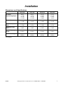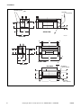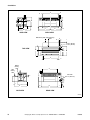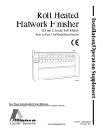
1
Installation/Operation
Chest Heated
Finishers
24 inch (600 mm) Models and 32 inch (800 mm) Models
Refer to Page 2 for Model Identification
Keep These Instructions for Future Reference.
(If this machine changes ownership, this manual must accompany machine.)
www.comlaundry.com
Part No. 1800000R2
September 2007
Table of
Contents
Introduction.........................................................................................
Model Identification .............................................................................
Serial Plate Location.............................................................................
Replacement Parts ................................................................................
Customer Service..................................................................................
2
2
3
3
3
Safety....................................................................................................
Explanation of Safety Messages...........................................................
Important Safety Instructions ...............................................................
4
4
5
Installation...........................................................................................
Dimensions and Specifications.............................................................
Pre-Installation Inspection ....................................................................
Location Requirements.........................................................................
Moving Finisher with Crane.................................................................
Moving Finisher with Forklift ..............................................................
Electrical Connection............................................................................
Gas Connection.....................................................................................
Inlet Pressure....................................................................................
Manifold Pressure ............................................................................
Steam Connection.................................................................................
Steam Connection Requirements.....................................................
Exhaust Requirements ..........................................................................
Start-up Procedures...............................................................................
Purging Moisture .............................................................................
7
7
12
12
13
13
14
17
18
18
19
19
20
21
21
Operation Instructions .......................................................................
Pre-Operation........................................................................................
Daily Check Points ..........................................................................
Operating Instructions ..........................................................................
Temperature Setting..............................................................................
22
22
22
23
23
Maintenance ........................................................................................
General Maintenance ............................................................................
Cleaning the Beds .................................................................................
Cleaning Beds ..................................................................................
Padding Specification ......................................................................
Reclothing The Roll .........................................................................
Baking of Roll Padding....................................................................
Hydraulic Pressure Settings..................................................................
Scrapers.................................................................................................
Extended Periods of Non-Use ..............................................................
24
24
25
25
25
25
26
27
28
28
Troubleshooting .................................................................................. 29
Troubleshooting Guide ......................................................................... 29
Troubleshooting Undesirable Finishes ................................................. 30
© Copyright 2007, Alliance Laundry Systems LLC
All rights reserved. No part of the contents of this book may be reproduced or transmitted in any form or by any
means without the expressed written consent of the publisher.
1800000
© Copyright, Alliance Laundry Systems LLC – DO NOT COPY or TRANSMIT
1
Introduction
Model Identification
Information in this manual is applicable to these
models:
UL24F118
UL24F130
UL24R118
UL24R130
UL24A118
UL24A130
UL32F118
UL32F130
UL32R118
UL32R130
UL32A118
UL32A130
2
© Copyright, Alliance Laundry Systems LLC – DO NOT COPY or TRANSMIT
1800000
Introduction
Serial Plate Location
Replacement Parts
Always provide the machine’s serial number and
model number when ordering parts or when seeking
technical assistance. Refer to Figure 1 for serial plate
location.
If literature or replacement parts are required, contact
the source from whom the machine was purchased or
contact Alliance Laundry Systems at (920) 748-3950
for the name and address of the nearest authorized
parts distributor.
Customer Service
For technical assistance, call the following number:
(920) 748-3121
Ripon, Wisconsin
cc
1
FWF57N
1
Serial Plate
Figure 1
1800000
© Copyright, Alliance Laundry Systems LLC – DO NOT COPY or TRANSMIT
3
Safety
Explanation of Safety Messages
Safe operating and maintenance practices presented in
this manual are emphasized with special safety
messages. These messages are categorized as
DANGER, WARNING and CAUTION. Explanations
of these categories are listed below.
Safety signs and labels are also placed on the unit.
Those signs and labels are limited messages. These
signs are to be inspected for readability and replaced
when missing, damaged, or unreadable. Refer to the
Maintenance section of this manual for the periodic
maintenance schedule. Refer to the parts manual for
ordering information.
These safety messages are used throughout this
manual to identify safe practices. Signal words are
placed with descriptions or steps where the need to
maintain safe conditions is critical.
IMPORTANT: The word "IMPORTANT" is used
to inform the reader of specific procedures where
minor machine damage will occur if the procedure
is not followed.
DANGER
Indicates an imminently hazardous
situation that, if not avoided, will cause
severe personal injury or death.
WARNING
Indicates a hazardous situation that, if not
avoided, could cause severe personal
injury or death.
NOTE: The word "NOTE" is used to communicate
installation, operation, maintenance or servicing
information that is important but not hazard
related.
The WARNING and IMPORTANT instructions
appearing in this manual are not meant to cover all
possible conditions and situations that may occur. It
must be understood that common sense, caution and
carefulness are factors which CANNOT be built into
this finisher. These facts MUST BE supplied by the
person(s) installing, maintaining or operating the
finisher.
Always contact your dealer, distributor, service agent
or the manufacturer on any problems or conditions you
do not understand.
CAUTION
Indicates a hazardous situation that, if not
avoided, may cause minor or moderate
personal injury or property damage.
4
© Copyright, Alliance Laundry Systems LLC – DO NOT COPY or TRANSMIT
1800000
Safety
Important Safety Instructions
(Save These Instructions)
WARNING
To reduce the risk of fire, electric shock,
serious injury or death to persons when
using your press, follow these basic
precautions:
W372
1. Read all instructions before using the finisher.
2. Do not finish articles that have been previously
cleaned in, washed in, soaked in, or spotted with
gasoline, dry cleaning solvents, or other
flammable or explosive substances, as they give
off vapors that could ignite or explode.
7. Protect yourself and fellow workers by making
sure that everyone follows all the rules. Read and
follow all safety labels and warnings. Learn all
aspects of the equipment such as what is hot,
which parts move, all safety shut-offs, and all
emergency procedures. Do not come close to
moving or heated parts. Do not wear loose
clothing, sweaters, jewelry, or neck ties when
near the finisher.
8. Frequent scheduled safety meetings are a must to
review and update rules. If anyone is observed
breaking the rules, the supervisor or manager
should be notified immediately. Reporting people
for rule breaking could save their lives or limbs.
9. Emergency shut-offs such as finger bars and
emergency stop switches, should be painted red
and clearly labeled.
3. Do not allow children to play on or around the
finisher. Close supervision of children is
necessary when the finisher is used near children.
This is a safety rule for all appliances.
10. Maintenance personnel should work in a buddy
system for mutual protection when working on a
finisher.
4. Check the operation of the safety finger guard at
the beginning of every shift. Operating the safety
guard should stop the finisher immediately. If this
safety feature is not working properly, employees
must shut off the finisher and notify the
supervisor. Do not operate the finisher until the
safety finger guard is repaired and working
properly. Be sure that all other safety features,
including guards and panels, are in place before
operating the finisher.
12. Do not install or store the finisher where it will be
exposed to water and/or weather.
5. Never service the finisher while it is running.
Never reach over, under, or behind the safety
finger guard or into any area near hot surfaces or
moving parts without first shutting off the
finisher at the switch and power source. Follow
this rule whenever working on the finisher to
avoid serious injury from the finisher’s heat and/
or pressure.
6. Never try to remove, adjust, or straighten jammed
or misfed linen while the finisher is running.
Attempting to clear the jammed linen item can
result in the user being caught in the linen and
pulled into the finisher. If something is jammed
in the finisher, turn off the power before
attempting to correct the problem. Avoid contact
with heated parts.
1800000
11. If in doubt, don’t. Do not do anything until the
supervisor or service-maintenance department
has been contacted. Only qualified personnel
should service the finisher.
13. Do not tamper with the controls.
14. Do not repair or replace any part of the finisher or
attempt any servicing unless specifically
recommended in this installation/operation
manual.
15. To reduce the risk of fire, DO NOT FINISH
plastics or articles containing foam rubber or
similarly textured rubber-like materials.
16. Keep area around the exhaust opening and
adjacent surrounding area free from the
accumulation of lint, dust, and dirt.
17. The interior of the finisher and the exhaust duct
should be cleaned periodically by qualified
service personnel.
18. If not installed, operated, and maintained in
accordance with the manufacturer’s instructions,
or if there is damage to or mishandling of this
product’s components, use of this product could
expose you to substances in the fuel or from fuel
combustion which can cause death or serious
illness and which are known to the State of
California to cause cancer, birth defects, or other
reproductive harm.
© Copyright, Alliance Laundry Systems LLC – DO NOT COPY or TRANSMIT
5
Safety
19. To reduce the risk of fire, DO NOT FINISH
articles which have traces of any flammable
substances such as machine oil, vegetable oil,
cooking oil, flammable chemicals, thinner, etc. or
anything containing wax or chemicals such as in
mops and cleaning cloths, or anything drycleaned at home with dry-cleaning solvent.
WARNING
To prevent serious injury or death, read
finisher manuals before installing,
operating, maintaining, or cleaning the
finisher.
W676
20. ALWAYS disconnect the electrical power to the
finisher before servicing. Disconnect power by
shutting off appropriate breaker or fuse.
21. Install this finisher according to the Installation
instructions in this manual. All connections for
electrical power, grounding, and gas supply must
comply with local codes and be made by licensed
personnel when required.
WARNING
To AVOID possible serious injury,
BEFORE maintenance or repair tasks:
• Disconnect all utilities such as gas,
electricity and steam.
• Allow heated parts and surfaces to cool.
W677
22. Do not turn hard or meltable materials into the
machine.
23. Do not operate the machine without feed sheets.
24. Do not crawl or walk on the machine.
25. Always wear protective gloves when working at
the machine. The beds are hot and hot linen exits
the machine.
6
© Copyright, Alliance Laundry Systems LLC – DO NOT COPY or TRANSMIT
1800000
Installation
Dimensions and Specifications
UL24*118
UL24*130
UL32*118
UL32*130
Roll Motor
*Optional High Speed
2.01 hp
(1.5 kW)
*2.95 hp
*(2.2 kW)
2.01 hp
(1.5 kW)
*2.95 hp
*(2.2 kW)
2.95 hp
(2.2 kW)
*5.36 hp
*(4 kW)
2.95 hp
(2.2 kW)
*5.36 hp
*(4 kW)
Exhaust Motor
1.01 hp
(.75 kW)
1.01 hp
(.75 kW)
1.01 hp
(.75 kW)
1.01 hp
(.75 kW)
Hydraulic Pump
Motor
.5 hp
(.37 kW)
.5 hp
(.37 kW)
.5 hp
(.37 kW)
.5 hp
(.37 kW)
Circulation Pump
Motor
4.02 hp
(3 kW)
4.02 hp
(3 kW)
4.02 hp
(3 kW)
4.02 hp
(3 kW)
Approx. Shipping
Weight
6503 lb.
(2950 kg)
7165 lb.
(3250 kg)
7605 lb.
(3450 kg)
8267 lb.
(3750 kg)
Approx. Net Weight
5732 lb.
(2600 kg)
6393 lb.
(2900 kg)
6834 lb.
(3100 kg)
7495 lb.
(3400 kg)
UL24 Models
1800000
© Copyright, Alliance Laundry Systems LLC – DO NOT COPY or TRANSMIT
7
Installation
With Delivery Table
Without Delivery Table
Gas Intake
1 in. (25.4 mm)
E
14o
H
A
F
B
C
G
REAR VIEW
D
FWF54N
SIDE VIEW
X
N
N
M
H
I
A
L
J
O
C
B
Y
P
Q
Z
FRONT VIEW
D
R
SIDE VIEW
TOP VIEW
Roll Exhaust
4.75 in. (120 mm)
S
W
T
J
U
V
X
8
© Copyright, Alliance Laundry Systems LLC – DO NOT COPY or TRANSMIT
Gas Outlet
4.75 in. (120 mm)
1800000
Installation
Dimension
UL24*118
UL24*130
A
35.43 in. (900 mm)
35.43 in. (900 mm)
B
23.62 in. (600 mm)
23.62 in. (600 mm)
C
55.11 in. (1400 mm)
55.11 in. (1400 mm)
D
78.74 in. (2000 mm)
78.74 in. (2000 mm)
E
4.13 in. (105 mm)
4.13 in. (105 mm)
F
12.40 in. (315 mm)
12.40 in. (315 mm)
G
14.37 in. (365 mm)
14.37 in. (365 mm)
H
40.55 in. (1030 mm)
40.55 in. (1030 mm)
I
39.17 in. (1030 mm)
39.17 in. (1030 mm)
J
36.22 in. (920 mm)
36.22 in. (920 mm)
K
18.90 in. (480 mm)
18.90 in. (480 mm)
L
40.94 in. (1040 mm)
40.94 in. (1040 mm)
M
57.09 in. (1450 mm)
57.09 in. (1450 mm)
N
4.33 in. (110 mm)
4.33 in. (110 mm)
O
19.68 in. (500 mm)
19.68 in. (500 mm)
P
14.57 in. (370 mm)
14.57 in. (370 mm)
Q
1.77 in. (45 mm)
1.77 in. (45 mm)
R
4.72 in. (120 mm)
4.72 in. (120 mm)
S
13.78 in. (350 mm)
13.78 in. (350 mm)
T
41.39 in. (1050 mm)
41.39 in. (1050 mm)
U
19.88 in. (505 mm)
19.88 in. (505 mm)
V
9.65 in. (245 mm)
9.65 in. (245 mm)
W
18.90 in. (480 mm)
18.90 in. (480 mm)
X
118 in. (3000 mm)
129.92 in. (3300 mm)
Y
126.77 in. (3220 mm)
138.58 in. (3520 mm)
Z
162.79 in. (4135 mm)
174.60 in. (4435 mm)
Table 1
UL32 Model
1800000
© Copyright, Alliance Laundry Systems LLC – DO NOT COPY or TRANSMIT
9
Installation
H
A
H
G
G
L
I
K
J
I
M
F
B
D
C
N
25
E
SIDE VIEW
REAR VIEW
With Delivery Table Without Delivery
Table
Q
I
R
Exhaust Outlet
Gas Outlet
6.25 in. (160 mm)
4.75 in. (120 mm)
K
TOP VIEW
M
P X
J
M
A
V
Without
Delivery
Table
V
A
With
Delivery
Table
F
U
Gas Intake
1 in. (25.4 mm)
O
T S
I
M
N
SIDE VIEW
F
B
E
I
REAR VIEW
FWF97N
FWF97N
10
© Copyright, Alliance Laundry Systems LLC – DO NOT COPY or TRANSMIT
1800000
Installation
Dimension
UL32*118
UL32*130
A
118 in. (3000 mm)
129.92 in. (3300 mm)
B
126.77 in. (3220 mm)
138.58 in. (3520 mm)
C
87 in. (2210 mm)
93.15 in. (2366 mm)
D
79.53 in. (2020 mm)
85.43 in. (2170 mm)
E
167.52 in. (4255 mm)
179.33 in. (4555 mm)
F
16.14 in. (410 mm)
12.40 in. (315 mm)
G
59.84 in. (1520 mm)
14.37 in. (365 mm)
H
4.33 in. (110 mm)
40.55 in. (1030 mm)
I
23.62 in. (600 mm)
39.17 in. (1030 mm)
J
40.16 in. (1020 mm)
36.22 in. (920 mm)
K
22.83 in. (580 mm)
18.90 in. (480 mm)
L
38.39 in. (975 mm)
40.94 in. (1040 mm)
M
63 in. (1600 mm)
57.09 in. (1450 mm)
N
86.62 in. (2200 mm)
4.33 in. (110 mm)
O
37.80 in. (960 mm)
19.68 in. (500 mm)
P
45.28 in. (1150 mm)
14.57 in. (370 mm)
Q
11.42 in. (290 mm)
1.77 in. (45 mm)
R
4.73 in. (120 mm)
4.72 in. (120 mm)
S
14.37 in. (265 mm)
13.78 in. (350 mm)
T
12.40 in. (315 mm)
41.39 in. (1050 mm)
U
4.92 in. (125 mm)
19.88 in. (505 mm)
V
.90 in. (23 mm)
9.65 in. (245 mm)
W
.98 in. (25 mm)
18.90 in. (480 mm)
X
48.03 in. (1220 mm)
129.92 in. (3300 mm)
Table 2
1800000
© Copyright, Alliance Laundry Systems LLC – DO NOT COPY or TRANSMIT
11
Installation
Pre-Installation Inspection
Location Requirements
Upon delivery, visually inspect the packaging and
portions of the finisher that are visible through the
packaging for shipping damage.
It is strongly recommended that the purchaser be
present during installation and the first tests.
If the package or finisher is damaged or if signs of
possible damage are evident, have the carrier note the
condition on the shipping papers before the shipping
receipt is signed, or advise the carrier of the condition
as soon as it is discovered.
To assure compliance, consult and adhere to building/
local code requirements and comply with the
following:
●
The finisher must be installed in a very well
ventilated room (especially when using gas
heating) with correct lighting and an ambient
temperature in the range from 32°F (0°C) to
104°F (40°C).
●
Leveling should be carried out on a hard and
stable floor surface, capable of supporting the
weight of the finisher. Contact your mechanical
engineer for foundation requirements.
●
The finisher MUST NOT be installed or stored in
an area where it will be exposed to water and/or
weather.
IMPORTANT: Lift the box cover off the finisher
and check the items listed on the packing list.
Advise the carrier of any damaged or missing articles
as soon as possible. A written claim should be filed
with the carrier immediately if articles are damaged or
missing.
IMPORTANT: Warranty is void unless the finisher
is installed according to instructions in this manual.
Installation should comply with minimum
specifications and requirements detailed in this
manual and applicable local gas fitting regulations,
municipal building codes, water supply regulations,
electrical wiring regulations, and any other
relevant statutory regulations. Due to varied
requirements, applicable local codes should be
thoroughly understood and all pre-installation
arranged accordingly.
IMPORTANT: DO NOT block the airflow at the
rear of the finisher with laundry or other articles.
Doing so would prevent adequate air supply from
reaching the combustion chamber of the finisher.
Leave sufficient space around the finisher to allow for
correct functioning.
FOR FRONT RETURN MODELS ONLY:
●
Allow at least 4 inches (102 mm) in the back to
allow for ventilation.
●
Allow 32 inches (813 mm) on each side for
upkeep and maintenance.
●
Allow sufficient space in front so operator can
work efficiently and safely.
WARNING
To prevent fire, explosion, or personal
injury, this finisher may only be installed,
adjusted, and started up by qualified
technicians.
W678
FOR REAR RETURN MODELS
●
12
Allow sufficient space in front and rear so
operator can work efficiently and safely.
© Copyright, Alliance Laundry Systems LLC – DO NOT COPY or TRANSMIT
1800000
Installation
Moving Finisher with Crane
Moving Finisher with Forklift
The finisher should be moved with a forklift as close
as possible to the area where it will be installed. Use a
forklift of sufficient capacity to lift the packaged unit
according to the following procedures.
Lifting
Eyebolts
IMPORTANT: DO NOT lift finisher with slings.
1. Position the forklift arms beneath the center of
the unit in the built-in forklift slots. Refer to
Figure 3.
IMPORTANT: Lifting the finisher from either side
could cause misalignment and/or damage to the
finisher.
FWF49N
FWF49N
Figure 2
1. Remove any obstacles under machine placement
area.
2. Fasten lifting cables to lifting eyebolts. Refer to
Figure 2.
3. Lift machine.
4. Make sure cable is positioned correctly so that
machine hangs horizontally.
5. Lift and relocate machine carefully, without
sudden shocks or movements.
6. Place machine on ground, as close to the
permanent location as possible.
7. If the machine needs further moving, use forklift
or rollers. Refer to Moving Finisher with
Forklift section.
IMPORTANT: To use rollers, place rollers in four
corners, distributing weight evenly.
8. Once finisher is in final position, open hydraulic
valve to release chest.
9. Remove all packing materials.
10. Level finisher.
FWF56N
Figure 3
2. Use the forklift to carefully lift the packaged
finisher off wooden skids.
3. Move the packaged unit as close as possible to
the area where the finisher will be installed.
IMPORTANT: DO NOT lift the unit more than 8
inches (203 mm) off the ground.
4. If the machine needs further moving, place
rollers in all four corners of finisher, distributing
weight evenly, and roll into place.
5. Once finisher is in final position, open hydraulic
valve to release chest.
6. Remove all packing materials.
7. Level finisher.
1800000
© Copyright, Alliance Laundry Systems LLC – DO NOT COPY or TRANSMIT
13
Installation
Electrical Connection
IMPORTANT: Electrical specifications in Table 3,
Table 4 and Table 5 are subject to change without
notice. Always refer to product serial plate for most
current specifications of product being installed.
Electrical connections should be made by a qualified
electrical contractor in accordance with all applicable
local and national requirements. A differential circuit
breaker (obtain locally), correctly sized for the power
consumption of the finisher, must be installed near
finisher. Refer to Table 3, Table 4 and Table 5.
NOTE: Use copper conductors only.
NOTE: Connect to individual branch circuit.
Electrical Models
(CE Approved)
Serial Plate Rating
All Voltages
Model
Recommended
Circuit Breaker
Heater Element
UL24*118
100 Amp
60 kW (80 hp)
UL24*130
125 Amp
75 kW (101 hp)
UL32*118
160 Amp
90 kW (121 hp)
UL32*130
160 Amp
90 kW (121 hp)
Table 3
Gas Models
(CSA and CE Approved)
Serial Plate Rating
230/50/3
208-240/60/3
400/50/3
440-480/60/3
Models
Recommended
Circuit Breaker
UL24*118
60 Amp
UL24*130
60 Amp
UL32*118
70 Amp
UL32*130
70 Amp
UL24*118
40 Amp
UL24*130
40 Amp
UL32*118
40 Amp
UL32*130
40 Amp
UL24*118
30 Amp
UL24*130
30 Amp
UL32*118
40 Amp
UL32*130
40 Amp
Table 4
14
© Copyright, Alliance Laundry Systems LLC – DO NOT COPY or TRANSMIT
1800000
Installation
Steam Models
(CSA and CE Approved)
Serial Plate Rating
230/50/3
208-240/60/3
400/50/3
440-480/60/3
Models
Recommended
Circuit Breaker
UL24*118
60 Amp
UL24*130
60 Amp
UL32*118
70 Amp
UL32*130
70 Amp
UL24*118
32 Amp
UL24*130
32 Amp
UL32*118
40 Amp
UL32*130
40 Amp
UL24*118
30 Amp
UL24*130
30 Amp
UL32*118
40 Amp
UL32*130
40 Amp
Table 5
1800000
© Copyright, Alliance Laundry Systems LLC – DO NOT COPY or TRANSMIT
15
Installation
Before proceeding, check for proper rotation of
exhaust fan, hydraulic pump and circulation pump. All
three should be moving in the direction indicated by
the arrow on part. If all three are rotating properly,
proceed. If they are not, reverse polarity of component
not rotating properly. Refer to Figure 4, Figure 5 and
Figure 6.
Circulation Pump
Hydraulic Pump
Arrow
Figure 6
Figure 4
Exhaust Fan
Figure 5
16
© Copyright, Alliance Laundry Systems LLC – DO NOT COPY or TRANSMIT
1800000
Installation
Gas Connection
IMPORTANT: The installation must comply with
local codes, the current National Fuel Gas Code,
ANSI Z223.1 in the U.S.A., or the current CAN/
CSA B149, Installation Codes in Canada.
Install a shut-off valve to isolate gas connections from
rest of installation. Gas models must be connected to
the existing gas pipes. The gas supply pipe size must
have sufficient dimensions to minimize pressure loss.
Obtain specific gas supply pipe size from the gas
supplier. Refer to Table 6 for general pipe size.
When connecting to a gas line, an equipment shut-off
valve must be installed within 6 feet (1.8 m) of the
finisher. A 1/8 inch N.P.T. pipe plug must be installed
as shown. Refer to Figure 7.
Gas Pipe Size Required for 1,000 BTU Natural Gas
0.64 Specific Gravity at 6.5 ± 1.5 inch (1.62 ± .37 kPa) Water Column Pressure
EQUIVALENT LENGTH
Gas
Appliances
Total Btu/hr.
25 feet
(7.63 m)
50 feet
(15.25 m)
75 feet
(22.88 m)
100 feet
(30.50 m)
125 feet
(38.13 m)
150 feet
(45.75 m)
Based on 0.3 Inch Water Column Pressure Drop for Length Given
100,000
.75 in.
(19.1 mm)
.75 in.
(19.1 mm)
1 in.
(25.4 mm)
1 in.
(25.4 mm)
1 in.
(25.4 mm)
1 in.
(25.4 mm)
200,000
1 in.
(25.4 mm)
1 in.
(25.4 mm)
1.25 in.
(31.8 mm)
1.25 in.
(31.8 mm)
1.25 in.
(31.8 mm)
1.25 in.
(31.8 mm)
300,000
1 in.
(25.4 mm)
1.25 in.
(31.8 mm)
1.25 in.
(31.8 mm)
1.5 in.
(38.1 mm)
1.5 in.
(38.1 mm)
1.5 in.
(38.1 mm)
400,000
1 in.
(25.4 mm)
1 in.
(25.4 mm)
1.5 in.
(38.1 mm)
1.5 in.
(38.1 mm)
1.5 in.
(38.1 mm)
2 in.
(50.8 mm)
500,000
1 in.
(25.4 mm)
1.5 in.
(38.1 mm)
1.5 in.
(38.1 mm)
2 in.
(50.8 mm)
2 in.
(50.8 mm)
2 in.
(50.8 mm)
600,000
1.5 in.
(38.1 mm)
1.5 in.
(38.1 mm)
2 in.
(50.8 mm)
2 in.
(50.8 mm)
2 in.
(50.8 mm)
2 in.
(50.8 mm)
700,000
1.5 in.
(38.1 mm)
2 in.
(50.8 mm)
2 in.
(50.8 mm)
2 in.
(50.8 mm)
2 in.
(50.8 mm)
2.5 in.
(63.5 mm)
800,000
1.5 in.
(38.1 mm)
2 in.
(50.8 mm)
2 in.
(50.8 mm)
2 in.
(50.8 mm)
2.5 in.
(63.5 mm)
2.5 in.
(63.5 mm)
900,000
2 in.
(50.8 mm)
2 in.
(50.8 mm)
2 in.
(50.8 mm)
2.5 in.
(63.5 mm)
2.5 in.
(63.5 mm)
2.5 in.
(63.5 mm)
1,000,000
2 in.
(50.8 mm)
2 in.
(50.8 mm)
2 in.
(50.8 mm)
2.5 in.
(63.5 mm)
2.5 in.
(63.5 mm)
2.5 in.
(63.5 mm)
IMPORTANT: For L.P. (Liquefied Petroleum) gas, correct the total BTU/hour by multiplying it by 0.6. The
answer is the equivalent BTU on the above chart.
Table 6
1800000
© Copyright, Alliance Laundry Systems LLC – DO NOT COPY or TRANSMIT
17
Installation
Inlet Pressure
1
Use a manometer to verify that the inlet pressure meets
the following requirements:
Natural Gas service must be supplied at a minimum
of 8.0 inch water column pressure (1.74 kPa).
L.P. (Liquefied Petroleum) Gas service must be
supplied at a minimum of 11 inch water column
pressure (2.74 kPa).
Manifold Pressure
2
To check manifold pressure, use a manometer to verify
that the settings of the gas valve correspond with the
type of gas being used.
3
1. Connect the manometer to the pressure
connection located on top of the gas valve while
the burner is ignited.
5
2. Read the manometer to determine the pressure of
the gas. The measured gas pressure must be equal
to the pressure indicated on the finisher’s serial
plate.
1
3. Install a pressure regulator valve (obtain locally),
suited for the nature and flow rate of the gas used,
in the tube system near the finisher.
2
4
D233i
3
4
5
New Stainless Steel Flexible Connector –
Use only if allowed by local codes
(Use Design A.G.A. Certified Connector)
Pipe Plug
(For checking inlet gas pressure)
Equipment Shut-Off Valve - Installed within
6 ft. (1.8 m) of finisher
Black Iron Pipe
Gas Connection
Figure 7
IMPORTANT: Before proceeding, check gas
connection for leaks.
Gas Requirements
UL24*118
UL24*130
UL32*118
UL32*130
Maximum Gas Input
310,421 Btu
(91 kW)
310,421 Btu
(91 kW)
643,742 Btu
(189 kW)
643,742 Btu
(189 kW)
Burner Exhaust (2 stage burner)
153/270 cfm
153/270 cfm
153/270 cfm
153/270 cfm
.6/1.6
.6/1.6
.6/1.6
.6/1.6
Burner Exhaust Inches of Water Column
Table 7
18
© Copyright, Alliance Laundry Systems LLC – DO NOT COPY or TRANSMIT
1800000
Installation
Steam Connection
●
Whenever possible, horizontal runs of steam
lines must drain (by gravity) to the respective
steam header. Water pockets, or an improperly
drained steam header will provide wet steam,
causing improper operation of the finisher. If
pockets or improper drainage cannot be
eliminated, install a bypass trap to drain
condensate from the low point in the steam
header to the return.
●
In the steam supply and condensate return lines,
it is recommended that each have a pipe union
and globe valve for disconnection of the steam to
service to finisher.
●
Before connecting the trap and check valve to the
finisher, open the shut-off valve in steam supply
line and allow steam to flow through the finisher
to flush out any debris. This will assure proper
operation of the trap when it is connected.
●
After flushing the system, install a vacuum
breaker, an inverted bucket trap (with built-in
strainer), and a check valve. For successful
operation of the finisher, install the trap 18 inches
(457 mm) below the inlet and as close to the
finisher as possible. Inspect the trap carefully for
inlet and outlet markings and install according to
the trap manufacturer’s instructions. If steam is
gravity returned to the boiler, omit the trap but
install the vacuum breaker and check valve in the
return line near the finisher. Gravity return
requires the entire return plumbing to be below
the finisher steam outlets.
●
Install the union and shut-off valve in the return
line and make the final pipe connections to the
return header.
IMPORTANT: Insulate the steam supply and
return lines for the safety of anyone operating or
servicing the finisher.
IMPORTANT: Shut-off gate valves must be
installed upstream of the steam solenoid valve and
downstream of each steam trap so components can
be isolated for maintenance or emergency
purposes.
IMPORTANT: All components (solenoid valve,
traps) must be supported to minimize on the
finisher’s steam connections.
Steam Connection Requirements
●
Obtain specific steam service pipe sizes from a
steam system supplier or a qualified steam fitter.
●
To prevent condensate draining from headers to
finisher, piping should have a minimum 12 inch
(305 mm) rise above the respective header.
DO NOT make a steam connection to the header
with a horizontal or downward facing tee or
elbows.
NOTE: To prevent water hammering, route the
return lines below the steam outlets.
Steam Pressure and Connection Size
UL24*118
UL24*130
UL32*118
UL32*130
Steam Pressure
Minimum - Maximum
120-150 psi
(8-10 bar)
120-150 psi
(8-10 bar)
120-150 psi
(8-10 bar)
120-150 psi
(8-10 bar)
Steam Inlet
1 in.
(25.4 mm)
1 in.
(25.4 mm)
1.25 in.
(31.75 mm)
1.25 in.
(31.75 mm)
Condensate Return
.75 in.
(19.05 mm)
.75 in.
(19.05 mm)
1 in.
(25.4 mm)
1 in.
(25.4 mm)
Table 8
1800000
© Copyright, Alliance Laundry Systems LLC – DO NOT COPY or TRANSMIT
19
Installation
Exhaust Requirements
IMPORTANT: Do not obstruct flow of combustion
and ventilation air.
WARNING
WARNING
Finisher produces combustible lint. To
reduce the risk of fire, the finisher must be
exhausted to the outdoors.
Do not connect vents together. Gas and
ventilation outlets must be separate to
prevent fire.
To reduce the risk of fire and accumulation
of combustible gases, DO NOT exhaust
finisher air into a window well, gas vent,
chimney or enclosed, unventilated area
such as an attic wall, ceiling, crawl space
under a building, or concealed space of a
building.
Insulate all ducts to prevent fire.
W680
IMPORTANT: Using the shortest possible path,
connect the exhaust outlet to an outlet duct. For gas
models, use two separate outlets.
W679
Whenever possible, install the finisher along an
outside wall where duct length can be kept to a
minimum and make-up air can be easily accessed.
Construction must not block the airflow at the rear of
the finisher. Doing so would prevent adequate air
supply to the finisher combustion chamber.
IMPORTANT: Provisions must be made for makeup air.
Exhaust Requirements
Vapor Exhaust
Vapor Exhaust
(Inches of Water Column)
Exhaust Roll Duct
*Maximum length of exhaust pipe is
14 ft. (4.27 m) and 2 90o elbows.
*For ducts longer than 15 ft. (4.57 m),
use next size larger pipe.
UL24*118
UL24*130
UL32*118
UL32*118
530 cfm
530 cfm
820 cfm
820 cfm
2.4 in.
(60.96 mm)
2.4 in.
(60.96 mm)
2.4 in.
(60.96 mm)
2.4 in.
(60.96 mm)
4.75 in.
(120 mm)
4.75 in.
(120 mm)
6.25 in.
(120 mm)
6.25 in.
(120 mm)
Table 9
20
© Copyright, Alliance Laundry Systems LLC – DO NOT COPY or TRANSMIT
1800000
Installation
Start-up Procedures
1
1. Slowly open gas shut-off valve and check
machine for leaks.
2. Purge moisture out of machine (Gas and Electric
models only). Refer to Purging Moisture.
3. Bake roll padding (Steam models only). Refer to
Baking of Roll Padding.
Purging Moisture
1
Existing Hose
At the first heating of the machine, moisture must be
purged out of the system. To do this:
Figure 8
1. Take off existing hose. Do not throw away. Refer
to Figure 8.
1
2. Connect the teflon hose provided on top of the
machine in its place.
3. Place one end of the teflon hose into a tub. Refer
to Figure 9.
4. Heat the machine fully.
5. Let teflon hose drain into tub.
6. Remove the teflon hose.
7. Replace original hose.
1
Drain into tub
Figure 9
1800000
© Copyright, Alliance Laundry Systems LLC – DO NOT COPY or TRANSMIT
21
Operation Instructions
Pre-Operation
Daily Check Points
1. Check to ensure all safety guards are in position
and closed.
2. Before starting, check that area is free of
obstructions that could cause safety issues.
3. Check that there are no foreign objects between
the roll and the bed.
4. Check to ensure the opening between the feed
band and finger guard is not more than .6 inch
(15 mm) and that it is working properly.
5. Check the condition of the padding.
6. If the wire stitching on the padding becomes
visible, replace the padding.
7. Check the condition of the feed bands.
8. Clean dust off machine.
9. Check for proper functioning of the emergency
stop buttons.
10. Check the machine for leaks.
22
© Copyright, Alliance Laundry Systems LLC – DO NOT COPY or TRANSMIT
1800000
Operation Instructions
Operating Instructions
POWER/TENSION
ON/OFF
START BUTTON
ROLL
GAS BURNER
OFF
TEMPERATURE
ADJUSTMENTS
STOP BUTTON
ROLL
SPEED
ADJUSTMENT
EMERGENCY
STOP
FWF50N
Figure 10
The machine is suitable for ironing linen such as
sheets, pillow cases and table linens.
Start
1. Push green "Tension" button: the circulation
pump starts to work, the burner starts.
2. Set to desired temperature.
IMPORTANT: The working temperature varies
depending on the fabric being ironed. It must be at
least 302o F (150oC) but never to exceed 365o F
(180o C).
3. Push the green "Start" button to start machine.
Green pilot comes on. Bed is pressed against
roller, exhaust is started and roll starts to turn. For
best results, adjust speed.
Stop
1. Push red "Stop" button. Bed opens and roll stops
at once. The machine remains at temperature.
IMPORTANT: When pushing emergency stop
button, all motors and the burner are cut off and
bed opens automatically. Restarting is only possible
by resetting the emergency stop button (turn
clockwise) and pushing the power/tension button
again. Touching the finger guard will stop the roll
at once, but temperature will remain constant. To
start again, push start button.
1800000
IMPORTANT: When the finger guard is tripped
the bed remains pressed against the roll. It is
strongly recommended to start the roll as soon as
possible or to stop the machine completely.
Temperature Setting
NOTE: Set temperature to read in degrees
Fahrenheit if desired.
SET: Push to display the set point valve. The set point
can be changed with the "UP" or "DOWN" button. The
control will automatically switch back to normal
operating mode within 3 seconds; the last entered set
point will stay in memory.
UP: Used to increase the set point value, as well as the
parameter when in programming. Pushing the button
for several seconds will accelerate the change rate.
DOWN: Used to decrease the set point valve, as well
as the parameter when in programming. Pushing the
button for several seconds will accelerate the change
rate.
LED "OUT": Status light of the output. Blinks when
in setpoint display/change mode or during
programming.
© Copyright, Alliance Laundry Systems LLC – DO NOT COPY or TRANSMIT
23
Maintenance
General Maintenance
IMPORTANT: The maintenance should be done
according to the maintenance plan. The
manufacturer is not responsible for accidents or
defects due to bad maintenance or use of spare
parts not delivered from factory.
Daily:
●
●
2 to 4 times a day pass a wax cloth through
ironer.
Check condition of padding.
The possible risks of bad maintenance are:
Every Three Months:
●
Quick wear of bearings and gears by insufficient
greasing.
●
Heating of the bearings by insufficient greasing
can lead to fire.
●
If safety devices are not checked daily, it can lead
to severe accidents.
●
Waiting too long to renew the padding can
damage the beds.
Every 2 Years:
●
Dust on the machine can lead to fire.
Drain ironing bed oil.
●
Worn or missing feed bands can cause a danger
for trapped fingers or feeder linens.
●
●
Clean ventilation caps of drive reduction motor
and suction fan.
Grease bearings with 1-2 pumps of high
temperature grease.
Every Six Months:
Check chain tension of feed bands.
Yearly:
Change reduction drive roll oil.
Every 5 Years:
Drain and replace hydraulic pump oil.
Other:
If scale occurs at entrance of beds, clean beds.
Oil Change Maintenance
Oil Type
Maintenance
Reduction Drive Roll
Ironing Bed
Thermal Oil
Hydraulic Pump
GOYA 220
TEXATHERM HT22
SHELL TELLUS S 68
First drain after 6
months then every year
Every 2 years
Drain every 5 years
1.2 liter (0.3 gallons)
Gas Models
70 liter (18.5 gallons)
Electric Models
120 liters (32 gallons)
2.5 liter (0.7 gallons)
Oil Volume
Table 10
24
© Copyright, Alliance Laundry Systems LLC – DO NOT COPY or TRANSMIT
1800000
Maintenance
Cleaning the Beds
The life of all ironer clothing depends largely on the
condition of the beds. A clean smooth bed increases
the life of padding and improves the quality of the
ironed linen. A typical ironing problem like creasing
on the leading edge is almost always due to a dirty
bed. Though not always visible, residue and salts will
build up on the bed surfaces.
Before cleaning beds, deposit causes should be
identified. These are usually found in the washing
process:
WARNING
On oil heated ironers, too much wax
constitutes a fire hazard.
W681
Padding Specification
Material specifications:
Felt thickness: .66 to .70 inch (17 to 18 mm)
Felt weight: .8 lbs/ft2 (tolerance of 5% is acceptable)
●
Hard water (lime deposit).
Air permeability: 18 m3 per m2 per minute
●
PH value higher or lower than the ideal 6.5.
Material type:
●
High moisture (too much water to evaporate).
●
Bad rinsing (soap residuals).
For steam pressures under 174 psi (12 bar): 100%
polyester - single layer felt
Reclothing The Roll
Cleaning Beds
NOTE: Cleaning the beds with abrasive materials
may cause damage to the beds.
When there is only build-up at the bed inlet, it can be
removed by hand and with Scotch-Brite™. However,
when there is build-up on the whole bed:
1. Drop the beds.
2. Let the machine cool down.
3. Wrap a cloth around each roller to protect
padding against dust.
4. Wind strips of Scotch-Brite™ around the rollers
in wide lanes.
5. Lower hydraulic pressure to 217.5 psi - 290 psi
(15 bar to 20 bar).
6. Push the slightly heated beds against the rollers
and turn the rollers for 2 to 3 hours.
7. Keep watching to make sure the Scotch-Brite™,
does not loosen.
8. Remove all dust, Scotch-Brite™ and cloth.
9. Restore to original hydraulic pressure.
10. Heat the beds and pass a wax cloth to grease the
beds.
Required materials:
●
Set of new clothings
●
Stitching wire (.31 inch [0.8 mm]) low heat,
softened, pliable, stainless steel wire. Length:
twice roller length
●
Strong, sharp knife
●
Sturdy pliers
●
New springs, when needed
To remove old clothing:
1. Lower the beds from the rollers.
2. Remove and retain all brass screws holding the
clothing at each end of the roller.
3. Cut away the wire at the seam and retain as a
model for stitching new clothing. Clean the
rollers.
To check bare rollers:
1. If the surface is uneven, level it off by pulling up
or knocking down any distorted springs.
2. Replace any springs that are damaged. Check that
the hooks of the springs are all in the same
direction.
NOTE: Wax should be applied regularly but
sparingly so as not to clog up the clothing suction.
Always use a cloth and never apply wax between
roll and bed. This may cause spots in the ironed
items because padding absorbs wax.
1800000
© Copyright, Alliance Laundry Systems LLC – DO NOT COPY or TRANSMIT
25
Maintenance
To install new clothing:
1. Place clothing on last roller.
2. Affix the felt with one screw at each end of the
roller. Do not trim off the sides yet.
3. Tie the leading edge of the felt to the springs
every 12 inches (300 mm) using wire. These
must remain until clothing is stitched, then they
should be cut and removed.
8. Make holes in the felt and screw the felt down
around the rollers at both ends using screws
retained from the old clothing.
9. Tension the clothing.
Baking of Roll Padding
IMPORTANT: DO NOT turn rolls in cold beds. DO
NOT turn rolls in the beds before the baking.
4. Repeat the procedure to each subsequent roller as
described in 1, 2 and 3 above.
1. Open the beds and visually divide the roll in four
parts.
5. Wrap a cloth around the leading edge of the new
felt to protect it.
2. Remove wax paper from rolls.
6. Turn the roller one third of a revolution until the
leading edge of the felt is in the bed.
4. Heat beds to working temperature.
7. With the pressure set at 284.47 lb./in2
(20 kg/cm2), raise the beds of the felt to meet at
the top of the roller.
8. Firmly tension the felt over the whole length of
the trailing edge with a strong pair of pliers.
9. With a strong sharp knife, cut away any excess
felt across the whole width of the roller (cut short
so that a 3/4 inch gap remains between first and
last edge).
10. Stitch the clothing.
3. Ungrease and clean beds.
5. Adjust the hydraulic pressure regulation valve to
proper setting. Refer to Table 11.
6. Press beds against 1/2 of roll for about
15 minutes, at appropriate hydraulic pressure.
Refer to Table 11.
7. Open beds and turn roll 1/2 revolution (180o).
Press beds against roll again for 15 minutes.
NOTE: To turn roll with open beds, a special switch
in electrical box is used.
8. Open beds and turn roll 1/4 revolution (90o).
Press beds against roll again for 15 minutes.
To stitch new clothing:
1. Make a small noose at the end of the wire.
2. Insert the needle into the clothing and pass it
through the noose to secure an end.
3. Draw wire into felt by making a shallow cut .07
to .11 inch (2 to 3 mm deep) into felt and allow
wire to sink into the cut. The wire should not pop
out anywhere.
4. By hand, stitch 20 inches (508 mm) leaving
approximately 1-1/4 inch (30 mm) between
stitches. Then draw up the wire firmly into the
clothing, at the same time hammering wire into
felt.
5. Finish at the ends by making a cross stitch.
Continue stitching over the remainder of the
clothing in the same method.
6. Lower the beds.
NOTE: Never turn the rollers in cold beds!
9. Repeat Step 7 seven more times so baking takes
2 1/2 hours total.
10. Open beds and set pressure regulation valve to
proper setting. Refer to Table 11.
11. Wrap a sheet around roll. Press beds against roll
and turn for about 15 minutes.
NOTE: During turning, put some wax at bed
entrance between roll and bed. Open beds and
remove sheet.
12. Adjust scrapers. Refer to Figure 12.
NOTE: While ironing, if padding becomes loose,
stop roll, open beds and turn loose part down. Press
beds against roll for 15 minutes. DO NOT TURN
ROLL.
NOTE: This procedure should be repeated when
replacing roll padding on any machine.
7. Trim off the felt around circumference of rollers
at each end (cut off overlapping felt at each side
of the roller).
26
© Copyright, Alliance Laundry Systems LLC – DO NOT COPY or TRANSMIT
1800000
Maintenance
Hydraulic Pressure Settings
To adjust hydraulic pressure:
1. Remove cap from side of hydraulic pump. Refer
to Figure 11.
2. Using a 4 mm Allen Wrench, adjust screw as
follows: turn clockwise (up) to increase hydraulic
pressure, turn counter clockwise (down) to
decrease hydraulic pressure.
3. Reinstall cap.
Baking
Starting
After 10 Days
PSI
Bar
PSI
Bar
PSI
Bar
508
35
290
20
363
25
Table 11
1
FWF98N
FWF98N
1
Cap
Figure 11
1800000
© Copyright, Alliance Laundry Systems LLC – DO NOT COPY or TRANSMIT
27
Maintenance
Scrapers
POSITION A
*correct pressure
FWF51N
FWF51N
POSITION C
POSITION B
*Too little pressure
*Too much pressure
FWF53N
FWF52N
FWF53N
Figure 12
Extended Periods of Non-Use
1. Let the padding dry out.
2. Wrap plastic around roller(s).
3. Grease the beds with some oil to prevent rusting
by feeding an oil cloth.
4. Keep carrying out the annual maintenance (oil
change, greasing, etc.).
5. Before starting the ironer again, clean the beds.
28
© Copyright, Alliance Laundry Systems LLC – DO NOT COPY or TRANSMIT
1800000
Troubleshooting
Troubleshooting Guide
Problem
Cause
Solution
1. The machine does not reach its 1. Fuses tripped.
temperature (Gas Models).
2. Thermal safety fallen out.
3. No gas.
4. Power/tension button.
5. Gas ignition tripped out.
1. Replace fuse.
2. Push thermal fuse.
3. Check gas input.
4. Replace power/tension button.
5. Push safety gas ignition.
2. Machine starts to heat, but gas 1. No gas.
ignition goes into safety mode.
2. Bad suction of the gases.
3. Ionization bar out of order.
4. Pressure bar out of order.
5. Gas valve out of order.
1. Check gas input.
2. Check gas inlet.
3. Ionization bar.
4. Check or change pressure gas valve.
5. Change the gas valve.
3. Machine is at temperature but
the bed does not close.
1. Replace green start button.
2. Check motor print C2.
1. Green start button out of order.
2. Motor out of order.
4. The bed closes but the roll does 1. Foot pedal (option) pushed.
not turn.
2. Finger guard pushed.
3. Frequency control out of order.
1. Check or replace contact F.D.C4
(option).
2. Check or replace contact F.D.C2.
3. Change frequency control.
5. Roll suction does not work.
1. Motor out of order.
2. Contactor out of order.
1. Replace motor.
2. Replace contactor C3.
6. No power.
1. Safety out of order.
2. Main switch out of order.
3. Fuses out of order.
1. Push motor safeties.
2. Replace main switch.
3. Replace fuses.
7. Creases in the linen.
1. Temperature of the bed is too low (under
302oF [150oC]).
2. Bed is dirty.
1. Adjust higher working temperature
(normally 338o F [170o C]).
2. Clean and wax bed.
8. Bad combustion of the gases.
1. Gas pressure is too high.
2. Gas valve is badly adjusted.
1. Adjust gas pressure to 13 mbar
(0.2 psi).
2. Adjust gas valve. Contact technical
service for instruction.
1800000
© Copyright, Alliance Laundry Systems LLC – DO NOT COPY or TRANSMIT
29
Troubleshooting
Troubleshooting Undesirable
Finishes
Problem:
Wrinkles in the fabric are not removed.
The fabric is not completely dry.
There are lengthwise wrinkles in the fabric.
There are crosswise wrinkles in the fabric.
Only a few articles can be ironed before the finish quality
deteriorates. The operators must wait a few minutes before
proceeding in order to process linen to the proper finish.
Possible Causes/Corrective Action:
There is not enough moisture in the fabric. Dry fabric cannot be
ironed.
1. The roll temperature is too low. Try a higher temperature, but
do not exceed the maximum temperature tolerance of the most
sensitive fiber.
2. The feed speed is too fast. Adjust the speed so the fabric is dry
after one pass.
3. The fabric moisture content is too high.
a. Provide a longer washer extraction time.
b. Provide a higher washer g-force extraction speed.
c. Partially dry (in a tumbler) the linen before finishing.
The operators must stretch the fabric side to side during the feed
process.
1. There is insufficient wax on the shoe.
2. The return ribbon travel is uneven.
a. The return drive roll could be slipping on the ribbons. This
could be caused by the presence of fabric softener on the
roll. Fabric softener should not be used on fabrics that will
be ironed.
b. The ribbon length is uneven. Uneven length ribbons will
not drive the roll evenly.
1. There is too much water in the fabric. Large articles with
excessive water content will remove a great amount of heat
from the roll or shoe. This will reduce the roll or shoe
temperature below that required to obtain an acceptable dry
and finish. In order to compensate the operators may set the
temperature too high. This may scorch the first items and can
also damage the mechanical and electrical systems of the
finisher.
2. The feeder speed is too fast. Slow down the feed speed.
There is color or staining on the finished material.
The wash process has not cleaned the fabric. Impurities such as soil,
minerals, sour or detergent may still be present in the fabric. Since
only the water is removed from the fabric during the finishing
process, any impurities will remain as a deposit on the linen or
finisher surfaces.
The fabric is scorched.
The roll or shoe temperature is too high. Reduce the temperature.
NOTE: The entire width of the finisher should be used to
prevent overheating the unused surface. Small articles should be
processed in a pattern that utilizes the entire width.
30
© Copyright, Alliance Laundry Systems LLC – DO NOT COPY or TRANSMIT
1800000