1
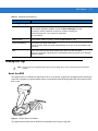
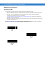
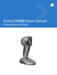
Symbol DS9808-R
Product Reference Guide Supplement
Symbol DS9808-R
Product Reference Guide Supplement
72E-132822-01
Revision A
April 2010
ii
Symbol DS9808-R Product Reference Guide Supplement
© 2010 by Motorola, Inc. All rights reserved.
No part of this publication may be reproduced or used in any form, or by any electrical or mechanical means,
without permission in writing from Motorola. This includes electronic or mechanical means, such as
photocopying, recording, or information storage and retrieval systems. The material in this manual is subject to
change without notice.
The software is provided strictly on an “as is” basis. All software, including firmware, furnished to the user is on
a licensed basis. Motorola grants to the user a non-transferable and non-exclusive license to use each
software or firmware program delivered hereunder (licensed program). Except as noted below, such license
may not be assigned, sublicensed, or otherwise transferred by the user without prior written consent of
Motorola. No right to copy a licensed program in whole or in part is granted, except as permitted under
copyright law. The user shall not modify, merge, or incorporate any form or portion of a licensed program with
other program material, create a derivative work from a licensed program, or use a licensed program in a
network without written permission from Motorola. The user agrees to maintain Motorola’s copyright notice on
the licensed programs delivered hereunder, and to include the same on any authorized copies it makes, in
whole or in part. The user agrees not to decompile, disassemble, decode, or reverse engineer any licensed
program delivered to the user or any portion thereof.
Motorola reserves the right to make changes to any software or product to improve reliability, function, or
design.
Motorola does not assume any product liability arising out of, or in connection with, the application or use of
any product, circuit, or application described herein.
No license is granted, either expressly or by implication, estoppel, or otherwise under any Motorola, Inc.,
intellectual property rights. An implied license only exists for equipment, circuits, and subsystems contained in
Motorola products.
MOTOROLA and the Stylized M Logo and Symbol and the Symbol logo are registered in the US Patent &
Trademark Office. Bluetooth is a registered trademark of Bluetooth SIG. Microsoft, Windows and ActiveSync
are either registered trademarks or trademarks of Microsoft Corporation. All other product or service names
are the property of their respective owners.
Motorola, Inc.
One Motorola Plaza
Holtsville, New York 11742-1300
http://www.motorola.com/enterprisemobility
Warranty
For the complete Motorola hardware product warranty statement, go to:
http://www.motorola.com/enterprisemobility/warranty.
iii
Revision History
Changes to the original manual are listed below:
Change
Date
-01 Rev A
4/2010
Description
Initial release
iv
Symbol DS9808-R Product Reference Guide Supplement
Table of Contents
About This Guide
Introduction ....................................................................................................................
Configurations................................................................................................................
Availability ................................................................................................................
Upgrading a DS9808 to DS9808-R..........................................................................
Chapter Descriptions .....................................................................................................
Notational Conventions..................................................................................................
Related Documents .......................................................................................................
Service Information........................................................................................................
vii
vii
viii
viii
ix
x
x
xi
Chapter 1: Getting Started
Introduction ...................................................................................................................
Unpacking .....................................................................................................................
Interfaces ......................................................................................................................
Setting Up the Digital Scanner ......................................................................................
Connecting the Interface Cable ..............................................................................
Connecting to a USB Interface ...............................................................................
Connecting to an RS-232/SSI Interface ..................................................................
Connecting to an IBM 468X/469X Interface ............................................................
1-1
1-2
1-2
1-2
1-2
1-3
1-4
1-5
Chapter 2: Data Capture
Introduction ...................................................................................................................
Beeper Definitions ........................................................................................................
LED Definitions .............................................................................................................
Reading RFID Tags ......................................................................................................
Hands-Free RFID ....................................................................................................
Hand-Held RFID .....................................................................................................
RFID Reading Recommendations ..........................................................................
2-1
2-2
2-4
2-5
2-5
2-6
2-6
Chapter 3: RFID Preferences
Introduction ...................................................................................................................
Scanning Sequence Examples .....................................................................................
Errors While Scanning ..................................................................................................
RFID Preferences Parameter Defaults .........................................................................
RFID Preferences .........................................................................................................
3-1
3-2
3-2
3-2
3-4
vi
Symbol DS9808-R Product Reference Guide Supplement
Multifunction Mode Triggering .................................................................................
Host Triggering .......................................................................................................
RFID Beeper Tone ..................................................................................................
RFID Same Tag Timeout ........................................................................................
RFID Automatic Presentation Mode .......................................................................
RFID Trigger Mode .................................................................................................
RFID Data Transmission Format ............................................................................
RFID Transmit Raw with PC Bytes .........................................................................
RFID Transmit Unknown Tag Data .........................................................................
RFID Antenna Selection .........................................................................................
RFID Antenna Power in Hand-Held Mode ..............................................................
RFID Antenna Power in Hands-Free Mode ............................................................
RFID Hands-Free Idle Timeout ...............................................................................
3-4
3-9
3-11
3-12
3-14
3-15
3-16
3-20
3-20
3-21
3-22
3-24
3-26
Chapter 4: SSI Interface
Introduction ...................................................................................................................
Simple Serial Interface Default Parameters ..................................................................
SSI Host Parameters ....................................................................................................
Baud Rate ...............................................................................................................
Parity .......................................................................................................................
Check Parity ............................................................................................................
Software Handshaking ............................................................................................
Host RTS Line State ...............................................................................................
Decode Data Packet Format ...................................................................................
Host Serial Response Time-out ..............................................................................
Host Character Time-out .........................................................................................
Multipacket Option ..................................................................................................
Interpacket Delay ....................................................................................................
Event Reporting ............................................................................................................
Decode Event .........................................................................................................
Boot Up Event .........................................................................................................
Parameter Event .....................................................................................................
4-1
4-2
4-3
4-3
4-4
4-5
4-5
4-6
4-6
4-7
4-8
4-9
4-10
4-11
4-11
4-12
4-12
Chapter 5: Advanced Data Formatting
Introduction ................................................................................................................... 5-1
Chapter 6: Maintenance & Technical Specifications
Introduction ...................................................................................................................
Maintenance .................................................................................................................
Troubleshooting ............................................................................................................
Technical Specifications ...............................................................................................
6-1
6-1
6-2
6-3
Appendix A: Numeric Bar Codes
Numeric Bar Codes ...................................................................................................... A-1
Cancel ........................................................................................................................... A-2
Index
Tell Us What You Think...
About This Guide
Introduction
The Symbol DS9808-R Product Reference Guide Supplement provides the unique reading and programming
procedures for the DS9808-R (DS9808 with RFID) digital scanner. This guide is intended as a supplement to the
Symbol DS9808 Product Reference Guide, p/n 72E-112999-xx. For information and procedures common to the
DS9808 series of products, refer to the Product Reference Guide.
Configurations
This guide addresses the following DS9808-R configurations.
Configuration
Scan Range
DL
Parsing
RFID
Availability
DS9808-SR00007C1WR
Standard
No
902 – 928 Mhz
United States
DS9808-SR00007C2WR
Standard
No
902 – 928 Mhz
Canada, Mexico
DS9808-DL00007C1WR
Standard
Yes
902 – 928 Mhz
United States
DS9808-LR20007C1WR
Long
No
902 – 928 Mhz
United States
DS9808-LR20007C2WR
Long
No
902 – 928 Mhz
Canada, Mexico
DS9808-LL20007C1WR
Long
Yes
902 – 928 Mhz
United States
viii
Symbol DS9808-R Product Reference Guide Supplement
Availability
The DS9808-R is only available for the countries listed below.
NOTE
This list may be updated if other countries are added. Check with your local Motorola sales representative
for the latest information on availability in your country.
Configuration
Countries Supported
DS9808-SR00007C1WR
United States
DS9808-SR00007C2WR
Canada, Mexico
DS9808-DL00007C1WR
United States
DS9808-LR20007C1WR
United States
DS9808-LR20007C2WR
Canada, Mexico
DS9808-LL20007C1WR
United States
Upgrading a DS9808 to DS9808-R
DS9808 customers in countries listed above can upgrade certain DS9808 models to DS9808-R. Motorola's repair
centers perform the upgrades, ensuring like-new factory performance. Contact Motorola Enterprise Mobility
Support at (800) 653-5350 for upgrade pricing and instructions.
The following DS9808 models can be upgraded to DS9808-R:
DS9808 Model
Can be upgraded to:
DS9808-LR20007CRWR
DS9808-LR20007C1WR, DS9808-LR20007C2WR
DS9808-LL20007CRWR
DS9808-LL20007C1WR
Review the following differences between the DS9808 and the DS9808-R before deciding to upgrade.
Feature
DS9808
DS9808-R
Multiple Interfaces Supported
USB, RS-232, RS-485 (port 9b, 5b,
and 17b), keyboard wedge
USB, RS-232, RS-485 (port 9b and
5b). No keyboard wedge support.
Optional DC Power Supply
5 VDC power supply required for
RS-232 and keyboard wedge only
12 VDC power supply required for
USB (series A only), RS-232, and
RS-485 (port 5b only)
Wall Mount Bracket
Supported
Not supported
Checkpoint EAS
EAS optional
EAS not supported
About This Guide
ix
Chapter Descriptions
Topics covered in this guide are as follows:
• Chapter 1, Getting Started provides a product overview, unpacking instructions, and cable connection
information.
• Chapter 2, Data Capture describes parts of the RFID digital scanner, beeper and LED definitions, and how to
use the scanner to read tags.
• Chapter 3, RFID Preferences describes RFID preference features and provides programming bar codes for
selecting these features.
• Chapter 4, SSI Interface describes how to set up the RFID digital scanner with a Simple Serial Interface (SSI)
host.
• Chapter 5, Advanced Data Formatting briefly describes ADF, a means of customizing data before
transmission to the host device, and includes a reference to the ADF Programmer Guide.
• Chapter 6, Maintenance & Technical Specifications provides information on how to care for the RFID digital
scanner, troubleshooting, and technical specifications.
• Appendix A, Numeric Bar Codes includes the numeric bar codes to scan for parameters requiring specific
numeric values.
x
Symbol DS9808-R Product Reference Guide Supplement
Notational Conventions
The following conventions are used in this document:
• Italics are used to highlight the following:
• Chapters and sections in this and related documents
• Dialog box, window and screen names
• Drop-down list and list box names
• Check box and radio button names
• Bold text is used to highlight the following:
• Key names on a keypad
• Button names on a screen.
• bullets (•) indicate:
• Action items
• Lists of alternatives
• Lists of required steps that are not necessarily sequential
• Sequential lists (e.g., those that describe step-by-step procedures) appear as numbered lists.
• Throughout the programming bar code menus, asterisks (*) are used to denote default parameter settings.
* Indicates Default
*Baud Rate 9600
Feature/Option
Related Documents
• Symbol DS9808 Product Reference Guide, p/n 72E-112999-xx - provides detailed setup and programming
information for the Symbol DS9808 digital scanner.
• Symbol DS9808-R Quick Start Guide, p/n 72-125703-xx - provides general information for getting started
with the Symbol DS9808-R digital scanner, and includes basic set up and operation instructions.
• Advanced Data Formatting Programmer Guide, p/n 72E-69680-xx - provides information on ADF, a means of
customizing data before transmission to a host.
For the latest version of this guide and all Symbol guides, go to:
http://www.motorola.com/enterprisemobility/manuals.
About This Guide
xi
Service Information
If you have a problem with your equipment, contact Motorola Enterprise Mobility support for your region. Contact
information is available at: http://www.motorola.com/enterprisemobility/contactsupport.
When contacting Enterprise Mobility support, please have the following information available:
• Serial number of the unit
• Model number or product name
• Software type and version number
Motorola responds to calls by e-mail, telephone or fax within the time limits set forth in service agreements.
If your problem cannot be solved by Motorola Enterprise Mobility Support, you may need to return your equipment
for servicing and will be given specific directions. Motorola is not responsible for any damages incurred during
shipment if the approved shipping container is not used. Shipping the units improperly can possibly void the
warranty.
If you purchased your Enterprise Mobility business product from a Motorola business partner, please contact that
business partner for support.
xii
Symbol DS9808-R Product Reference Guide Supplement
Chapter 1 Getting Started
Introduction
The Symbol DS9808-R digital scanner combines 1D and 2D bar code scanning and superior RFID tag reading and
transfer with a light-weight, hands-free/hand-held design. The digital scanner’s built-in stand seamlessly
accommodates both counter-top and hand-held use. Whether in hands-free (presentation) or hand-held mode, the
digital scanner ensures comfort and ease of use for extended periods of time.
Figure 1-1 Symbol DS9808-R Digital Scanner
1-2
Symbol DS9808-R Product Reference Guide Supplement
Unpacking
Remove the digital scanner from its packing and inspect it for damage. If the scanner was damaged in transit,
contact Motorola Enterprise Mobility Support. See page xi for contact information. KEEP THE PACKING. It is the
approved shipping container; use this to return the equipment for servicing.
Interfaces
The DS9808-R digital scanner supports the following interfaces. Refer to the Symbol DS9808 Product Reference
Guide for more information.
• USB
• Standard RS-232
• IBM 468X/469X
• Simple Serial Interface (SSI) (RFID configuration only)
Setting Up the Digital Scanner
Connecting the Interface Cable
NOTE
1.
Different interfaces require different cables. The connectors illustrated in the following sections are
examples only. Connectors vary from those illustrated, but the steps to connect the digital scanner are the
same.
Plug the interface cable modular connector into the cable interface port on the bottom of the digital scanner’s
base.
Interface cable port
Clip
To host
Interface cable modular connector
Figure 1-2 Installing the Interface Cable
2.
Gently tug the cable to ensure the connector is secure.
Getting Started
1-3
Removing the Interface Cable
1.
Press the cable’s modular connector clip through the access slot in the digital scanner’s base.
Figure 1-3 Removing the Cable
2.
Carefully slide out the cable.
3.
Follow the steps for Connecting the Interface Cable to connect a new cable.
Connecting to a USB Interface
1.
Plug the USB interface cable series A connector in the USB host or hub, or plug the Plus Power connector into
an available port on the IBM SurePOS terminal.
2.
If not using a PowerPlus cable, connect external power:
a.
Plug the power supply adapter cable into the power jack on the interface cable.
b.
Connect the other end of the power supply adapter cable to the power supply.
c.
Plug the power supply into an AC outlet.
Power Supply
Power Supply Adapter Cable
USB Interface Cable
USB Connector
Figure 1-4 USB Connection
1-4
Symbol DS9808-R Product Reference Guide Supplement
3.
Select the USB device type by scanning the appropriate bar code from the Symbol DS9808 Product Reference
Guide.
4.
On first installation when using Windows, the software prompts to select or install the Human Interface Device
driver. To install this driver, provided by Windows, click Next through all the choices and click Finished on the
last choice. The digital scanner powers up during this installation.
Connecting to an RS-232/SSI Interface
1.
Connect the RS-232/SSI interface cable to the serial port on the host.
2.
Connect the power supply adapter cable to the serial connector end of the interface cable.
3.
Connect the other end of the power supply adapter cable to the power supply.
4.
Plug the power supply into an AC outlet.
RS-232/SSI Interface Cable
Power Supply
Serial Connector
Power Supply Adapter Cable
Figure 1-5 RS-232 Direct Connection
5.
Select the RS-232 host type by scanning the appropriate bar code from the Symbol DS9808 Product
Reference Guide, or if using SSI scan the appropriate baud rate bar code from Baud Rate on page 4-3 that
matches the host’s baud rate setting.
Getting Started
1-5
Connecting to an IBM 468X/469X Interface
1.
Connect the IBM 46XX interface cable to the appropriate port on the host (Port 9B or Port 5B).
2.
If using Port 5B, connect power (Port 9B does not require a separate power supply):
a.
Connect the power supply adapter cable to the power jack on the interface cable.
b.
Connect the other end of the power supply adapter cable to the power supply.
c.
Plug the power supply into an AC outlet.
Power Supply
IBM 46XX
Interface Cable
Power Supply
Adapter Cable
IBM 46XX
Interface Cable
Port 5B
Port 9B
Figure 1-6 IBM 468X/469X Connection
3.
Select the port address by scanning the appropriate bar code from Symbol DS9808 Product Reference Guide.
1-6
Symbol DS9808-R Product Reference Guide Supplement
Chapter 2 Data Capture
Introduction
This chapter provides beeper and LED definitions, and techniques involved in reading RFID tags.
LED
Scan Window
Interface cable port
Trigger A
Trigger B
RFID LED
ID
RF
RFID Module
Figure 2-1 Parts
2-2
Symbol DS9808-R Product Reference Guide Supplement
Beeper Definitions
The digital scanner issues different beep sequences and patterns to indicate status. Table 2-1 defines beep
sequences that occur during both normal scanning and while programming the digital scanner.
Table 2-1 Beeper Definitions
Beeper Sequence
Indication
Standard Use
Low/medium/high beeps
Power up.
Short high beep
A bar code symbol was decoded (if decode beeper is enabled).
4 long low beeps
Transmission error.
5 low beeps
Conversion or format error.
Low/low/low/extra low beeps
RS-232 receive error.
High beep
The digital scanner detected a <BEL> character over RS-232.
RFID
Medium-high (two-tone) beep
An RFID tag was read (if RFID read beeper is enabled).
High-medium/low/low beeps
Unexpected RFID indication.
Image Capture
Low beep
Snapshot mode started or completed.
High/low beeps
Snapshot mode timed out.
Parameter Menu Scanning
Low/high beeps
Input error; incorrect bar code, programming sequence, or Cancel scanned.
High/low beeps
Keyboard parameter selected. Enter value using numeric bar codes.
High/low/high/low beeps
Successful program exit with change in parameter setting.
Code 39 Buffering
High/low beeps
New Code 39 data was entered into the buffer.
3 long high beeps
Code 39 buffer is full.
High/low/high beeps
The Code 39 buffer was erased.
Low/high/low beeps
The Code 39 buffer was erased or there was an attempt to clear or transmit an
empty buffer.
Low/high beeps
A successful transmission of buffered data.
Data Capture
2-3
Table 2-1 Beeper Definitions (Continued)
Beeper Sequence
Indication
Macro PDF
2 low beeps
MPDF sequence buffered.
2 long low beeps
File ID error. A bar code not in the current MPDF sequence was scanned.
3 long low beeps
Out of memory. There is not enough buffer space to store the current MPDF
symbol.
4 long low beeps
Bad symbology. Scanned a 1D or 2D bar code in a MPDF sequence, a duplicate
MPDF label, a label in an incorrect order, or trying to transmit an empty or illegal
MPDF field.
5 long low beeps
Flushing MPDF buffer.
Fast warble beep
Aborting MPDF sequence.
Low/high beeps
Flushing an already empty MPDF buffer.
Host Specific
USB only
4 short high beeps
The digital scanner has not completed initialization. Wait several seconds and
scan again.
Low/medium/high beeps
upon scanning a USB device
type
Communication with the host must be established before the digital scanner can
operate at the highest power level.
Low/medium/high beeps
occur more than once
The USB host can put the digital scanner in a state where power to the scanner is
cycled on and off more than once. This is normal and usually happens when the
PC cold boots.
RS-232 only
1 short high beep
A <BEL> character is received and Beep on <BEL> is enabled.
2-4
Symbol DS9808-R Product Reference Guide Supplement
LED Definitions
In addition to beep sequences, the digital scanner uses a two-color LED to indicate status. Table 2-2 defines LED
colors that display during scanning.
Table 2-2 Standard LED Definitions
LED
Indication
Hand-Held Scanning Standard Use
Green
A bar code was successfully decoded or an RFID tag was read.
Red
Transmission error, conversion or format error, or RS-232 receive error.
Off
No power is applied to the digital scanner, or the scanner is on and ready to scan.
Hands-Free (Presentation) Scanning Standard Use
Green
The scanner is on and ready to scan.
Momentarily Off
A bar code was successfully decoded or an RFID tag was read.
Red
Transmission error, conversion or format error, or RS-232 receive error.
Off
No power is applied to the digital scanner, or the scanner is in low power mode.
RFID LED (on the RFID module)
Off
The RFID module is inactive.
On
The RFID module is ready to read tags.
Momentarily Off
The RFID module read a tag.
Slow blinking
The RFID module is polling for new tags.
Parameter Programming
Green
Number expected. Enter value using numeric bar codes.
Successful program exit with change in parameter setting.
Red
Input error: incorrect bar code, programming sequence, or Cancel scanned.
Data Capture
2-5
Table 2-2 Standard LED Definitions
LED
Indication
ADF Programming
Green
Enter another digit. Add leading zeros to the front if necessary.
Enter another alphabetic character or scan the End of Message bar code.
All criteria or actions cleared for current rule, continue entering rule.
Delete last saved rule. The current rule is left intact.
All rules deleted.
Blinking Green
Enter another criterion or action, or scan the Save Rule bar code.
Green after Blinking
Rule saved. Rule entry mode exited.
Cancel rule entry. Rule entry mode exited because of an error or the user asked to exit
rule entry.
Red
Out of rule memory. Erase some existing rules, then try to save rule again.
Entry error, wrong bar code scanned, or criteria/action list is too long for a rule. Re-enter
criterion or action.
Reading RFID Tags
NOTE
The top surface of the digital scanner base may feel slightly warm. This is normal and does not indicate a
problem.
Hands-Free RFID
The digital scanner is in hands-free mode when it sits on a countertop. In this mode, the digital scanner operates in
continuous (constant-on) mode by default, where it automatically reads RFID tags within the radio frequency (RF)
field of view.
Figure 2-2 RFID in Hands-Free Mode
The digital scanner beeps and the RFID LED momentarily turns off upon a tag read.
2-6
Symbol DS9808-R Product Reference Guide Supplement
If the digital scanner does not observe any new RFID tags within the RFID Hands-Free Idle Timeout on page 3-26,
it reduces power consumption by polling for tags once a second.
Hand-Held RFID
In hand-held mode, press the trigger to read all RFID tags within the RF field of view. Release the trigger to stop
reading tags.
Figure 2-3 RFID in Hand-Held Mode
The digital scanner beeps and the RFID LED momentarily turns off upon a tag read.
DS9808-LR/LL Multifunction Trigger
The DS9808-LR/LL digital scanner includes a multifunction trigger which you can program to quickly switch
between imaging, laser scanning, and/or RFID reading. See Multifunction Mode Triggering on page 3-4 for more
information.
RFID Reading Recommendations
• When holding the digital scanner, don’t allow your fingers to get any closer to the antenna structure (in the
base) than necessary. This can shield the tag from the RFID reader and reduce performance.
• When reading multiple items, it is highly recommended to pass one item at a time past the digital scanner.
While you can pass many items at a time by the digital scanner, it can be difficult to correlate multiple beeps
to multiple items at once and errors can occur.
• Use care when reading metal items. The metals can reduce tag read range or in some cases shield the tag
from the reader. Always correlate the read beep with the item the digital scanner is reading (as with bar code
scanning).
• Never hold the RFID tag of the item the digital scanner is reading. Instead, hold the item and let the tag hang
free.
• Orient the tag toward the digital scanner if it has difficulty reading the tag. Waving often helps.
• If all else fails, scan the item’s bar code.
Chapter 3 RFID Preferences
Introduction
NOTE
The RFID module is not available in all countries. Contact a Motorola sales representative for more
information.
You can program the digital scanner to perform various functions, or activate different features. This chapter
describes RFID preference features and provides programming bar codes for selecting these features. To program
other features, refer to the Symbol DS9808 Product Reference Guide.
The digital scanner ships with the settings in RFID Preferences Parameter Defaults on page 3-2. If the default
values suit requirements, programming is not necessary.
To set feature values, scan a single bar code or a short bar code sequence. The settings are stored in non-volatile
memory and are preserved even when you power down the digital scanner.
NOTE
Most computer monitors allow scanning the bar codes directly on the screen. When scanning from the
screen, be sure to set the document magnification to a level where you can see the bar code clearly, and
bars and/or spaces are not merging.
If not using a USB cable, select a host type after the power-up beeps sound. Refer to the Symbol DS9808 Product
Reference Guide for specific host information. This is only necessary upon the first power-up when connecting to a
new host.
To return all features to default values, scan the Set Default parameter in the Symbol DS9808 Product Reference
Guide. Throughout the programming bar code menus, asterisks (*) indicate default values.
Feature/Option
* Indicates Default
*Medium to High Tone (2-Tone)
(04h)
Option Hex Value
3-2
Symbol DS9808-R Product Reference Guide Supplement
Scanning Sequence Examples
In most cases scanning one bar code sets the parameter value. For example, to turn the beeper off, scan the Off
bar code under RFID Beeper Tone on page 3-11. The digital scanner issues a fast warble beep and the LED turns
green, signifying a successful parameter entry.
Other parameters require scanning several bar codes. See these parameter descriptions for this procedure.
Errors While Scanning
Unless otherwise specified, to correct an error during a scanning sequence, just re-scan the correct parameter.
RFID Preferences Parameter Defaults
Table 3-1 lists the defaults for RFID preferences parameters. To change the default values, scan the appropriate
bar codes in this guide. These new values replace the standard default values in memory. To recall the default
parameter values, scan the Set Default parameter in the Symbol DS9808 Product Reference Guide.
Table 3-1
RFID Preferences Parameter Defaults
Parameter
Parameter
Number
Default
Page
Number
RFID Preferences
Multifunction Triggering
Single Trigger
3-4
Trigger A
F1h 77h
Laser Preferred Decoding
3-4
Trigger B
F1h 78h
RFID Reading
3-6
Trigger A + B
F1h 79h
Ignore
3-7
Laser Preferred Timeout
F1h 7Dh
1.5 seconds
3-8
Dual Trigger Debounce Timeout
F1h 7Ah
0.05 seconds
3-8
Dual Trigger Processing
F1h 7Bh
Wait
3-9
Host Trigger Mode
F1h 7Ch
Imager Decoding
3-9
RFID Beeper Tone
F1h 7Fh
Medium to High Tone (2-Tone)
3-11
RFID Same Tag Timeout
F1h 80h
5 Minutes
3-12
RFID Automatic Presentation Mode
F1h 81h
Hands-Free Only
3-14
RFID Trigger Mode
F1h 82h
Continuous
3-15
RFID Data Transmission Format
F1h 83h
Raw
3-16
RFID Transmit Raw with PC Bytes
F1h CAh
Disable
3-20
RFID Transmit Unknown Tag Data
F1h C5h
Transmit
3-20
RFID Antenna Selection
F1h C6h
Both
3-21
RFID Preferences
Table 3-1
3-3
RFID Preferences Parameter Defaults (Continued)
Parameter
Parameter
Number
Default
Page
Number
RFID Antenna Power in Hand-Held Mode
F1h C7h
Level 5
3-22
RFID Antenna Power in Hands-Free Mode
F1h C8h
Level 5
3-24
RFID Hands-Free Idle Timeout
F1h C9h
5 Minutes
3-26
3-4
Symbol DS9808-R Product Reference Guide Supplement
RFID Preferences
The parameters in this chapter control RFID behavior.
Multifunction Mode Triggering
You can set trigger options for each of the digital scanner’s trigger positions. For example, set Trigger A (pressed
with your index finger) to imager decoding, set Trigger B (pressed with your middle finger) for laser decoding, and
set Trigger A + B (pressed with both fingers) for RFID reading.
The default operation is single trigger, so if you do not assign values to each trigger option (or assign Trigger A
only), Trigger B operates the same as Trigger A, and a dual trigger pull is ignored.
Select one of the following functions for each trigger using the bar codes on the next few pages:
• Laser Preferred Decoding - Programs the trigger for decoding using the laser engine first, then the imager
if a decode does not occur. Refer to the Symbol DS9808 Product Reference Guide for more information.
DS9808-SR/DL models do not support this option.
• Imager Decoding - Programs the trigger for decoding using the imager engine.
• RFID Reading - Programs the trigger for reading RFID tags.
• Imager Plus RFID - A trigger pull attempts decode using the imager engine, and turns on the optional RFID
reader, if available, to read RFID tags.
• Laser Preferred Plus RFID - A trigger pull attempts decode using the laser engine first, then the imager if a
decode does not occur, and also turns on the RFID reader to read RFID tags. DS9808-SR/DL models do not
support this option.
• Laser Only Decoding - Programs the trigger for decoding using the laser engine only. DS9808-SR/DL
models do not support this option.
• Set to Trigger A Value (Trigger B Only) - Sets Trigger B to the same value as Trigger A. This allows you to
automatically program Trigger B upon selecting the function of Trigger A.
• Ignore Dual Trigger Pull (Trigger A+B Only) - Uses the mode of the first trigger pull only. This increases
triggering efficiency when the dual trigger is not needed.
Trigger A
Trigger B
Figure 3-1 Trigger Locations
RFID Preferences
Trigger A
Parameter # F1h 77h
NOTE
You cannot set Trigger A to RFID Reading if Trigger B is set to either RFID Reading or Set to Trigger A
Value. In addition, laser options are not available for DS9808-SR/DL models.
*Laser Preferred Decoding
(00h)
**Imager Decoding
(01h)
RFID Reading
(02h)
Imager Plus RFID
(03h)
Laser Preferred Plus RFID
(04h)
Laser Only Decoding
(06h)
*Default for DS9808-LR/LL
**Default for DS9808-SR/DL
3-5
3-6
Symbol DS9808-R Product Reference Guide Supplement
Trigger B
Parameter # F1h 78h
NOTE
You cannot set Trigger B to RFID Reading or Set to Trigger A Value if Trigger A is set to RFID Reading.
In addition, laser options are not available for DS9808-SR/DL models.
Laser Preferred Decoding
(00h)
Imager Decoding
(01h)
*RFID Reading
(02h)
(*Default when used with RFID)
Imager Plus RFID
(03h)
Laser Preferred Plus RFID
(04h)
Set to Trigger A Value
(05h)
Laser Only Decoding
(06h)
RFID Preferences
Trigger A+B
Parameter # F1h 79h
NOTE
Laser options are not available for DS9808-SR/DL models.
Laser Preferred Decoding
(00h)
Imager Decoding
(01h)
RFID Reading
(02h)
Imager Plus RFID
(03h)
Laser Preferred Plus RFID
(04h)
*Ignore Dual Trigger Pull (Use Mode of First Trigger Pull)
(05h)
Laser Only Decoding
(06h)
3-7
3-8
Symbol DS9808-R Product Reference Guide Supplement
Laser Preferred Timeout
Parameter # F1h 7Dh
If Multifunction Mode Triggering is set to Laser Preferred Decoding, use this parameter to set the time period that
the laser remains on before using the imager if a decode does not occur.
To set the timeout, scan the bar code below, followed by two bar codes from Appendix A, Numeric Bar Codes that
correspond to the desired time in the range of 0.1 to 9.9 seconds. To correct an error or change the selection, scan
Cancel on page A-2. The default is 1.5 seconds.
Laser Preferred Timeout
Dual Trigger Debounce Timeout
Parameter # F1h 7Ah
Set a time period in which both triggers must be pulled in order for the digital scanner to recognize this as a dual
trigger pull. In other words, if you pull Trigger A, then Trigger B after this timeout expires, the digital scanner
behaves as if you pulled Trigger A only.
To set the timeout, scan the bar code below, followed by two bar codes from Appendix A, Numeric Bar Codes that
correspond to the desired time in the range of 0.00 to 0.99 seconds. Enter a trailing zero for single digit numbers.
For example, to set a Debounce Timeout of 0.50 seconds, scan the bar code below, then scan the 5 and 0 bar
codes. To correct an error or change the selection, scan Cancel on page A-2.
The default is 0.05 seconds.
Dual Trigger Debounce Timeout
RFID Preferences
3-9
Dual Trigger Processing
Parameter # F1h 7Bh
Select whether the digital scanner processes the first trigger pull immediately, or waits until the Dual Trigger
Debounce Timeout expires before processing. If the second trigger pull occurs within the timeout, the scanner
switches to the combination function.
Process Immediately
*Wait for Timeout Before Processing
Host Triggering
Parameter # F1h 7Ch
Set an option for host-initiated triggering:
• Laser Preferred Decoding - Programs the host trigger for decoding using the laser engine first, then the
imager if a decode does not occur.
• Imager Decoding - Programs the trigger for decoding using the imager engine.
• RFID Reading - Programs the trigger for reading RFID tags.
• Imager Plus RFID - A trigger pull attempts decode using the imager engine, and turns on the optional RFID
reader, if available, to read RFID tags.
• Laser Preferred Plus RFID - A trigger pull attempts decode using the laser engine first, then the imager if a
decode does not occur, and also turns on the optional RFID reader, if available, to read RFID tags.
• Laser Only Decoding - Programs the trigger for decoding using the laser engine only.
3 - 10 Symbol DS9808-R Product Reference Guide Supplement
Host Triggering (continued)
NOTE
Laser options are not available for DS9808-SR/DL models.
Laser Preferred Decoding
(00h)
*Imager Decoding
(01h)
RFID Reading
(02h)
Imager Plus RFID
(03h)
Laser Preferred Plus RFID
(04h)
Laser Only Decoding
(06h)
RFID Preferences 3 - 11
RFID Beeper Tone
Parameter # F1h 7Fh
To select an RFID read beep tone, scan one of the following bar codes.
Off
(03h)
Low Tone
(02h)
Medium Tone
(01h)
High Tone
(00h)
*Medium to High Tone (2-Tone)
(04h)
3 - 12 Symbol DS9808-R Product Reference Guide Supplement
RFID Same Tag Timeout
Parameter # F1h 80h
If the digital scanner does not observe a group of tags within this timeout period, it removes the tags in the group
from the tag cache. If the digital scanner later reads one of these tags, it reports this as a new tag.
Disable this timeout to report a tag every time the digital scanner sees it. This option is typically used for testing,
and disables the tag cache, affecting both presentation and triggered operation.
Disable
(00h)
2 Seconds
(02h)
10 Seconds
(0Ah)
15 Seconds
(0Bh)
30 Seconds
(0Dh)
1 Minute
(11h)
RFID Preferences 3 - 13
RFID Same Tag Timeout (continued)
*5 Minutes
(15h)
15 Minutes
(1Bh)
1 Hour
(21h)
3 - 14 Symbol DS9808-R Product Reference Guide Supplement
RFID Automatic Presentation Mode
Parameter # F1h 81h
Select one of the following options to configure the digital scanner to continuously read tags (presentation mode)
when you place the scanner on the countertop (hands-free), when you lift it (hand-held), or in both or neither
situation. Note that triggered operation always overrides presentation mode.
Disable
(00h)
*Hands-Free Only
(01h)
Hand-Held Only
(02h)
Always
(03h)
RFID Preferences 3 - 15
RFID Trigger Mode
Parameter # F1h 82h
In hand-held operation, this parameter controls the behavior of a trigger programmed for RFID reading.
• Continuous - the reader reads all tags within range, maintaining the existing tag cache so it does not report
tags already read.
• Single Tag Read - the reader reads and reports only one tag. It maintains the tag cache and reports this tag
regardless of whether it already reported it.
• Continuous Re-Report - the reader reads all tags within range, maintaining the tag cache, and reports each
tag once within this trigger session regardless of whether it already reported it.
• Continuous Flush - the reader flushes the tag cache, reads all tags within range, and reports them as new
tags.
NOTE
To program the trigger for various functions including RFID, see Multifunction Mode Triggering on page 3-4
and Host Triggering on page 3-9.
*Continuous
(00h)
Single Tag
(01h)
Continuous Re-Report
(02h)
Continuous Flush
(03h)
3 - 16 Symbol DS9808-R Product Reference Guide Supplement
RFID Data Transmission Format
Parameter # F1h 83h
This parameter controls the format of the tag's EPC data sent after reading a new tag.
• Raw - the EPC buffer transmits as a hexadecimal string. This format can include the protocol control bytes.
• GS1-128 - for GS1 encoded tags, this option converts EPC data to a GS1-128 bar code (as per the
EPCglobal Tag Data Standards Version 1.4 available at
http://www.epcglobalinc.org/standards/tds/tds_1_4-standard-20080611.pdf). Otherwise, the tag optionally
transmits in raw format or is ignored.
• EPC URI - the EPC data is represented as a Universal Resource Identifier (URI) as defined in the EPCglobal
Tag Data Standards Version 1.4.
See Table 3-2, Table 3-3, and Table 3-4 for transmission format details for the various tag types, and samples for
each. For more information, refer to EPCglobal Tag Data Standards Version 1.4.
*Raw
(00h)
GS1-128
(01h)
EPC URI
(02h)
RFID Preferences 3 - 17
Table 3-2 GS1-128 Transmission Details by EPC Tag Type
EPC Tag Type
Transmission Format
GID
N/A
SGTIN
(01) GTIN (21) Serial Number
SSCC
(00) SSCC
SGLN
(414) GLN (254) GLN-Extension
GRAI
(8003) GRAI Serial Number
GIAI
(8004) GIAI Serial Number
GSRN
(8018) GSRN
GDTI
(253) GDTI
US DoD
N/A
Unknown
N/A
Table 3-3 EPC-URI Transmission Details by EPC Tag Type
EPC Tag Type
Transmission Format
GID
urn:epc:tag:gid-96:<generalMngr>.<objectClass>.<serno>
SGTIN
urn:epc:tag:sgtin-96:<filter>.<company>.<itemRef>.<serialNumber>
SSCC
urn:epc:tag:sscc-96:<filter>.<companyPrefix>.<serialReference>
SGLN
urn:epc:tag:sgln-96:<filter>.<companyPrefix>.<locationReference>.<extention>
GRAI
urn:epc:tag:grai-96:<filter>.<companyPrefix>.<assetType>.<serialNumber>
GIAI
urn:epc:tag:giai-96:<filter>.<companyPrefix>.<individulAssetReference>
GSRN
urn:epc:tag:gsrn-96:<filter>.<companyPrefix>.<serviceReference>
GDTI
urn:epc:tag:gdti-96:<filter>.<companyPrefix>.<documentType>.<serialNumber>
US DoD
urn:epc:tag:usdod-96:<filter>.<govManagedID>.<serialNumber>
Unknown
urn:epc:tag:raw:BitLength.Value
Unknown (non-EPC)
urn:epc:raw:BitLength.AFI.Value
3 - 18 Symbol DS9808-R Product Reference Guide Supplement
Examples
Table 3-4 Transmission Format Examples
EPC Tag Type
GID
SGTIN
SSCC
SGLN
GRAI
GIAI
GSRN
GDTI
US DoD
Format
Example
Raw
3500004D20004D20000004D2
GS1-128
N/A
EPC-URI
urn:epc:tag:gid-96:1234.1234.1234
Raw
3018789004B5A1C0499602D2
GS1-128
(01)11234562345675(21)1234567890
EPC-URI
urn:epc:tag:sgtin-96:0.123456.1234567.1234567890
Raw
310C75BCD150BC614E000000
GS1-128
(00)112345678923456787
EPC-URI
urn:epc:tag:sscc-96:0.123456789.12345678
Raw
320C0BC614E0180000003039
GS1-128
(414)0123456780125(254)12345
EPC-URI
urn:epc:tag:sgln-96:0.012345678.012.12345
Raw
33180C0E400C0E4000003039
GS1-128
(8003)012345012345412345
EPC-URI
urn:epc:tag:grai-96:0.012345.012345.12345
Raw
3400001D6F345400075BCD15
GS1-128
(8004)000123456789123456789
EPC-URI
urn:epc:giai-96:0.000123456789.123456789
Raw
2D00001D6F345404D2000000
GS1-128
(8018)000123456789012343
EPC-URI
urn:epc:tag:gsrn-96:0.000123456789.01234
Raw
2C180C0E4060720000003039
GS1-128
(253)012345012345412345
EPC-URI
urn:epc:tag:gdti-96:0.012345.012345.12345
Raw
2F0414243313233000003039
GS1-128
N/A
EPC-URI
urn:epc:tag:usdod-96:0.ABC123.12345
Note: Parentheses appear in examples only for readability.
RFID Preferences 3 - 19
Table 3-4 Transmission Format Examples (Continued)
EPC Tag Type
Unknown
Unknown (non-EPC)
Format
Example
Raw
1234567890ABCDEF01234567
GS1-128
N/A
EPC-URI
urn:epc:raw:96.x1234567890ABCDEF01234567
Raw with PC Bytes
31231234567890ABCDEF00000002
EPC-URI
urn:epc:raw:96.x23.x1234567890ABCDEF00000002
Note: Parentheses appear in examples only for readability.
3 - 20 Symbol DS9808-R Product Reference Guide Supplement
RFID Transmit Raw with PC Bytes
Parameter # F1h CAh
When transmitting RFID tags in raw format, this parameter determines whether to include the Protocol Control
(PC) bytes of the EPC data. This is useful when reading non-EPC encoded tags. Refer to EPCglobal Tag Data
Standards Version 1.4 available at http://www.epcglobalinc.org/standards/tds/tds_1_4-standard-20080611.pdf,
section 3.2.1 EPC Memory Contents.
Enable
(01h)
*Disable
(00h)
RFID Transmit Unknown Tag Data
Parameter # F1h C5h
When transmitting RFID tags in GS1-128 format, if the digital scanner can not translate the tag (i.e., it is not GS1
encoded), it can either report the tag in raw format or ignore it.
Ignore
(00h)
*Transmit in Raw Format
(01h)
RFID Preferences 3 - 21
RFID Antenna Selection
Parameter # F1h C6h
Use this parameter to select reading RFID tags using the horizontally oriented antenna, the vertically oriented
antenna, or both.
*Both
(00h)
Horizontal
(01h)
Vertical
(02h)
3 - 22 Symbol DS9808-R Product Reference Guide Supplement
RFID Antenna Power in Hand-Held Mode
Parameter # F1h C7h
This parameter controls the antenna RF power when operated in hand-held mode. Table 3-5 lists the levels and the
associated range as a percent of the baseline range. The baseline range is the range that results when the power
level is set to the maximum level of 7, and can vary depending on the environment, tag sensitivity, and orientation.
Table 3-5 Antenna Power Levels in Hand-Held Mode
Level
Power (dBm)
Range
(% of Baseline)
1
5
12%
2
8
18%
3
11
25%
4
14
35%
5
17
50%
6
20
67%
7
24
100%
NOTE
Baseline can vary depending on environment, tag sensitivity, and orientation.
RFID Preferences 3 - 23
RFID Antenna Power in Hand-Held Mode (continued)
Level 1
(01h)
Level 2
(02h)
Level 3
(03h)
Level 4
(04h)
*Level 5
(05h)
Level 6
(06h)
Level 7
(07h)
3 - 24 Symbol DS9808-R Product Reference Guide Supplement
RFID Antenna Power in Hands-Free Mode
Parameter # F1h C8h
This parameter controls the antenna RF power when operated in hands-free mode. Table 3-6 lists the levels and
the associated range as a percent of the baseline range. The baseline range is the range that results when the
power level is set to the maximum level of 7, and can vary depending on the environment, tag sensitivity, and
orientation.
Table 3-6 Antenna Power Levels in Hands-Free Mode
Level
Power (dBm)
Range
(% of Baseline)
1
5
12%
2
8
18%
3
11
25%
4
14
35%
5
17
50%
6
20
67%
7
24
100%
NOTE
Baseline can vary depending on environment, tag sensitivity, and orientation.
RFID Preferences 3 - 25
RFID Antenna Power in Hands-Free Mode (continued)
Level 1
(01h)
Level 2
(02h)
Level 3
(03h)
Level 4
(04h)
*Level 5
(05h)
Level 6
(06h)
Level 7
(07h)
3 - 26 Symbol DS9808-R Product Reference Guide Supplement
RFID Hands-Free Idle Timeout
Parameter # F1h C9h
This parameter sets the idle timeout in hands-free mode. If the digital scanner does not observe any new RFID
tags within this timeout, it reduces power consumption by polling for tags once a second.
Disable
(00h)
2 Seconds
(02h)
10 Seconds
(0Ah)
15 Seconds
(0Bh)
30 Seconds
(0Dh)
1 Minute
(11h)
RFID Preferences 3 - 27
RFID Hands-Free Idle Timeout (continued)
*5 Minutes
(15h)
15 Minutes
(1Bh)
1 Hour
(21h)
3 - 28 Symbol DS9808-R Product Reference Guide Supplement
Chapter 4 SSI Interface
Introduction
When connected to a a Simple Serial Interface (SSI) host, program the digital scanner via bar code menu or SSI
host commands.
Throughout the programming bar code menus, asterisks (*) indicate default values.
* Indicates Default
*Baud Rate 9600
Feature/Option
(06h)
Option Hex Value for
programming via SSI
command
NOTE
Most computer monitors allow scanning the bar codes directly on the screen. When scanning from the
screen, be sure to set the document magnification to a level where you can see the bar code clearly, and
bars and/or spaces are not merging.
4-2
Symbol DS9808-R Product Reference Guide Supplement
Simple Serial Interface Default Parameters
Table 4-1 lists the defaults for the SSI host. There are two ways to change the default values:
• Scan the appropriate bar codes in this guide. These new values replace the standard default values in
memory. To recall the default parameter values, scan the Set Default parameter in the Symbol DS9808
Product Reference Guide.
• Download data through the device’s serial port using SSI. Hexadecimal parameter numbers appear in this
chapter below the parameter title, and options appear in parenthesis beneath the accompanying bar codes.
See the Simple Serial Interface (SSI) Programmer’s Guide for detailed instructions for changing parameters
using this method.
Table 4-1 SSI Interface Parameter Defaults
Parameter
Parameter
Number
Default
Page
Number
Baud Rate
9Ch
9600
4-3
Parity
9Eh
None
4-4
Check Parity
97h
Enable
4-5
Software Handshaking
9Fh
ACK/NAK
4-5
Host RTS Line State
9Ah
Low
4-6
Decode Data Packet Format
EEh
Send Raw Decode Data
4-6
Host Serial Response Time-out
9Bh
2 sec
4-7
Host Character Time-out
EFh
200 msec
4-8
Multipacket Option
F0h 4Eh
Option 1
4-9
Interpacket Delay
F0h 4Fh
0 ms
4-10
Decode Event
F0h 00h
Disable
4-11
Boot Up Event
F0h 02h
Disable
4-12
Parameter Event
F0h 03h
Disable
4-12
Event Reporting
NOTE
SSI interprets Prefix, Suffix1, and Suffix2 values listed in the default table in the Symbol DS9808 Product
Reference Guide differently than other interfaces. SSI does not recognize key categories, only the 3-digit
decimal value. The default value of 7013 is interpreted as CR only.
SSI Interface
4-3
SSI Host Parameters
Baud Rate
Parameter # 9Ch
Baud rate is the number of bits of data transmitted per second. Set the digital scanner's baud rate to match the data
rate setting of the host device. Otherwise, data may not reach the host or may reach it in distorted form.
To enable the SSI host, scan the appropriate baud rate bar code that matches the baud rate setting of the host
device.
NOTE
The digital scanner does not support baud rates below 9600.
*Baud Rate 9600
(06h)
Baud Rate 19,200
(07h)
38,400
(08h)
57,600
(0Ah)
115,200
(0Bh)
230,400
(0Ch)
4-4
Symbol DS9808-R Product Reference Guide Supplement
Parity
Parameter # 9Eh
A parity check bit is the most significant bit of each ASCII coded character. Select the parity type according to host
device requirements.
• Select Odd parity to set the parity bit to a value 0 or 1, based on data, to ensure that the coded character
contains an odd number of 1 bits.
• Select Even parity to set the parity bit to a value 0 or 1, based on data, to ensure that the coded character
contains an even number of 1 bits.
• If no parity is required, select None.
Odd
(00h)
Even
|(01h)
*None
(04h)
SSI Interface
4-5
Check Parity
Parameter # 97h
Select whether or not to check the parity of received characters. Use the Parity parameter to select the type of
parity.
*Check Parity
(01h)
Do Not Check Parity
(00h)
Software Handshaking
Parameter # 9Fh
This parameter offers control of the data transmission process in addition to that offered by hardware handshaking.
Hardware handshaking is always enabled and cannot be disabled by the user.
• Disable ACK/NAK Handshaking: If you select this option, the digital scanner neither generates nor expects
ACK/NAK handshaking packets.
• Enable ACK/NAK Handshaking: If you select this option, after transmitting data, the digital scanner expects
either an ACK or NAK response from the host. The digital scanner also ACKs or NAKs messages from the
host.
The digital scanner waits up to the programmable Host Serial Response Time-out to receive an ACK or
NAK. If the scanner does not get a response in this time, it resends its data up to two times before discarding
the data and declaring a transmit error.
Disable ACK/NAK
(00h)
*Enable ACK/NAK
(01h)
4-6
Symbol DS9808-R Product Reference Guide Supplement
Host RTS Line State
Parameter # 9Ah
This parameter sets the expected idle state of the Serial Host RTS line.
The SSI Interface is used with host applications which also implement the SSI protocol. However, you can also use
the digital scanner in a "scan-and-transmit" mode to communicate with any standard serial communication
software on a host PC (see Decode Data Packet Format on page 4-6). If transmission errors occur in this mode,
the host PC may be asserting hardware handshaking lines which interfere with the SSI protocol. Scan the Host:
RTS High bar code to address this problem.
*Host: RTS Low
(00h)
Host: RTS High
(01h)
Decode Data Packet Format
Parameter # EEh
This parameter selects whether to transmit decoded data in raw format (unpacketed), or with the packet format
defined by the serial protocol.
Selecting the raw format disables ACK/NAK handshaking for decode data.
*Send Raw Decode Data
(00h)
Send Packeted Decode Data
(01h)
SSI Interface
4-7
Host Serial Response Time-out
Parameter # 9Bh
This parameter specifies how long the digital scanner waits for an ACK or NAK before resending. Also, if the digital
scanner wants to send, and the host was already granted permission to send, the digital scanner waits for the
designated time-out before declaring an error.
To set the delay period (options are 2, 5, 7.5, or 9.9 seconds), scan one of the following bar codes.
NOTE
Other values are available via SSI command.
*Low - 2 Seconds
(14h)
Medium - 5 Seconds
(32h)
High - 7.5 Seconds
(4Bh)
Maximum - 9.9 Seconds
(63h)
4-8
Symbol DS9808-R Product Reference Guide Supplement
Host Character Time-out
Parameter # EFh
This parameter determines the maximum time the digital scanner waits between characters transmitted by the host
before discarding the received data and declaring an error.
To set the delay period (options are 200, 500, 750, or 990 ms), scan one of the following bar codes.
NOTE
Other values are available via SSI command.
*Low - 200 ms
(0Ah)
Medium - 500 ms
(32h)
High - 750 ms
(4Bh)
Maximum - 990 ms
(63h)
SSI Interface
4-9
Multipacket Option
Parameter # F0h, 4Eh
This parameter controls ACK/NAK handshaking for multi-packet transmissions.
• Multi-Packet Option 1: The host sends an ACK / NAK for each data packet during a multi-packet
transmission.
• Multi-Packet Option 2: The digital scanner sends data packets continuously, with no ACK/NAK handshaking
to pace the transmission. The host, if overrun, can use hardware handshaking to temporarily delay digital
scanner transmissions. At the end of transmission, the digital scanner waits for a CMD_ACK or CMD_NAK.
• Multi-Packet Option 3: Option 3 is the same as option 2 with the addition of a programmable interpacket
delay.
*Multipacket Option 1
(00h)
Multipacket Option 2
(01h)
Multipacket Option 3
(02h)
4 - 10 Symbol DS9808-R Product Reference Guide Supplement
Interpacket Delay
Parameter # F0h, 4Fh
This parameter specifies the interpacket delay when Multipacket Option 3 is selected.
To set the delay period (options are 0, 25, 50, 75, or 99 ms), scan one of the following bar codes.
NOTE
Other values are available via SSI command.
*Minimum - 0 ms
(00h)
Low - 25 ms
(19h)
Medium - 50 ms
(32h)
High - 75 ms
(4Bh)
Maximum - 99 ms
(63h)
SSI Interface 4 - 11
Event Reporting
The host can request the digital scanner to provide certain information (events) relative to the digital scanner’s
behavior. Enable or disable the events listed in Table 4-2 and on the following pages by scanning the appropriate
bar codes.
Table 4-2 Event Codes
Event Class
Event
Code
Reported
Decode Event
Non parameter decode
0x01
Boot Up Event
System power-up
0x03
Parameter Event
Parameter entry error
Parameter stored
Defaults set (and parameter event is
enabled by default)
Number expected
0x07
0x08
0x0A
0x0F
Decode Event
Parameter # F0h, 00h
When enabled, the digital scanner generates a message to the host when it successfully decodes a bar code.
When disabled, no notification is sent.
Enable Decode Event
(01h)
*Disable Decode Event
(00h)
4 - 12 Symbol DS9808-R Product Reference Guide Supplement
Boot Up Event
Parameter # F0h, 02h
When enabled, the digital scanner generates a message to the host when power is applied. When disabled, no
notification is sent.
Enable Boot Up Event
(01h)
*Disable Boot Up Event
(00h)
Parameter Event
Parameter # F0h, 03h
When enabled, the digital scanner generates a message to the host when one of the events specified in Table 4-2
on page 4-11 occurs. When disabled, no notification is sent.
Enable Parameter Event
(01h)
*Disable Parameter Event
(00h)
Chapter 5 Advanced Data Formatting
Introduction
Advanced Data Formatting (ADF) is a means of customizing data before transmission to the host device. Use ADF
to edit scan data to suit requirements. Implement ADF by scanning a related series of bar codes which program the
digital scanner with ADF rules.
For information and programming bar codes for ADF, including RFID code type criteria bar codes, refer to the
Advanced Data Formatting Programmer Guide, p/n 72E-69680-xx.
5-2
Symbol DS9808-R Product Reference Guide Supplement
Chapter 6 Maintenance & Technical
Specifications
Introduction
This chapter provides suggested RFID digital scanner maintenance, troubleshooting, and technical specifications.
Maintenance
Cleaning the scan window is the only maintenance required. A dirty window can affect scanning accuracy.
• Do not allow abrasive material to touch the window.
• Remove any dirt particles with a damp cloth.
• Wipe the window using a tissue moistened with ammonia/water.
• Do not spray water or other cleaning liquids directly into the window.
6-2
Symbol DS9808-R Product Reference Guide Supplement
Troubleshooting
Table 6-1 Troubleshooting
Problem
Possible Causes
Possible Solutions
Digital scanner emits 4 short
high beeps during read attempt.
Digital scanner has not completed
USB initialization.
Wait several seconds and read again.
Digital scanner reads the tag,
but does not transmit the data to
the host.
Digital scanner is not programmed for
the correct host type.
Scan the appropriate host type
programming bar code. See the
Symbol DS9808 Product Reference
Guide.
Interface cable is loose.
Re-connect the cable.
If the digital scanner emits 4 long low
beeps, a transmission error occurred.
Set the digital scanner's
communication parameters to match
the host's setting.
Digital scanner is not programmed to
work with the host.
Scan the appropriate host type
programming bar code.
Host displays tag data
incorrectly.
For RS-232, set the digital scanner's
communication parameters to match
the host's settings.
For a keyboard wedge configuration,
program the system for the correct
keyboard type, and turn off the CAPS
LOCK key.
NOTE
If after performing these checks the digital scanner still experiences problems, contact the distributor or
call Motorola Enterprise Mobility Support. See page xi for the telephone numbers.
Maintenance & Technical Specifications
Technical Specifications
For a complete list of specifications, refer to the DS9808 Product Reference Guide.
Table 6-2 Technical Specifications
Item
Description
Physical Characteristics
Dimensions
8.5 in. (max) H x 3.5 in. W x 6 in. L
21.6 cm (max) H x 8.9 cm W x 15.2 cm L
Weight
16.4 oz / 465 g
Voltage and Current
5 V +/- 5% VDC @ 1.2 A (nominal)
Data Capture Options
1D and 2D bar codes, RFID tags
RFID Performance Characteristics
Frequency
902-928 MHz (US, Canada, Mexico)
Tag Type
EPCglobal Class 1 Gen 2 (ISO 18000-6C)
RFID Read Range/RF Power
Adjustable from near contact up to 40 in. / 1 m depending on tag sensitivity and
orientation
User Environment
Operating Temperature
32º F to 104º F / 0º C to 40º C
Storage Temperature
-40º F to 158º F / -40º C to 70º C
Humidity
5% to 95%, non-condensing
Drop Specifications
Withstands multiple 4ft. / 1.22 m drops to concrete at operating temperature
extremes.
Ambient Light Immunity
Sunlight - 8,000 ft. candles (86,000 Lux)
Incandescent - 150 ft. candles (1,600 Lux)
Fluorescent - 150 ft. candles (1,600 Lux)
Mercury Vapor - 150 ft. candles (1,600 Lux)
Sodium Vapor - 150 ft. candles (1,600 Lux)
Immune to normal or artificial light
6-3
6-4
Symbol DS9808-R Product Reference Guide Supplement
Appendix A Numeric Bar Codes
Numeric Bar Codes
For parameters requiring specific numeric values, scan the appropriately numbered bar code(s).
0
1
2
3
4
A-2
Symbol DS9808-R Product Reference Guide Supplement
Numeric Bar Codes (continued)
5
6
7
8
9
Cancel
To correct an error or change a selection, scan the bar code below.
Cancel
Index
host serial response time-out . . . . . . . . . . . . 4-7
interpacket delay . . . . . . . . . . . . . . . . . . . . 4-10
multipacket option . . . . . . . . . . . . . . . . . . . . 4-9
parity . . . . . . . . . . . . . . . . . . . . . . . . . . . . . . 4-4
software handshaking . . . . . . . . . . . . . . . . . 4-5
A
ADF . . . . . . . . . . . . . . . . . . . . . . . . . . . . . . . . . . . . . . 5-1
advanced data formatting . . . . . . . . . . . . . . . . . . . . . 5-1
B
bar codes
cancel . . . . . . . . . . . . . . . . . . . . . . . . . . . . . . . . . A-2
dual trigger debounce timeout . . . . . . . . . . . . . . 3-8
dual trigger processing . . . . . . . . . . . . . . . . . . . . 3-9
event reporting
boot up event . . . . . . . . . . . . . . . . . . . . . . . 4-12
decode event . . . . . . . . . . . . . . . . . . . . . . . 4-11
parameter event . . . . . . . . . . . . . . . . . . . . . 4-12
host triggering . . . . . . . . . . . . . . . . . . . . . . .3-9, 3-10
multifunction triggering . . . . . . . . . . . . . . . . . . . . 3-4
numeric bar codes . . . . . . . . . . . . . . . . . . . . . . . A-2
RFID
antenna power in hand-held . . . . . . . . . . . . 3-22
antenna power in hands-free . . . . . . . . . . . 3-24
antenna selection . . . . . . . . . . . . . . . . . . . . 3-21
auto presentation mode . . . . . . . . . . . . . . . 3-14
beeper tone . . . . . . . . . . . . . . . . . . . . . . . . 3-11
data transmission format . . . . . . . . . . . . . . 3-16
hands-free idle timeout . . . . . . . . . . . . . . . . 3-26
same tag timeout . . . . . . . . . . . . . . . . . . . . 3-12
transmit raw with PC bytes . . . . . . . . . . . . . 3-20
transmit unknown tag data . . . . . . . . . . . . . 3-20
trigger mode . . . . . . . . . . . . . . . . . . . . . . . . 3-15
SSI
baud rate . . . . . . . . . . . . . . . . . . . . . . . . . . . 4-3
check parity . . . . . . . . . . . . . . . . . . . . . . . . . 4-5
data packet format . . . . . . . . . . . . . . . . . . . . 4-6
default table . . . . . . . . . . . . . . . . . . . . . . . . . 4-2
host character timeout . . . . . . . . . . . . . . . . . 4-8
host RTS line state . . . . . . . . . . . . . . . . . . . . 4-6
beeper
definitions . . . . . . . . . . . . . . . . . . . . . . . . . . . . . . 2-2
RFID tone . . . . . . . . . . . . . . . . . . . . . . . . . . . . . 3-11
C
cables
installing IBM 468X/469X . . . . . . . . . . . . . . . . . . 1-5
installing interface cable . . . . . . . . . . . . . . . . . . . 1-2
installing RS-232 . . . . . . . . . . . . . . . . . . . . . . . . 1-4
installing USB . . . . . . . . . . . . . . . . . . . . . . . . . . . 1-3
removing . . . . . . . . . . . . . . . . . . . . . . . . . . . . . . . 1-3
configurations . . . . . . . . . . . . . . . . . . . . . . . . . . . . . . . . ix
differences . . . . . . . . . . . . . . . . . . . . . . . . . . . . . . viii
upgrading . . . . . . . . . . . . . . . . . . . . . . . . . . . . . . . viii
connecting
IBM 468X/469X interface . . . . . . . . . . . . . . . . . . 1-5
interface cable . . . . . . . . . . . . . . . . . . . . . . . . . . 1-2
RS-232 interface . . . . . . . . . . . . . . . . . . . . . . . . . 1-4
USB interface . . . . . . . . . . . . . . . . . . . . . . . . . . . 1-3
conventions
notational . . . . . . . . . . . . . . . . . . . . . . . . . . . . . . . . x
D
default parameters
SSI . . . . . . . . . . . . . . . . . . . . . . . . . . . . . . . . . . . 4-2
differences between configurations . . . . . . . . . . . . . . . viii
digital scanner
parts . . . . . . . . . . . . . . . . . . . . . . . . . . . . . . . . . . 2-1
Index - 2
Symbol DS9808-R Product Reference Guide Supplement
I
U
IBM 468X/469X connection . . . . . . . . . . . . . . . . . . . . 1-5
unpacking . . . . . . . . . . . . . . . . . . . . . . . . . . . . . . . . . 1-2
upgrading . . . . . . . . . . . . . . . . . . . . . . . . . . . . . . . . . . .viii
USB connection . . . . . . . . . . . . . . . . . . . . . . . . . . . . . 1-3
L
LED definitions . . . . . . . . . . . . . . . . . . . . . . . . . . . . . 2-4
M
maintenance . . . . . . . . . . . . . . . . . . . . . . . . . . . . . . . 6-1
Motorola enterprise mobility support . . . . . . . . . . . . . . .xi
N
notational conventions . . . . . . . . . . . . . . . . . . . . . . . . . . x
P
parts . . . . . . . . . . . . . . . . . . . . . . . . . . . . . . . . . . . . . . 2-1
R
related documents . . . . . . . . . . . . . . . . . . . . . . . . . . . . . x
RFID features . . . . . . . . . . . . . . . . . . . . . . . . . . . . . . 3-1
RS-232 connection . . . . . . . . . . . . . . . . . . . . . . . . . . 1-4
S
scanning
errors . . . . . . . . . . . . . . . . . . . . . . . . . . . . . . . . . . 3-2
sequence example . . . . . . . . . . . . . . . . . . . . . . . 3-2
with multifunction trigger . . . . . . . . . . . . . . . . . . . 2-6
service information . . . . . . . . . . . . . . . . . . . . . . . . . . . .xi
setup
installing IBM 468X/469X interface . . . . . . . . . . . 1-5
installing interface cable . . . . . . . . . . . . . . . . . . . 1-2
installing RS-232 interface . . . . . . . . . . . . . . . . . 1-4
installing USB interface . . . . . . . . . . . . . . . . . . . . 1-3
unpacking . . . . . . . . . . . . . . . . . . . . . . . . . . . . . . 1-2
specifications . . . . . . . . . . . . . . . . . . . . . . . . . . . . . . . 6-3
SSI default parameters . . . . . . . . . . . . . . . . . . . . . . . 4-2
support . . . . . . . . . . . . . . . . . . . . . . . . . . . . . . . . . . . . . .xi
T
technical specifications . . . . . . . . . . . . . . . . . . . . . . . 6-3
trigger
debounce timeout . . . . . . . . . . . . . . . . . . . . . . . . 3-8
programming . . . . . . . . . . . . . . . . . . . . . . . . . . . . 3-4
programming via host . . . . . . . . . . . . . . . . .3-9, 3-10
RFID . . . . . . . . . . . . . . . . . . . . . . . . . . . . . . . . . 3-15
using multifunction . . . . . . . . . . . . . . . . . . . . . . . 2-6
troubleshooting . . . . . . . . . . . . . . . . . . . . . . . . . . . . . 6-2
Tell Us What You Think...
We’d like to know what you think about this Manual. Please take a moment to fill out this questionnaire and fax this form
to: (631) 627-7184, or mail to:
Motorola, Inc.
One Motorola Plaza M/S B-10
Holtsville, NY 11742-1300
Attention: Advanced Data Capture
Technical Publications Manager
important
If you need product support, please call the appropriate customer support number
provided. Unfortunately, we cannot provide customer support at the fax number above.
Manual Title:___________________________________________
(please include revision level)
How familiar were you with this product before using this manual?
Very familiar
Slightly familiar
Not at all familiar
Did this manual meet your needs? If not, please explain.
______________________________________________________________________________________
______________________________________________________________________________________
______________________________________________________________________________________
______________________________________________________________________________________
What topics need to be added to the index, if applicable?
______________________________________________________________________________________
______________________________________________________________________________________
______________________________________________________________________________________
______________________________________________________________________________________
What topics do you feel need to be better discussed? Please be specific.
______________________________________________________________________________________
______________________________________________________________________________________
______________________________________________________________________________________
______________________________________________________________________________________
What can we do to further improve our manuals?
______________________________________________________________________________________
______________________________________________________________________________________
______________________________________________________________________________________
______________________________________________________________________________________
Thank you for your input—We value your comments.
Motorola, Inc.
One Motorola Plaza
Holtsville, New York 11742, USA
1-800-927-9626
http://www.motorola.com/enterprisemobility
MOTOROLA and the Stylized M Logo and Symbol and the Symbol logo are registered in the U.S. Patent and Trademark Office.
All other product or service names are the property of their respective owners.
© Motorola, Inc. 2010
72E-132822-01 Revision A - April 2010