1
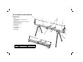
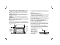
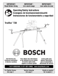
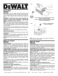
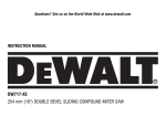
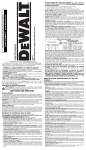
INSTRUCTION MANUAL
DWX723-XE
HEAVY-DUTY MITER SAW STAND
DWX724-XE
COMPACT MITER SAW STAND
DWX723-XE/DWX724-XE MITER SAW STANDS
Components List
FIG. 1
A. Beam
B. DW7231-XE Miter saw mounting brackets
C. Extension arm
D. DW7232-XE Work piece support and length stop
E. Extension arm end cap
F. Extension arm lock lever
G. Release levers
H. Carry handle
I. Locking locator clip
J. Leg lock lever
K. Release button
A
B
C
2
K
I
D
G
J
H
1
DWX723-XE
DWX724-XE
1
1765.3 mm (69.5")
1092.2 mm (43")
2
3835.4 mm (151")
2540 mm (100")
E
F
Tools Required
Definitions: Safety Guidelines
• Drill with 9.5 mm (3/8") drill bit (Not required for DEWALT Miter Saws)
• Crosshead #2 screwdriver
• 13 mm (1/2") Wrench
The definitions below describe the level of severity for each signal
word. Please read the manual and pay attention to these symbols.
DANGER: Indicates an imminently hazardous situation which, if
not avoided, will result in death or serious injury.
WARNING: Indicates a potentially hazardous situation which, if not
avoided, could result in death or serious injury.
CAUTION: Indicates a potentially hazardous situation which, if not
avoided, may result in minor or moderate injury.
NOTICE: indicates a practice not related to personal injury which, if
not avoided, may result in property damage.
Components (Fig. 1)
WARNING: Never modify the stand or any part of it. Damage or personal injury
could result.
Refer to Figure 1 for Components List.
GENERAL SAFETY INSTRUCTIONS FOR MITER SAW STANDS
WARNING: To reduce the risk of personal injury:
• ALWAYS use eye protection. All users and bystanders must wear eye protection
that conforms to AS/NZS1337.
• ALWAYS check the stability of the miter saw stand and the miter saw attached to
it before putting the stand or the saw into use.
• DO NOT mount any power tool other than a miter saw to this stand. Mounting
other power tools to this stand could result in severe personal injury.
• DO NOT exceed the weight this stand can hold. The main center beam of the
miter saw stand is designed to support 227 kg. (500 lbs.) safely in a work
environment. It is unsafe to climb, sit or stand on the stand.
• Follow the mounting instructions carefully. Fasten the miter saw to the saw
mounting brackets securely as instructed.
• DO NOT modify or use stand for operations for which it is unintended.
• DO NOT use the stand on uneven surfaces. The stand is designed to be used on
a flat, stable surface.
• DO NOT use on a slippery surface. The stand load capacity is greatly reduced
when used on slippery surfaces.
IF YOU HAVE ANY QUESTIONS OR COMMENTS ABOUT THIS OR ANY DEWALT TOOL,
CALL US AT: 1800 444 224 (Aust) or 0800 339 258 (NZ).
Miter Saw Stand with Folding Legs DWX723-XE/DWX724-XE
This stand is designed for use with most miter saws. If you have any problem with
alignment or mounting, call 1800 444 224 (Aust) or 0800 339 258 (NZ).
WARNING: For your own safety, read the miter saw instruction
manual before using any accessory. Failure to heed these
warnings may result in personal injury and serious damage to the
miter saw and the accessory. When servicing this tool, use only
identical replacement parts.
Carton Contents
1
2
2
1
Miter saw stand (DWX723-XE or DWX724-XE)
Miter saw mounting brackets (DW7231-XE)
Workpiece support and length stops (DW7232-XE)
Hardware bag
SAVE THESE INSTRUCTIONS
1
FIG. 2
Preparation (Fig. 2)
b. Adjust the height of the work support/stop (D) by loosening the knobs on both
sides (N) and raise or lower the top surface to align with a straight edge or level
to the saw table. Tighten the knobs.
NOTE: If the work support height adjustment slips down when under a load, the
weight limit of the work support has been exceeded. This weight limit is limited
by the tightness of the height adjustment knobs. Do not tighten more than finger
tight.
c. The work support/stop (D) can also be installed in the end cap (E) at the end of
the extension arms.
d. The length stop (O) may be rotated up to serve as a length stop or hold the end
of long workpieces.
J
1. Place the miter saw stand on the ground with the
folded legs facing up.
2. Depress the leg lock lever (J) or release button (K)
and pull leg up until the locking pin clicks into the
place. Repeat on each leg.
3. Lift the stand by the center beam and place it in an
upright position. The stand should be stable and
should not rock.
NOTE: Ensure all locking pins are engaged and the legs
are locked in place.
K
Adjustable Length Extension Arm (Fig. 5)
ASSEMBLY
To lengthen the support surface, turn the extension
arm lock lever counterclockwise to release the
extendable extension arm. Pull the extendable
extension arm out to the desired length. Turn the
extension arm lock lever clockwise to lock.
DW7232-XE Workpiece Support and Length Stops (Fig. 3–4)
a. The work support/stop (D) has a clamp
(L) to capture the beam and keep it
from being knocked off the beam by
your material. The knob (M) may be
locked by turning clockwise and the
work support/stop is free to be
repositioned when the knob is turned
counterclockwise. Do not overtighten,
firm pressure on the knob will hold the
stop in place.
FIG. 3
M
DW7231-XE DEWALT Miter Saw Mounting
Method (Fig. 6, 7)
D
L
WARNING: To reduce the risk of injury, turn unit off, disconnect machine
from power source before assembling the miter saw to the miter saw stand. An
accidental start-up can cause injury.
WARNING: Stability Hazard. You must use the Universal Miter Saw Mounting
Method when mounting a miter saw not manufactured by DEWALT to this miter saw
stand.
WARNING: To reduce the risk of personal injury, be sure the miter saw is fully
anchored on the stand.
WARNING: For your own safety, read and understand the miter saw instruction
manual before using. Failure to heed these warnings may result in personal injury and
serious damage to the miter saw and the accessory.
1. Place saw in operational position with blade facing you. Align with label on the
mounting bracket showing front.
2. Place a spacer, such as a 2 x 4, under one side of the miter saw to hold the
saw’s mounting feet above the work surface.
FIG. 4
D
N
O
FIG. 5
E
D
2
3. Hold a mounting bracket under the saw and feed a carriage bolt (hardware bag)
up through the bracket and the foot of the saw.
NOTE: See DW7231-XE Hardware Selection Chart for the correct mounting
hardware procedures for DEWALT miter saws. Follow all instructions properly,
otherwise the miter saw's table rotation may be obstructed.
4. Once the carriage bolt (hardware bag) is installed per DW7231-XE Hardware
Selection Chart, assemble a flat washer, lock washer and nut onto the bolt.
Tighten the bolts finger tight.
5. Repeat procedure on the other end of the bracket.
6. Move the 2 x 4 to the other side of the saw to hold the other end of the saw up in
order to access the saw base.
7. Feed carriage bolts through the other bracket and the base of the saw as before.
Ensure both brackets are parallel to each other.
8. To place the saw onto the stand, grasp and lift saw by mounting bracket
assembly by the release levers. These levers do not lock the saw laterally in
place but merely serve as a means of mounting the saw to the beam.
DW7231-XE HARDWARE SELECTION CHART
Left Side
Right Side
DW703-XE
1
1
DW705-XE
1
1
DW706-XE
1
1
DW708-XE
1
2
DW712-XE
1
2
DW713-XE
1
1
DW715-XE
1
1
DW716-XE
1
1
DW717-XE
2
1
DW718-XE
3
2
FIG. 6
1 = Long screw, Head on bottom
9. Approach the beam with saw/bracket assembly
FIG. 7
tilting toward your body slightly. Engage the concave
front lip of the mounting bracket with rounded edge
of beam. One of the brackets must engage the
locator clip (I) to prohibit lateral movement of the
saw during use.
I
10. When front edge of the beam and locking locator
clip are engaged, a slight downward pivot will allow secure engagement of the
release levers to the back of the beam. Rock the saw gently on the brackets to
verify locking in position.
11. Adjust the saw position as necessary to have the blade perpendicular to the
beam when in the 0 degree miter position.
12. Tighten the four nuts holding the saw to the brackets securely.
2 = Short screw, Head on bottom
3 = Long screw, Head on top
3
DW7231-XE Universal Miter Saw Mounting Method (Fig. 1, 7–9)
1. Once the Plywood size has been determined, drill 9.5 mm (3/8") holes 25.5 mm
(1") from the front corners of plywood, 355 mm (15") apart and 25.5 mm (1")
from the sides.
2. Place DW7231-XE mounting brackets on the stand:
a. Grasp and squeeze release levers (G).
b. Engage the concave front lip of the mounting bracket with rounded front edge
of beam. One of the mounting brackets must be engaged in the locator clip (I)
to prohibit lateral movement of the saw during use.
3. When the front edge of beam and locator clip are engaged, a slight downward
pivot will allow secure engagement of the release levers to the back of the beam.
Follow same procedure with second mounting bracket at the appropriate position
on the beam for the size of the plywood.
4. Place plywood onto mounting brackets and align drilled holes with slots in
mounting brackets. Refer to DW7231-XE Hardware Selection Chart and use
either Method 1 or 2 to secure plywood to mounting brackets.
5. Use 13 mm (1/2") wrench to tighten hardware.
6. The miter saw should be mounted to plywood using holes in the miter saw
base. The hardware size will be determined by the holes in the miter saw base.
Hardware should be 31.8 mm (1-1/4") longer than the maximum height of the
miter saw base at each mounting location.
a. Transfer location of mounting holes from miter saw base to plywood.
b. Drill holes accordingly to the size of the hardware chosen. NOTE: Hardware
must be purchased to mount miter saw to plywood. All purchased hardware
should be a minimum of Grade 5 or Class 8.8.
c. Secure miter saw to plywood
FIG. 9
as shown in Figure 9. Saw
base (P), 19 mm (3/4")
P
plywood (T), flat washer (Q),
lock washer (S) and nut (R).
NOTE: Ensure a flat washer
(Q) is used between plywood
(T)and lock washer (S).
T
d. Tighten all hardware.
Q
WARNING: To reduce the risk of injury, turn unit off, disconnect machine
from power source before assembling the miter saw to the miter saw stand. An
accidental start-up can cause injury.
WARNING: Stability Hazard. You must use the plywood mounting method
described in the following instructions when mounting a miter saw not manufactured
by DeWalt to this miter saw stand.
WARNING: To reduce the risk of personal injury, be sure the miter saw is fully
anchored on the stand.
WARNING: For your own safety, read and understand the miter saw instruction
manual before using. Failure to heed these warnings may result in personal injury and
serious damage to the miter saw and the accessory.
NOTE: If you do not have a DEWALT miter saw, you must use 19 mm (3/4") plywood
to mount your miter saw.
The plywood must be a minimum of 101.6 mm (4") wider than the largest width of
the miter saw base. The plywood should be at least as deep as the smallest depth
of the miter saw base or a minimum of 406.4 mm (16") if miter saw base is smaller.
Ensure the plywood is square.
FIG. 8
WIDTH OF SAW + 101.6 mm (4")
25.5 mm (1")
MINIMUM OF
406.4 mm
(16") MUST BE
AT LEAST AS
DEEP AS THE
SAW BEING
MOUNTING
381 mm
(15")
BOTH
SIDES
25.5 mm (1")
25.5 mm (1")
MOUNT MITER SAW IN
SHADED AREA
9.5 mm (3/8")
DIAMETER
HOLES, ALL 4
CORNERS
50.8 mm (2")
MINIMUM BOTH
SIDES
25.5 mm (1")
S
4
R
Carry Strap
Recommended accessories for use with your tool are available at extra cost from
your local service center. If you need any assistance in locating any accessory, please
contact Stanley Black & Decker, 82 Taryn Drive, Epping, VIC 3076 Australia or call
1800 444 224 or (NZ). 0800 339 258.
If you purchase the carry strap accessory for DEWALT stands, use the square hole in
the metal end to mount the accessory.
Locking Locator Clip (Fig. 1, 7)
The locking locator clip (I) keeps the saw from sliding left or right during cutting
operations. To move the clip, remove saw/bracket assembly, loosen the screw in the
center of the clip, slide it to the desired position and tighten the screw. You can then
remount the saw/bracket in the new location.
Removing the Saw
Once the miter saw is fastened to the brackets, it can be removed by grasping the
release levers, pulling up slightly to clear the beam and can be set down on the non
marring feet for transportation or cleaning.
Carry Handle (Fig. 10)
A handle has been supplied to transport the miter saw
stand to and from the work site.
WARNING: To reduce the risk of personal injury, DO
NOT attempt to store or carry the stand with the saw
attached. Loss of control may result.
FIG. 10
MAINTENANCE
Repairs
To assure product SAFETY and RELIABILITY, repairs, maintenance and adjustment
(including brush inspection and replacement) should be performed by certified
service centers or other qualified service organizations, always using identical
replacement parts.
ACCESSORIES
WARNING: Since accessories, other than those offered by DEWALT, have not been
tested with this product, use of such accessories with this tool could be hazardous.
To reduce the risk of injury, do not create unstable conditions and use only with
DEWALT miter saw stands.
5
Stanley Black & Decker
82 Taryn Drive, Epping, VIC 3076 Australia • 1800 444 224 (Aust) or 0800 339 258 (NZ)
www.dewalt.com.au • www.dewalt.com.nz
(NOV11)
Part No. N150464
DWX723-XE, DWX724-XE
Copyright © 2011 DEWALT
The following are trademarks for one or more DEWALT power tools: the yellow and black color scheme; the “D” shaped air intake grill; the array of pyramids on the handgrip;
the kit box configuration; and the array of lozenge-shaped humps on the surface of the tool.