1
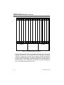
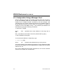
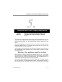
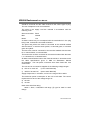
KBU64 Rackmount User Manual Fivemere Ltd. Cabletron Systems Ltd. Fivemere House Network House 161 High Street Newbury Business Park Aldershot London Road, Newbury Hampshire, England Berkshire, England GU11 1TT RG13 2PZ Telephone: [44] (0)1635 580000 Fax: [44] (0)1635 44578 KBU64 Rackmount User Manual Publication — 80-10100001-09 Publication Notice: This manual has been compiled and checked for accuracy. However the information contained in this manual does not constitute a warranty of performance. Cabletron Systems Ltd. reserves the right to revise this publication from time to time without notice. Cabletron Systems Ltd. assumes no liability for losses incurred as a result of out of date or incorrect information contained in this manual. Proprietary Notice: © 1991-1997, Cabletron Systems Ltd., all rights reserved. This document may not in whole or part be copied, photocopied, reproduced, translated, or reduced to any electronic medium or machine-readable form without prior consent from Cabletron Systems Ltd. Approval Notice: This equipment is approved for connection to all United Kingdom telecommunications services, including British Telecom PLC, Hull City Council and Mercury Communications, and is subject to the conditions set out in these instructions for use. All users of this equipment in the UK, Europe and USA must make themselves familiar with the statutory instructions contained in Section 7. Pan European Approval: Where the Pan European Approval CE Mark ‘168X’ is applied to the product; this approval is for connection of the ISDN and X.21 interfaces within the European Community (EC). Where an EC country requires approval for connection of the V35 or V24 Link ports to a PTO’s Digital Leased Circuit (DLC), this approval is necessary in that country before connection to the DLC can be permitted. Approval in non EC countries is subject to local regulations in force, please contact your Technical Support for information. EMC Directive: This product has been designed for use in Commercial and Light Industrial environments and tested to relevant EMC Standards as listed in the European O.J. All testing was carried out using screened interconnection cables. Should the equipment be used in a different environment the user may need to take additional EMC precautions. Acknowledgements: Kilostream™ is a trademark of British Telecom PLC. Fivemere Ltd. is a subsidiary of Cabletron Systems Inc., USA. ii 80-10100001-09 KBU64 Rackmount User Manual History Sheet 80-10100001-09 80-10100001-09 Issued separately for the R/M due to USA requirements 21 January 1998 iii KBU64 Rackmount User Manual TABLE OF CONTENTS 1 KBU 64 RACKMOUNT SPECIFICATION 1–1 1.1 INTRODUCTION 1–1 2 FRONT AND REAR PANELS AND INTERFACES 2–1 2.1 FRONT PANEL 2.2 REAR INTERFACE CARDS 2.2.1 LINK SETTINGS 2.2.2 COMMAND PORT - KBU 64 REAR INTERFACE CARDS 2.2.3 V35 REAR INTERFACE CARD 2.2.4 X21 REAR INTERFACE CARD 2.2.5 V24 REAR INTERFACE CARD 2–1 2–1 2–3 2–4 2–5 2–6 2–6 3 MANAGER CARD 3–1 3.1 INTRODUCTION 3.2 FRONT PANEL 3.3 REAR PANEL 3–1 3–3 3–3 4 CARD INSTALLATION 4–1 4.1 MANAGER CARD INSTALLATION 4.2 CONFIGURATION USING A MANAGER CARD 4–1 4–2 5 INSTALLATION AND POWER SUPPLY REQUIREMENTS 5–1 6 RACK SPECIFICATIONS 6–1 7 REGULATORY REQUIREMENTS 7–1 7.1 UNITED KINGDOM AND EUROPE 7.2 ADDITIONAL UK REQUIREMENTS 7–1 7–1 iv 80-10100001-09 KBU 64 Rackmount Specification 1 KBU 64 Rackmount Specification 1.1 Introduction This manual describes the Rackmount version of the KBU64. The standalone KBU 64 has its own manual, Publication 80-10100000. For information on the command menus and parameters in the rackmount version, you will need to refer to the standalone KBU 64 manual. The rackmount KBU 64 is a dual channel rack mountable card that uses the KBU 64 Card Frame as a host for power and management via the Management Card. The rackmounted KBU 64 consists of a KBU card and a rear interface card (card 'pair'), both cards connecting to a motherplane for power source and management. Rear interface cards may be ordered as X.21, V.24, or V.35 variants. Power supply is via two switching supplies, which normally load share when both are fitted. 80-10100001-09 1–1 KBU64 Rackmount User Manual Fivemere Fivemere Figure 1.1 The KBU 64 Rackmount Version Up to 13 KBU 64 card pairs may be fitted with either one or two power supplies for resilience. The 1st card slot is for the Manager Card which controls all cards within the rack via the KBU 64 polled management system. If the Manager Card is not fitted, management of each card can be performed by connecting a terminal directly to the command port of the rear interface card. When fitted, the manager card must be placed in slot 1, the left-hand most slot of the rack. 1–2 80-10100001-09 KBU 64 Rackmount Specification The rackmount version of the KBU 64 is functionally the same as the standalone in most respects, as it uses the same software. Therefore most of the sections of your KBU64 Manual manual (Publication 8010100000) relating to KBU 64's operation are relevant. The rackmount card functionality differs in the following ways:• There is a single 15 way command port on each KBU 64 rear card for all commands and alarms. There is no separate alarm port or alarm relay output on the cards. The command port has the same function as the standalone 25 way command port. • The Management Card (if fitted) provides a command port for access to all KBU 64 cards in the rack. • Standard physical interfaces are provided for X21 (15 way 'D'), V35 (34 way MRAC), and V24 (25 way 'D'). This means that the V11/V28 selection links are not provided as they are no longer necessary. A choice of 3 rear interface cards exist to provide these interfaces. • The interface LED's are as for the standalone except that the Link LED's have been omitted for front panel clarity. • The ISDN cable is connected to the Rear Interface Card by an RJ 45 style plug. • Power indication for each power supply is present on the Manager Card. 80-10100001-09 1–3 Front and Rear Panels and Interfaces 2 Front and Rear Panels and Interfaces 2.1 Front Panel See the KBU64 standalone manual (Publication 80-10100000) for the description of operation. 2.2 Rear Interface Cards With all 3 card types the USER ports are configured as physical DCEs, the LINK ports as DTEs. The USER ports are female and the LINK are male for X21 and V24, both USER and LINK ports are female for V35. All three card types use standard pin connection and so require 1 to 1 cables for connection to both user equipment and link equipment. 80-10100001-09 2–1 KBU64 Rackmount User Manual US E R 1 T R C I S USER 1 USER 1 USER 1 L IN K 1 L IN K 1 L IN K 1 USER 2 USER 2 USER 2 L IN K 2 L IN K 2 L IN K 2 COMMAND COMMAND COMMAND 10 3 10 4 10 8 10 7 11 4 11 5 10 5 10 9 B AC K U P US E R 2 T R C I S 10 3 10 4 10 8 10 7 11 4 11 5 10 5 10 9 B AC K U P B1 B1 B2 B2 IN U S E B AC K UP IN U S E B AC K UP AL AR M 1 AL AR M 2 IS D N F ron t Rear ( X .2 1 ) IS D N Rear ( V .2 4 ) IS D N Rear ( V .3 5 ) Figure 2.1 Front and rear Panel Layout 2–2 80-10100001-09 Front and Rear Panels and Interfaces 2.2.1 Link Settings For all 3 types of Rear Interface Card the command port jumper settings are as follows: With Manager Card Without Manager Card Link Normal Polled Polled Only JP8 IN IN X JP9 OUT OUT X JP10 OUT IN X JP11 IN OUT X JP12 IN IN OUT JP13 IN IN OUT JP14 IN IN OUT 'X' = don't care 80-10100001-09 2–3 KBU64 Rackmount User Manual 2.2.2 Command Port - KBU 64 Rear Interface Cards The command port on each of the Rear Interface Card types is a female 15 way 'D' type and uses the same V28 level circuits as the standalone KBU 64. You can only use this command port when a Manager Card is not fitted into the rack (please see section 3). The pin assignments are as follows: Pin No. 1 2 3 4 5 8 10 12 15 Circuit No. 101 103 108 104 107 102 105 109 106 Signal Name Chassis Earth Transmit Data Data Terminal Ready Receive Data Data Set Ready Signal Ground/Chassis Earth Request to Send Data Carrier Detect Clear to Send A standard cable (CAB0032) can be supplied to present a standard 25 way interface to the command terminal or PC. This cable has male connectors at both ends. 2–4 80-10100001-09 Front and Rear Panels and Interfaces 2.2.3 V35 Rear Interface Card The User and Link connectors are both 34 way female MRAC. The pin assignments are as follows: Pin No. A B Circuit No. 101 102 P S R T C D E H F Y AA V X 103A 103B 104A 104B 105 106 107 108 109 114A 114B 115A 115B 80-10100001-09 Signal Name Chassis Earth Signal Ground/Chassis Earth Transmit Data A Transmit Data B Receive Data A Receive Data B Request to Send Clear to Send Data Set Ready Data Terminal Ready Data Carrier Detect Transmit Clock A Transmit Clock B Receive Clock A Receive Clock B Assuming configured as DTE Common return Common return Generator Generator Load Load Generator Load Load Generator Load Load Load Load Load 2–5 KBU64 Rackmount User Manual 2.2.4 X21 Rear Interface Card The User and Link connectors are both 15 way 'D'. The pin assignments are as follows: Pin No. 1 8 2 9 3 10 4 11 5 12 6 13 Circuit No. Ground G Ta Tb Ca Cb Ra Rb Ia Ib Sa Sb Signal Name Chassis Earth Signal Ground/Chassis Earth Transmit Data A Transmit Data B Control A Control B Receive Data A Receive Data B Indicate A Indicate B Signal Timing A Signal Timing B Assuming configured as DTE Common return Common return Generator Generator Generator Generator Load Load Load Load Load Load 2.2.5 V24 Rear Interface Card The User and Link connectors are both 25 way 'D'. The pin assignments are as follows: Pin No. 1 2 3 4 5 6 7 8 15 17 20 2–6 Circuit No. 101 103 104 105 106 107 102 109 114 115 108 Signal Name Chassis Earth Transmit Data Receive Data Request to Send Clear to Send Data Set Ready Signal Ground/Chassis Earth Data Carrier Detect Transmit Clock Receive Clock Data Terminal Ready Assuming configured as DTE Common return Generator Load Generator Load Load Common return Load Load Load Generator 80-10100001-09 Manager Card 3 Manager Card 3.1 Introduction The KBU 64 Manager Card is a discrete card for use with only rackmount KBU 64 cards. Like the rackmount KBU 64, the Manager Card also consists of a card pair. The rear card provides a command port for management of all KBU 64 cards within its rack. The Manager Card must always be fitted in slot 1, the slot on the left when viewing the rack from the front. Important When the manager Card is used you cannot use the command port of any KBU 64 Rear Interface Card. With the Manager Card fitted you must remove links 12, 13 and 14 on every KBU 64 Rear Interface Card to disconnect the card command interface. If you do not do this the signal flow to the Manager Card will be corrupted. 80-10100001-09 3–1 KBU64 Rackmount User Manual RX D TX D 1 OF F 2 OF F 3 OF F 4 OF F 5 OF F 6 OF F 7 OF F 8 OF F 9 OF F 10 OF F 11 OF F 12 OF F 13 OF F COM M AN D PW R 1 PW R 2 F ro n t Rear Figure 3.1 Front and Rear Panels of the Manager Card 3–2 80-10100001-09 Manager Card 3.2 Front Panel The front panel of the Manager Card has the following controls and indicators: • Transmit and receive data LED’s for the command terminal data lines. These LED’s display data activity on both the transmit and receive data circuits. • AC power indication for each of the power supplies. These LED’s are fed from the AC power sensing circuits from each power supply. • A lock out switch for each of the 13 channels. These are provided to enable the user to set the poll number for individual KBU 64 cards. Once the cards have been programmed ALL the lockout switches must be set to enable the KBU 64s. The lockout switches can also be used to isolate a KBU card that is streaming unwanted alarms, so allowing other KBU cards to have access from the Manager Card. • An LED for each channel to indicate which channel is actively selected and in communication with the Manager Card. When another KBU 64 card is polled that card's LED will light and the previously selected card LED will extinguish. 3.3 Rear Panel The command port on Manager Rear Interface Card is a female 25 way 'D' type and uses the same V28 level circuits and pin connections as the standalone KBU 64. 80-10100001-09 3–3 KBU64 Rackmount User Manual The pin assignments are as follows: Pin No. 1 2 3 4 5 6 7 8 15 17 20 Circuit No. 101 103 104 105 106 107 102 109 114 115 108 Signal Name Chassis Earth Transmit Data Receive Data Request to Send Clear to Send Data Set Ready Signal Ground/Chassis Earth Data Carrier Detect Transmit clock Receive clock Data Terminal Ready These command ports are PSV4/1 compatible and can therefore be connected to external port sharing devices (PSV’s) for management of multiple racks of KBU 64s in the same way as the standalone version. 3–4 80-10100001-09 Card Installation 4 Card Installation Each KBU 64 ‘front’ card must be associated with an appropriate (V.24, X.21, or V.35) rear interface card i.e. they should always be installed in pairs (although no damage will result in partial installation) If the KBU 64s are to be managed individually via their rear panel command port and there is no manager card present then, after connection of the user, link, and command cables, the KBU 64s can be treated in the same manner as standalone KBU 64s for configuration purposes. When installing KBU cards in a rack make sure to configure the Rear Interface Card straps correctly, depending on whether a Manager Card is fitted. Refer to KBU64 Manual (Publication 80-10100000) - Link Settings. 4.1 Manager Card Installation When the KBU 64s are to be managed with a KBU 64 rack manager card then the manager card must be placed in slot 1, the slot on the far left when viewing the rack from the front. If the Manager command port is conected direct to a terminal/PC then cable CAB0017 or CAB0018 is required (CAB0017 has a female connector and CAB0018 a male connector at the terminal end). If connected to a PSV port sharer please contact your Technical Support for details. With a directly connected terminal it may be necessary to force CTS or DCD to the terminal, depending on the terminal’s requirements. 80-10100001-09 4–1 KBU64 Rackmount User Manual 4.2 Configuration Using a Manager Card With the Manager Card pair and all KBU card pairs fitted the first task is to set the individual KBU 64 poll numbers. Once all the units are installed and a suitable terminal connected to the rack manager card command port, the lockout switches should be set to disable access to all the KBU 64s except one (for the sake of convenience it is better to configure the left most KBU 64 first). The individual poll address can then be set by typing the following commands:1> SET POLL xxx[CR] where 999 xxx represents the unique address in the range 001 to Next, the KBU 64 card needs to be set for polled mode by typing 1> SET CONSOLE POLL[CR] To check that the KBU 64 is responding, type 1> POLL xxx [CR] where xxx represents the address that you have just set The lockout switch for this KBU 64 should then be set to disable the KBU 64 and the next KBU 64 can be programmed by enabling via the lockout switches etc. etc. Once all the KBU 64s have been programmed, the lockout switches must be set to enable ALL the KBU 64s. 4–2 80-10100001-09 Installation and Power Supply Requirements 5 Installation and Power Supply Requirements Safety Warning: Before connecting the mains supply to the unit check the supply voltage as detailed below. The product is a high density rack mounted unit designed to sit in a 19" communications cabinet, it has four fixing points, two down each side of the front of the frame. All four fixing points must be securely fix the frame. The unit is supplied with a metal front cover in order to comply with the European EMC Directive. To comply with the Directive this cover must be fitted while the unit is operating. On the rear of the unit there are two IEC mains sockets for connection to two independent mains supplies. The primary earth connection is made via these sockets. Warning - this appliance must be earthed. Mains cables, 2 metres in length are supplied with the unit. This should be connected to a suitable mains supply. The mains plug is the primary disconnect device for the unit. Ensure that the unit is installed near to a socket outlet and that the outlet is easily accessible. The mains cables supplied with the unit is fitted with a moulded 13 amp plug for connection to a standard socket outlet. Should the plug not be of the correct type for the outlets that it is to be connected to, the plug 80-10100001-09 5–1 KBU64 Rackmount User Manual should be removed and the cable re-wired to the correct type of plug. The use of adaptors is not recommended. The wires in the supply cord are coloured in accordance with the following code:Green and Yellow Earth Blue Neutral Brown Live As these colours may not correspond with the termination's in the plug being used, it should be connected as follows:The green and yellow wire must be connected to the terminal marked with the letter E, or with the earth symbol, or coloured green, or coloured green and yellow. The blue wire must be connected to the terminal marked with the letter N, or coloured black, or coloured blue. The brown wire must be connected to the terminal marked with the letter L, or coloured red, or coloured brown. All data communications links to the frame should be in accordance with the cable specifications given in KBU 64 Standalone Manual 80-10100000. The rear panel connectors have been fitted with 4-40 screw-locks. The unit can be connected to supplies of the following voltage ranges:a) 97V AC to 132V AC (110 to 120V Nominal) c) 195V AC to 264V AC (220 to 240V Nominal) Supply frequencies, in all cases, can be in the range 47Hz to 63Hz. The maximum power consumption of the unit is 125 watts. The current requirement for each of the voltage ranges is:a) 2A max. b) 1A max. Ideal mains inlet fuse rating: 20mm x 5mm, 1.6AH,250V Anti-surge (T) type for 220V to 240V ratings. 5–2 80-10100001-09 Installation and Power Supply Requirements 20mm x 5mm, 3.15AH,250V Anti-surge (T) type for 110V to 120V ratings. If any problems are encountered with fuses continually blowing the following alternative ratings maybe used: 20mm x 5mm, 3.15AH,250V Anti-surge (T) type for 220V to 240V ratings. 20mm x 5mm, 6.3AH,250V Anti-surge (T) type for 110V to 120V ratings. Caution — for continued protection against risk of fire, replace only with same type and rating of fuse. NOTE: The rack should be professionally installed by a competent engineer. There are no operator serviceable parts inside the unit and it should only be opened by a qualified service engineer. The mains supply should be disconnected before removing the cover. 80-10100001-09 5–3 Rack Specifications 6 Rack Specifications Dimensions 482mm W; 400mm H (9U); 370mm D Mains Voltage 93-132V (110-120V nominal) 187-264V (220-240V nominal) Consumption 200VA max. Frequency 50/60Hz nominal Mains Rear Panel Fuses 1.6 or 3.15AH, 250V Anti-Surge (T) 20x5mm (220-240V range) 3.15 or 6.3AH, 250V Anti-Surge (T) 20x5mm (110-120V range) 80-10100001-09 6–1 KBU64 Rackmount User Manual Environment Ambient temperature: Operating 0°C to 30°C Storage -20°C to 70°C Atmospheric pressure: 86.0kPa to 106.0kPa Relative Humidity: non-condensing 6–2 5% to 95% 80-10100001-09 Regulatory Requirements 7 Regulatory Requirements 7.1 United Kingdom and Europe Users based in the United Kingdom and Europe must pay particular attention to the information contained in sections 7.1 and 7.2. B.A.B.T. Pan European Approval number AA6046512. 1. The KBU 64 Rackmount is approved for connection to ISDN and X.21 leased circuit services provided by a European Public Telecommunications Operator. 2. Only connect apparatus complying with the requirements of SELV in accordance with clause 2.3 of EN 60 950 to the ports on the rear panel of your unit marked User 1, User 2, Link 1, Link 2, Command and Alarm. 3. Only connect apparatus complying with the requirements of TNV in accordance with clause 6.2 of EN 60 950 to the port on the rear panel of your unit marked ISDN ‘S’. 7.2 Additional UK Requirements 1. All apparatus connected to the user ports and thereby connected directly or indirectly to the British Telecom circuits must be approved apparatus as defined in Section 22 of the British Telecommunications Act 1984. 2. The interconnection cables detailed in the KBU64 Manual (Publication 8010100000) form part of the approval and cabling itself constitute a relevant branch system for the digital circuits detailed below. 80-10100001-09 7–1 KBU64 Rackmount User Manual 3. The KBU 64 Rackmount is approved for direct connection to the X.21 and X.21 bis (V.35) or X.21 bis (V.28) Kilostream provided by British Telecom PLC or any similar service provided by other British Telecommunications operators, or a relevant branch system for those digital circuits which accord to CCITT recommendations X.21 and X.21 bis. Where connection is made to circuits conforming to CCITT, X21 bis, Service Categories 1 and 2 are supported. For Service Category 1, data rates of 2.4 kbit/s to 19.2 kbit/s are available and connection is via an integral cable terminated with a 25 way D-Type connector conforming to BS 6623: Part 1: 1985. For Service Category 2, data rates of 48k, 56k and 64kbit/s may be used. Connection is via an integral cable terminated with a 34 pin connector conforming to BS 6623: Part 1: 1986. 4. If any other apparatus, including cabling or wiring is to be connected between the apparatus, and the point of connection to the digital circuits detailed in above, then all that other apparatus shall conform to the following: a) The overall transmission characteristics of all that other apparatus shall be such as to introduce no material effect upon the electrical conditions presented to one another by the apparatus and the digital circuit. b) All the other apparatus shall comprise only: i) apparatus approved (see note) for the purpose of connection between the apparatus and the digital circuit, and; ii) cable or wiring complying with a code of practice for the installation of apparatus covered by this standard or such other requirements as may be applicable. Note: Such apparatus may have been approved subject to limitations on its use. 7–2 80-10100001-09