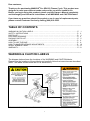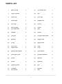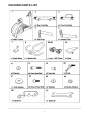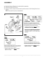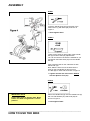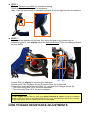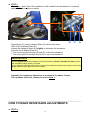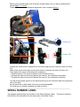
1
MAXXUS ® PRO SPK-23 FITNESS CYCLE OWNER’S MANUAL Dear customer, Thank you for purchasing MAXXUS® Pro SPK-23 Fitness Cycle. This product was designed to meet your workout needs and provide you with a healthier life. Before you begin using this product, please read the Owner’s Manual completely and thoroughly and follow the instructions of all WARNING and CAUTION labels. If you have any questions about this product or are in need of replacement parts, please contact Customer Service by calling (909) 212-5555. ____________________________________________________________ TABLE OF CONTENTS WARNING & CAUTION LABELS…..…………………….……….…………………………….….....P. SAFETY INSTRUCTIONS.………………………………….…………………………………………P. PARTS LIST…………….………………………………………………………………………………..P. EXPLODED DRAWING…..…………………………………………………………………………….P. PACKING PARTS LIST…………………...…………..…………………………………….………….P. ASSEMBLY.………………………………………....……………………………………….….……….P. HOW TO USE THE BIKE……………………….…………..……..…………...……………….……..P. HOW TO MAKE RESISTANCE ADJUSTMENTS………….…………………..……………………P. SERIAL NUMBER LABEL….…………..………..……….………………………….……………...…P. WARRANTY..……………………..……………..………….……………………………………………P. 1 2 3 4 5 6 9 10 13 13 ____________________________________________________________ WARNING & CAUTION LABELS The diagram below shows the locations of the WARNING and CAUTION labels. Please note the locations of these labels and carefully follow the instructions as described. (Note: The labels shown below are not of actual size.) ____________________________________________________________ 1 SAFETY INSTRUCTIONS Before you start to assemble and operate this product, please carefully read the Owner’s Manual in its entirety. Please follow all instructions in this Owner’s Manual as described. Be sure to read through the Safety Instructions below and keep this Owner’s Manual for future reference. ● Misuse of this product may cause serious injury. ● Consult your physician before starting any exercise program. Please follow your physician’s advice on fitness training. ● Please follow all warnings, cautions, and instructions carefully while using this product. ● Only use original parts (except personal saddle) accompanying this product. ● This product is designed for adult use only. Do not allow children to use this product or be around this product when in use. ● The maximum user's weight is 265lbs / 120kgs. ● Place this product on an even, non-slippery surface. Keep this product away from dust. Avoid placing and using this product in a damp environment. Please wear appropriate sports clothing while exercising. Do not wear loose clothes that could become caught on the bike. Please wear appropriate sports shoes for foot protection. ● To stop, reduce your pedal speed and switch the tension lever to gear 8. It is not recommended to stop by discontinuing pedaling motion as that can cause serious injury. ● Set tension lever to maximum level (gear 8) when this product is not in use. ● This product is not intended for therapeutic use. ● Inspect product components every 1~2 months to ensure levers and connections are snug and tight for safe operation. Replace any worn parts immediately. ____________________________________________________________ 2 PARTS LIST Item 1 2 3 4 5 6 7 8 9 10 11 12 13 14 15 16 17 18 19 20 21 22 23 24 25 26 27 28 29 30 31 32 33 34 35 36 Description Main Frame Rear Foot Bar Front Foot Bar U-Zone Bar Seat Post Handle Post Seat Slider Handle Bar End Cap Adjustable Pad Move Wheel Hex Head Bolt Nylon Nut Washer Hex Head Bolt Cap Nut End Cap Bearing Bearing S Nut Belt Wheel Rod Left Cover Right Cover Spring Elbow Pad Support Rear Cover Front Left Cover Front Right Cover Screw Screw Screw Screw Tapping Screw Tapping Screw Flywheel Belt Wheel Quantity 1 1 1 1 1 1 1 1 2 2 2 2 2 4 4 2 2 2 2 1 1 1 1 1 2 1 1 1 1 2 2 2 2 2 1 1 Item 37 38 39 40 41 42 43 44 45 46 47 48 49 50 51 52 53 54 55 56 57 58 59 60 61 62 63 64 65 66 67 68 69 70 71 72 Description Fly Wheel Rod Spring Washer Nut Adjustable Bolt Lock Nut Brake Pad Stopper Set Tension Lever Screw Inner Chain Cover Screw Belt Belt Deck Screw Outer Chain Cover Round Head Screw Left Crank Right Crank Left Pedal Right Pedal Bolt Cap Plug Knob Flat Washer Seat Round Head Bolt End Cap Washer Spanner Spanner Spring Washer Nut Elbow Pad Bracket Bolt Quantity 1 2 2 2 2 2 1 1 2 1 2 1 1 4 1 10 1 1 1 1 2 2 2 4 2 1 2 1 2 1 1 2 2 2 1 1 ____________________________________________________________ 3 EXPLODED DRAWING ____________________________________________________________ 4 PACKING PARTS LIST ____________________________________________________________ 5 ASSEMBLY ● Read the Owner’s Manual in its entirety before assembly. ● Remove all parts from the box. ● Check to confirm receipt of all parts and quantities shown in the Packing Parts List on page 5. (Note: Some parts may be pre-assembled.) STEP 2 Slide the Front Foot Bar (3) to the front of the Main Frame (1) adding two Washers (14), two Spring Washers (68), two Cap Nuts (16), and two Hex Head Bolts (15) as shown in Figure 1. ** Tighten all bolts used in STEP 2 with the two Spanner Tools (66) & (67). ** You can use the Styrofoam (inner packing material) as a support to keep the Front Foot Bar (3) higher for easier tightening of the bolts. STEP 3 STEP 1 Insert the U-Zone Bar (4) into the holes of the Front Foot Bar (3) adding two Washers (65) and two Round Head Bolts (63) as shown in Figure 1. Slide the Rear Foot Bar (2) to the rear of the Main Frame (1) adding two Washers (14) and two Hex Head Bolts (15) as shown in Figure 1. ** Tighten all bolts used in STEP 3 with the Spanner Tool (66). ** Tighten all bolts used in STEP 1 with the Spanner Tool (66). ____________________________________________________________ 6 ASSEMBLY STEP 4 Attach the Left Pedal (55) and Right Pedal (56) to the Left Crank (53) and Right Crank (54) as shown in Figure 2. ** Tighten the Left & Right Pedals used in STEP 4 with the Spanner Tool (67). STEP 5 Insert the Seat Post (5) into the tube of the Main Frame (1) with Knob (60) as shown in Figure 3. ** Hand tighten ONLY. STEP 6 Affix the Seat (62) on the bar of the Seat Slider (7). Next, slide this set onto the Seat Post (5) with Flat Washer (61) and Knob (60) and then tighten as shown in Figure 3. ** Hand tighten ONLY. ____________________________ ________________________________ ASSEMBLY STEP 7 Insert the Handle Post (6) into the tube of the Main Frame (1) with Knob (60) as shown in Figure 4. ** Hand tighten ONLY. STEP 8 There are two holes on either side of the Handle Bar (8) for Elbow Pad (70) adjustments. You can choose the hole which is suitable for you and tighten the Elbow Pad (70) onto the Handle Bar (8). First, insert the bolts on the underside of each Elbow Pad (70). Next, slide the other end of the bolts into the holes on the Handle Bar (8) and screw on one Nut (69) on each side as shown in Figure 4. ** Tighten all bolts and nuts used in STEP 8 with the Spanner Tool (67). STEP 9 IMPORTANT NOTE Please make sure all Screws, Nuts, Bolts, Pedals and Seat are tightened in correct position. Attach the Handle Bar (8) onto the Handle Post (6) with one Flat Washer (61) and Knob (60) as shown in Figure 4. ** Hand tighten ONLY. ____________________________________________________________ HOW TO USE THE BIKE After assembling the bike and tightening all appropriate components as instructed, you can now begin using bike. Handle bar, seat, and elbow pad adjustments allow you to adjust the bike to fit your size and body frame. Seat with spring on the underside brings you comfort while riding. Streamline surface design of this bike fits in with ergonomics and increases comfort. ● HANDLEBAR ADJUSTMENT (1) Forward / Backward: Loosen the knob (60) on the handle post (6), slide the handle bar (8) forward or backward and tighten the knob (60) to lock the handle bar (8) into position. (2) Up / Down: Loosen the knob (60) on the main frame (1), slide the handle post (6) up or down and tighten the knob (60) to lock the handle bar (8) into position. ● SEAT ADJUSTMENT (1) Forward / Backward: Loosen the knob (60) on the seat post (5), slide the seat slider (7) forward or backward and tighten the knob (60) to lock the seat (62) into position. (2) Up / Down: Loosen the knob (60) on the main frame (1), slide the seat post (5) up or down and tighten the knob (60) to lock the seat (62) into position. ● SEAT REPLACEMENT The included seat (62) meets the standard specifications for this bike and can easily be adjusted and removed. This seat is interchangeable with your own seat for added personal comfort. ● ELBOW PAD ADJUSTMENT The movable elbow pad (70) design offers users different options for adjustable elbow positioning. There are two holes on either side of the handle bar (8) for elbow pad (70) adjustments. You can choose the hole which is suitable for your body type and tighten the elbow pad (70) onto the handle bar (8). ● TENSION LEVER ADJUSTMENT This bike allows you to burn more calories at the lower tension levels. The different levels provide you with options to extend your workout and increase muscle tone. The 1 to 8 range of tension levels offer options for users to train their body gradually. Gear 1 is the lowest tension level; Gear 8 is the highest tension level (brake). Slide the tension lever (44) for tension level setting. ● WATER BOTTLE & WATER BOTTLE HOLDER The water bottle holder can be mounted anywhere of the handle bar (8). You can install the water bottle holder at your discretion for added convenience. ● STOP / BRAKE If you want to stop, reduce your pedal speed and switch the tension lever to gear 8. It’s not recommended to stop by discontinuing pedaling motion as that can cause serious injury. ● WHEN BIKE IS NOT IN USE When the bike is not in use, set the tension lever to maximum level (gear 8) to prevent the flywheel from moving. ____________________________________________________________ HOW TO MAKE RESISTANCE ADJUSTMENTS STEP 1 Slide the Tension Lever (#44) for resistance setting. There are 8 gears (1 through 8) of resistance. Gear 1 has the lowest level of resistance and gear 8 has the highest level of resistance. STEP 2 If you want the resistance to be less, then move the gear to the lowest level of resistance (gear 8), and slightly adjust the Shift Lever Wire (Pillar and Hexagon Screw) as seen below. (A) (B) Loosen Pillar (A) slightly to increase the resistance. Double check if the Hexagon Screw (B) beside Pillar (A) is tightened. If it becomes loose while adjusting Pillar (A), re-tighten the Hexagon Screw (B). ** The more loose Pillar (A) is, the more resistance. ** The more tight Pillar (A) is, the less resistance. IMPORTANT NOTE Please slightly adjust Pillar (A) each time (about 2 threads at a time) to find the resistance which meets your need. If you adjust Pillar (A) too much, the resistance will become greater at the lower gears and the higher gears will not be usable. ____________________________________________________________ HOW TO MAKE RESISTANCE ADJUSTMENTS 11 STEP 3 After Steps 1 and 2 and if the resistance is still needed to be decreased or increased, please follow the instruction below. (E) (C) (D) Press Spring (C), then U-shaped Plate (D) will become loose. Take off the U-shaped Plate (D). Loosen the Hexagon Screw (E) slightly to decrease the resistance. Put back the U-shaped Plate (D). ** The more loose the Hexagon Screw (E) is, the less resistance. ** The more tight the Hexagon Screw (E) is, the more resistance. IMPORTANT NOTE Please slightly adjust the Hexagon Screw (E) each time (about 2 threads at a time) to find the resistance which meets your need. If you adjust the Hexagon Screw (E) too much, the resistance will become greater at the lower gears and the higher gears will not be usable. Normally, the resistance adjustment is resolved in the above 3 steps. If the problem still exists, please proceed to Step 4. ____________________________________________________________ HOW TO MAKE RESISTANCE ADJUSTMENTS STEP 4 12 Before you proceed further with this step, please make sure you have completed the above Steps 1, 2, and 3. If bike still needs more resistance adjustment, then complete Step 4. Picture (F) Picture (G) Loosen the screw which is tightened on the black cap (as seen circled in blue in Picture (F)). Take off the screw and insert into the hole which is nearest the seat in Picture (G). Then tighten the screw to decrease the resistance. ** Original setting: The screw is tighten on the middle hole (b). ** Change the screw to the hole nearest the seat (a), the resistance decreases. ** Change the screw to the hole farthest the seat (c), the resistance increases. You will find the parts (shown in the above pictures) on the left-hand side and right-hand side of the bike. As the parts are on both sides, they are not interchangeable. To avoid mix up, please complete one side at a time. __________________________________________________________ SERIAL NUMBER LABEL The diagram below shows the location of the Serial Number Label. The serial number is indicated on the label affixed to the lower part of the Main Frame. 13 (Note: The label shown below is not of actual size.) ____________________________________________________________ WARRANTY This Limited Warranty applies in the United States to products distributed under the MAXXUS brand name. This warranty extends only to the original purchaser and stands at one (1) year from the date of purchase. This warranty is not transferable to anyone who subsequently purchases the product from the original purchaser. During the warranty period, MAXXUS has the option to replace or repair a part(s) that was discovered damaged or has become damaged due to a manufacturer defect only, and may be done so with serviceable used parts that are equivalent to the new parts in performance. This warranty does not cover: faulty set up procedures, assembly errors, alterations, modifications, misuse, abuse, accidents, improper maintenance, damage or malfunctions caused by moving or dropping the product, unforeseen home damage, acts of nature, or repairs not provided by MAXXUS customer service. Questions to determine the validity of a defect claim may be done by a MAXXUS service technician. MAXXUS reserves the right to change manufacturers of any parts to cover any existing warranty. To obtain warranty parts, you must contact customer service (see page 1). Any evidence of alternative or erasing will be cause for immediate void of this Limited Warranty. This warranty does not extend to any product not purchased from an authorized reseller or dealer. Product on which the serial number has been altered, defected, or removed is not eligible for warranty service. MAXXUS makes no other warranties, expressed or implied, including any implied warranties or merchantability and fitness for a particular purpose. MAXXUS expressly claims all warranties not stated in this Limited Warranty. Neither MAXXUS nor any of its affiliates shall be responsible for incidental or consequential damages. 1