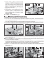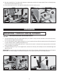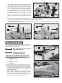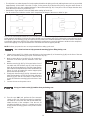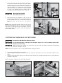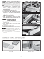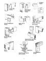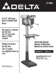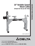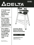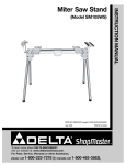
1
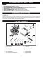
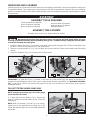
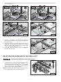
34-183
10" Contractors Saw
(Model 36-978/36-979)
Tenoning Jig
Gabarit à
tenonner
Espigadora
Instruction Manual
Manuel d’Utilisation
Manual de Instrucciones
FRANÇAIS (15)
ESPAÑOL (29)
www.deltamachinery.com
(800) 223-7278 - US
(800) 463-3582 - CANADA
A15102 - 01-13-06_RevA
Copyright © 2006 Delta Machinery
TABLE OF CONTENTS
IMPORTANT SAFETY INSTRUCTIONS . . . . . . . . . . . . . . . . . . . . . . . . . . . . . . . . . . . . . . . . . . . . . . . . . . . . . . . . . . . 2
SAFETY GUIDELINES. . . . . . . . . . . . . . . . . . . . . . . . . . . . . . . . . . . . . . . . . . . . . . . . . . . . . . . . . . . . . . . . . . . . . . . . . 3
GENERAL SAFETY RULES . . . . . . . . . . . . . . . . . . . . . . . . . . . . . . . . . . . . . . . . . . . . . . . . . . . . . . . . . . . . . . . . . . . . 3
ADDITIONAL SPECIFIC SAFETY RULES . . . . . . . . . . . . . . . . . . . . . . . . . . . . . . . . . . . . . . . . . . . . . . . . . . . . . . . . . 4
FUNCTIONAL DESCRIPTION . . . . . . . . . . . . . . . . . . . . . . . . . . . . . . . . . . . . . . . . . . . . . . . . . . . . . . . . . . . . . . . . . . 4
CARTON CONTENTS . . . . . . . . . . . . . . . . . . . . . . . . . . . . . . . . . . . . . . . . . . . . . . . . . . . . . . . . . . . . . . . . . . . . . . . . . 4
ASSEMBLY . . . . . . . . . . . . . . . . . . . . . . . . . . . . . . . . . . . . . . . . . . . . . . . . . . . . . . . . . . . . . . . . . . . . . . . . . . . . . . . . . 5
OPERATION . . . . . . . . . . . . . . . . . . . . . . . . . . . . . . . . . . . . . . . . . . . . . . . . . . . . . . . . . . . . . . . . . . . . . . . . . . . . . . . . 8
TROUBLESHOOTING . . . . . . . . . . . . . . . . . . . . . . . . . . . . . . . . . . . . . . . . . . . . . . . . . . . . . . . . . . . . . . . . . . . . . . 14
SERVICE . . . . . . . . . . . . . . . . . . . . . . . . . . . . . . . . . . . . . . . . . . . . . . . . . . . . . . . . . . . . . . . . . . . . . . . . . . . . . . . . . . 14
ACCESSORIES . . . . . . . . . . . . . . . . . . . . . . . . . . . . . . . . . . . . . . . . . . . . . . . . . . . . . . . . . . . . . . . . . . . . . . . . . . . . 14
WARRANTY. . . . . . . . . . . . . . . . . . . . . . . . . . . . . . . . . . . . . . . . . . . . . . . . . . . . . . . . . . . . . . . . . . . . . . . . . . . . . . . . 14
FRANÇAIS . . . . . . . . . . . . . . . . . . . . . . . . . . . . . . . . . . . . . . . . . . . . . . . . . . . . . . . . . . . . . . . . . . . . . . . . . . . . . . . . . 15
ESPAÑOL. . . . . . . . . . . . . . . . . . . . . . . . . . . . . . . . . . . . . . . . . . . . . . . . . . . . . . . . . . . . . . . . . . . . . . . . . . . . . . . . . . 29
IMPORTANT SAFETY INSTRUCTIONS
Read and understand all warnings and operating instructions before using any tool or equipment.
When using tools or equipment, basic safety precautions should always be followed to reduce the risk of
personal injury. Improper operation, maintenance or modification of tools or equipment could result in serious
injury and property damage. There are certain applications for which tools and equipment are designed. Delta
Machinery strongly recommends that this product NOT be modified and/or used for any application other than
for which it was designed.
If you have any questions relative to its application DO NOT use the product until you have written Delta Machinery
and we have advised you.
Online contact form at www.deltamachinery.com
Postal Mail: Technical Service Manager
Delta Machinery
4825 Highway 45 North
Jackson, TN 38305
(IN CANADA: 125 Mural St. Suite 300, Richmond Hill, ON, L4B 1M4)
Information regarding the safe and proper operation of this tool is available from the following sources:
Power Tool Institute
1300 Sumner Avenue, Cleveland, OH 44115-2851
www.powertoolinstitute.org
National Safety Council
1121 Spring Lake Drive, Itasca, IL 60143-3201
American National Standards Institute, 25 West 43rd Street, 4 floor, New York, NY 10036 www.ansi.org
ANSI 01.1Safety Requirements for Woodworking Machines, and the U.S. Department of Labor regulations www.osha.gov
SAVE THESE INSTRUCTIONS!
2
SAFETY GUIDELINES - DEFINITIONS
It is important for you to read and understand this manual. The information it contains relates to protecting YOUR
SAFETY and PREVENTING PROBLEMS. The symbols below are used to help you recognize this information.
Indicates an imminently hazardous situation which, if not avoided, will result in death or serious injury.
Indicates a potentially hazardous situation which, if not avoided, could result in death or serious injury.
Indicates a potentially hazardous situation which, if not avoided, may result in minor or moderate injury.
Used without the safety alert symbol indicates potentially hazardous situation which, if not avoided, may result in
property damage.
GENERAL SAFETY RULES
Failure to follow these rules may result in serious personal injury.
1.
2.
3.
4.
5.
6.
7.
8.
9.
10.
11.
12.
13.
14. USE THE PROPER EXTENSION CORD. Make sure your
extension cord is in good condition. When using an extension
cord, be sure to use one heavy enough to carry the current
your product will draw. An undersized cord will cause a drop in
line voltage, resulting in loss of power and overheating. See the
Extension Cord Chart for the correct size depending on the cord
length and nameplate ampere rating. If in doubt, use the next
heavier gauge. The smaller the gauge number, the heavier the
cord.
15. SECURE THE WORKPIECE. Use clamps or a vise to hold the
workpiece when practical. Loss of control of a workpiece can
cause injury.
16. FEED THE WORKPIECE AGAINST THE DIRECTION OF THE
ROTATION OF THE BLADE, CUTTER, OR ABRASIVE SURFACE.
Feeding it from the other direction will cause the workpiece to be
thrown out at high speed.
17. DON’T FORCE THE WORKPIECE ON THE MACHINE. Damage
to the machine and/or injury may result.
18. DON’T OVERREACH. Loss of balance can make you fall into a
working machine, causing injury.
19. NEVER STAND ON THE MACHINE. Injury could occur if the tool
tips, or if you accidentally contact the cutting tool.
20. NEVER LEAVE THE MACHINE RUNNING UNATTENDED. TURN
THE POWER OFF. Don’t leave the machine until it comes to a
complete stop. A child or visitor could be injured.
21. TURN THE MACHINE “OFF”, AND DISCONNECT THE MACHINE
FROM THE POWER SOURCE before installing or removing
accessories, changing cutters, adjusting or changing set-ups.
When making repairs, be sure to lock the start switch in the “OFF”
position. An accidental start-up can cause injury.
22. MAKE YOUR WORKSHOP CHILDPROOF WITH PADLOCKS,
MASTER SWITCHES, OR BY REMOVING STARTER KEYS.
The accidental start-up of a machine by a child or visitor could
cause injury.
23. STAY ALERT, WATCH WHAT YOU ARE DOING, AND USE
COMMON SENSE. DO NOT USE THE MACHINE WHEN
YOU ARE TIRED OR UNDER THE INFLUENCE OF DRUGS,
ALCOHOL, OR MEDICATION. A moment of inattention while
operating power tools may result in injury.
24.
USE OF THIS TOOL CAN GENERATE
AND DISBURSE DUST OR OTHER AIRBORNE PARTICLES,
INCLUDING WOOD DUST, CRYSTALLINE SILICA DUST AND
ASBESTOS DUST. Direct particles away from face and body.
Always operate tool in well ventilated area and provide for proper
dust removal. Use dust collection system wherever possible.
Exposure to the dust may cause serious and permanent
respiratory or other injury, including silicosis (a serious lung
disease), cancer, and death. Avoid breathing the dust, and avoid
prolonged contact with dust. Allowing dust to get into your mouth
or eyes, or lay on your skin may promote absorption of harmful
material. Always use properly fitting NIOSH/OSHA approved
respiratory protection appropriate for the dust exposure, and
wash exposed areas with soap and water.
FOR YOUR OWN SAFETY, READ THE INSTRUCTION MANUAL
BEFORE OPERATING THE MACHINE. Learning the machine’s
application, limitations, and specific hazards will greatly
minimize the possibility of accidents and injury.
WEAR EYE AND HEARING PROTECTION. ALWAYS USE
SAFETY GLASSES. Everyday eyeglasses are NOT safety
glasses. USE CERTIFIED SAFETY EQUIPMENT. Eye protection
equipment should comply with ANSI Z87.1 standards. Hearing
equipment should comply with ANSI S3.19 standards.
WEAR PROPER APPAREL. Do not wear loose clothing, gloves,
neckties, rings, bracelets, or other jewelry which may get caught
in moving parts. Nonslip protective footwear is recommended.
Wear protective hair covering to contain long hair.
DO NOT USE THE MACHINE IN A DANGEROUS
ENVIRONMENT. The use of power tools in damp or wet locations
or in rain can cause shock or electrocution. Keep your work area
well-lit to prevent tripping or placing arms, hands, and fingers in
danger.
MAINTAIN ALL TOOLS AND MACHINES IN PEAK CONDITION.
Keep tools sharp and clean for best and safest performance.
Follow instructions for lubricating and changing accessories. Poorly
maintained tools and machines can further damage the tool or
machine and/or cause injury.
CHECK FOR DAMAGED PARTS. Before using the machine,
check for any damaged parts. Check for alignment of moving
parts, binding of moving parts, breakage of parts, and any other
conditions that may affect its operation. A guard or any other part
that is damaged should be properly repaired or replaced with
Delta or factory authorized replacement parts. Damaged parts
can cause further damage to the machine and/or injury.
KEEP THE WORK AREA CLEAN. Cluttered areas and benches
invite accidents.
KEEP CHILDREN AND VISITORS AWAY. Your shop is a potentially
dangerous environment. Children and visitors can be injured.
REDUCE THE RISK OF UNINTENTIONAL STARTING. Make sure
that the switch is in the “OFF” position before plugging in the
power cord. In the event of a power failure, move the switch to
the “OFF” position. An accidental start-up can cause injury. Do
not touch the plug’s metal prongs when unplugging or plugging in
the cord.
USE THE GUARDS. Check to see that all guards are in place,
secured, and working correctly to prevent injury.
REMOVE ADJUSTING KEYS AND WRENCHES BEFORE
STARTING THE MACHINE. Tools, scrap pieces, and other debris
can be thrown at high speed, causing injury.
USE THE RIGHT MACHINE. Don’t force a machine or an
attachment to do a job for which it was not designed. Damage to
the machine and/or injury may result.
USE RECOMMENDED ACCESSORIES. The use of accessories
and attachments not recommended by Delta may cause damage
to the machine or injury to the user.
3
ADDITIONAL SPECIFIC SAFETY RULES
Failure to follow these rules may result in serious personal injury.
1.
2.
3.
4.
5.
Disconnect the power source to the machine.
Make sure that the blade has come to a complete stop before adjusting the jig or the workpiece.
Keep both hands on the operating handles when operating the jig.
Replace the blade guard of the saw when the jig operation is complete.
Refer to the owner's manual of the saw for safety rules and other instructions.
FUNCTIONAL DESCRIPTION
FOREWORD
Your new 34-183 Tenoning Jig will help you produce good strong joints. Although you can use many methods for
joining wood, the classic mortise-and-tenon joint is one of the strongest and most widely used joints in woodworking.
This jig will help you perform this task much easier than ever before.
CARTON CONTENTS
3
4
2
1
5
6
9
8
7
14
13
12
11
10
1. Base and Vertical Work Support Assembly
8.
M10 x 20mm Socket Head Screw
2. Clamp Assembly
9.
Handles (2)
3. M8 Flat Washer
10.
2.5mm Hex Wrench
4. M8 x 50mm Socket Head Screw
11.
3mm Hex Wrench
5. Clamp Arm
12.
4mm Hex Wrench
6. M10 Lockwasher (2)
13.
6mm Hex Wrench
7. M10 x 25mm Socket Head Screw
14.
8mm Hex Wrench
4
UNPACKING AND CLEANING
Carefully unpack the machine and all loose items from the shipping container(s). Remove the protective coating from
all unpainted surfaces. This coating may be removed with a soft cloth moistened with kerosene. (Do not use acetone,
gasoline or lacquer thinner for this purpose.) After cleaning, cover the unpainted surfaces with a good quality household
floor paste wax.
ASSEMBLY
ASSEMBLY TOOLS REQUIRED
2.5mm Hex Wrench (Supplied)
3mm Hex Wrench (Supplied)
8mm Hex Wrench (Supplied)
4mm Hex Wrench (Supplied)
6mm Hex Wrench (Supplied)
Adjustable Wrench
ASSEMBLY TIME ESTIMATE
Assembly time for this unit is approximately 30 minutes.
Disconnect the machine from the power source and remove the blade guard before using the
tenoning jig. Reinstall the blade guard immediately after jig use is complete. Always unplug the machine before
removing or installing the blade guard.
1. Fasten the clamp arm (A) Fig. 3 to the back of the work support plate using the M10 x 25mm socket head screw
(B), M10 x 25mm socket head screw (X), and lockwashers.
2. Fasten the clamp assembly (C) Fig. 4 to the clamp arm (A) using the M8 x 50mm socket head screw (D) and flat
washer.
3. Fasten the handles (F) Fig. 4 to the clamp arm (A) and base (H).
F
Fig. 4
X
C
E
B
A
G
Fig. 3
H
D
A
IMPORTANT: The guide bar (G) Fig. 4, located on the base (H) of the tenoning jig, was preset at the factory for
operation on right-tilting arbor saws. If your saw is a right-tilt saw, follow the instructions for “ALIGNING TENONING
JIG”. If your saw is a left-tilt saw, relocate the guide bar (G) Fig. 4 on the base (H) of the tenoning jig by using the
following directions.
FOR LEFT-TILTING ARBOR SAWS ONLY
NOTE: Position the tenoning jig in the miter gauge
slot to the left of the blade.
4. Loosen the small lock handle (J) Fig. 5. Remove the
large lock handle (K) and flat washer (L) Fig. 5 from the
tenoning jig.
K
NOTE: Both lock handles (J) and (K) Fig. 5 are springloaded and can be repositioned by pulling out on the
handle and repositioning it on the nut located underneath
the handle.
J
L
Fig. 5
5
6. Use the supplied 3mm hex wrench to loosen the set screw (M) Fig. 6. Remove the micro-adjustment assembly (N) from
the tenoning jig (Fig. 7).
Fig. 6
Fig. 7
M
N
P
G H
R
R
S
H
Fig. 8
Fig. 9
7. Lift the jig assembly (P) Fig. 8 from the base (H).
Remove the two button head screws and flat washers
(R) from the base.
8. Slide the base (H) Fig. 9 forward until the two holes (S)
are aligned with the holes in the guide bar (G). Fasten
the base to the guide bar with the two button head
screws and flat washers (R) (Fig. 10).
9. Reassemble the items that were removed in STEPS 4,
5, and 6 in reverse order.
G H
R
Fig. 10
ADJUSTING THE GUIDE BAR TO THE TABLE SLOT
Disconnect the Machine from the Power Source!
B
1.
The tenoning jig is furnished with an adjustable guide
bar (A) Fig. 11 that allows the jig to custom-fit to your
saw, eliminating side-to-side play. Also, a T-slot washer
(B) is on each end of the guide bar (A) to keep the
tenoning jig from lifting during operation.
A
C
NOTE: Remove the T-slot washers (B) if your table saw is
not equipped with T-slotted miter gauge slots.
Fig. 11
6
2.
3.
4.
5.
Place the tenoning jig guide bar (A) Fig. 12 into the left
miter slot (D) and slide the tenoning jig back and forth
to determine if it has side-to-side play. If the tenoning jig
slides easily through the miter slot without side-to-side
play, no adjustment is necessary. However, if the tenoning
jig fits too snugly, or if there is excessive play between the
guide bar (A) and the miter slot (D), adjust the jig, using
instructions 3-5 of this section.
Remove the jig from machine and place it upside down
(Fig. 11).
Use the 2.5mm hex wrench to turn the screws (C) Fig. 11
clockwise for a snug fit, or counter-clockwise for a looser
fit.
Insert the tenoning jig back into the miter slot of the
machine to determine if the fit is suitable, or if further
adjustment is required.
Fig. 12
F
G
E
D
A
ALIGNING THE TENONING JIG
Disconnect the Machine from the Power Source!
1.
2.
3.
4.
Place the tenoning jig guide bar (A) Fig. 12 into the left miter gauge slot.
Use a square (E) Fig. 12 to see if the vertical work support plate (F) is 90 degrees to the saw table. If an adjustment is necessary,
loosen the lock handle (G) and the set screw (H) Fig. 13, move the vertical work support plate (F) until it is 90 degrees to the
table, and tighten the lock handle (G).
With the vertical work support plate (F) Fig. 13 adjusted, tighten the set screw (H) until it bottoms. This set screw (H) enables
you to rapidly position the vertical work support (F) 90 degrees to the table after it has been tilted.
Use a square (E) Fig. 14 to see if the face of the backstop (J) is 90 degrees to the saw table. If an adjustment is necessary,
loosen lock lever (K), adjust backstop (J) accordingly and tighten lever (K).
J
K
F
H
E
Fig. 14
Fig. 13
5.
6.
Loosen the nut (L) Fig. 15, and turn the set screw (M) counter-clockwise, two or three times.
Loosen the two lock levers (N) and (P) Fig. 16, and move the jig (R) until the vertical work support plate (F) is against the saw
blade and tighten the lever (N).
NOTE: The lock levers (N) and (P) are spring-loaded and can be repositioned by pulling up on the handles and repositioning them
on the nut located underneath the handles.
7. Check to see if the vertical work-support plate (F) Fig. 16 is parallel to the saw blade.
8. If an adjustment is necessary, loosen the lever (N) Fig. 16. Rotate the knob (S) clockwise as far as possible to align the holes
(T) with the guide bar (X) and to gain access to the set screws. Loosen the two screws inside the holes (T) and move the jig (R)
until the vertical work-support plate (F) is parallel to the saw blade. Tighten the two screws inside the holes (T).
9. Move the jig (R) Fig. 16 1/8" away from blade so that the vertical work-support plate (F) clears saw blade. Tighten the lever
(N).
10. Rotate the knob (S) Fig. 16 counter-clockwise until the collar (V) is halfway between the knob (S) and the side of the jig (R).
Tighten the lever (P).
P
T
V
S
F
M
F
L
X
N
R
T
Fig. 16
Fig. 15
7
11. Turn the screw (M) Fig. 17 clockwise until it bottoms to prevent the vertical work-support plate (F) from accidentally being
moved into the blade. Tighten the nut (L).
12. Loosen the screw (Y) Fig. 19, and adjust the pointer (Z) to the “1/8" mark on scale.
Y
M
Z
F
L
Fig. 18
Fig. 17
OPERATION
OPERATIONAL CONTROLS AND ADJUSTMENTS
Disconnect the Machine from the Power Source!
1. For rapid adjustment of the work support plate (A) Fig. 19, toward or away from the saw blade, loosen levers (B) and (C)
and move jig (D). Tighten levers (B) and (C).
2. You can fine-adjust the work support plate (A) Fig. 19, by loosening the lever (B) and rotating the knob (E) until plate (A)
is at the desired position. Tighten the lever (B) Fig. 19.
3. To tilt the vertical work support plate (A) Fig. 19, loosen the lock lever (F), tilt vertical work support plate to the desired
angle, and tighten lock lever (F).
4. To adjust backstop (G) Fig. 20, for angle tenons, loosen lock lever (H), tilt backstop (G) to the desired angle and
tighten lever (H).
IMPORTANT: The tenoning jig is not equipped with a bevel scale for the positioning of the backstop (G) Fig. 20 or the support
plate (A) Fig. 19. Cut the workpiece to the desired angle prior to the jig set up and use it as the angle reference.
E
G
C
A
F
Fig. 19
D
B
Fig. 20
8
H
5.
6.
7.
G
M
The tenoning jig features a positive stop to ensure fast
and accurate positioning of the backstop (G) Fig. 21
at 90 degrees to the saw table. To check and adjust
the positive stop at 90 degrees, loosen lock handle (H)
Fig. 21, and place one end of a combination square (J)
on the saw table and the other end against backstop
(G). If the backstop is not 90 degrees to the table,
loosen the locknut (K) Fig. 21, and tighten or loosen
the adjustment screw (L) until the head of the screw
contacts the casting on the vertical plate (M) at 90
degrees. Tighten the locknut (K) and lock the handle
(H).
J
L
H
K
Fig. 21
To eliminate chip-out when performing cheek cuts, you can fasten an auxiliary wooden backup board (P) Fig. 23 to the
backstop (G) Fig. 22 with two wood screws through the two pre-drilled holes (N).
You can also fasten a block of wood to the vertical support plate (R) Fig. 23, through four pre-drilled holes (S) to prevent
the saw blade from contacting the jig.
G
P
R
N
S
Fig. 23
Fig. 22
TENONING JIG USE
This jig is intended to perform cheek cuts only. Cheek cuts
are made prior to the shoulder cuts, which are made on a
table saw using the miter gauge.
D
Keep your hands on the jig handles
when performing cuts.
Disconnect the Machine
from the Power Source!
E
A
C
B
STRUCTURE OF A MORTISE AND TENON JOINT
Parts of a simple or “blind” joint are (Fig. 24):
A. Structural Shoulder
B. Cheek
C. Cosmetic Shoulder
D. Mortise
E. Mortise Walls
Lay out the mortise and tenon on the workpieces (Fig. 25),
but keep these items in mind when laying out the joints:
• To avoid premature joint failure, avoid locating a tenon in
a disfigured part of the grain (a knot), for unpredictable
movement of the joint may occur. Use straight, flat,
common-grained stock.
• The tenon will shrink in width away from the mortise
walls, possibly revealing the mortised hole. When
possible, produce tenons with shoulders on all
four sides - two structural and two cosmetic - to conceal
the mortised hole when wood movement occurs.
Fig. 24
Fig. 25
9
• The objective is to make the parts fit closely together. Maximize the gluing surface by making the tenon as long as possible
(approximately 1/2 the width of the stile or longer, if using narrow stock). Balance the joint by using the same amount of
wood in the tenon as in the combined thickness of the mortise walls (Fig. 26). If one piece of wood is larger than the other,
make the tenon as thick as possible (Fig. 27).
• Remember to figure the kerf of the saw blade when setting up for the cut.
• Cut all mortises first. Make the mortise 1/16" deeper than the length of the tenon to allow for glue.
Fig. 27
Fig. 26
You can use several different methods to cut a mortise and tenon. The following information illustrates one of the easiest and
safest methods and utilizes cheek cuts first, then shoulder cuts. Use a base stop (F) Fig. 28 that is the same thickness as the
base plate (G) of the tenoning jig (H) and spacer block (K) that is the combined thickness of the tenon and the saw blade,
to make the cutting more efficient. This method eliminates possible errors caused by thickness variations in the workpiece,
and avoids trapping cut-off pieces between the saw blade and vertical support plate (N).
NOTE: Perform your practice cuts on scrap material before cutting good wood.
Use a slow feed rate to help prevent the tenoning jig from lifting during a cut.
1.
Clamp a base stop (F) Fig. 28 (the same thickness as the base plate (G) of the tenoning jig (H)) on the front of the saw
table. This will allow tenoning jig to pass over the base stop (F).
2.
Make a spacer block of wood (K) Fig. 28, equal to the
thickness of the tenon plus the thickness of the saw
blade.
3.
4.
5.
Fig. 28
With the tenoning jig (H) Fig. 28 located at the front of
saw table and over the base stop (F), load the spacer
block (K) and the workpiece (L). Securely clamp both in
place with the clamp handle (M). Make certain that both
pieces of wood are against the vertical support plate
(N) and the backup board (P).
Gently push the tenoning jig (H) Fig. 28 toward the saw
blade until workpiece is near the saw blade. Adjust the
tenoning jig (H) and the saw blade to make the first
cheek cut. Return the tenoning jig (H) to the front of saw
table.
Connect the saw to the power source.
N
P
M
F
Keep your hands on the jig handles when performing cuts.
6.
K
L
Turn the saw “ON” and perform the first structural
cheek cut (Fig. 29). Feed the tenoning jig toward the
saw blade at a slow feed rate until the saw blade has
exited the back of the workpiece. Turn the tool off
and allow the blade to come to a complete stop, then
slowly pull the tenoning jig back to the position shown
in Fig. 28.
Fig. 29
10
G
H
7.
Loosen the clamp (M) Fig. 28. Remove the spacer
block (K) and secure the workpiece (L) Fig. 29 in place.
Keep the same face of the workpiece (L) against the
vertical support plate (N) and the backup board (P).
Turn the machine “on”, perform the second structural
cheek cut, and turn the machine “off”. Allow the blade
to come to a complete stop, then slowly pull the
tenoning jig back to the position shown in Fig. 28.
L
P
N
Disconnect the Machine
from the Power Source!
8.
Fig. 30
Load and secure the workpiece (L) Fig. 31 on the
tenoning jig and adjust the jig to perform the third and
fourth cosmetic cheek cuts. Connect the machine to
the power source, turn the saw “on”, and make the
cuts.
L
NOTE: When cutting the cosmetic cheek cuts, do not use
the spacer block (K) Fig. 28. You can turn the workpiece
180 degrees. The discrepancies in the workpiece are not as
critical when cutting the cosmetic cheeks as compared to
the structural cheeks.
N
Fig. 31
CUTTING THE SHOULDERS OF THE TENON
Disconnect the Machine from the Power Source
To avoid personal injury or damage to the machine, always use a cross-cut blade to perform the
shoulder cuts of the tenon.
When performing the shoulder cuts of the tenon, do not cut into the cheeks of the tenon. It will greatly
reduce the strength of the joint.
NOTE: Perform your practice cuts on scrap material before cutting good wood.
1.
2.
3.
Remove the tenoning jig from the machine.
Lay the workpiece (L) Fig. 32 on the saw table and adjust the saw blade (R) to cut the structural shoulders of the
tenon.
Clamp a wooden stop block (S) Fig. 33 to the front of the saw fence (T), and adjust the saw fence to cut the structural
shoulders of the tenon.
NOTE: Remember to figure in the width of the saw blade.
L
W
S
R
T
L
Fig. 33
Fig. 32
11
X
Position the wooden stop block (S)
Fig. 34 in front of the saw blade to prevent the workpiece
from being trapped between the saw fence and the saw,
causing kickback. Make sure that the workpiece is clear
of the wooden stop block (S) before contacting the saw
blade.
4. Use a miter gauge (W) Fig. 34, equipped with a backup
board (X), to position the workpiece (L) so that you
can cut the structural shoulders. Make certain that the
workpiece (L) is against the wooden stop block (S) and
the backup board (X).
5. Connect the machine to the power source.
6. Turn the machine “ON” and perform the structural
shoulder cut by slowly pushing the miter gauge (W)
Fig. 34 toward the saw blade until the saw blade is
completely through the workpiece. Turn the machine
“OFF”. Wait for the blade to come to a complete
stop and remove the cut-off piece.
7. Return the miter gauge (W) Fig. 34 to the position
shown, and perform the other structural shoulder cut in
the same manner.
W
T
S
X
L
Fig. 34
M
Disconnect the Machine
from the Power Source!
L
8.
Fig. 35 illustrates workpiece (L) with the two structural
shoulders (M) cut.
9. Adjust the blade height to perform the cosmetic
shoulder cuts.
10. Connect the saw to power source.
11. Perform the cosmetic shoulder cuts in the same manner
as the structural shoulder cuts.
Fig. 35
When performing the shoulder cuts of
the tenon, do not cut into the cheeks of the tenon. It will
greatly reduce the strength of the joint.
12. Fig. 36 illustrates a simple, or “blind” mortise-andtenon joint.
Fig. 36
EXAMPLES OF MORTISE-AND-TENON JOINTS
OPEN JOINT
MITERED JOINT
12
MITERED
TENON
HAUNCHED
TENON
TENON
ENDS
MITERED
CONCEALED
HAUNCHED
TENON
SAW
CUTS
MORTISE
THROUGH-WEDGED
TENON
CHEEK OF
TENON
SHOULDER OF
TENON
SIMPLE MORTISE
AND TENON
BARE FACED
TENON
WEDGE
BLIND-WEDGED
TENON
RABBET
TENON WITH LONG AND
SHORT SHOULDERS
SPLINE
STUB
TENON
SPLINE GROOVE
(SINGLE SAW CUT)
MORTISE AND TENON
WITH SPLINES
13
OPEN MORTISE
TENON
TROUBLESHOOTING
For assistance with your machine, visit our website at www.deltamachinery.com for a list of service centers or call the
DELTA Machinery help line at 1-800-223-7278 (In Canada call 1-800-463-3582).
SERVICE
REPLACEMENT PARTS
Service Center, visit our website at www.deltamachinery.
com or call our Customer Care Center at 1-800-223-7278.
All repairs made by our service centers are fully guaranteed
against defective material and workmanship. We cannot
guarantee repairs made or attempted by others.
Use only identical replacement parts. For a parts list or to
order parts, visit our website at servicenet.deltamachinery.
com. You can also order parts from your nearest factoryowned branch, or by calling our Customer Care Center at
1-800-223-7278 to receive personalized support from highlytrained technicians.
You can also write to us for information at Delta Machinery,
4825 Highway 45 North, Jackson, Tennessee 38305 Attention: Product Service. Be sure to include all of the
information shown on the nameplate of your tool (model
number, type, serial number, etc.)
SERVICE AND REPAIRS
All quality tools will eventually require servicing and/or
replacement of parts. For information about Delta Machinery,
its factory-owned branches, or an Authorized Warranty
ACCESSORIES
A complete line of accessories is available from your Delta Supplier, Porter-Cable • Delta Factory Service Centers, and
Delta Authorized Service Stations. Please visit our Web Site www.deltamachinery.com for a catalog or for the name of
your nearest supplier.
Since accessories other than those offered by Delta have not been tested with this product, use
of such accessories could be hazardous. For safest operation, only Delta recommended accessories should be
used with this product.
WARRANTY
To register your tool for warranty service visit our website at www.deltamachinery.com.
Two Year Limited New Product Warranty
Delta will repair or replace, at its expense and at its option, any new Delta machine, machine part, or machine accessory which in normal
use has proven to be defective in workmanship or material, provided that the customer returns the product prepaid to a Delta factory service
center or authorized service station with proof of purchase of the product within two years and provides Delta with reasonable opportunity
to verify the alleged defect by inspection. For all refurbished Delta product, the warranty period is 180 days. Delta may require that electric
motors be returned prepaid to a motor manufacturer’s authorized station for inspection and repair or replacement. Delta will not be responsible
for any asserted defect which has resulted from normal wear, misuse, abuse or repair or alteration made or specifically authorized by anyone
other than an authorized Delta service facility or representative. Under no circumstances will Delta be liable for incidental or consequential
damages resulting from defective products. This warranty is Delta’s sole warranty and sets forth the customer’s exclusive remedy, with respect
to defective products; all other warranties, express or implied, whether of merchantability, fitness for purpose, or otherwise, are expressly
disclaimed by Delta.
14
The following are trademarks of PORTER-CABLE • DELTA (Las siguientes son marcas registradas de PORTER-CABLE • DELTA S.A.) (Les marques suivantes sont
des marques de fabriquant de la PORTER-CABLE • DELTA): Auto-Set®, BAMMER®, B.O.S.S.®, Builder’s Saw®, Contractor’s Saw®, Contractor’s Saw II™, Delta®,
DELTACRAFT®, DELTAGRAM™, Delta Series 2000™, DURATRONIC™, Emc²™, FLEX®, Flying Chips™, FRAME SAW®, Grip Vac™, Homecraft®, Jet-Lock®,
JETSTREAM®, ‘kickstand®, LASERLOC®, MICRO-SET®, Micro-Set®, MIDI LATHE®, MORTEN™, NETWORK™, OMNIJIG®, POCKET CUTTER®, PORTA-BAND®,
PORTA-PLANE®, PORTER-CABLE®&(design), PORTER-CABLE®PROFESSIONAL POWER TOOLS, PORTER-CABLE REDEFINING PERFORMANCE™, Posi-Matic®,
Q-3®&(design), QUICKSAND®&(design), QUICKSET™, QUICKSET II®, QUICKSET PLUS™, RIPTIDE™&(design), SAFE GUARD II®, SAFE-LOC®, Sanding Center®,
SANDTRAP®&(design), SAW BOSS®, Sawbuck™, Sidekick®, SPEED-BLOC®, SPEEDMATIC®, SPEEDTRONIC®, STAIR EASE®, The American Woodshop®&(design),
The Lumber Company®&(design), THE PROFESSIONAL EDGE®, THE PROFESSIONAL SELECT®, THIN-LINE™, TIGER®, TIGER CUB®, TIGER SAW®, TORQBUSTER®,
TORQ-BUSTER®, TRU-MATCH™, TWIN-LITE®, UNIGUARD®, Unifence®, UNIFEEDER™, Unihead®, Uniplane™, Unirip®, Unisaw®, Univise®, Versa-Feeder®, VERSAPLANE® , WHISPER SERIES®,WOODWORKER’S CHOICE™.
Trademarks noted with ™ and ® are registered in the United States Patent and Trademark Office and may also be registered in other countries. Las Marcas Registradas con
el signo de ™ y ® son registradas por la Oficina de Registros y Patentes de los Estados Unidos y también pueden estar registradas en otros países. Marques déposées,
indiquées par la lettre ™ et ®, sont déposées au Bureau des brevets d’invention et marques déposées aux Etats-Unis et pourraient être déposées aux autres pays.
Delta Machinery
4825 Highway 45 North
Jackson, TN 38305
www.deltamachinery.com
44