1
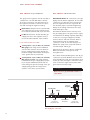
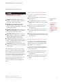
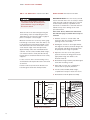
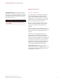
D UAL F UEL R ANGES
I NSTALLATION I NSTRUCTIONS
C O N TA C T
I N F O R M AT I O N
Wolf Customer
Service:
800-332-9513
Website:
wolfappliance.com
As you follow these instructions, you will
notice WARNING and CAUTION symbols.
This blocked information is important for the
safe and efficient installation of Wolf equipment. There are two types of potential
hazards that may occur during installation.
signals a situation where minor injury or
product damage may occur if you do not
follow instructions.
states a hazard that may cause serious
injury or death if precautions are not
followed.
Another footnote we would like to identify is
IMPORTANT NOTE: This highlights information that is especially relevant to a problemfree installation.
WOLF ® is a registered trademark of Wolf Appliance, Inc.
W O L F D UA L F U E L R A N G E S
I N S TA L L AT I O N R E Q U I R E M E N T S
IMPORTANT NOTE: This installation must
be completed by a qualified installer,
service agency or gas supplier.
IMPORTANT NOTE: Save these Installation
Instructions for the local inspector’s use.
Please read the entire Installation Instructions prior to installation.
Installer: please retain these instructions
for local inspector’s reference, then leave
them with the homeowner.
Homeowner: please read and keep these
instructions for future reference and be sure
to read the entire Use & Care Information
prior to use.
IMPORTANT NOTE: This appliance must be
installed in accordance with National Electrical
Codes, as well as all state, municipal and local
codes. The correct voltage, frequency and
amperage must be supplied to the appliance
from a dedicated, grounded circuit which is
protected by a properly sized circuit breaker or
time delay fuse. The proper voltage, frequency,
and amperage ratings are listed on the product
rating plate.
Record the model and serial numbers before
installing the dual fuel range. Both numbers
are listed on the rating plate, located at the far
right of the bottom of the control panel
assembly just above the oven door.
Model Number
Serial Number
If the information in this book is
not followed exactly, a fire or
explosion may result, causing
property damage, personal injury
or death.
IMPORTANT NOTE:
Installation and service must be
performed by a qualified installer,
service agency or the gas supplier.
Warranty service must be performed
by a Wolf authorized service center.
Do not store or use gasoline or
other flammable vapors and liquids
in the vicinity of this or any other
appliance.
A ventilation hood is recommended
for use with the Wolf dual fuel range.
WHAT TO DO IF YOU SMELL GAS:
Do not try to light any appliance.
Do not touch any electrical switch.
Do not use any phone in your
building.
Immediately call your gas supplier
from a neighbor’s phone. Follow the
gas supplier’s instructions.
If you cannot reach your gas
supplier, call the fire department.
3
W O L F D UA L F U E L R A N G E S
B E F O R E YO U S TA RT
Proper installation is your responsibility.
Installations must be performed by a
qualified or licensed contractor, plumber or
gas fitter, qualified or licensed by the state,
province or region where this appliance is
being installed. You must also ensure that
electrical installation is adequate and
conforms with all local codes and
ordinances.
Wolf dual fuel ranges are manufactured for
use with natural gas or LP gas. Please
check product rating plate for type of gas
needed.
Proper gas supply must be available; refer
to Gas Supply Requirements on page 13.
Electrical ground is required; see Electrical
Requirements on page 15.
Check the location where the range will be
installed. The location should be away from
strong draft areas, such as windows, doors
and strong heating vents or fans. Do not
obstruct the flow of air. The area in which
you are installing this appliance must have
an adequate supply of fresh air to ensure
proper combustion and ventilation.
Make sure you have everything necessary
for proper installation. It is the responsibility of the installer to comply with the installation clearances specified on the product
rating plate. The rating plate is located at
the far right of the bottom of the control
panel assembly just above the oven door.
All openings in the wall or floor where the
range is to be installed must be sealed.
When installing the range under existing
cabinets where the installation does not
meet the minimum cabinet clearances,
install a ventilation hood or other noncombustible surface above the range to
avoid burn hazards. Refer to Minimum
Clearances on page 6.
4
C O M M O N W E A LT H O F M A S S A C H U S E T T S
Installations and repairs must be performed
by a qualified or licensed contractor,
plumber or gasfitter qualified or licensed by
the state, province, or region where this
appliance is being installed.
Only use gas shut-off valves approved for
use within the state, province, or region
where this appliance is being installed.
A flexible gas connector, when used, must
not exceed 3' (.9 m).
I N S TA L L AT I O N I N S T R U C T I O N S
V E N T I L AT I O N O P T I O N S
I N S TA L L AT I O N S P E C I F I C AT I O N S
IMPORTANT NOTE: It is recommended that
you operate the Wolf dual fuel range with a
Pro ventilation hood. Contact your Wolf dealer
for details.
Wolf dual fuel ranges come in 30" (762), 36"
(914), 48" (1219) and 60" (1524) widths.
Illustrations on pages 7–10 provide the overall
dimensions and installation specifications for
each width of dual fuel range.
Pro Wall Hood – 22" (559), 24" (610) or 27"
(686) depths and 30" (762) to 66" (1676)
widths in classic stainless steel.
Pro Island Hood – 36" (914) to 66" (1676)
widths in classic stainless steel.
Pro Hood Liner – available in widths to
accommodate 30" (762) to 60" (1524) hood
shells.
All Pro ventilation hoods have welded seams,
sealed halogen lighting and removable, dishwasher-safe stainless steel filters.
Each range is designed to fit between cabinets
set at the distance specified by the unit. For
example, a 36" (914) range will fit a 36"
opening. The exception is the 60" (1524) unit
which will require a 60 1/4" (1530) opening.
IMPORTANT NOTE: Cabinet opening dimensions shown in the Installation Specifications
illustrations must be used. These dimensions
provide for required clearances.
Blower requirements may vary due to length
of duct work and number of angles. The basic
recommendation is 1 CFM per 100 Btu/hr.
Always consult your HVAC professional for
more concise blower requirements.
Each unit is designed with a terminal block on
the rear of the range. The terminal block will
also accept an appliance power cord. Have a
qualified electrician or installer wire your unit
from the electrical supply, through the
knockout in the unit base and to the terminal
block on the range.
IMPORTANT NOTE: When installing a ventilation hood, refer to the specific requirements
of the hood for the minimum dimension to
countertop.
IMPORTANT NOTE: Locate the electrical
supply within dimensions shown in the
Installation Specifications illustrations and
flush with back wall.
ACCESSORIES
Optional accessories are available
through your
Wolf dealer. To
obtain local dealer
information, visit
the Showroom
Locator section of
our website,
wolfappliance.com.
Refer to the Installation Specifications illustration for your model on pages 7–10 for the
exact rough opening dimensions and location
of the gas supply and electrical.
Wolf dual fuel ranges using natural gas will
operate up to an altitude of 8,000' (2438 m)
without any adjustment. Natural gas and LP
gas installations from 8,000' (2438 m) to
11,000' (3353 m) need the high altitude conversion kit. Contact your Wolf dealer for details.
Dimensions in parentheses are in
millimeters unless otherwise specified.
5
W O L F D UA L F U E L R A N G E S
I N S TA L L AT I O N S P E C I F I C AT I O N S
MINIMUM CLEARANCES
I S L A N D | P E N I N S U L A I N S TA L L A T I O N S
IMPORTANT NOTE: Caution must be used in
planning the proper installation of the Wolf
dual fuel range to avoid fire or damage to
adjacent cabinetry or kitchen equipment.
Be sure to follow the minimum clearances
established in the finished rough opening
dimensions.
For island installations, the range should
not be installed within an enclosure having an
adjacent rear wall less than 12" (305) from
the rear of the unit that rises above the
countertop.
Refer to the Installation Specifications
illustration for your model on pages 7–10 for
the exact rough opening dimensions.
Maintain the following clearances to
combustible materials:
Minimum 18" (457) clearance from bottom
of upper cabinet to countertop, within 6"
(152) minimum side clearance.
Minimum 30" (762) clearance between
countertop and bottom of wood or metal
cabinet, which is protected by not less than
1/4" (6) flame retardant millboard covered
with not less than No. 28 MSG sheet steel,
.015" (.4) stainless steel, or .024" (.6)
aluminum or .02" (.5) copper.
Minimum 36" (914) clearance between
countertop and bottom of an unprotected
wood or metal cabinet.
Bottom of ventilation hood must be 30"
(762) minimum to 36" (914) maximum from
countertop.
6
For peninsula installations, the range must
have a 6" (152) minimum clearance to the side
wall, left or right side, and 12" (305) minimum
clearance to the rear wall.
Refer to the Installation Specifications
illustration for your model on pages 7–10 for
the exact rough opening dimensions.
Failure to locate the range without the
proper clearances will result in a fire
hazard.
I N S TA L L AT I O N I N S T R U C T I O N S
30" (762) D UA L F U E L R A N G E
29 1/2" (749)
OVERALL DEPTH
27 1/2" (699)
9 1/4"
(235)
56 7/8"
(1445)
WITH 20"
RISER
36 7/8"
35 7/8"
(937)
OVERALL
HEIGHT TO
COOKING
SURFACE
(911)
24 1/4"
46 7/8"
(616)
(1191)
WITH 10"
RISER
OVERALL DIMENSIONS
Overall Width
29 7/8" (759)
Overall Height
(to cooking surface)
36 7/8" (937)
Overall Depth
29 1/2" (749)
41 7/8"
(1064)
WITH 5"
RISER
Opening Width
Dimensions may vary to
29 7/8" (759)
OVERALL WIDTH
30" (762)
± 1/ 8"
(3).
47" (1194)
LEGS AND CASTERS ALLOW
21/8" (54) HEIGHT ADJUSTMENT
I N S TA L L AT I O N S P E C I F I C AT I O N S
VENTILATION HOOD
30"min (762)
COUNTERTOP TO
6" min (152) COMBUSTIBLE
MATERIALS
TO
COMBUSTIBLE
MATERIALS
(BOTH SIDES)
30"min (762) TO
36"max (914)
TO BOTTOM OF
VENTILATION HOOD
30" (762)
FINISHED ROUGH
OPENING WIDTH
10" (254)
81/2" LOCATION
(216)
OF GAS
SUPPLY
13" max
(330)
18"min (457)
TO COUNTERTOP
36"
(914)
31/4"
36 7/8"
(937) TO
COOKING
SURFACE
(83)
13"
LOCATION OF GAS AND
(330)
ELECTRICAL EXTENDS 3" (76) LOCATION OF
ON FLOOR FROM BACK WALL ELECTRICAL
Dimensions in parentheses are in
millimeters unless otherwise specified.
ISLAND INSTALLATIONS: 12" (305) MINIMUM
CLEARANCE FROM BACK OF RANGE TO
COMBUSTIBLE REAR WALL ABOVE COUNTERTOP–
0" (0) TO NON-COMBUSTIBLE MATERIALS
7
W O L F D UA L F U E L R A N G E S
36" (914) D UA L F U E L R A N G E S
29 1/2" (749)
OVERALL DEPTH
27 1/2" (699)
9 1/4"
(235)
56 7/8"
OVERALL DIMENSIONS
(1445)
WITH 20"
RISER
35 7/8" (911)
Overall Width
46 7/8"
(1191)
WITH 10"
RISER
24 1/4"
(616)
Overall Height
(to cooking surface)
36 7/8" (937)
Overall Depth
29 1/2" (749)
Opening Width
36 7/8"
35 7/8"
(937)
OVERALL
HEIGHT TO
COOKING
SURFACE
(911)
41 7/8"
(1064)
WITH 5"
RISER
36" (914)
Dimensions may vary to
± 1/ 8"
(3).
357/8" (911)
OVERALL WIDTH
47" (1194)
LEGS AND CASTERS ALLOW
21/8" (54) HEIGHT ADJUSTMENT
I N S TA L L A T I O N S P E C I F I C AT I O N S
IMPORTANT NOTE:
In non-island applications, a minimum
5" (127) riser is
required for Model
DF366 and minimum
10" (254) riser
required for Models
DF364C and DF364G
installed against a
combustible surface.
The island trim and
5" (127) riser may
only be used against
a non-combustible
surface for Models
DF364C and DF364G.
VENTILATION HOOD
36"min (914)
COUNTERTOP
TO COMBUSTIBLE
MATERIALS
6" min (152)
30"min (762) TO
36"max (914)
44"min (1118)
FOR CHARBROILER
TO
COMBUSTIBLE
MATERIALS
(BOTH SIDES)
TO BOTTOM OF
VENTILATION HOOD
36" (914)
FINISHED ROUGH OPENING WIDTH
13" max
(330)
18"min (457)
TO COUNTERTOP
36"
(914)
81/2"
(216)
LOCATION OF GAS AND
ELECTRICAL EXTENDS 3" (76)
ON FLOOR FROM BACK WALL
8
15" (381)
LOCATION
OF GAS
SUPPLY
19" (483)
LOCATION OF
ELECTRICAL
31/4"
36 7/8"
(937) TO
COOKING
SURFACE
(83)
ISLAND INSTALLATIONS: 12" (305) MINIMUM
CLEARANCE FROM BACK OF RANGE TO
COMBUSTIBLE REAR WALL ABOVE COUNTERTOP–
0" (0) TO NON-COMBUSTIBLE MATERIALS
I N S TA L L AT I O N I N S T R U C T I O N S
48" (1219) D UA L F U E L R A N G E S
29 1/2" (749)
OVERALL DEPTH
27 1/2" (699)
9 1/4"
(235)
56 7/8"
(1445)
WITH 20"
RISER
36 7/8"
35 7/8"
(937)
OVERALL
HEIGHT TO
COOKING
SURFACE
(911)
24 1/4"
46 7/8"
(616)
(1191)
WITH 10"
RISER
41 7/8"
(1064)
WITH 5"
RISER
OVERALL DIMENSIONS
47 7/8" (1216)
Overall Width
Overall Height
(to cooking surface)
36 7/8" (937)
Overall Depth
29 1/2" (749)
Opening Width
48" (1219)
Dimensions may vary to
47 7/8" (1216)
OVERALL WIDTH
± 1/ 8"
(3).
47" (1194)
LEGS AND CASTERS ALLOW
21/8" (54) HEIGHT ADJUSTMENT
I N S TA L L AT I O N S P E C I F I C AT I O N S
VENTILATION HOOD
36"min (914)
COUNTERTOP
TO COMBUSTIBLE
MATERIALS
6" min (152)
30"min (762) TO
36"max (914)
44"min (1118)
FOR CHARBROILER
TO
COMBUSTIBLE
MATERIALS
(BOTH SIDES)
TO BOTTOM OF
VENTILATION HOOD
48" (1219)
FINISHED ROUGH OPENING WIDTH
13" max
IMPORTANT NOTE:
In non-island applications, a minimum
10" (254) riser is
required for all 48"
(1219) models
installed against a
combustible surface.
The island trim and
5" (127) riser may
only be used against
a non-combustible
surface.
(330)
18"min (457)
TO COUNTERTOP
36"
(914)
10"
24" (610)
(254)
LOCATION
OF GAS
SUPPLY
31/4"
36 7/8"
(937) TO
COOKING
SURFACE
(83)
13"
LOCATION OF GAS AND
ELECTRICAL EXTENDS 3" (76)
ON FLOOR FROM BACK WALL
(330)
LOCATION OF
ELECTRICAL
Dimensions in parentheses are in
millimeters unless otherwise specified.
ISLAND INSTALLATIONS: 12" (305) MINIMUM
CLEARANCE FROM BACK OF RANGE TO
COMBUSTIBLE REAR WALL ABOVE COUNTERTOP–
0" (0) TO NON-COMBUSTIBLE MATERIALS
9
W O L F D UA L F U E L R A N G E S
60" (1524) D UA L F U E L R A N G E S
29 1/2" (749)
OVERALL DEPTH
27 1/2" (699)
9 1/4"
(235)
56 7/8"
OVERALL DIMENSIONS
Overall Width
60 1/8" (1527)
Overall Height
(to cooking surface)
36 7/8" (937)
Overall Depth
29 1/2" (749)
Opening Width
(1445)
WITH 20"
RISER
36 7/8"
35 7/8"
(937)
OVERALL
HEIGHT TO
COOKING
SURFACE
(911)
24 1/4"
46 7/8"
(616)
(1191)
WITH 10"
RISER
41 7/8"
(1064)
WITH 5"
RISER
60 1/4" (1530)
Dimensions may vary to ± 1/8" (3).
60 1/8" (1527)
OVERALL WIDTH
47" (1194)
LEGS AND CASTERS ALLOW
21/8" (54) HEIGHT ADJUSTMENT
I N S TA L L A T I O N S P E C I F I C AT I O N S
IMPORTANT NOTE:
In non-island applications, a minimum
10" (254) riser is
required for all 60"
(1524) models
installed against a
combustible surface.
The island trim and
5" (127) riser may
only be used against
a non-combustible
surface.
VENTILATION HOOD
36"min (914)
COUNTERTOP
TO COMBUSTIBLE
MATERIALS
6" min (152)
30"min (762) TO
36"max (914)
44"min (1118)
FOR CHARBROILER
TO
COMBUSTIBLE
MATERIALS
(BOTH SIDES)
TO BOTTOM OF
VENTILATION HOOD
601/4" (1530)
FINISHED ROUGH OPENING WIDTH
13" max
(330)
18"min (457)
TO COUNTERTOP
36"
(914)
31"
(787)
10" (254)
LOCATION
OF GAS
SUPPLY
31/4"
36 7/8"
(937) TO
COOKING
SURFACE
(83)
13"
LOCATION OF GAS AND
ELECTRICAL EXTENDS 3" (76)
ON FLOOR FROM BACK WALL
10
(330)
LOCATION OF
ELECTRICAL
ISLAND INSTALLATIONS: 12" (305) MINIMUM
CLEARANCE FROM BACK OF RANGE TO
COMBUSTIBLE REAR WALL ABOVE COUNTERTOP–
0" (0) TO NON-COMBUSTIBLE MATERIALS
I N S TA L L AT I O N I N S T R U C T I O N S
U N PAC K T H E R A N G E
Remove and discard all packing materials,
including cardboard and tape on the outside of
the range and inside the oven cavity.
Remove the box containing the oven racks,
oven rack guides and broiler pan from inside
the oven cavity. Be sure to do this for both
oven cavities on the 60" (1524) range.
Remove the burner grates and styrofoam off
the top cooking surface. Be sure to remove the
burner caps packaged in styrofoam below the
burner grates.
Do not discard the angle iron supplied with the
range. This is the anti-tip bracket and must be
installed with the unit. Refer to Anti-Tip Bracket
Installation on page 16.
Carefully lift the range off the pallet and
remove the styrofoam from the bottom of the
unit.
The dual fuel range is very heavy. Use
caution when lifting and moving the unit.
Secure oven door(s) closed before
moving the unit.
Do not lift the range by the oven door
handle(s). This will damage the oven door
and hinges.
IMPORTANT NOTE: Before moving the range
into position, protect any finished flooring with
appropriate materials to avoid damage to the
floor.
The rear of the range has rolling casters which
allows for easy movement of the range by
picking up on the front of the unit. Refer to the
illustration below.
The dual fuel range comes from the factory at
an overall height of 35 7/8" (911) from floor to
the top of the bullnose, before any height
adjustment. The legs and casters allow for
2 1/8" (54) height adjustment. Refer to the
illustration below. Use a 3/4" socket to adjust
the rear casters. Refer to the Installation Specifications illustration for your model on pages
7–10 for additional dimensions.
Casters allow for 2 1/8" (54)
height adjustment
Rolling Casters
Dimensions in parentheses are in
millimeters unless otherwise specified.
11
W O L F D UA L F U E L R A N G E S
OV E N D O O R R E M O V A L
Failure to insert the hinge pin in the
appropriate hinge arm will cause damage
to the range. Minor injuries may occur.
IMPORTANT NOTE: The oven door(s) should
not be removed unless it is necessary to fit the
range through a tight doorway. Door removal
should only be done by a qualified service
technician or installer. Door removal and reinstallation may cause damage to the oven
porcelain interior.
If removal of the oven door(s) is necessary, a
hinge pin, supplied with the range, will need to
be inserted in the appropriate hinge arm. For
each oven door, only one hinge arm is spring
loaded, requiring use of the hinge pin for
removal of the oven door. The hinge pin will
be found taped to the inside of the oven door.
For 30" (762) and 36" (914) ranges, the hinge
pin will be inserted through the hole in the
right hinge arm (facing the unit). On 48" (1219)
and 60" (1524) ranges, the spring hinges are
located on the outer edges of the unit. On
these units, the left oven door will have the
spring hinge on the left side and the right oven
door will have the spring hinge on the right
side. Refer to the illustrations below for the
location of the spring hinge(s) for your model.
If removal of the oven door(s) is necessary,
follow these steps:
1) Remove the lower kickplate assembly to
access the lower hinge retainer mounting
screws.
2) Open the oven door to its fully opened
position and remove both upper and lower
hinge retainer mounting screws. NOTE: The
oven gasket may have to be moved slightly
to access the bottom screws.
3) After removing the mounting screws, move
the hinge retainer plate forward slightly.
NOTE: The hinge retainer plate will remain
on the door hinge assembly after the
mounting screws have been removed.
4) Insert the supplied door hinge pin through
the hole in the appropriate hinge arm. Refer
to the illustration below.
5) Carefully close the oven door to about a
60° angle from horizontal and lift the door
away from the oven. NOTE: A slight rocking
motion may be required for removal.
6) For 48" (1219) and 60" (1524) ranges,
complete these steps for both oven doors.
Do not lift or carry the oven door by the
door handle.
Hinge
Retainer
Plate
Upper Mounting
Screw
Hinge
Pin
Place Hinge Pin on
Spring Hinge Side of Door
Place Hinge Pins on
Spring Hinge Side of Door
Kickplate
Spring hinge location for 30" (762)
and 36" (914) ranges.
12
Spring hinge locations for 48" (1219)
and 60" (1524) ranges.
Oven door removal
I N S TA L L AT I O N I N S T R U C T I O N S
G A S S U P P LY R E Q U I R E M E N T S
EXPLOSION HAZARD —
Use a new CSA approved gas supply line
and install a gas shut-off valve.
Securely tighten all gas connections.
For LP gas, have a qualified technician
make sure the gas pressure does not
exceed 14" (34.9 mb) WC (water column).
Failure to do so can result in explosion,
fire or death.
IMPORTANT NOTE: The dual fuel range must
be connected to a regulated gas supply.
IMPORTANT NOTE: This installation must
conform with local codes and ordinances. In
the absence of local codes, installations must
conform with American National Standard,
National Fuel Gas Code ANSI Z223.1 – latest
edition or CANI – B149.1 or 2.
The range is equipped for use with natural or
LP gas. It is design certified by the Canadian
Standards Association (CSA) for natural or LP
gases. The rating plate, located at the far right
of the bottom of the control panel assembly
just above the oven door, has information on
the type of gas that should be used. If this
information does not agree with the type of
gas available, check with the local gas supplier.
Provide a gas supply line of 3/4" rigid pipe to
the range location. A smaller size pipe on long
runs may result in insufficient gas supply. Pipe
joint compounds, suitable for use with LP gas
should be used. For LP gas, piping or tubing
size can be 1/2" minimum. LP gas suppliers
usually determine the size and materials used
on the system.
If local codes permit, a new CSA design
certified, 3' (.9 m) long, 1/2" or 3/4" ID flexible
metal appliance connector is recommended for
connecting this range to the gas supply line.
Do not kink or damage the flexible connector
when moving the range. The pipe coming out
the bottom of the unit has 1/2" male threads.
You will need to determine the fittings
required, depending on the size of your gas
supply line, flexible metal connector and
shut-off valve.
I M P O R TA N T
N OT E
This installation
must conform with
local codes and
ordinances. In the
absence of local
codes, installations
must conform with
the American
National Standard,
National Fuel Gas
Code.
If rigid pipe is used as a gas supply line, a
combination of pipe fittings must be used to
obtain an in-line connection to the range. All
strains must be removed from the supply and
gas lines so the range will be level and in line.
IMPORTANT NOTE: The supply line must
be equipped with an approved external gas
shut-off valve located near the range in an
accessible location. Do not block access to the
shut-off valve. Refer to the illustration below.
SHUT-OFF VALVE
Open Position
To Appliance
Gas Supply
Line
Shut-off valve
Dimensions in parentheses are in
millimeters unless otherwise specified.
13
W O L F D UA L F U E L R A N G E S
G A S S U P P LY R E Q U I R E M E N T S
G A S S U P P LY C O N N E C T I O N
The gas pressure regulator must be checked at
a minimum 1" (2.5 mb) WC (water column)
above the set pressure. The inlet pressure to
the regulator should be as follows for operation and checking the regulator setting:
IMPORTANT NOTE: All connections to the gas
piping must be wrench-tightened. Do not make
connections too tight, this may crack the gas
pressure regulator and cause a gas leak. Do
not allow the pipes to turn when tightening
fittings as the tubing in the burner box may
bend and begin to leak.
Natural Gas: Set pressure 5" (12.5 mb) WC;
gas supply pressure to the regulator never
to exceed 14" (34.9 mb) WC, .5 psi (3.5 kPa).
LP Gas: Set pressure 10" (25 mb) WC; gas
supply pressure to the regulator never to
exceed 14" (34.9 mb) WC, .5 psi (3.5 kPa).
LINE PRESSURE TESTING
Testing above .5 psi (3.5 kPa) 14" (34.9 mb)
WC (gauge): The range and its individual
shut-off valve must be disconnected from
the gas supply piping system during any
pressure testing of that system at test pressures greater than .5 psi (3.5 kPa).
Testing below .5 psi (3.5 kPa) 14" (34.9 mb)
WC (gauge) or lower: The range must be
isolated from the gas supply piping system
by closing its individual manual shut-off
valve during any pressure testing of the gas
supply piping system at test pressures
equal to or less than .5 psi (3.5 kPa).
Assemble the flexible metal connector from
the gas supply pipe to the gas pressure regulator. Determine the fittings required depending
on the size of your gas supply line, flexible
metal connector and shut-off valve. Refer to
the illustration below. If a flexible metal
connector is used, be sure the tubing is not
kinked. Use a pipe-joint compound made for
use with natural and LP gas.
Open the shut-off valve in the gas supply line.
Wait a few minutes for the gas to move
through the line.
Use a brush and liquid detergent to test all gas
connections for leaks. Bubbles around connections will indicate a leak. If a leak appears, shut
off the gas valve and adjust connections. Then
check connections again. Clean all the detergent solution from the range.
Never test for a gas leak with a match or
other flame.
Pressure
Regulator
Shut-Off Valve
Adapter
Nipple
(use pipe-joint
compound on ends)
Adapter
Flexible Metal
Connector
Gas supply line connection
14
Elbow
(use pipe-joint
compound on ends)
I N S TA L L AT I O N I N S T R U C T I O N S
ELECTRICAL R E Q U I R E M E N T S
FOUR-WIRE ELECTRICAL SYSTEM
Verify that power is disconnected from
electrical box before proceeding.
Maximum connected load: 5.2 kW for
30" (762) and 36" (914) ranges; 10.2 kW for
48" (1219) and 60" (1524) ranges.
To connect to a four-wire electrical system,
follow these steps:
Cut or remove the ground strap on the
terminal block.
Connect the white appliance wire to the
neutral (white) supply wire on the terminal
block.
Required power supply: 240V / 208V /
30A / 60Hz for 30" (762) and 36" (914)
ranges; 240V / 208V / 50A / 60Hz for 48" (1219)
and 60" (1524) ranges.
Connect the black appliance wire to the
black (L1) power supply wire on the
terminal block.
Minimum supply wire size: L1 and L2 – 12
AWG, neutral – 16 AWG, ground – 12 AWG
for 30" (762) and 36" (914) ranges.
Connect the red appliance wire to the red
(L2) power supply wire on the terminal
block.
Minimum supply wire size: L1 and L2 – 8
AWG, neutral – 12 AWG, ground – 10 AWG
for 48" (1219) and 60" (1524) ranges.
Connect the ground appliance wire to the
green/ground house grounding wire on the
terminal block.
Total electric rating: 5.2 kW at 240V,
4.5 kW at 208V for 30" (762) and 36" (914)
ranges; 10.2 kW at 240V, 8.8 kW at 208V for
48" (1219) and 60" (1524) ranges.
Total amps: 22 amps for 30" (762) and 36"
(914) ranges; 43 amps for 48" (1219) and 60"
(1524) ranges.
The terminal block on the rear of the range
allows for a 3-wire or 4-wire installation. For a
4-wire installation, the ground strap from the
unit to the terminal block must be cut. Two
concentric knockouts are provided to allow for
permanent or cordset wiring of the unit.
You must follow all National Electrical Code
regulations. In addition, be aware of local
codes and ordinances when installing your
service.
Dimensions in parentheses are in
millimeters unless otherwise specified.
I M P O R TA N T
N OT E
You must follow
all National
Electrical Code
regulations. In
addition, be aware
of local codes and
ordinances when
installing your
service.
THREE-WIRE ELECTRICAL SYSTEM
To connect to a three-wire electrical system,
follow these steps: Connecting the ground
appliance wire to the neutral (white) supply
wire (where local codes permit).
Connect the ground and white appliance
wires to the neutral (white) supply wire on
the terminal block.
Connect the black appliance wire to the
black (L1) power supply wire on the
terminal block.
Connect the red appliance wire to the red
(L2) power supply wire on the terminal
block.
15
W O L F D UA L F U E L R A N G E S
A N T I - T I P B R AC K E T I N S TA L L A T I O N
OV E N D O O R R E I N S TA L L A T I O N
IMPORTANT NOTE: The oven door(s) should
not be removed unless it is necessary to fit the
range through a tight doorway. Door removal
should only be done by a qualified service
technician or installer. Door removal and reinstallation may cause damage to the oven
porcelain interior.
This range can tip. Injury to persons
could result. Install the anti-tip device
packed with the range following the
instructions below.
Raise the unit to its desired height using the
rear leveling casters and adjusting the front
adjustable legs. Position the range roughly in
place to verify the correct height.
Measure from the floor to the top of the range
base flange on the back of the unit. Add 1/8" (3)
to this dimension and mark the height on the
wall behind the unit. This will be the location
of the bottom edge of the anti-tip bracket.
Approximately center the mark between the
cabinets. For 48" (1219) and 60" (1524) ranges,
care must be taken to verify that the anti-tip
bracket does not interfere with the inner cavity
supports.
If the oven door(s) have been removed as
described on page 12, follow these steps to
reinstall:
1) Hold the oven door on both sides and
position it with door hinges aligned with
openings in the oven frame.
2) Holding the oven door at an approximate
30° angle from vertical, slide the hinges into
the openings until the bottom hinge arms
drop fully into the hinge receptacles.
3) Open the oven door to its fully opened
position. Remove the hinge pin from the
appropriate hinge arm. Refer to the
illustration below.
Locate a stud or other solid mounting source,
and install the anti-tip bracket at the same level
as this line.
4) Reinstall the hinge retainer plate with upper
and lower mounting screws.
Push the unit back, and ensure that the rear
base flange fits under the anti-tip bracket.
5) Open and close the door completely to
ensure that it is properly installed.
6) For 48" (1219) and 60" (1524) ranges,
complete these steps for both oven doors.
7) Reinstall the lower kickplate assembly.
Wall
Side Panel
Anti-Tip
Bracket
Base Flange
Hinge
Retainer
Plate
Upper Mounting
Screw
Hinge
Pin
5 3/4" (146) min
to Floor
Floor
Anti-tip bracket installation
16
Kickplate
Oven door reinstallation
I N S TA L L AT I O N I N S T R U C T I O N S
S U R FAC E B U R N E R S
IMPORTANT NOTE: Fully extend the hinge
claw which is opposite the hinge pin location
and insert into the hinge pocket prior to inserting opposite side. This will ease the installation of the oven door.
Do not lift or carry the oven door by the
door handle.
INITIAL LIGHTING
The surface burners use electronic igniters in
place of standing pilots. When the range
control knob is pushed in and turned to the
HIGH position, the system creates a spark to
light the burner. This sparking continues until
the electronic ignition senses a flame.
Be sure to place the burner heads on each
burner base and position the burner grates
over the burner bases and heads before
lighting.
To check operation of the surface burners,
push in and turn each control knob to the HIGH
position. The flame should light within four
seconds.
If the burners do not light properly, turn
control knob to the OFF position. Check that
the burner caps are in the proper position.
Check that the power supply cord is plugged in
and that the circuit breaker or house fuse has
not blown. Check that the shut-off valve is in
the ON position. Check operation again; if the
burners do not light properly at this point,
contact a Wolf authorized service center.
IMPORTANT NOTE: Initial lighting of the
surface burners may take slightly longer, as air
in the system must be purged before gas can
be supplied to the burner.
Dimensions in parentheses are in
millimeters unless otherwise specified.
17
W O L F D UA L F U E L R A N G E S
V E R I F Y R A N G E O P E R AT I O N
R E M OV I N G T H E R A N G E
IMPORTANT NOTE: Prior to operating the
range, be sure to read the entire Wolf Dual
Fuel Ranges Use & Care Information included
with the range for important safety, service
and warranty information.
If removing the dual fuel range is necessary for
cleaning or service, shut off the gas supply.
Disconnect the gas supply and electrical
connections to the unit, then remove the
range. Reinstall in the reverse order and be
sure to check the gas connection for leaks.
Install the oven rack guides onto the shoulder
screws located on the interior side walls of the
oven. Slide the oven racks onto the support
racks within the oven. There are three racks
per oven, except for the 18" (457) oven which
has two racks. Place the broiler pan and grid
on a rack within the oven, if desired.
Turn on the power supply to the range. The
control panel should be closed (no visible
control pads). Touch and slightly depress the
flame graphic on the hidden control panel to
open.
Set the time of day by pressing the CLOCK
touch pad, scroll to the desired time by using
the up or down arrows, then touch ENTER.
After setting the time, the hidden control panel
can be closed. The control panel does not have
to be open to operate the oven.
Select any of the eight cooking modes by
using the oven control knob bezel and turning
to the desired mode. Once the mode has been
selected, the temperature can be adjusted by
turning the temperature readout knob clockwise to increase the temperature or counterclockwise to decrease the temperature. Verify
that the oven is coming up to temperature. For
a 48" (1219) or 60" (1524) range, follow this
procedure for the both ovens.
IMPORTANT NOTE: A small amount of
smoke and odor may be noticed during the
initial break-in period. Refer to the Use & Care
Information for additional information.
18
Refer the Wolf Dual Fuel Ranges Use & Care
Information included with the range for
cleaning recommendations.
Be sure to disconnect the gas supply and
electrical connections before removing
the range.
I N S TA L L AT I O N I N S T R U C T I O N S
TROUBLES H O OT I N G
IMPORTANT NOTE: If the dual fuel range
does not operate properly, follow these
troubleshooting steps:
Verify that power is being supplied to the
range.
Check the gas supply and electrical
connections to ensure that the installation
has been completed correctly.
Check that gas valves are turned to the ON
position.
Follow troubleshooting procedures as
described in the Wolf Dual Fuel Ranges
Use & Care Information.
If the range still does not work, contact a
Wolf authorized service center. Do not
attempt to repair the range yourself. Wolf
is not responsible for service required to
correct a faulty installation.
I F Y O U N E E D S E RV I C E
If service is necessary, maintain the quality
built into your dual fuel range by calling a
Wolf authorized service center.
To obtain the name and number of a
Wolf authorized service center, check
the Contact & Support section of our
website, wolfappliance.com or call Wolf
Customer Service at 800-332-9513.
When calling for service, you will need the
dual fuel range model and serial numbers.
Both numbers are listed on the rating plate,
located at the far right of the bottom of the
control panel assembly just above the oven
door.
C O N TA C T
I N F O R M AT I O N
Wolf Customer
Service:
800-332-9513
Website:
wolfappliance.com
WIRING D I AG R A M
The wiring diagram covering the control circuit
is located behind the control panel on top of
the cavity insulation retainer and under the
control board.
The information and images in this book are the
copyright property of Wolf Appliance, Inc., an
affiliate of Sub-Zero, Inc. Neither this book nor any
information or images contained herein may be
copied or used in whole or in part without the
express written permission of Wolf Appliance, Inc.,
an affiliate of Sub-Zero, Inc.
©Wolf Appliance, Inc. all rights reserved.
19
WOLF APPLIANCE, INC.
813625
9 / 2008
P. O . B O X 4 4 8 4 8
MADISON, WI 53744
800-332-9513
W O L FA P P L I A N C E . C O M