1
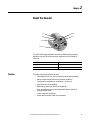
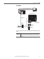
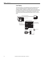
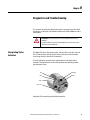
842E-CM Integrated Motion Encoder on EtherNet/IP
User Manual
Important User Information
Solid-state equipment has operational characteristics differing from those of electromechanical equipment.
Safety Guidelines for the Application, Installation and Maintenance of Solid State Controls (publication SGIIN001_-EN-P available from your local Rockwell Automation sales office or online at http://
www.rockwellautomation.com/literature/) describes some important differences between solid-state
equipment and hard-wired electromechanical devices. Because of this difference, and also because of the wide
variety of uses for solid-state equipment, all persons responsible for applying this equipment must satisfy
themselves that each intended application of this equipment is acceptable.
In no event will Rockwell Automation, Inc. be responsible or liable for indirect or consequential damages
resulting from the use or application of this equipment.
The examples and diagrams in this manual are included solely for illustrative purposes. Because of the many
variables and requirements associated with any particular installation, Rockwell Automation, Inc. cannot
assume responsibility or liability for actual use based on the examples and diagrams.
No patent liability is assumed by Rockwell Automation, Inc. with respect to use of information, circuits,
equipment, or software described in this manual.
Reproduction of the contents of this manual, in whole or in part, without written permission of Rockwell
Automation, Inc., is prohibited.
Throughout this manual, when necessary, we use notes to make you aware of safety considerations.
WARNING: Identifies information about practices or circumstances that can cause an explosion in a hazardous environment,
which may lead to personal injury or death, property damage, or economic loss.
ATTENTION: Identifies information about practices or circumstances that can lead to personal injury or death, property
damage, or economic loss. Attentions help you identify a hazard, avoid a hazard, and recognize the consequence.
SHOCK HAZARD: Labels may be on or inside the equipment, for example, a drive or motor, to alert people that dangerous
voltage may be present.
BURN HAZARD: Labels may be on or inside the equipment, for example, a drive or motor, to alert people that surfaces may
reach dangerous temperatures.
IMPORTANT
Identifies information that is critical for successful application and understanding of the product.
Rockwell Automation, Allen-Bradley, CompactLogix, Kinetix, PanelView, POINT I/O, RSLinx, RSLogix, Stratix 5700, and Studio 5000 are trademarks of Rockwell Automation, Inc.
Trademarks not belonging to Rockwell Automation are property of their respective companies.
It is recommended that you save this user manual for future use.
2
Rockwell Automation Publication 842E-UM002A-EN-P - November 2013
Table of Contents
Important User Information . . . . . . . . . . . . . . . . . . . . . . . . . . . . . . . . . . . . 2
Preface
Who Should Use This Manual . . . . . . . . . . . . . . . . . . . . . . . . . . . . . . . . . . .
Purpose of This Manual . . . . . . . . . . . . . . . . . . . . . . . . . . . . . . . . . . . . . . . .
Common Techniques Used in This Manual . . . . . . . . . . . . . . . . . . . . . .
Requirements. . . . . . . . . . . . . . . . . . . . . . . . . . . . . . . . . . . . . . . . . . . . . . . . . .
Components of an Integrated Motion Application . . . . . . . . . . . . . .
Terminology . . . . . . . . . . . . . . . . . . . . . . . . . . . . . . . . . . . . . . . . . . . . . . . . . . .
Related Documentation . . . . . . . . . . . . . . . . . . . . . . . . . . . . . . . . . . . . . . . .
5
5
5
6
6
7
9
Chapter 1
Safety Precautions
Authorized Personnel . . . . . . . . . . . . . . . . . . . . . . . . . . . . . . . . . . . . . . . . .
Correct Use . . . . . . . . . . . . . . . . . . . . . . . . . . . . . . . . . . . . . . . . . . . . . . . . . . .
General Safety Notes and Protective Measures . . . . . . . . . . . . . . . . .
Environmental Protection . . . . . . . . . . . . . . . . . . . . . . . . . . . . . . . . . . . . .
11
12
12
13
Chapter 2
About the Encoder
Features . . . . . . . . . . . . . . . . . . . . . . . . . . . . . . . . . . . . . . . . . . . . . . . . . . . . . .
CIP Sync Overview. . . . . . . . . . . . . . . . . . . . . . . . . . . . . . . . . . . . . . . . .
Typical Configurations . . . . . . . . . . . . . . . . . . . . . . . . . . . . . . . . . . . . . . . .
Star Topology . . . . . . . . . . . . . . . . . . . . . . . . . . . . . . . . . . . . . . . . . . . . .
Linear Topology . . . . . . . . . . . . . . . . . . . . . . . . . . . . . . . . . . . . . . . . . . .
Device Level Ring Topology . . . . . . . . . . . . . . . . . . . . . . . . . . . . . . .
15
16
16
17
18
19
Chapter 3
Installation
Mechanical . . . . . . . . . . . . . . . . . . . . . . . . . . . . . . . . . . . . . . . . . . . . . . . . . . .
Shaft Rotation Direction . . . . . . . . . . . . . . . . . . . . . . . . . . . . . . . . . . .
Mounting with a Solid Shaft . . . . . . . . . . . . . . . . . . . . . . . . . . . . . . .
Mounting with a Hollow Shaft . . . . . . . . . . . . . . . . . . . . . . . . . . . . .
Electrical. . . . . . . . . . . . . . . . . . . . . . . . . . . . . . . . . . . . . . . . . . . . . . . . . . . . . .
Electrical Wiring Instructions . . . . . . . . . . . . . . . . . . . . . . . . . . . . . . .
Pin Assignments. . . . . . . . . . . . . . . . . . . . . . . . . . . . . . . . . . . . . . . . . . .
Functional Specifications . . . . . . . . . . . . . . . . . . . . . . . . . . . . . . . . . .
21
21
21
22
23
23
24
24
Chapter 4
Configuring the Encoder
Configuring the 842E-CM Encoder IP Address . . . . . . . . . . . . . . . . . .
Ethernet Connection . . . . . . . . . . . . . . . . . . . . . . . . . . . . . . . . . . . . . .
842E-CM Encoder Port Configuration . . . . . . . . . . . . . . . . . . . . . .
Setting the IP Address. . . . . . . . . . . . . . . . . . . . . . . . . . . . . . . . . . . . . . . . .
Assigning the Last Octet in an IP Address Scheme of
192.168.1.xxx Using the Network Address Switches. . . . . . . . .
Assigning the IP Address Using BootP/DHCP:. . . . . . . . . . . . . . .
Rockwell Automation Publication 842E-UM002A-EN-P- November 2013
25
25
25
25
26
26
3
Table of Contents
Chapter 5
Example: Setting Up the Hardware. . . . . . . . . . . . . . . . . . . . . . . . . . . . . 29
Configuring the 842E-CM Encoder
Checking the Integration in EtherNet/IP via RSLinx Classic. . . 30
Using the Logix Designer Application
Adding and Configuring the Add-on Profile in RSlogix 5000 . . . .
Adding the Encoder to Your Logix Designer Project. . . . . . . . .
Configuring the Encoder . . . . . . . . . . . . . . . . . . . . . . . . . . . . . . . . . . .
Configuring the Motion Group . . . . . . . . . . . . . . . . . . . . . . . . . . . . .
Configuring Axis Properties . . . . . . . . . . . . . . . . . . . . . . . . . . . . . . . .
Testing the Axis . . . . . . . . . . . . . . . . . . . . . . . . . . . . . . . . . . . . . . . . . . . . . . .
31
31
33
35
36
44
Chapter 6
Diagnostics and Troubleshooting
Interpreting Status Indicators . . . . . . . . . . . . . . . . . . . . . . . . . . . . . . . . . .
Faults and Alarms . . . . . . . . . . . . . . . . . . . . . . . . . . . . . . . . . . . . . . . . . . . . .
Troubleshoot Faults . . . . . . . . . . . . . . . . . . . . . . . . . . . . . . . . . . . . . . .
Encoder Fault and Alarm Subcodes. . . . . . . . . . . . . . . . . . . . . . . . .
842E-CM Exception Behavior . . . . . . . . . . . . . . . . . . . . . . . . . . . . . . .
47
49
49
49
52
Appendix A
Flash Update the 842E-CM Firmware Introduction . . . . . . . . . . . . . . . . . . . . . . . . . . . . . . . . . . . . . . . . . . . . . . . . . . 53
Performing the update . . . . . . . . . . . . . . . . . . . . . . . . . . . . . . . . . . . . . . . . 53
Appendix B
Installing the Add-on Profile
Introduction . . . . . . . . . . . . . . . . . . . . . . . . . . . . . . . . . . . . . . . . . . . . . . . . . . 57
Performing the installation . . . . . . . . . . . . . . . . . . . . . . . . . . . . . . . . . . . . 57
Appendix C
Faults and Alarms Dialog Box
4
Quick View pane . . . . . . . . . . . . . . . . . . . . . . . . . . . . . . . . . . . . . . . . . . . . . . 61
Data Monitor. . . . . . . . . . . . . . . . . . . . . . . . . . . . . . . . . . . . . . . . . . . . . . . . . . 62
Rockwell Automation Publication 842E-UM002A-EN-P - November 2013
Preface
Read this section to familiarize yourself with the rest of the manual. It
provides information concerning:
• Who should use this manual
• The purpose of this manual
• Related documentation
• Conventions used in this manual
Who Should Use This Manual
Use this manual if you are responsible for designing, installing,
programming, or troubleshooting control systems that use the encoder.
You should have a basic understanding of electrical circuitry and
familiarity with relay logic. If you do not, obtain the proper training
before using this product.
Purpose of This Manual
This manual is a reference guide for encoders. It describes the procedures
you use to install, wire, and troubleshoot your encoder. This manual:
• Gives you an overview of the encoders
• Explains how to install and wire your encoder
• Explains how to configure the encoder in the Studio 5000™
environment
Common Techniques Used in
This Manual
The following conventions are used throughout this manual:
• Bulleted lists such as this one provide information, not procedural
steps.
• Numbered lists provide sequential steps or hierarchical
information.
• Italic type is used for emphasis.
Rockwell Automation Publication 842E-UM002A-EN-P - November 2013
5
Preface
Studio 5000 environment version 21 or later, RSLinx® Classic software
version 3.51 or later.
Requirements
Requirements
Components of an Integrated
Motion Application
6
System
Component
Cat. No.
Logix Controller
Platform
1769-L18ERM
1769-L27ERM
1769-L30ERM
1769-L33ERM
1769-L36ERM
CompactLogix™ 5370 controllers with Integrated Motion on the
EtherNet/IP network. Linear, device-level ring (DLR), and star
topology is supported.
1756-EN2T module
1756-EN2TR module
1756-EN3TR module
ControlLogix 1756-L7x controllers with Integrated Motion on
EtherNet/IP networks. Linear, device-level ring (DLR), and star
topology is supported.
Studio 5000™
N/A
Studio 5000 Logix Designer application (version 21.00 or later)
provides support for programming, commissioning, and maintaining
the CompactLogix and ControlLogix controller families.
RSLinx
N/A
Version 3.5 or later
Description
System Overview
System
Component
Cat. No.
Description
Kinetix® 5500
Servo Drives
2198-Hxxx-ERS
200V-class (single-phase or three-phase) and 400V-class (threephase) drives operate in standalone and multi-axis shared AC, shared
DC, shared AC/DC, and shared AC/DC hybrid configurations.
Rotary Servo
Motors
Kinetix VP
Compatible rotary motors include the Kinetix VP (Bulletin VPL) servo
motors. Induction motors with open loop volts/hertz speed control are
also supported.
Cables
Motor cables
Bulletin 2090 single-cable for motor power, feedback, and 24V DC
brake power.
Communication
Ethernet cables are available in standard lengths. Shielded cable is
recommended.
Rockwell Automation Publication 842E-UM002A-EN-P - November 2013
Preface
Terminology
Term
Definition
Axis
An axis is a logical element of a motion control system that exhibits some form of
movement. Axes can be rotary or linear, physical or virtual, controlled or simply
observed.
Boundary Clock
A clock that has multiple PTP ports in a domain and maintains the time scale used in
the domain. It may serve as the source of time, for example, a Master clock, and may
synchronize to another clock, thus being a Slave clock.
CIP
Common Industrial Protocol.
CIP Sync
CIP Sync defines extensions to CIP Common objects and device profiles to support time
synchronization over CIP Networks. CIP Sync is an implementation of the IEEE 1588
standard.
Coordinated System Time
(CST)
A backplane clock propagated between all modules on the ControlLogix backplane.
Coordinated Universal
Time (UTC)
The time standard for civil time, representing time at the Prime Meridian. The time
does not include time zone or daylight savings time offsets. System Time is based on
UTC.
Device Level Ring (DLR)
A DLR network is a single-fault tolerant ring network intended for the interconnection
of automation devices.
Get/Read
A Get/Read involves retrieving an attribute value from the perspective of Controller
side of the interface.
GPS
Global Positioning System, a time source reference.
Grandmaster Clock (GM)
Within a domain, a clock that is the ultimate source of time for clock synchronization
by using the CIP Sync protocol.
Greenwich Mean Time,
(GMT)
Greenwich Mean Time is the mean solar time of the longitude (0°) of the former Royal
Observatory at Greenwich, England, or Greenwich meridian.
UTC replaced GMT as the basis for the main reference time scale or civil time in various
regions on January 1, 1970.
Integrated Motion on the
Ethernet/ IP Network
Defines extensions to CIP Common objects and device profiles to support motion
control over CIP networks.
Integrated Motion on the
Ethernet/ IP network I/O
Connection
The I/O connection is the periodic bidirectional, Class 1, CIP connection between a
controller and a drive that is defined as part of the Integrated Motion on the
EtherNet/IP network standard.
Integrated Motion on the
EtherNet/IP Network Drive
Refers to any drive device that complies with the CIP Motion standard.
Master Clock (M)
In the context of a single CIP Sync communication path, a clock that is the source of
time to which all other clocks on that path synchronize.
The Master clock may not be the Grandmaster. The Master clock is the reference clock
for the local subnet.
Motion
Motion refers to any aspect of the dynamics of an axis. In the context of this document,
it is not limited to servo drives but encompasses all forms of drive based motor control.
Open Loop
Open loop is a method of control where there is no application of feedback to force the
actual motor dynamics to match the commanded dynamics. Examples of open loop
control are stepper drives and variable frequency drives.
Ordinary Clock
A clock that has a single PTP port in a domain and maintains the time scale used in the
domain. It may serve as the source of time, for example, a Master clock, and may
synchronize to another clock, thus being a Slave clock
Precision Time Protocol
(PTP)
A high-precision time synchronization protocol for networked measurement and
control systems, defined by the IEEE 1588 standard.
Rockwell Automation Publication 842E-UM002A-EN-P - November 2013
7
Preface
Term
8
Definition
Quality of Service (QoS)
A function that guarantees a bandwidth relationship between individual applications
or protocols.
Service Data Block
The service data block is a lower priority real-time data block associated with a service
message from the controller that is transferred by an Integrated Motion on the
EtherNet/IP network connection on a periodic basis. Service data includes service
request messages to access attributes, run a drive based motion planner, or perform
various drive diagnostics.
Servo drive
A drive that produces the winding current for a servo motor. The amplifier converts a
low-level control signal into high voltage and current levels in order to produce torque
in the motor.
Set/Write
A Set/Write involves setting an attribute to a specified value from the perspective of
the Controller side of the interface.
Slave (S)
Synchronizes the local clock to the Master time. Synchronizes the local clock frequency
to match the Master reference.
Synchronized
Synchronized is a condition where the local clock value on the drive is locked onto the
master clock of the distributed System Time. When synchronized, the drive and
controller devices may use time stamps associated with an Integrated Motion on the
EtherNet/IP network connection data.
System Time
The absolute time value as defined by CIP Sync in the context of a distributed time
system where all devices have a local clock that is synchronized with a common Master
clock. System Time is a 64-bit integer value in units of nanoseconds or microseconds
with a value of 0 corresponding to an epoch of January 1, 1970.
Time Offset
Time offset is the System Time Offset value associated with the Integrated Motion on
the EtherNet/IP network connection data that is associated with the source device. The
System Time Offset is a 64-bit offset value that is added to a device’s local clock to
generate System Time for that device.
Time Stamp
Time stamp is a system time stamp value associated with the Integrated Motion on
the EtherNet/IP network connection data that conveys the absolute time when the
associated data was captured, or can be also used to determine when associated data
is to be applied.
Transparent Clock
A Transparent Clock improves the accuracy of time synchronization by compensating
for the effect of port to port PTP packet propagation delays.
Variable Frequency Drive
(VFD)
Variable Frequency Drive (VFD) is a class of drive products that seek to control the
speed of a motor, typically an induction motor, through a proportional relationship
between drive output voltage and commanded output frequency. Frequency drives
are, therefore, sometimes referred to as Volts/Hertz drives
TIP Not all servo drives support direct frequency control.
Rockwell Automation Publication 842E-UM002A-EN-P - November 2013
Preface
Related Documentation
The following documents contain additional information concerning
Rockwell Automation products.
Resource
Description
1756-AP016
CIP Sync brochure
1769-UM021
CompactLogix 5370 Controllers User Manual
1770-4.1
Industrial Automation Wiring and Grounding Guidelines
2097-UM002
Kinetix 350 Single-axis EtherNet/IP Servo Drives User Manual
2198-UM001
Kinetix 5500 Servo Drives User Manual
842E-IN002
Installation Instructions 842E-CM EtherNet/IP™ Encoders, Integrated Motion
Encoder on EtherNet/IP
842E-UM001
842E EtherNet/IP Absolute Encoder User Manual
C116-CA001
Sensors Catalog
ENET-RM002
Ethernet Design Considerations Reference Manual
IA-AT003
Integrated Architecture and CIP Sync Configuration Application Technique
M117-CA001
On-Machine Connectivity Catalog
MOTION-RM003
Integrated Motion on the EtherNet/IP Network Reference Manual
MOTION-UM003
Integrated Motion on the EtherNet/IP Network Configuration and Startup
User Manual
IMPORTANT
For best results, grounding the encoder flange is recommended.
Numerous useful publications are available for download at
http://www.rockwellautomation.com/literature. To order paper copies of
technical documentation, contact your local Allen-Bradley distributor or
Rockwell Automation sales representative.
Rockwell Automation Publication 842E-UM002A-EN-P - November 2013
9
Preface
Notes:
10
Rockwell Automation Publication 842E-UM002A-EN-P - November 2013
Chapter
1
Safety Precautions
This chapter deals with your own safety and the safety of the equipment
operators.
Please read this chapter carefully before working with the 842E-CM
Integrated Motion encoder on EtherNet/IP and/or the machine or system
in which the encoder is used. Integrated Motion on Ethernet IP networks
requires use of time synchronization. This is explained in the next
chapter.
Authorized Personnel
ATTENTION: The 842E-CM encoder must only be installed, commissioned, and
serviced by authorized personnel.
ATTENTION: Repairs to the 842E-CM encoder are allowed to be undertaken
only by trained and authorized service personnel from Rockwell Automation.
The following qualifications are necessary for the various tasks:
Activity
Qualification
Mounting
Basic technical training
Knowledge of the current safety regulations in the workplace
Electrical installation and
replacement
Practical electrical training
Knowledge of current electrical safety regulations
Knowledge on the use and operation of devices in the related application (e.g.,
industrial robots, storage, and conveyor technology)
Commissioning, operation, and
configuration
Knowledge on the current safety regulations and the use and operation of devices
typically in Integrated Motion on EtherNet/IP applications
Knowledge of automation systems (e.g., Rockwell ControlLogix controller)
Knowledge of servo control or motion control (e.g., Kinetix for PowerFlex drives)
Knowledge of EtherNet/IP and integrated motion applications
Knowledge of the usage of automation software (e.g., Rockwell Logix Designer)
Rockwell Automation Publication 842E-UM002A-EN-P - November 2013
11
Chapter 1
Safety Precautions
Correct Use
The 842E-CM Integrated Motion encoder is an instrument manufactured
in accordance with recognized industrial regulations, and that meets the
quality requirements as per ISO 9001:2008 as well as those of an
environment management system as per ISO 14001:2009.
An encoder is a device designed to be mounted in a system, and that
cannot be used independently of its intended function. For this reason,
an encoder is not equipped with immediate safety devices.
Considerations for the safety of personnel and systems must be provided
by the constructor of the system, as per statutory regulations.
By design, the encoder can only be operated within an EtherNet/IP
network. It is necessary to comply with the EtherNet/IP specifications and
guidelines for setting up a EtherNet/IP network.
In case of any other usage of, or modifications to the 842E-CM Integrated
Motion encoder, e.g., opening the housing during mounting and
electrical installation, or in case of modifications to the Rockwell
Automation software, any claims against Rockwell Automation under
warranty will be rendered void.
General Safety Notes and
Protective Measures
12
ATTENTION: Please observe the following procedures for correct and safe use
of the 842E-CM Integrated Motion encoder.
ATTENTION: The encoder is to be installed and maintained by trained and
qualified personnel with knowledge of electronics, precision mechanics and
control system programming. You must comply with the pertinent standards
covering the technical safety stipulations.
ATTENTION: All safety regulations are to be met by all persons who are
installing, operating or maintaining the device:
• The operating instructions must always be available and must always be
followed.
• Unqualified personnel are not allowed to be present in the vicinity of the
system during installation.
• The system is to be installed in accordance with all applicable safety
regulations and the mounting instructions.
• All work safety regulations of the applicable countries are to be followed during
installation.
• Failure to follow all applicable health and safety regulations may result in
personal injury or damage to the system.
• The current and voltage sources in the encoder are designed in accordance with
all applicable technical regulations.
Rockwell Automation Publication 842E-UM002A-EN-P - November 2013
Safety Precautions
Chapter 1
Environmental Protection
Please note the following information on disposal.
Assembly
Material
Disposal
Packaging
Cardboard
Waste paper
Shaft
Stainless steel
Scrap metal
Flange
Aluminum
Scrap metal
Housing
Aluminum Die-cast
Scrap metal
Electronic assemblies
Various
Hazardous waste
Rockwell Automation Publication 842E-UM002A-EN-P - November 2013
13
Chapter 1
Safety Precautions
Notes:
14
Rockwell Automation Publication 842E-UM002A-EN-P - November 2013
Chapter
2
About the Encoder
Net
XS (Axis)
Mod
Link 2
Link 1
Screw cover
The 842E-CM Integrated Motion encoder on EtherNet/IP provides a
feedback-only axis for midrange drive applications on EtherNet/IP
networks.
Features
Encoder Version
Bulletin Number
Single-turn
842E-CM-Sxxxx
Multi-turn
842E-CM-Mxxxx
The 842E-CM encoder features include:
• Compatibility with star, linear, and device level ring topologies
• Robust nickel code disk for harsh ambient conditions
• Configurable resolution per revolution: 1 to 262,144
• High precision and availability
• Ball bearing spacing of 30 mm for longer life
• Face mount flange and servo flange/blind hollow shaft and
through hollow shaft
• 18-bit single turn resolution
• 30-bit total resolution multi-turn resolution
Rockwell Automation Publication 842E-UM002A-EN-P - November 2013
15
Chapter 2
About the Encoder
CIP Sync Overview
EtherNet/IP uses CIP Sync and CIP Motion technologies to provide realtime closed-loop motion control with standard Ethernet. This topologyindependent network provides a simplified integration of the entire
control solution on one network.
CIP Sync provides a mechanism to synchronize clocks between
controllers, I/O devices, and other automation products in your
architecture with minimal user intervention. The EtherNet/IP network is
the only network that supports CIP Sync time synchronization.
CIP Sync brings together CIP (Common Industrial Protocol) with the
IEEE 1588-2008 standard for time synchronization. CIP Sync provides
accurate real-time (Real-World Time) or Coordinated Universal Time (UTC)
synchronization of controllers and devices connected over CIP networks
and the ControlLogix backplane. This technology supports highly
distributed applications that require time stamping, sequence of events
recording, distributed motion control, and increased control
coordination.
CIP Sync provides the capabilities to perform the following functions:
• Create sequence of events applications
• System-wide synchronization of time for CIP-based networks
• Integrated Motion on the EtherNet/IP network applications
Typical Configurations
This section explains typical configurations and topologies. The 842E-CM
encoders can be connected in any of three network topologies: star,
linear or device level ring (DLR).
IMPORTANT
16
Rockwell Automation recommends that you use no more than 50 nodes on a
single DLR or linear network. If your application requires more than 50 nodes,
we recommend that you segment the nodes into separate, but linked, DLR or
linear networks.
Rockwell Automation Publication 842E-UM002A-EN-P - November 2013
About the Encoder
Chapter 2
Star Topology
CompactLogix controller programming network
CompactLogix 5370 controller
Logix Designer
application
1 (Front)
2 (Rear)
Kinetix 5500 servo drive system
1585J-M8CBJM-x
Ethernet (shielded) cable
1585J-M8CBJM-OM3
0.3 m (1.0 ft) Ethernet cable
for drive-to-drive connections
1783-BMS
Stratix 5700 ™
switch
PanelView Plus™
display terminal
1734-AENTR POINT I/O
EtherNet/IP adapter
842E-CM encoder
The star structure consists of a number of devices connected to a central
switch.
IMPORTANT
When this topology is used, make the Ethernet connection on the 842E-CM
encoder to the Link 1 connection. The Link 2 Ethernet connection must remain
unused.
Rockwell Automation Publication 842E-UM002A-EN-P - November 2013
17
Chapter 2
About the Encoder
Linear Topology
The linear topology uses the embedded switching capability to form a
daisy-chain style network that has a beginning and an end. Linear
topology simplifies installation and reduces wiring and installation costs,
but a break in the network disconnects all devices downstream from the
break. When this topology is used, both Ethernet connections on the
encoder may be used. For the network connection use Link 1, Link 2, or
both.
CompactLogix controller programming network
CompactLogix 5370 controller
Logix Designer
application
Kinetix 5500 Servo Drive System
1 (Front)
2 (Rear)
1581585J-M8CBJM-OM3
0.3 m (1.0 ft) Ethernet cable
for drive-to-drive connections
1585J-M8CBJM-x
Ethernet (shi elded) cable
PanelView™ Plus
display terminal
18
1734-AENTR POINT I/O™
EtherNet/IP Adapter
Rockwell Automation Publication 842E-UM002A-EN-P - November 2013
842E-CM encoder
About the Encoder
Chapter 2
Device Level Ring Topology
A DLR network is a single-fault-tolerant ring network intended for the
interconnection of automation devices. DLR topology is advantageous as
it can tolerate a a break in the network. If a break is detected, the signals
are sent out in both directions. With this topology, use both the Link 1
and Link 2 Ethernet connections on the 842E-CM encoder.
CompactLogix controller programming network
CompactLogix 5370 controller
Logix Designer
application
1 (Front)
2 (Rear)
1734-AENTR POINT I/O
EtherNet/IP adapter
PanelView Plus
display terminal
1783-ETAP
module
Kinetix 5500 servo drive system
1585J-M8CBJM-OM3
0.3 m (1.0 ft) Ethernet cable
for drive-to-drive connections.
842E-CM encoder
1585D-M4TBJM-x
Ethernet (shielded) cable
Rockwell Automation Publication 842E-UM002A-EN-P - November 2013
19
Chapter 2
About the Encoder
Notes:
20
Rockwell Automation Publication 842E-UM002A-EN-P - November 2013
Chapter
3
Installation
Mechanical
This chapter describes how to install the 842E-CM integrated motion
encoder on EtherNet/IP.
Also refer to the installation sheet provided in the box, publication No.
842E-IN002 (10000481742).
Shaft Rotation Direction
When you view the encoder from the shaft side, the shaft rotation is
clockwise (CW) or counterclockwise (CCW), as shown.
Mounting with a Solid Shaft
1. Be sure to select the proper size flexible coupling clamp to mate to
the encoder shaft, e.g., 845–FC–*–*. See encoder accessories in the
Sensors catalog (C116-CA001).
ATTENTION: Do not rigidly connect the encoder shaft to the machine; this will
cause premature failure of the encoder or machine bearings. Always use a
flexible coupling.
Rockwell Automation Publication 842E-UM002A-EN-P - November 2013
21
Chapter 3
Installation
2. Use the dimension drawings in the installation instructions to
determine the encoder mounting hole locations (see “Related
Documentation” on page 9).
3. Slide the flexible coupling onto the shaft, but do not tighten the set
screws.
4. Mount the encoder and tighten with three size M4 mounting
screws (not supplied).
5. Center the flexible coupling and tighten the set screws.
Mounting with a Hollow Shaft
IMPORTANT
Be sure the mating shaft is chamfered and grease-free.
1. Loosen the screw on the clamping ring with a 2.5-mm star driver.
2. Slide the encoder onto the mating shaft until the flex mount rests
on the machine surface.
ATTENTION: The encoder should slide freely onto the shaft; if not, do not force.
Check the shaft for interferences such as gouges, burrs, rust, or size.
3. Hold encoder firmly and mark the two mounting holes. (If
mounting holes already exist, proceed to Step 6.)
4. Slide the encoder off. Drill and tap the marked holes to accept M4
(or equivalent) screws.
5. Slide the encoder back onto the shaft until the flex mount rests on
the machine surface.
6. Attach the encoder with two M4 (or equivalent) screws.
IMPORTANT
Do not stress the flex mount while tightening the screws.
7. Tighten the clamping ring screw to 1.1 Nm (10 in–lb).
22
Rockwell Automation Publication 842E-UM002A-EN-P - November 2013
Installation
Electrical
Chapter 3
ATTENTION: Switch off the power supply. The machine/system could
unintentionally start while you are connecting the devices.
Ensure that the entire machine/system is disconnected during the electrical
installation.
ATTENTION: Commissioning requires a thorough check by authorized
personnel!
Before you operate a system equipped with the 842E-CM encoder, make sure
that the system is first checked and released by authorized personnel.
Please read more in Chapter 1, Safety Precautions, page 11.
Electrical Wiring Instructions
Three electrical connections are located on the back of the housing.
A 4-pin M12 connector is used for the 24V DC power supply connection.
Two 4-pin M12 connectors are used for the Ethernet connection. The Link
1 connection is used for star networks. For ring networks, use both the
Link 1 and Link 2 connectors. In a linear network, use Link 1, Link 2, or
both connectors.
Link 2 connection
Power connection
XS
Net
Mod
Link 2
Link 1
Link 1 connection
x10
Network
Address
Switches
x100
IMPORTANT
x1
For best results, grounding the encoder flange is recommended.
Also refer to publication 1770-4.1, Industrial Automation Wiring and
Grounding Guidelines, available online at http://
www.rockwellautomation.com/literature/, for additional installation
requirements.
Rockwell Automation Publication 842E-UM002A-EN-P - November 2013
23
Chapter 3
Installation
Pin Assignments
ATTENTION: Wire the voltage supply as shown. Mis-wiring can cause damage
to the encoder.
Voltage supply
Signal
1
Vs
2
3
GND
4
Mating cable
wire color
Function
Brown
Supply voltage 10…30V DC
White
Do not use
Blue
0V DC (ground)
Black
Do not use
2
Blue - 3
GND
1-Brown
Vs
4
Example: Cordset 889D-F4AC-*
Ethernet link connections – Link 1 and Link 2
Pin
Signal
Mating cable
wire color
Function
1
TxD+
White orange
Ethernet
2
RxD+
White green
Ethernet
3
TxD–
Orange
Ethernet
4
RxD–
Green
Ethernet
2
1
3
4
Example: Cordset 1585D-M4TBJM-*
Functional Specifications
24
Operating voltage
10…30V DC
Power consumption
3W
Load current
200 mA
Resolution per revolution
262,144
Revolutions
4,096
Repeat accuracy
±0.002°
Error limit
±0.03°
Code direction
CW or CCW programmable
Interface
EtherNet/IP per IEC 61784-1
IEEE 1588 (IEEE 61588, Precision clock synchronization protocol for
networked measurement and control systems)
Transmission speed
100 MBits/s
Duplex
Full or half
Rockwell Automation Publication 842E-UM002A-EN-P - November 2013
Chapter
4
Configuring the Encoder
Configuring the 842E-CM
Encoder IP Address
This section offers guidance on configuring your Ethernet connection to
the 842E-CM encoder.
Ethernet Connection
Configuration, programming, and diagnosis of the encoder are
performed over the standard 10/100 Mbps Ethernet communication port
by using the Logix Designer application.
842E-CM Encoder Port Configuration
The IP address of the 842E-CM encoder is composed of four octets
separated by three dots to conform to the Class C Subnet structure. Each
octet can be configured with a number between 1 and 254.
There are two methods of changing the current IP address. An address
can be automatically assigned to the encoder (dynamic IP address) when
the encoder is connected to a DHCP (Dynamic Host Configuration
Protocol) enabled server, or you can manually assign a IP address to the
encoder (static IP address). Both methods of configuring the encoder’s IP
address are shown here.
Setting the IP Address
The 842E-CM encoder is shipped with the network address switches set
to 999. You must assign the encoder an IP address using one of the two
methods outlined below.
Set the IP address of the 842E-CM encoder using either one of the
following methods:
1. Use the network address switches (see figure on page 26) on the
encoder to set the last octet of the IP address (192.168.1.xxx).
2. Use the network address switches to enable BootP / DHCP and use
a BootP utility or DHCP server to assign the IP address of the unit on
powerup.
Rockwell Automation Publication 842E-UM002A-EN-P - November 2013
25
Chapter 4
Configuring the Encoder
Assigning the Last Octet in an IP Address Scheme of 192.168.1.xxx
Using the Network Address Switches
1. Set the three network address switches to 888.
2. Cycle power to the encoder.
3. Set the three network address switches to a valid address of
001…254.
4. Cycle power to the encoder.
5. The encoder will power up with the IP address set to 192.168.1.xxx,
where xxx is the position of the three network address switches.
x10
x1
x100
Network address switches set to 123
Assigning the IP Address Using BootP/DHCP:
Verify that the MAC ID of the encoder is in the relationship list in the
BootP Utility or DHCP server before attempting to assign the encoder an
IP address using this procedure.
1. Set the three network address switches to 888.
2. Cycle power to the encoder.
3. Set the three network address switches to 255 or greater (not 888).
4. Cycle power to the encoder
5. The encoder will power up and request an IP address from a BootP/
DHCP server.
6. If the MAC ID of the encoder is in the relationship list, the BootP/
DHCP server will assign the associated IP address to the
corresponding MAC ID.
26
Rockwell Automation Publication 842E-UM002A-EN-P - November 2013
Configuring the Encoder
Chapter 4
Function of Network Address Switch Settings
Setting of network address switches
Function
001-254
Sets last octet of the IP address to the value indicated (xxx
in 192.168.1.xxx)
888
Restores all factory default settings in the encoder and
clearing its IP address and enables DHCP.
Any other setting
Enables last settings (the encoder uses last settings stored
in non-volatile memory).
ATTENTION: Disable DHCP after the new network address is set (see next step).
This prevents unexpected resetting of the network address, which could result
in unintended machine motion or loss of process control.
7. Disable DHCP: click once on the encoder in the relation list to
highlight it. Then click Disable BOOTP/DHCP. This instructs the
842E-CM encoder to retain the IP address at the next power cycle.
Wait for the status message to show that the command was
successfully sent. If the message does not appear, repeat this step.
Rockwell Automation Publication 842E-UM002A-EN-P - November 2013
27
Chapter 4
Configuring the Encoder
Notes:
28
Rockwell Automation Publication 842E-UM002A-EN-P - November 2013
Chapter
5
Configuring the 842E-CM Encoder Using
the Logix Designer Application
This chapter guides you through the steps required to configure the
encoder using Logix Designer software. Note that the modules presented
in this chapter are configured using the Logix Designer application,
version 21.
Example: Setting Up the
Hardware
This example features the CompactLogix L36 ERM processor in slot 0 and
a built-in EtherNet/IP connection. The encoder is connected to a Stratix
5700™ Ethernet switch.
CompactLogix controller programming network
CompactLogix 5370 controller
Logix Designer
application
Kinetix 5500 Servo Drive System
1 (Front)
2 (Rear)
1581585J-M8CBJM-OM3
0.3 m (1.0 ft) Ethernet cable
for drive-to-drive connections
1585J-M8CBJM-x
Ethernet (shi elded) cable
PanelView™ Plus
display terminal
1734-AENTR POINT I/O™
EtherNet/IP Adapter
842E-CM encoder
To work along with this example, configure the system as shown.
• Verify the IP addresses for your programming terminal and 842ECM encoder.
• Verify that you properly connected all wiring and cabling.
Rockwell Automation Publication 842E-UM002A-EN-P - November 2013
29
Chapter 5
Configuring the 842E-CM Encoder Using the Logix Designer Application
• Be sure you configured the communication driver (for example,
AB_ETH-1 or AB-ETHIP-1) in the RSLinx® software.
Checking the Integration in EtherNet/IP via RSLinx Classic
Using the tool RSLinx Classic, check again whether the set IP address is
accurately detected by the control system.
The EDS file (electronic data sheet) contains all the information related to
the parameters as well as the operating modes of the EtherNet/IP
encoder (go to www.rockwellautomation.com/resources/eds/ and search
for "842E-CM." You can register the EDS file using the EDS hardware
installation tool in the Tools menu of RSLinx Classic software.
1. Start RSLinx Classic (as a rule on the Start menu on your PC/
notebook in Rockwell Software, RSLinx, RSLinx Classic).
2. Click on the RSWho button in the program.
3. Then open the path AB_ETHIP1, Ethernet. The encoder can be seen
with its IP address.
IMPORTANT
Before proceeding, install the add-on profile (see Appendix B).
4. Install the add-on profile according to the instructions in
Appendix B.
30
Rockwell Automation Publication 842E-UM002A-EN-P - November 2013
Configuring the 842E-CM Encoder Using the Logix Designer Application
Adding and Configuring
the Add-on Profile in
RSlogix 5000
Chapter 5
After installing and setting up the encoder, use the encoder add-on
profile to add the encoder to the project and configure it.
Adding the Encoder to Your Logix Designer Project
1. Apply power to the controller and open the Logix Designer
application.
2. From the File menu, choose New. The New Controller dialog opens.
3. Select a controller and name it.
4. Click Next.
5. Select the slot your controller is in and configure it.
6. Click Finish.
Rockwell Automation Publication 842E-UM002A-EN-P - November 2013
31
Chapter 5
Configuring the 842E-CM Encoder Using the Logix Designer Application
7. Open the Controller Properties.
8. Click the Date/Time tab.
9. Check Enable Time Synchronization.
This allows the controller to participate in the Logix Time
Synchronization or CIP sync. The controller will also participate in
an election in the Logix system for the best GrandMaster clock.
10. Click OK.
11. If needed, in the I/O Configuration, configure an Ethernet module
(enable time synchronization and motion). This must be a CIP Sync
capable Ethernet bridge, such as the 1756-EN2T, EN2TR, or EN3TR.
12. Right-click on the Ethernet port or Ethernet module of the controller
and select New Module.
13. Select the desired 842E-CM encoder (single turn or multi-turn) and
click Create.
32
Rockwell Automation Publication 842E-UM002A-EN-P - November 2013
Configuring the 842E-CM Encoder Using the Logix Designer Application
Chapter 5
14. Close the Select Module Type dialog box. The New Module dialog
box opens.
Configuring the Encoder
1. Configure the new encoder module.
a. Type the encoder Name.
b. Click an Ethernet Address option. In this example, the Private
Network address is selected.
c. Enter the address of the encoder.
2. Click the Associated Axes tab.
3. Click New Axis. The New Tag dialog box opens.
Rockwell Automation Publication 842E-UM002A-EN-P - November 2013
33
Chapter 5
Configuring the 842E-CM Encoder Using the Logix Designer Application
4. Name the new tag.
5. The data type will be AXIS_CIP_DRIVE.
6. Click Create. The new axis (Master_Fdbk) appears under Motion
Groups>Ungrouped Axes in the Controller Organizer and is
assigned as Axis 1.
7. Click Apply.
34
Rockwell Automation Publication 842E-UM002A-EN-P - November 2013
Configuring the 842E-CM Encoder Using the Logix Designer Application
Chapter 5
Configuring the Motion Group
Follow these steps to configure the motion group.
1. Right-click Motion Groups in the Controller Organizer and choose
New Motion Group. The New Tag dialog box opens.
2. Type the new motion group Name.
3. Click Create. The new motion group appears under the Motion
Groups folder.
4. Right-click the new motion group and choose Properties. The
Motion Group Properties dialog box opens.
5. Click the Axis Assignment tab and move your axes (created earlier)
from Unassigned to Assigned.
Rockwell Automation Publication 842E-UM002A-EN-P - November 2013
35
Chapter 5
Configuring the 842E-CM Encoder Using the Logix Designer Application
6. Click the Attribute tab and edit the default values as appropriate for
your application. For this encoder, a coarse update rate from 4…32
ms is supported. If you set the coarse update rate outside that
range, you will receive an error message.
7. Click OK.
Configuring Axis Properties
Follow these steps to configure axis properties.
1. Right-click the axis in the Controller Organizer and choose
Properties.
2. Select the General Category.
3. From the General pull-down menus, change configuration settings
as needed for your application.
4. From the Associated Module >Module pull-down menu, choose
your encoder.
36
Rockwell Automation Publication 842E-UM002A-EN-P - November 2013
Configuring the 842E-CM Encoder Using the Logix Designer Application
Chapter 5
5. Click Apply.
6. Select the Master Feedback category; the Master Feedback
specification dialog box opens.
7. Select Type: Hiperface. This is currently the only choice for Type.
8. Set the resolution for the encoder; set the number of turns as
appropriate to your encoder. The effective resolution should be
displayed. The configuration for multi-turn is shown below. For
single turn, Turns should be 1.
9. Click Apply.
10. Select the Scaling category and edit the default values as
appropriate to your application. If you make changes, click Apply.
Rockwell Automation Publication 842E-UM002A-EN-P - November 2013
37
Chapter 5
Configuring the 842E-CM Encoder Using the Logix Designer Application
11. Select the Homing category. The default values are Passive Mode
and Sequence: Immediate.
12. Enter the desired value for position. This will be the home position.
13. Select Actions. Here you can select the fault exception behavior for
your device and the Soft Travel Limits. Shutdown is currently the
only available exception behavior.
38
Rockwell Automation Publication 842E-UM002A-EN-P - November 2013
Configuring the 842E-CM Encoder Using the Logix Designer Application
Chapter 5
14. Select Drive Parameters. Check the boxes for desired real-time data.
IMPORTANT
Firmware revision 1.002 supports the Velocity and Acceleration parameters.
Rockwell Automation Publication 842E-UM002A-EN-P - November 2013
39
Chapter 5
Configuring the 842E-CM Encoder Using the Logix Designer Application
15. Select the Parameter List category. Enter the necessary changes
based on your application requirements.
NOTE: Velocity Filter Bandwidth, Acceleration Filter Bandwidth, Velocity
Threshold and Velocity Standstill Window cannot be set from the
Parameter List. To set these parameters, use the following message
instructions.
This procedure sends a Logix message to set the following parameters.
IMPORTANT
These new values are set to volatile memory and are not retained upon a
power cycle. Follow the sample below or use a similar method to write the
values to the encoder memory after a loss of connection to the device.
a. Velocity Threshold: This parameter defines a minimum
absolute velocity. If the magnitude of the velocity feedback
signal is less than this value, the Velocity Threshold status bit is
set.
40
Rockwell Automation Publication 842E-UM002A-EN-P - November 2013
Configuring the 842E-CM Encoder Using the Logix Designer Application
Chapter 5
b. Set the values in the Message Configuration dialog box as
shown.
NOTE: The Source Element must be a REAL data type, and its default
value is 6000 rps.
c. Click the Communication tab and browse to the encoder tag; in
this case, “encoder” as shown.
The same procedure is required for the following parameters.
Rockwell Automation Publication 842E-UM002A-EN-P - November 2013
41
Chapter 5
Configuring the 842E-CM Encoder Using the Logix Designer Application
Velocity Standstill Window: This value establishes a window around
zero speed. When the velocity feedback signal is within this window, the
Velocity Standstill status bit is set. If the Velocity Feedback signal falls
outside the defined window, the Velocity Standstill status bit is cleared.
The source element must be a REAL data type; its default value is 3.0 rps.
Velocity Filter Bandwidth: (equivalent to Feedback 1 Velocity Filter
Bandwidth in Hz) This parameter controls the bandwidth of the low pass
filter applied to the raw velocity signal from Feedback.
Default value: 100 (recommended bandwidth 1 to 1000Hz), Attribute
disabled: 0
The source element must be a REAL data type.
42
Rockwell Automation Publication 842E-UM002A-EN-P - November 2013
Configuring the 842E-CM Encoder Using the Logix Designer Application
Chapter 5
Acceleration Filter Bandwidth: (equivalent to Feedback 1 Acceleration
Filter Bandwidth in Hz) This value controls the bandwidth of the low pass
filter applied to the raw acceleration signal from Feedback.
Default value: 100 (recommended bandwidth 1 to 1000Hz), Attribute
disabled: 0
NOTE: To verify, you can issue a Service Type “Get Attribute Single”
message using the same Class, Instance and Attribute data, as well as add
a destination element to ensure that the correct value was successfully
written into the encoder. Refer to the following example to verify the
acceleration low pass filter value.
Rockwell Automation Publication 842E-UM002A-EN-P - November 2013
43
Chapter 5
Configuring the 842E-CM Encoder Using the Logix Designer Application
Sample code is available. Visit the Rockwell Automation Sample Code
Library, and search for “CIP motion encoder” or “842E-CM.”
To download the sample code with the above information, select
Downloads on the following page:
http://www.rockwellautomation.com/rockwellautomation/support/
Testing the Axis
After you have configured the 842E-CM encoder and the Logix5000
controller, applied power, and are on line with the controller, follow the
steps below to test the axis.
IMPORTANT
Before proceeding with testing the axis, verify that the MOD and NET status
indicators are green.
1. Verify that the encoder is on line with the Logix5000 controller and
the encoder does not exhibit any faults.
2. In your Logix project, select Controller Tags.
3. Select the Monitor Tags tab and scroll to your encoder data.
4. Move the encoder shaft and verify that the position values change.
5. Verify that the encoder polarity is correct.
• If the polarity is correct, axis testing is complete.
44
Rockwell Automation Publication 842E-UM002A-EN-P - November 2013
Configuring the 842E-CM Encoder Using the Logix Designer Application
Chapter 5
• If you need to change the polarity, select Axis Properties > Polarity.
Click the Inverted radio button.
Rockwell Automation Publication 842E-UM002A-EN-P - November 2013
45
Chapter 5
Configuring the 842E-CM Encoder Using the Logix Designer Application
Notes:
46
Rockwell Automation Publication 842E-UM002A-EN-P - November 2013
Chapter
6
Diagnostics and Troubleshooting
This chapter describes the diagnostic process to correct and clear fault
conditions on the 842E-CM encoder. Refer to MOTION-UM003 for more
information.
ATTENTION: Cease operation if the cause of the malfunction has not been
identified!
Stop the machine if you cannot clearly identify the error and/or if you cannot
safely eliminate the malfunction.
Interpreting Status
Indicators
The Mod LED shows the device status, the Net LED shows the status of
the CIP connection, and the XS LED shows the status of the internal
measuring device in the 842E-CM encoder.
Five LED indicators provide status information on the back of the
encoder. The figure below shows their location; the following tables
describe their status.
Net
Mod
XS (Axis)
Link 2
Link 1
Screw cover
Read the LEDs according to the following tables.
Rockwell Automation Publication 842E-UM002A-EN-P - November 2013
47
Chapter 6
Diagnostics and Troubleshooting
Net LED
Description
OFF
No power/IP connection
Green
Connected
Green flashing
No connection
Red
Major fault
Red flashing
Minor fault / Duplicate IP
Mod LED
Description
OFF
No power
Green
Running
Green flashing
Standby
Red
Major fault
Red flashing
Minor fault
Green/red flashing
Self-test
XS (Axis) LED
Description
OFF
No power
Green
Running
Green flashing
Standby
Red flashing
Minor fault or Firmware updating
Amber
Major fault
Amber flashing
Self-test at power-on
Ethernet Link LEDs Link 1 and 2
The Ethernet link LEDs, Link 1 and Link 2, display the status of the physical
connection on the Ethernet interface.
48
Link 1 and Link 2 LEDs
Description
OFF
No power/IP address
Green
LINK
Green flashing
Port activity
Amber
Port disabled
Amber flashing
Collision
Rockwell Automation Publication 842E-UM002A-EN-P - November 2013
Diagnostics and Troubleshooting
Faults and Alarms
Chapter 6
There are four ways to identify and view faults and alarms:
• Fault and Alarm log
• Quick View pane
• Tag Monitor, see the individual fault-related attributes
• Status Indicators
For more information, see MOTION-UM003 or Appendix C.
Troubleshoot Faults
The controller may exhibit the following types of motion faults.
Type
Description
Example
Instruction error
Caused by a motion instruction:
• Instruction errors do not impact controller operation.
• Look at the error code in the motion control tag to see
why an instruction has an error.
• Fix instruction errors to optimize execution time and
make sure that your code is accurate.
See Error Codes (ERR) for Motion Instructions, publication
MOTION-RM002.
An instruction with a parameter out
of range.
Fault
Caused by an anomaly with the servo loop:
• You choose whether motion faults give the controller
major faults.
• Can shutdown the controller if you do not correct the
fault condition.
• Loss of feedback.
• Actual position exceeding an
overtravel limit.
Table 1 - Encoder FLT Fault Code
Exception code on
display
Exception text
Problem
Possible solutions
FLT S47 – FDBK DEVICE
FAILURE
Feedback Device
Failure
The feedback device
has detected an
internal error.
• Check feedback cable connectors
• Cycle control power
• Replace encoder if fault continues
Encoder Fault and Alarm Subcodes
The following table shows the sensor encoder fault and alarm subcodes
communicated through the Cyclic Data Channel of the controller.
Subcodes will appear in the Axis Fault Log.
Rockwell Automation Publication 842E-UM002A-EN-P - November 2013
49
Chapter 6
Diagnostics and Troubleshooting
Position
AxisFaultSubCode
Description
Hex value
Decimal
value
1
Over temperature sensor
Temperature value of the sensor is out of
range
0x1E
30
2
Light control reserve
LED current is incorrect
0x1D
0x2C
29
44
3
Frequency exceeded
Speed too high
(limit exceeded)
0x1F
31
4
Position error
Amplitude error Single
0x01
1
5
Position error
Amplitude error Multi
0x21
33
6
Position error
Vector length single
Vector length (Sin² + cos²)
0x1C
28
7
Position error
Vector length multi
Vector length (Sin² + cos²)
0x23
35
8
Position error
LY Digital Random Error and LY MFP5
Error
(single position)
0x20
0x2A
32
42
9
Position error
Position Multi turn error,
synchronization
(MA-Single, Init)
0x22
0x2B
34
43
10
Position error
Position Multi turn error, internal
Interface
0x25
37
11
Position error
SSI Failure - internal communication
interface
0xFF
255
12
Startup error
Startup error
0x18
0x02
24
2
13
Position or Memory error
Memory or EEPROM CheckSum error
0x06
6
14
Memory error
Memory or EEPROM
I2C error
0x05
5
15
Diagnostic error
This Flag is set if the encoder detects a
diagnostic error.
0x2F
47
Table 2 - Encoder Fault Code Summary
50
Fault code type
Description
NODE FLTxx
Exceptions that prevent normal operation of the encoder.
NODE ALARM xx
Exceptions that prevent normal operation of the encoder, but do not result in any
action other than reporting the alarm to the controller.
INHIBIT Mxx
Exceptions that prevent normal operation and indicate whenever the encoder is
active.
Rockwell Automation Publication 842E-UM002A-EN-P - November 2013
Diagnostics and Troubleshooting
Chapter 6
Table 3 - Node FLT Fault Codes
Exception code
on display
Exception text
Problem
Possible solutions
NODE FLT 01 –
LATE CTRL UPDATE
Control Connection
Update Fault
Several consecutive
updates from the controller
have been lost.
• Remove unnecessary network devices
from the motion network
• Change network topology so that
fewer devices share common paths
• Use high performance network
equipment
• Use shielded cables
• Separate signal wiring from power
wiring
NODE FLT 02 –
PROC WATCHDOG
Processor Watchdog
Fault
The processor on the power
board or control board
failed to update in a certain
amount of time.
• Cycle control power
• Update the encoder firmware
• Return encoder for repair if fault
continues
NODE FLT 05 –
CLOCK SKEW FLT
Clock Skew Fault
The controller time and the
encoder's system time are
not the same.
• Cycle control power
• Check controller and Ethernet switch
operation
NODE FLT 06 –
LOST CTRL CONN
Lost Controller
Connection Fault
Communication with the
controller has been lost.
Check Ethernet connection
Check controller and Ethernet switch
operation
NODE FLT 09 –
DUPLICATE IP
ADDRESS
Duplicate IP Address
Fault
Another device shares the
same IP address on the
network.
Select an IP address currently unused on
the network.
Table 4 - NODE ALARM Fault Codes
Exception code
on display
Exception text
Problem
Possible solutions
NODE ALARM 01 –
LATE CTRL UPDATE
Control Connection
Update Alarm
Updates from the
controller have been late.
• Remove unnecessary network devices
from the motion network
• Change network topology so that
fewer devices share common paths
• Use high performance network
equipment
• Use shielded cables
• Separate signal wiring from power
wiring
Rockwell Automation Publication 842E-UM002A-EN-P - November 2013
51
Chapter 6
Diagnostics and Troubleshooting
842E-CM Exception Behavior
For 842E-CM encoders, shutdown is currently the only selectable
exception behavior in the Logix Designer application from the Axis
Properties dialog box, in the Actions category.
Table 5 - Exception Action Definition
Exception action
Definition
Shutdown
When the exception occurs, the encoder brings the motor to a stop by using
the stopping action defined by the encoder (as in Stop encoder) and the
power module is disabled. An explicit Shutdown Reset is required to restore
the encoder to operation
Only selected encoder exceptions are configurable. In the fault behavior
tables, the controlling attribute is given for programmable fault actions.
See the Logix Designer Axis Properties screen, Actions category.
Table 6 - Encoder Behavior, FLT Sxx Fault Codes
52
Exception fault
code
Exception text
FLT S47 – FDBK
DEVICE FAILURE
Feedback device
failure
Fault action
Ignore
Rockwell Automation Publication 842E-UM002A-EN-P - November 2013
Alarm
Minor fault
Major fault
X
Appendix
A
Flash Update the 842E-CM Firmware
Introduction
This appendix explains how to flash update new firmware for the 842ECM product. To download the latest firmware for the 842E-CM, copy the
following link in your Internet browser, and click on the Go icon:
http://www.rockwellautomation.com/rockwellautomation/support/
firmware/overview.page
IMPORTANT
Check the 842E-CM encoder label before flashing
firmware. If the label indicates FW:1.002 (or higher), use
the following procedure to update the firmware.
If the firmware version is not stated on the label, visit the Rockwell
Knowledgebase and search for “842E-CM Firmware Update Procedure” to
look up the appropriate firmware update method.
Performing the Update
If firmware revision 1.002 (or higher) is stated on the encoder label,
proceed to update the firmware.
1. First, verify successful RSLinx Classic communications with the
842E-CM encoder via EtherNet/IP using RSWho Ethernet or
EtherNet/IP driver.
Rockwell Automation Publication 842E-UM002A-EN-P - November 2013
53
Appendix A
Flash Update the 842E-CM Firmware
2. Start ControlFLASH and select Network or Local network.
3. Click Next.
4. Select the catalog number of the 842E-CM encoder whose
firmware you wish to upgrade, then click Next.
54
Rockwell Automation Publication 842E-UM002A-EN-P - November 2013
Flash Update the 842E-CM Firmware
Appendix A
5. Select the controller in the browse window, and click OK.
6. Click Next to continue, and verify the revisions. Click Finish and Yes
to initiate the upgrade.
Rockwell Automation Publication 842E-UM002A-EN-P - November 2013
55
Appendix A
Flash Update the 842E-CM Firmware
7. The next screen shows the download progress.
8. If you see an error message instead, click OK to clear the window
and power cycle the encoder before trying again.
9. Upon successful completion of the flash update, you see an Update
complete status screen. Click OK to complete the update.
Upon s
56
Rockwell Automation Publication 842E-UM002A-EN-P - November 2013
Appendix
B
Installing the Add-on Profile
Introduction
This appendix shows how to install the add-on profile (AOP) of the
encoder with the RSLogix 5000 program. Add-on profiles are files that
users add to their Rockwell Automation library. These files contain the
pertinent information for configuring a device that will be added to the
Rockwell Automation network.
The add-on profile simplifies the configuration of devices because it
presents the necessary fields in an organized fashion, which allows users
to set up and configure their systems in a quick and efficient manner.
The add-on profile is a folder containing numerous files for the device. It
comes as an installation package.
Performing the installation
Install the add-on profile following the on-screen instructions.
1. In the file explorer, locate the directory where the installation files
were extracted.
2. Click MPSetup.exe.
3. Extract the zip file to a local directory on your computer.
4. Double-click on MPSetup.exe to begin the installation.
Rockwell Automation Publication 842E-UM002A-EN-P - November 2013
57
Appendix B
Installing the Add-on Profile
5. At the welcome screen, click on Next.
6. Click the radio button to accept the licensing terms, then click Next.
58
Rockwell Automation Publication 842E-UM002A-EN-P - November 2013
Installing the Add-on Profile
Appendix B
7. Click the Install radio button, then click Next.
8. Click Install to begin the installation.
Rockwell Automation Publication 842E-UM002A-EN-P - November 2013
59
Appendix B
Installing the Add-on Profile
9. Click Next to install the add-on profile files.
10. Click Finish to complete the installation.
60
Rockwell Automation Publication 842E-UM002A-EN-P - November 2013
Appendix
C
Faults and Alarms Dialog Box
The Faults and Alarms dialog box displays the current status of faults and
alarms in the controller for an axis. The display is read-only except for the
ability to clear logs. Fault and alarm entries are displayed only when you
are online with a controller. See also Chapter 6, “Diagnostics and
Troubleshooting.”
Quick View pane
The Quick View pane gives you a quick summary of faults and alarms
related to the axis you select in the Controller Organizer. The information
includes the type of axis, description, axis state, faults and alarms.
Rockwell Automation Publication 842E-UM002A-EN-P - November 2013
61
Appendix C Faults and Alarms Dialog Box
Data Monitor
62
The Data Monitor is where you can read and write the values assigned to
specific tags, both online and offline.
Rockwell Automation Publication 842E-UM002A-EN-P - November 2013
Rockwell Automation Support
Rockwell Automation provides technical information on the Web to assist you in using its products.
At http://www.rockwellautomation.com/support, you can find technical manuals, technical and application
notes, sample code and links to software service packs, and a MySupport feature that you can customize to
make the best use of these tools. You can also visit our Knowledgebase at http://
www.rockwellautomation.com/knowledgebase for FAQs, technical information, support chat and forums,
software updates, and to sign up for product notification updates.
For an additional level of technical phone support for installation, configuration, and troubleshooting, we offer
TechConnectSM support programs. For more information, contact your local distributor or Rockwell Automation
representative, or visit http://www.rockwellautomation.com/support/.
Installation Assistance
If you experience a problem within the first 24 hours of installation, review the information that is contained in
this manual. You can contact Customer Support for initial help in getting your product up and running.
United States or Canada
1.440.646.3434
Outside United States or Canada
Use the Worldwide Locator at http://www.rockwellautomation.com/support/americas/phone_en.html, or contact your local Rockwell
Automation representative.
New Product Satisfaction Return
Rockwell Automation tests all of its products to ensure that they are fully operational when shipped from the
manufacturing facility. However, if your product is not functioning and needs to be returned, follow these
procedures.
United States
Contact your distributor. You must provide a Customer Support case number (call the phone number above to obtain one) to your distributor to
complete the return process.
Outside United States
Please contact your local Rockwell Automation representative for the return procedure.
www.rockwel lautomation.com
Power, Control and Information Solutions Headquarters
Americas: Rockwell Automation, 1201 South Second Street, Milwaukee, WI 53204-2496 USA, Tel: (1) 414.382.2000, Fax: (1) 414.382.4444
Europe/Middle East/Africa: Rockwell Automation NV, Pegasus Park, De Kleetlaan 12a, 1831 Diegem, Belgium, Tel: (32) 2 663 0600, Fax: (32) 2 663 0640
Asia Pacific: Rockwell Automation, Level 14, Core F, Cyberport 3, 100 Cyberport Road, Hong Kong, Tel: (852) 2887 4788, Fax: (852) 2508 1846
Publication 842E-UM002A-EN-P– November 2013
Copyright © 2013 Rockwell Automation, Inc. All rights reserved.