1
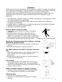
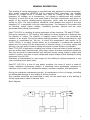
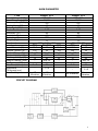
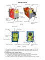
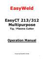
EasyWeld
EasyCT 213/312
Multipurpose
Tig / Plasma Cutter
Operation Manual
Hong Kong EasyWeld Limited
1
Introduction
The EasyCT series of Welders is a revolutionary new approach to Welding
technology. Easyweld introduced a more efficient way to manufacture top
quality machines while keeping the cost of operation and repairs lower. This was
accomplished using several new approaches to the mainstream technology. One
of these methods is our proprietary plug-and-play main circuit boards which
allow ease of repair, reducing the downtime to only hours rather than days,
while also reducing repair costs averaging less than $75! The EasyCT 213/312
uses special safety redundant circuitry with built in auto-protection and self
adjusting circuitry to keep your machine running in a safe threshold. This helps
protect your machine from over-voltage, power spikes, burn-outs and shorting.
Warranty
The machine is insured against damage upon shipping. If you machine is
damaged in any way when you receive it, you must retain all shipping materials
and packing. Call our customer service department and report the damage
immediately.
There is a 1 year warranty on all internal electronic parts. The torch, power cord,
clamps, air regulator, hoses, case & paint and consumables and cables are not
covered under warranty. You must use dry gas in your machine and keep it
indoors away from rain and moisture.
This machine is designed to operate from 200-240vac at 50-60Hz Only.
Operating outside of limits will void warranty.
Warranty coverage covers repair or replacement of damaged machine or
damaged circuit board. Warranty does not cover shipping from the customer but
does cover return shipping within the Cont. United States. If you are going to
return a machine to us for repairs, it must be well packed and insured.
Customers who own machines that require warranty coverage should contact
our warranty department by email at [email protected] to obtain a return
authorization code.
Customers who own an out-of-warranty machine that require repairs should
contact us for an estimate.
2
CONTENTS
- Warning
4
- General Description
5
- Main Parameter
6
- Installation
7
- Operation
9
- Caution
9
- Maintenance
10
- Troubleshooting
10
3
WARNING
Welding and cutting is dangerous to the operator, people in or near the working
area, and the surrounding, if the equipment is not correctly operated. Therefore,
the performance of welding/cutting must only be under the strict and
comprehensive observance of all relevant safety regulations. Please read and
understand this instruction manual carefully before the installation and
operation.
• The switching of function modes is possibly damaging to the equipment, while
the welding operation is performed.
• Do disconnect the electrode-holder cable with the equipment, before the
performance of welding.
• A safety switch is necessary to prevent the equipment from electric-leakage.
• Welding tools should be of high quality.
• Operators should be qualified.
Electric Shock: It may be fatal
• connect the earth cable according to standard
regulation.
• Avoid all contact with live components of the
welding circuit, electrodes and wires with bare
hands. It is necessary for the operator to wear dry
welding gloves while he performs the welding task.
• The operator should keep the working piece
insulating from himself/herself.
Smoke and Gas generated wile welding or cutting:
harmful to people’s health.
• Avoid of breathing the smoke and gas of welding or
cutting.
• Keep the working area in good ventilation.
Arc light-emission: harmful to people’s eyes and
skin
• Wear the welding helmet, anti-radiation glass and
work clothes while the welding operation is
performed.
• Measures also should be taken to protect people in
or near the working area.
Fire hazard
• The welding splash may cause fire, thus remove
flammable material away from the working place.
• Have a fire extinguisher nearby, and have a train fire
person ready to use it.
Noise: Possibly harmful to peoples’ hearing.
• Surface noise is generated while welding/cutting,
the hearing aids is necessary in some cases.
Machine Fault:
• Consult this instruction manual.
• Contact your local dealer or supplier for further
advice.
4
GENERAL DESCRIPTION
This welding & cutting equipment is manufactured with advanced inverter technology.
With power component MOSFETS and by adopting PWM technology, the inverter
converts DC voltage which is rectified from input AC voltage to the high 100KHz
frequency AC voltage; as a consequence, the voltage is transformed and rectified.
Therefore, it result the much more small-sized of the main transformer and lighter in
weight of the inverter welding/cutting equipment, which rates the performance of
cutting by 30%. The high frequency oscillation, which enables the output of the high
frequency DC, is employed in the arc-starting system. The features of this product are
as following: stable output, reliable, completely portable, efficient and low noise
generated while cutting is performed.
EasyCT 213/312 is a welding & cutting equipment of two functions: TIG and CUTTING.
During the operation of TIG welding, this welding & cutting equipment is featured with
the stability of output. The stability of welding current output is not frustrated by
variation of arc length. During the plasma cutting operation, being compressed by high
pressure of compressed air, the arc, of which the temperature rises rapidly up to
10000-15000t, is of highly ionized status, as a consequent, it produces the powerful
plasma arc for cutting. By the employment of plasma cutting, it is energy saving and
efficient; the high speed of metal cutting and smooth incised surface is accessible.
EasyCT 213/312 is applicable in welding and cutting of various kinds of metal materials,
such as carbon steel, stainless steel, alloy steel, copper and other nonferrous metals etc.
Also they are small in measurement, high efficient, energy saving, stable in output and
reliable in quality; the ratio of input voltage and output voltage of this welding & cutting
equipment is up to 85%.
Guarantee of maintenance for main engine of this welding & cutting equipment is one
year, excluding other spare parts.
EasyCUT 213/312 is a kind of new plastic products, the cover of which is made of
impact resistance engineering plastics. It possesses more advantages compared to
machines of iron case, such as beautiful design, excellent insulation, and waterproof.
During the guarantee maintenance period, all maintenance is free of charge, excluding
the deliberated damage to this welding & cutting machine.
Only qualified technician are authorized to carry out the repair task of this welding &
cutting equipment in case of machine fault.
Block Diagram
5
MAIN PARAMETER
TYPE
Input Voltage (VAC)
Input Frequency (Hz)
Consumption (KVA)
No-load Loss (W)
Duty Cycle (%)
Power Factor
Efficiency (%)
Insulation Class
Protection Class
Weight (Kg)
Size(mm)
Input Current (A)
Output Current (A)
Current Range (A)
No load Voltage (V)
Working Voltage (V)
Nozzle Internal (mm)
Air Pressure (MPa)
Gas Flow (L/min)
Applicable
Thickness(mm)
Arc-Starting
EasyCT 312
220±15%
50/60
3.5
40
60
0.93
85
B
1P21
8
395 × 163 × 290
TIG
PLASMA
MMA
10.2
16
15.6
130
30
120
5~130
15~30
10~120
60
230
60
15
92
25
Dia.
10
0.4
2~5
80
1~8
HF
Vibration
HF
Vibration
-
EasyCT 213
220±15%
50/60
4.2
40
60
0.93
85
B
1P21
8
390x280x390
TIG
PLASMA
10.2
19
125
30
10~125
10~30
55
220
15
92
Dia. 10
0.4
2~5
80
HF Vibration
1~8
HF
Vibration
CIRCUIT DIAGRAM
6
INSTALLATION
Main Current
Power Switch
Pilot Lamp
Power Lamp
Compress Air Gas
Inlet
Function
Switch
Ground
Connection
Electrode
Holder
Connection
Argon Gas Inlet
Torch 2-pin Socket
Compress Air Gas
Regulator
Torch Connection
CT-312
Main Current
Pilot Lamp
Power Lamp
Power Switch
Function
Switch
Torch Connection
Argon Gas Inlet
Torch 2-pin Socket
Ground Connection
CT-213
Compress Air Gas
Regulator
Compress Air Gas
Inlet
1. Connection of the Input Cables
Connect this welding & cutting equipment with power supply of 220V AC.
Connect the earth terminal with the earth cable of minimum diameter of
2.5mm2.
2. Connection of the Output Cables
2a. Install welding/cutting torch according to the drawing.
2b. Connect the one-knob connector and air plug to the corresponding
connector on the panel board. Then fasten the screw.
2c. Plug the air plug of the back cable to in the clockwise direction. Connect
7
earth clamp with work piece.
2d. The electrode holder cable should normally be connected to the positive
terminal, while the work piece should be connected to the negative
terminal.
3. Power Supply Switch
In case that power switch is on, built-in fan start work and current meter
displays the current value.
4. Function Switch
Function switch enables the option among MMA, TIG and CUT according to
practical welding task requirement.
4a. TIG Welding Function
Connect with gas supply: Connect the argon hose to the copper nozzle of
the back panel. The gas supply system includes the gas bottle, air
regulator and gas hose. The connection of parts of gas system should be
firm to prevent the gas leakage.
Install the argon torch according to the drawing. Connect the copper
screw on the cutting torch to the output terminal of the one-knob of the
front panel, and fasten it toward clockwise direction to avoid gas leaking.
Connect the plug of the closed circuit to the “+” socket on the panel board;
Connect the earth clamp with the work piece.
4b .PLASMA Cutting Function
Connect the gas hose with the terminal “IN” of regulator and connect the
“OUT” terminals of regulator with the copper tub. The pressure and
volume of output gas should be sufficient.
Connect the copper nut of the cutting torch to the knob of the panel board;
plug with the plug of the panel board.
Connect the fast plug of earth cable with front panel of this welding &
cutting equipment.
4b .MMA Welding Function (CT-312)
There are two modes of connection according to the specification of
welding electrode.
•Straight polarity: electrode holder to “-”, work piece to “+”;
•Reverse polarity: electrode holder to “+”, work piece to “-”
5. Welding Current Output Setting
According to practical demand, set the parameters of current output by the
operation of “ARC” “TIG”, or “CUT”
INSTALLATION OF THE GAS REGULATOR:
1) Seal the connection of the copper gas hose and the “IN” terminal and ‘OUT”
terminals.
2) Connect the regulator seal to the installation place of the regulator.
3) Fix the rack with screw to the place of the air regulator at the back of the
machine.
4) Remove the rubber nut. Connect the regulator with the track.
5) Release the gas valve, modulate the pressure of gas to stipulated pressure,
and press the button.
6) The gas pressure is 4 times of normal atmospheric pressure.
7) In case that the water-filtering bottle is full with water, remove the water.
Please note that:
--Please choose the Argon gas supply respectively for TIG welding and
compressed air supply of higher than 4 bars for plasma cutting.
--The duty cycle for cutting of the machine is 60%.
8
OPERATION
1. TIG Welding Function
1) While this welding & cutting equipment is operated, power supply indicator
is on, and the built-in fan is functioning.
2) Opt the TIG welding function mode.
3) Press the gas-releasing button, and modulate the volume of gas output to
the required value.
4) Press the button of welding torch, and the electromagnetic valve functions.
The sound of electricity releasing is audible and there is gas out from
welding torch.
Please note that: before the initial welding operation, press the button of
welding torch for several seconds in order to remove the gas inside the
gas tub, and the welding operation is accessible. There is gas output within
a few seconds after the welding operation that is special design to protect
the welding point before it is cooling down. Therefore, after the extinction
of arc, maintain the welding position to abstract the heat produced during
the welding operation.
5) The welding current output is adjustable, according to the thickness of
welding material and required craftsmanship.
6) Maintain the distance of 1-4mm between the tungsten electrode and the
work piece. Press the button of welding torch. HF electricity releasing
between the welding electrode and the work piece occurs; after the arc
starting, the splash of HF arc starting will vanish and the welding operation
is available.
2. PLASMA Cutting Function
Opt the plasma-cutting mode.
While this welding & cutting equipment is operated, the power supply
indicator is on, and the built-in fan is functioning.
Release the regulator valve, and modulate the pressure and volume of output
gas.
Press the button of the cutting torch, the sound of electricity releasing is
audible and there is gas out from welding torch.
According to the thickness of work piece, adjust the current output, and then
the plasma cutting is accessible.
Contact the nozzle of the cutting torch with the work piece, press the button
of the welding torch, the sound of HF arc starting vanishes and the cutting
operation is accessible. After the arc starting, maintain the distance of about
1mm, in order to protect the nozzle from possible damage.
In case of difficulty in arc starting, it is recommended to reduce the pressure
of gas output.
If the nozzle is damaged, adjust the pressure of gas output.
CAUTIONS
1. Working environment
1.1 The location in which this welding & cutting equipment is installed should
be of little dust, corrosive chemical gas, flammable gas or materials, and of
maximum 80% humidity.
1.2 Avoid the operation of welding & cutting in the open air unless sheltered
from the sun shining, rain water and snow etc; the temperature of working
9
environment should be maintained within -10°C to +40°C.
1.3 Keep this welding & cutting equipment 30cm distant from the wall.
1.4 Keep the working environment in good ventilation.
2. Safety tips
2.1Ventilation
This welding & cutting equipment is small-sized, compact in structure and of
excellent performance in current output. Fans are required to abstract heat
generated by this cutting equipment while the operation of welding is
carried out.
Cautions:
Maintain good ventilation of the louvers of this welding &
cutting equipment. The minimum distance between this welding & cutting
equipment and any other objects in or near the working area should be 30
cm. Good ventilation is of critical importance for the normal performance
and service life of this welding & cutting equipment.
2.2 Welding operation is forbid while this welding & cutting equipment is of
over-load.
A sudden halt may occur while the cutting operation is carried out while this
welding & cutting machine is of over-load status. Under this circumstance, it
is unnecessary to restart this welding & cutting equipment. Keeps the
built-in fan working to bring down the temperature inside this welding &
cutting equipment.
2.3 Over-voltage is forbid.
Regarding the power supply voltage range of the welding & cutting machine,
please refer to “Main parameter” table. This welding & cutting equipment is
of automatic voltage compensation, which enables the maintaining of the
voltage range within the given range. In case that the voltage of input
power supply current exceeds the stipulated value, it is possibly damaging
to the components of this welding & culling equipment.
2.4 An earth terminal available for this welding & cutting equipment. Connect
with the earth cable to avoid the static and electric shock.
It is strongly forbid to contact the output terminal when the welding &
cutting operation is performed. An electric shock possibly occurs.
MAINTENANCE
Exposure to extremely dusty, damp, or corrosive air is damaging to this welding
& cutting machine. In order to prevent any possible failure or fault of this
welding & cutting equipment, clean the dust at regular intervals with clean and
dry compressed air of required pressure.
Please note that: lack of maintenance can spell to the unavailability and
cancellation of the guarantee; the guarantee of this welding & cutting equipment
will be no longer available in case that it has been attempted to take the
machine apart or the open the factory-made sealing of the machine.
TROUBLESHOOTING
CAUTIONS Only the qualified technicians are authorized to undertake the repair
task of this welding & cutting equipment in case of machine fault.
Fault Symptoms
1. While this welding &
cutting equipment is
off, the built-in fan is
not functioning, and
there is no output.
Rectification
1. Possible damage of power supply switch,
compensate the damage if necessary.
2. Possible unavailability of power supply. Check and
compensate the failure if necessary
3. Possible short-circuit of the input cable. Check it
10
and compensate it if necessary.
2. While this welding &
1. Possible misconnection with input of 380V, and
cutting equipment is
occurrence of over voltage protection status.
operated, the pilot
Reconnect with input of 220V, and restart.
lamp is on, no output, 2. Possible unstable input due to the un-available
the built-in fan
input cable or possible connection unavailable
unavailable.
spells it’s being of over-voltage protection status.
3. Frequently switching on and off of this welding
equipment in a short period leads this
equipment’s being of over-voltage protection.
Switch off this welding machine and wait for at
least 3 minutes, then restart this welding
equipment.
4. Possible unavailability of the connection of switch
and bottom PCB. Reconnect it.
5. The 24 V relay of bottom PCB is possibly
damaged. Replace it if necessary.
3. While this welding &
1. The normal voltage of positive and negative pole
cutting equipment is
of board VH-07 should be DC 380V.
operated, the built-in
1.1 Possible short circuit occurs, and possible
fan functions, fault
unavailability of connection of silicon bridge
indicator is off, no HF
with the PCB.
electricity releasing,
1 .2 Possible electricity leakage of capacitors,
the arc starting is
replace them if necessary.
unavailable.
2. A green light indicator of secondary power supply
of MOS PCB should be on. Otherwise, it indicates
that the secondary power supply is not
functioning. Check the connection whether is
available. If fault cannot be rectified, please
contact the supplier for further advice.
3. Possible unavailability of connection inside this
welding equipment occurs. Check and reconnect if
necessary.
4. Possible malfunction of control circuit occurs.
Check otherwise contact the supplier for further
advice. Possible damage of the welding torch.
Replace it if necessary.
1. Possible disconnection of welding torch cable.
4. While this welding &
cutting equipment is
2. Possible disconnection of earth cable, or
unavailability of connection of the earth cable and
operated, the HF
electricity releasing is
work piece.
available, and the
3. The connection between positive output terminal
welding current output
or the gas or electricity output terminal and this
is unavailable.
welding equipment is possibly unavailable.
Reconnect them if necessary.
5. While is this welding & 1. The cable connection between the transformer of
cutting equipment is
arc starting and power PCB is possibly
operated, the
fault
unavailable. Check and reconnect it.
indicator is off, no 2. Possible oxidization of electricity releasing parts
electricity
releasing,
occurs. In another possible case, the distance is
and the arc starting
larger than the maximum distance available.
available.
Remove the oxidization of the electricity releasing
parts and adjust the distance of the electricity
releasing parts to range of 1mm.
3. Possible damage to MMA/TIG switch. Replace
them if necessary.
11
4. Components of HF arc starting circuit are possibly
damaged. Check and replace them if necessary.
6. While this welding &
1. It is possible of over-current protection status.
cutting equipment is
Switch off the power supply, wait till the fault
operated, the fault
indicator is off, and restart this welding
indicator is on, and
equipment.
there is no output.
2. It is possible of over-heating protection status.
Wait till the fault indicator is off, and the welding
operation will be available.
3. Possible fault with Inverter circuit. Disconnect the
power supply plug (VH-0]) of transformer of top
PCB. And restart this welding equipment.
3.1 If the fault indicator is still on. Switch off the
power supply of this welding equipment.
Disconnect the power supply plug (VH-03) of
HF arc starting.
3.1.1 If the fault indicator is on, MOFESTS of top
PCB is possibly defective. Replace it, if
necessary
3.1.2 Possible damage of transformer of center
PCB. Replace it if necessary.
3.2 If the fault indicator is off.
3.2.1 Possible damage of transformer of center
PCB. Replace it if necessary. Measure the
inductance value and Q value.
L=O.9-1 .6mH Q>35. If both of the
inductance value and Q value are
comparatively low, replace them.
3.2.2 Possible damage of secondary rectifier of
transformer. Replace it if necessary.
4. Possible damage of feed back circuit. Replace it if
necessary.
7. Unstable current
1. Possible damage of I K resistance. Replace it if
output during the
necessary.
welding operation and 2. The connection of this welding equipment is not
the variable resistance
available.
is unavailable.
8. Excessive plash
1. Misconnection of earth cable and welding torch
generated during
cable.
welding operation. It is 2. Reconnect them.
difficult to weld with
alkaline rod.
9. Insufficiency in
1. Possible insufficiency of voltage input.
welding and cutting
2. The connection of earth cable is unavailable.
performance and the
Reconnect it.
arc is not stable.
3. The gas supply system is unavailable. Examine it
and compensate it if necessary.
4. There is possible deficiency of electrode of cutting
torch. Compensate it.
5. The wave-filtering capacitor of this welding &
cutting equipment is not available. Replace it if
necessary.
6. The rod is not available, due to the fact that the
rod is been affected with damp or unqualified.
7. The current is not available to start the arc.
12