1
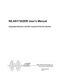
Table of Contents
Introduction...............................................................................2
Distribution Systems.................................................................4
Panelboards...............................................................................6
Overcurrent Protection Devices.................................................9
Panelboard Construction.......................................................... 19
Individual Overcurrent Protection............................................27
Panelboards Main Configurations............................................29
Power Supply Systems............................................................35
Service Entrance Panelboards.................................................38
Panelboard Grounding.............................................................40
Ground Fault Protection...........................................................44
Panelboard Interrupting Ratings...............................................46
Siemens P Series Panelboards................................................48
P1, P2, and P3 Panelboards.....................................................50
P4 and P5 Panelboards............................................................54
P Series Panelboard Catalog Numbers....................................55
Quick-Spec Coordination Panelboards.....................................58
Additional Types of Panels and Cabinets..................................59
Accessories.............................................................................60
Review Answers......................................................................66
Final Exam...............................................................................68
Introduction
Welcome to another course in the STEP series, Siemens
Technical Education Program, designed to help our distributors
and customers better understand Siemens Industry, Inc.
products. This course covers Basics of Panelboards.
Upon completion of Basics of Panelboards, you will be able to:
•
Explain the role of panelboards in a power distribution
system
•
Define a panelboard according to the National Electrical
Code®
•
Distinguish between a lighting and appliance panelboard
and a power panelboard
•
Explain the need for circuit protection
•
Distinguish between a main breaker panelboard and a
main lug only panelboard
•
Identify the most common power supply systems for
panelboards
•
Explain the use of panelboards as service-entrance
equipment
•
Describe the proper grounding techniques of service
entrance and downstream panelboards
•
Describe the five Siemens P series panelboard models
•
Identify key ratings of Siemens P series panelboards
•
Identify Siemens P series panelboard options
•
Identify additional Siemens panelboard types
This knowledge will help you better understand panelboard
applications. In addition, you will be better prepared to discuss
panelboards with others. You should complete Basics of
Electricity and Basics Circuit Breakers before attempting
Basics of Panelboards. An understanding of many of the
concepts covered in Basics of Electricity and Basics of Circuit
Breakers is required for Basics of Panelboards.
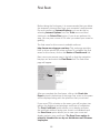
After you have completed this course, if you wish to determine
how well you have retained the information covered, you can
complete a final exam online as described later in this course. If
you pass the exam, you will be given the opportunity to print a
certificate of completion from your computer.
NFPA70®, National Electrical Code®, and NEC® are registered
trademarks of the National Fire Protection Association®,
Quincy, MA 02169.
NEMA® is a registered trademark and service mark of the
National Electrical Manufacturers Association, Rosslyn, VA
22209.
Underwriters Laboratories Inc.® and UL® are registered
trademarks of Underwriters Laboratories Inc., Northbrook, IL
60062-2096.
Other trademarks are the property of their respective owners.
Distribution Systems
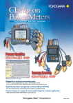
Power distribution systems are used in every residential,
commercial, and industrial building to safely control the
distribution of electrical power throughout the facility.
Residential Power
Distribution Most of us are familiar with the power distribution system
found in the average home. Power, purchased from a utility
company, enters the house through a metering device. The
power is then distributed by a load center to various branch
circuits for lighting, appliances, and electrical outlets.
Utility Power
Meter
Main Circuit Breaker
Load Center
Branch Circuit Breakers
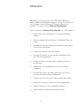
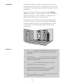
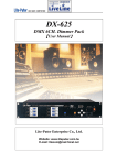
Commercial and Industrial
Power Distribution
Power distribution systems used in multi-family, commercial,
and industrial facilities are more complex. A power distribution
system consists of metering devices to measure power
consumption, main and branch disconnects, protective devices,
switching devices to start and stop power flow, conductors,
and transformers. Power may be distributed through various
switchboards, transformers, and panelboards.
Good distribution systems don’t just happen. Careful
engineering is required so that the distribution system safely
and efficiently supplies adequate electric service to existing
loads and has expansion capacity for possible future loads.
Exterior Wall
Utility Power
Disconnect Switch
Transformer
Switchgear in
Outdoor Enclosure
Switchboard
Motor Control
Power Panelboad
Lighting and Appliance
Panelboard
Panelboards
Electrical distribution systems, whether simple or complex,
typically include panelboards, the focus of this course.
Even the load center used in a home is a type of panelboard.
However, the focus of this course is on panelboards used in
commercial and industrial facilities.
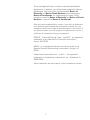
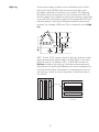
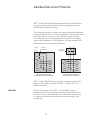
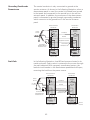
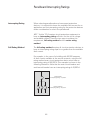
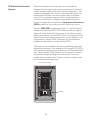
Panelboard Definition
A panelboard is a type of enclosure for overcurrent protection
devices and the busses and connections that provide power
to these devices and their associated circuits. According to the
National Electrical Code® (NEC®), a panelboard is:
•
•
•
•
Used to control light, heat, or power circuits
Placed in a cabinet or cutout box
Mounted in or against a wall
Accessible only from the front
Used to Control
Light, Heat, or
Power Circuits
Placed in a
Cabinet or
Cutout Box
Flush Mounted
Mounted in or
Against a Wall
Accessible Only
From the Front
Surface Mounted
1.75 in.
(44 mm)
0.25 in.
(6 mm)
For additional information, refer to National Electrical Code®
Article 408, Switchboards and Panelboards.
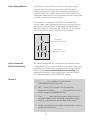
Panelboards are frequently divided into two categories:
•
•
Lighting and appliance branch-circuit panelboards
Power panelboards (also called distribution
panelboards)
Lighting and Appliance
Panelboard
Power Panelboards
Prior to the 2008 National Electrical Code®, the distinction
between these two panelboard types was described in NEC®
Articles 408.34 and 408.35. These articles placed restrictions
on lighting and appliance panelboards and indicated that
panelboards that did not comply with these restrictions were
defined as power panelboards.
For example, a lighting and appliance, branch-circuit panelboard
had to have more than ten percent of its overcurrent protection
devices (not including main devices) protecting lighting and
appliance branch circuits. A lighting and appliance branch circuit
is one with a connection to the panelboard neutral and an
overcurrent protection device rated for 30 amps or less. For the
purpose of this definition, each pole of a device is considered
as one device. Additionally, a lighting and appliance panelboard
was allowed a maximum of 42 overcurrent protection devices
(poles) in any one cabinet or cutout box.
Articles 408.34 and 408.35 and their associated restrictions
were removed from the National Electrical Code® beginning
with the 2008 code. However, the terms lighting and appliance
panelboard (also called a lighting panel) and power panelboard
(also called a power panel or distribution panelboard) are still
widely used.
Review 1
1.
A ________ system safely controls the distribution of
electrical power throughout a facility.
2. Which of the following descriptions is not correct
according to the NEC® definition for a panelboard?
a.Controls light, heat, or power circuit
b.Accessible from the front or rear
c.Mounted in or on a wall
d.Placed in a cabinet or cutout box
3. The articles that differentiate a lighting and appliance
branch-circuit panelboard and a power panelboard were
removed from the NEC® beginning with the ________
code.
Overcurrent Protection Devices
Because current flow in a conductor always generates heat,
the greater the current flow, the hotter the conductor. Excess
heat is damaging to electrical conductors. For that reason,
conductors have a rated continuous current carrying capacity or
ampacity. Current beyond the rated capability of a conductor is
referred to as overcurrent. Overcurrent can result from a short
circuit, an overload, or a ground fault.
Normal Current Flow
Excessive Current Flow
A short circuit occurs when two bare conductors touch
causing the resistance between the conductors to drop
significantly. This reduction in resistance causes an immediate
and destructive increase in current. An overload is a typically
a much lower current than a short circuit. An overload occurs
when too many devices are connected to a circuit or when
electrical equipment is made to work beyond its rated
capabilities. Finally, a ground fault occurs when current takes
an undesired path to ground. The level of ground fault current
depends on the resistance of the path and the amount of
voltage applied.
Overcurrent protection devices are used to protect
conductors from excessive current flow. Some overcurrent
protection devices only provide protection in the event of a
short circuit, some provide both short circuit and overload
protection, and some devices provide protection in the event of
any of the three overcurrent types.
Circuit protection would be unnecessary if overcurrents could
be eliminated. Unfortunately, overcurrents do occur and, when
an overcurrent occurs, a protection device must automatically
disconnect the electrical equipment from the voltage source.
An overcurrent protection device must be also able to recognize
the difference between a small overcurrent and a short
circuit and respond in the proper way. A small overcurrent is
often allowed to continue for a short time, but, as the current
magnitude increases, the protection device must respond
faster. Short circuits must be interrupted immediately.
Fuse
A fuse is one type of overcurrent protection device. A fuse is a
one-shot device. The heat produced by overcurrent causes the
current carrying element to melt open, disconnecting the load
from the source voltage.
Fuse During Fault
Fuse After Fault
Non-time-delay Fuses
Non-time-delay fuses provide excellent short circuit
protection. When an overcurrent occurs, heat builds up rapidly
in the fuse. Non-time-delay fuses usually hold 500% of their
rating for approximately one-fourth second, after which the
current-carrying element melts. This means that these fuses
cannot be used in motor circuits, which often have large in-rush
currents when a motor starts.
Time-delay Fuses Time-delay fuses provide overload and short circuit protection.
Time-delay fuses used in motor applications usually allow
several times the rated current for a short time to allow motors
to start without blowing the fuse.
10
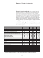
Fuse Classes
Underwriters Laboratories (UL) establishes and standardizes
basic performance and physical specifications for products
that undergo its safety test procedures. Among the standards
developed by UL are standards for classes of low voltage
fuses (fuses with voltage ratings of 600 volts or less). The
following table shows the fuse classes most commonly found
in panelboards.
U L F use
C lass
V oltage R atings
A m pere
R atings
Interrupting
R atings
H
250 and 600 V A C
up to 600 A
10 k A
600 V A C
up to 600 A
200 k A
300 V D C
up to 30 A
100 k A
500 V D C
up to 600 A
100 k A
600 V A C
601 to 6000 A
200 k A
500 V D C
601 to 3000 A
100 k A
250 and 600 V A C
up to 600 A
200 k A
250 V D C
up to 600 A
100 k A
600 V D C
up to 600 A
100 k A
250 and 600 V A C
up to 600 A
200 k A
300 V D C
up to 30 A
20 k A
600 V D C
35 to 400 A
20 k A
300 V A C
up to 1200 A
200 k A
600 V A C
up to 800 A
200 k A
160 V D C
up to 1200 A
50 k A
300 V D C
up to 1200 A
100 k A
J
L
R K -1
R K -5
T
Fuses are grouped into classes based on their operating and
construction characteristics. Each class has an interrupting
rating, which is the maximum current the fuse is capable of
safely interrupting. Fuses also have maximum continuous
current and maximum voltage ratings.
When selecting fuses, it is a good idea to refer to the fuse
manufacturer’s application data to make sure that a specific
fuse is appropriate for the type of loads involved.
11
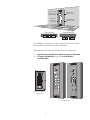
Fusible Disconnect Switch
A fusible disconnect switch is one type of device used on
panelboards to provide overcurrent protection. Fuses located in
the switch are selected to handle the specified levels of current
and voltage and to provide the appropriate interrupting rating.
Siemens Vacu-Break fusible switches, through 600 A, feature
a Clampmatic action that holds the current carrying contact
surfaces in a vise-like grip. Heat build-up due to current is
minimized.
When the switch is moved to the OFF position, the movable
contact snaps from between the jaws providing a quick, clean
break. Twin arcs are produced which are smaller and extinguish
quicker than a single arc produced by other designs.
The contacts are surrounded by an enclosed arc chamber
which absorbs much of the heat from the arching. The enclosed
chamber limits oxygen to more rapidly cool and extinguish arcs.
12
High Contact Pressure Fusible Switch Siemens high contact pressure (HCP) fusible switches have
continuous current ratings from 400 A to 1200 A.
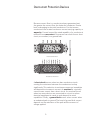
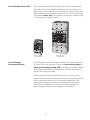
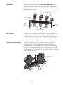
Circuit Breaker
Another device used for overcurrent protection is a circuit
breaker. Although some circuit breakers do incorporate fuses,
most do not, but, like a fusible switch, a circuit breaker provides
overcurrent protection and a manual means of controlling power
distribution.
!
!
DANGER
!
PELIGRO
!
DANGER
!
PELIGRO
!
DANGER
DANGER
Type/Typo
Frame MG
ON
Type/Typo
Frame MG
ON
NNG
I
DANGER
!
!
PELIGRO
DANGER
!
NNG
Type/Typo
Frame MG
NMG
I
ON
I
OFF
O
Type/Tipo
Frame - LG
OFF
ON
OFF
800A
O
I
O
Type/Tipo
NDG
Frame DG
ON
OFF
600A
I
O
Type/Tipo
NDG
Frame DG
OFF
150A
O
Type/Tipo
ON
I
Frame FG
ON
OFF
150A
O
OFF
ESC
13
I
250A
O
NFG
When an overcurrent occurs, the circuit breaker trips to remove
power from the circuit. The greater the overcurrent, the more
rapidly the circuit breaker trips. Once the overcurrent condition
has been corrected, a simple flip of the breaker’s operating
handle restores the circuit.
The ability to restore a circuit without replacing a fuse is one
of the key advantages of a circuit breaker. However, circuit
breakers have other advantages as well. For example, some
circuit breakers have adjustments or a replaceable trip unit to
allow the level of fault current required to trip the breaker to be
set to match the application. Some circuit breakers also have
communication capability to allow information to be sent to
power monitoring equipment or display devices.
Circuit Breaker
Operating Handle Positions
“ON”
“TRIPPED”
“OFF”
Continuous Amps
Ir = % In
80 90 100
65
20
50
30
40
40
30
50
20
100 90 80 65
Instantaneous
Pickup 8 10
x Ir
6
15
4
20
2
Long
Time
Delay @ 6 x Ir
Short Time
Pickup 4 7
Max
40
30
.1s
1.5
10
10
1.5
4 .2s
7
7
.05s
4
10
1.5
1.5
10
Delay 7 24 .2s @
I t 6xI
x Ir
Secs
[ ]
r
Ground Fault
Pickup
70
20 30 .2s
55
40
40
55
30
.1s
70
25
20
20
I2t
70 55 40 30
Delay
.4s
Ig=%In
@.5 In
Adjustments Found on Some Circuit Breakers
Circuit Breaker
Voltage Rating
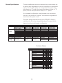
Circuit breakers are rated according to the maximum voltage
they can handle. The voltage rating is a function of the circuit
breaker’s ability to suppress the internal arc that occurs when
the circuit breaker’s contacts open.
The voltage rating of the circuit breaker must be at least equal
to the circuit voltage. The voltage rating of a circuit breaker can
be higher than the circuit voltage, but never lower. For example,
a 480 VAC circuit breaker could be used in a 240 VAC circuit, but
a 240 VAC circuit breaker could not be used in a 480 VAC circuit.
14
Some circuit breakers have what is referred to as a “slash”
voltage rating, such as 120/240 VAC or, as shown in the
following graphic, 600/347 VAC for 2, 3, or 4-pole NEB breakers
and 115/250 VDC for 2-pole NEB breakers. In such cases, the
breaker may be applied in a circuit where the nominal voltage
between any conductor and ground does not exceed the lower
rating and the nominal voltage between conductors does not
exceed the higher rating.
Type/Tipo NEB
Frame-EG
100 Amp
O
N
O
F
F
l
O
100
NEB Circuit Breaker
NEG
Poles
NEB
HEG
HEB
1, 2, 3, 4 1, 2, 3 1, 2, 3, 4 1, 2, 3
Amperes, Continous
1-Pole
15-125
15-125
15-125
15-125
2-Pole
15-125
15-125
15-125
15-125
3-Pole
15-125
15-125
15-125
15-125
4-Pole
15-125
347
347
15-125
347
347
1-Pole
AC
Volts (50/60 Hertz)
2-Pole
3-Pole
600/347 600/347 600/347 600/347
4-Pole
UL Interrupting Rating Symetrical RMS Amperes
DC
Circuit Breaker Continuous Current Rating
240 V
85,000
85,000 100,000 100,000
480V
35,000
35,000
65,000
65,000
22,000
22,000
25,000
25,000
600/347 V
Volts 2-Pole
125/250 125/250 125/250 125/250
Interrupting Rating - DC Amperes
35,000
35,000
42,000
42,000
Every circuit breaker has a continuous current rating which is
the maximum continuous current a circuit breaker is designed
to carry without tripping. The current rating is sometimes
referred to as the ampere rating because the unit of measure
is amperes, or, more simply, amps.
15
The rated current for a circuit breaker is often represented as
In, as shown in the following chart for an NEB circuit breaker.
This should not be confused with the current setting (Ir) which
applies to those circuit breakers that have a continuous current
adjustment. Ir is the maximum continuous current that circuit
breaker can carry without tripping for the given continuous
current setting. Ir may be specified in amps or as a percentage
of In.
NEG
Poles
A vailable
A m pere
R atings (I n )
15
20
25
30
35
40
45
50
A 60 A
A 70 A
A 80 A
A 90 A
A 100 A
A 110 A
A 125 A
A
NEB
HEG
HEB
1, 2, 3, 4 1, 2, 3 1, 2, 3, 4 1, 2, 3
Amperes, Continous
1-Pole
15-125
15-125
15-125
15-125
2-Pole
15-125
15-125
15-125
15-125
3-Pole
15-125
15-125
15-125
15-125
4-Pole
15-125
347
347
15-125
347
347
1-Pole
AC
Volts (50/60 Hertz)
2-Pole
3-Pole
600/347 600/347 600/347 600/347
4-Pole
UL Interrupting Rating Symetrical RMS Amperes
DC
240 V
85,000
85,000 100,000 100,000
480V
35,000
35,000
65,000
65,000
22,000
22,000
25,000
25,000
600/347 V
Volts 2-Pole
Interrupting Rating - DC Amperes
125/250 125/250 125/250 125/250
35,000
35,000
42,000
42,000
Conductors are rated for how much current they can carry
continuously. This is commonly referred to as the conductor’s
ampacity. In general, the ampere rating of a circuit breaker and
the ampacity of the associated conductors must be at least
equal to the sum of any noncontinuous load current plus 125%
of the continuous load current.
Siemens circuit breakers are rated on the basis of using 60° C
or 75° C conductors. This means that even if a conductor with
a higher temperature rating were used, the ampacity of the
conductor must be figured on its 60° C or 75° C rating.
16
Circuit Breaker Frame Size
The circuit breaker frame includes all the various components
that make up a circuit breaker except for the trip unit. For any
given frame, circuit breakers with a range of current ratings can
be manufactured by installing a different trip unit for each rating.
The breaker frame size is the highest continuous current rating
for a breaker with a given frame.
!
DANGER
!
PELIGRO
DANGER
!
Type/Typo
Frame MG
ON
OFF
Type/Tipo
NMG
I
800A
O
NDG
Frame DG
ON
OFF
I
150A
O
150 Amp Frame
Circuit Breaker
800 Amp Frame
Circuit Breaker
Circuit Breaker
Interrupting Rating
Circuit breakers are also rated according to the maximum level
of current they can interrupt. This is the interrupting rating or
ampere interrupting rating (AIR). Because UL and IEC testing
specifications are different, separate UL and IEC interrupting
ratings are usually provided.
When designing a power distribution system, a main circuit
breaker must be selected that can interrupt the largest potential
fault current that can occur in the selected application. The
interrupting ratings for branch circuit breakers must also be
taken into consideration, but these interrupting ratings will
depend upon whether series ratings can be applied.
17
The interrupting ratings for a circuit breaker are typically
specified in symmetrical RMS amperes for specific rated
voltages. As discussed in Basics of Electricity, RMS stands
for root-mean-square and refers to the effective value of an
alternating current or voltage. The term symmetrical indicates
that the alternating current value specified is centered around
zero and has equal positive and negative half cycles. Siemens
circuit breakers have interrupting ratings from 10,000 to
200,000 amps.
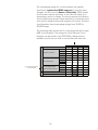
The following table shows the UL interrupting ratings for type
NEB circuit breakers. The ratings for other Siemens circuit
breakers can be found in the SPEEDFAX catalog which is
available in print form as well as on the Siemens web site.
NEG
Poles
NEB
HEG
HEB
1, 2, 3, 4 1, 2, 3 1, 2, 3, 4 1, 2, 3
Amperes, Continous
1-Pole
15-125
15-125
15-125
15-125
2-Pole
15-125
15-125
15-125
15-125
3-Pole
15-125
15-125
15-125
15-125
4-Pole
15-125
347
347
15-125
347
347
1-Pole
AC
Volts (50/60 Hertz)
2-Pole
3-Pole
600/347 600/347 600/347 600/347
4-Pole
Only UL Ratings Shown
in this Example
UL Interrupting Rating Symetrical RMS Amperes
DC
240 V
85,000
85,000 100,000 100,000
480V
35,000
35,000
65,000
65,000
600/347 V
22,000
22,000
25,000
25,000
Volts 2-Pole
Interrupting Rating - DC Amperes
18
125/250 125/250 125/250 125/250
35,000
35,000
42,000
42,000
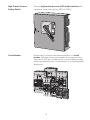
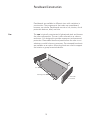
Panelboard Construction
Panelboards are available in different sizes with variations in
construction. The components that make up a panelboard,
however, are similar. Panelboards contain a can, interior, circuit
protection devices, label, and trim.
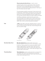
Can
The can is typically constructed of galvanized steel and houses
the other components. The can is also referred to as a box or
enclosure. It is designed to provide component and personnel
protection. Removable blank end panels allow the user to cut
whatever conduit holes are necessary. Pre-stamped knockouts
are available as an option. Mounting studs are used to support
the interior or group mounted devices.
Can
Mounting Stud
Removable
End Panel
19
Interior
The interior consists of several components, including
overcurrent protection devices, bus bars and insulated neutral
bus bars. A lighting panel interior is mounted to the four
mounting studs in the can. Jacking screws (not shown) allow
adjustment of the interior within the enclosure. Bus Bars
A bus bar is a conductor that serves as a common connection
for two or more circuits. Standard bus bars on Siemens
panelboards are made of aluminum, but copper bus bars are
available as an option.
NEC® Article 408 requires three-phase panelboard bus bars to
have phases in sequence as shown in the following graphic so
that an installer can have the same fixed phase arrangement in
each termination point in a panelboard or switchboard. NEC®
Article 408 does provide an exception to this rule, refer to this
article for additional details.
A
B
C
A
B
C
Horizontal
(Top-to-Bottom)
Front View
Vertical
(Left-to-Right)
Front View
Front
A
Top View
B
C
Back
20
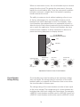
High Leg
Some power supply systems use a transformer with a threephase, four-wire (3Ø4W), delta-connected secondary with
grounded, center-tap connection on one phase. The following
illustration shows an example of such a system with 240 volts
phase-to-phase. The midpoint of one phase winding is grounded
to provide 120 volts between phase A and neutral and 120 volts
between phase C and neutral. Between phase B and neutral,
however, the voltage is 208 volts. This is referred to as the high
leg.
NEC® Article 110.15 requires that the high leg conductor or bus
bar be permanently marked with an orange finish “or by other
effective means.” In addition, NEC® Article 408.3 states the
B phase should be the high leg. Other bus bar arrangements
are permitted for existing installations, but these arrangements
must be marked. More information on calculating the value of
the high leg, as well as connecting loads, is discussed later in
the course.
High Leg
Vertical
Horizontal
21
Split Neutral
Siemens panelboards feature a split neutral design which
means that neutral connections are available on both sides of
the panelboard. Split neutrals are connected by means of an
insulated neutral bus bar.
A
Service Neutral Lug
B
C
Neutral Bus Bar
Branch
Neutral
Lugs
Branch
Neutral
Lugs
Insulation
Supply Bus Bars
200% Neutral
Some loads can cause harmonics and non-linear loading on a
distribution system. This requires special consideration when
ordering a panelboard. One way to deal with non-linear loads
is to double the capacity of the panelboard neutral. A 200%
neutral is an available option on Siemens panelboards.
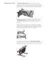
Circuit Protection Devices
While it is common for load centers to have plug-in branch
circuit breakers, circuit breakers used in panelboards for
commercial and industrial applications typically bolt on to the
bus bars. For example, the following illustration shows two BL
circuit breakers, one is mounted to the panelboard bus and the
other is being mounted.
BL Circuit Breaker
Bus Bars
22
Circuit Identification
Specifications typically require panelboard circuit terminals to
be labeled or for a wiring diagram to be provided. One approach
for numbering terminals is to use odd numbers for poles on
the panelboard’s right (your left as you face the panelboard)
and even numbers on the panelboard’s left. This is sometimes
referred to as NEMA numbering. For some specifications,
vertical numbering is required.
NEMA Numbering
Panelboard Label
Vertical Numbering
The label identifies the panelboard’s type, voltage rating, and
ampacity.
System
Panel Type
208Y/120 V
P1
250 Amps Max
(see main device or breaker)
Provisions are for device types:
100 A max: BL BLH HBL BLF BLHF BLE
BLEH LG BAF BAFH BQD
Minimum size UL listed cabinet or cut-out
box for this panel: 20”W x 5.75”DP x 56”H
Siemens Industry, Inc. Atlanta, Ga. USA
For emergency service call
1-800-241-4453
23
15-A-1034-01 Rev.2
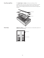
Dead Front and Trim
The dead front and trim are the front surfaces of the
panelboard that cover the interior. The trim includes an access
door. These components provide access to the overcurrent
devices while sealing off the bus bars and internal wiring from
contact.
Access Door
Trim
Dead Front
Filler Plates
QF3 filler plates are used to cover any unused pole spaces not
filled by a circuit breaker.
Circuit Breaker
QF3 Filler Plate
24
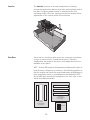
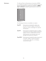
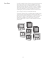
Enclosures
The National Electrical Manufacturers Association (NEMA)
has established guidelines for electrical equipment enclosures.
Siemens panelboards are supplied as standard in a NEMA
Type 1 enclosure intended for general purpose indoor use.
The following enclosures are available as an option:
Type 3R
Enclosures are intended for outdoor use
primarily to provide a degree of protection
against rain, sleet and damage from external
ice formation.
Type 4X
Enclosures are intended for indoor or outdoor
use primarily to provide a degree of protection
against corrosion, windblown dust and rain,
splashing water, hose-directed water, and
damage from external ice formation.
Type 3R/12
Enclosures are intended for indoor use primarily
to provide a degree of protection against
circulating dust, falling dirt, and dripping
noncorrosive liquids.
25
Installation
Panelboard installation requires careful planning to ensure a
safe environment for personnel and equipment. Article 110.26
of the NEC® covers spaces about electrical equipment, such as
panelboards.
The intent of Article 110.26 is to provide enough working
space for personnel to examine, adjust, service, and maintain
energized equipment. Article 110.26 sets requirements for
depth, width, and height of a working space.
In addition, Article 110.26 discusses entrance requirements
to the working space as well as requirements for dedicated
equipment space for indoor and outdoor applications. Refer
to this article if you have questions about working space
requirements.
Review 2
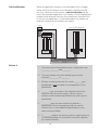
1.
A ________ is the part of the panelboard enclosure that
mounts in a wall (flush mounting) or to a wall (surface
mounting).
2. A panelboard ________ consists of several components,
including overcurrent protection devices, bus bars and
insulated neutral bus bars.
3. A ________ is a conductor that serves as a common
connection for two or more circuits.
4. Siemens lighting panels feature a ________ neutral
design, which means that neutral connections are
available on both sides of the panelboard.
5. The ________ and ________ are the front surfaces of the
panelboard that cover the interior.
26
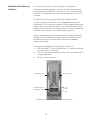
Individual Overcurrent Protection
NEC® Article 408.36 requires panelboards to be protected by
an overcurrent protection device with a rating that does not
exceed the panelboard’s rating.
The following illustration shows two ways individual panelboard
overcurrent protection can be accomplished. A main overcurrent
protection device, such as a circuit breaker, can be located
as an integral part of the panelboard or located on the supply
side of the panelboard. In this example, the main breaker and
panelboard are both rated for 600 amps.
Supply
600 Amp
Circuit Breaker
600 Amp Panelboard
Main Overcurrent Protection
is an Integral Part of the Panelboard
600 Amp
Circuit Breaker
600 Amp Panelboard
Main Overcurrent Protection
is Remote from the Panelboard
NEC® Article 408.36 does provide for exceptions to this rule.
Refer to the complete article and NEC® Article 230.71 for
additional details.
Split Bus
One of the exceptions to NEC® Article 408.36, allows
panelboards to be protected by two main circuit breakers or
two sets of fuses, provided that the combined current rating
of these devices does not exceed the current rating of the
panelboard.
27
When two main circuit breakers are used in a panelboard, a
split bus is used. Half of the branch circuits are protected by
one main circuit breaker, and the other half are protected by
the other main circuit breaker. Keep in mind that the combined
ratings for these circuit breakers must be no greater than the
panelboard rating.
200 Amp Service
100 Amp
Main Breakers
Panelboard Supplied
by a Transformer
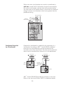
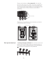
Frequently a panelboard is supplied by the secondary of a
transformer. According to NEC® Article 408.36, individual
protection for the panelboard must be provided on the
secondary side of the transformer. The overcurrent protection
device can be installed either ahead of or in the panelboard.
Transformer
Transformer
Externally
Mounted
Breaker
Neutral Bus
Main
Breaker
Panelboard
Neutral Bus
Panelboard
NEC® Article 408.36 (B) provides an exception to this rule.
Refer to this article and Article 240.21 for additional details.
28
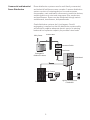
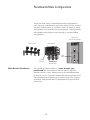
Panelboards Main Configurations
There are three types of panelboard main configurations:
main lug only, main breaker, and main switch. In this context,
the term switch refers to a fusible switch. All three of these
configurations are available for power panels. Lighting panels
are available with either a main lug only or a main breaker
configuration.
Main Switch
(Only for Power Panels)
Main Lug Only
Main Breaker
Main
Switch
Line Side
Terminals
Main Bus Bars
Main Breaker Panelboard
The incoming supply cables of a main breaker type
panelboard are connected to the line side of the main
breaker, which, in turn, feeds power to the panelboard and
its branch circuits. The main breaker disconnects power from
the panelboard and protects the system from short circuits,
overloads, and ground faults (if equipped with ground fault
protection).
29
Siemens main breakers are bus connected to the main bus
bars. This means there are no cable connections required from
the main circuit breaker to the lugs on the main bus bars. Bus
connecting provides a higher degree of circuit integrity because
there is less chance for loose connections which lead to
overheating.
Bus Connected
Depending on the panelboard, the main breaker can either be
mounted horizontally or vertically.
To Branch Circuits
Supply
Supply
Main
Breaker
Main
Breaker
Branch
Breaker
Branch
Breaker
Main Breaker Mounted Horizontally
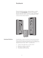
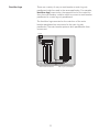
Main Lug Only Panelboard
Main Breaker Mounted Vertically
A main lug only type panelboard does not have a main circuit
breaker. The incoming supply cables are connected directly to
the bus bars. Primary overload protection for the panelboard is
not provided as an integral part of the panelboard.
30
Feed-thu Lugs
There are a variety of ways a main breaker or main lug only
panelboard might be used in the same application. For example,
feed-thru lugs, mounted on the opposite end of the main bus
from the main breaker, could be used to connect a main breaker
panelboard to a main lug only panelboard.
The feed-thru lugs mounted on the main bus of the main
breaker panelboard are connected to the main lug only
panelboard. The main breaker protects both panelboards from
overcurrent.
Supply
Main
Breaker
Feed-thru
Lugs
Main Breaker Panelboard
31
Main Lug Only Panelboard
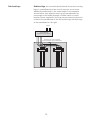
Sub-feed Lugs
Sub-feed lugs are mounted directly beside the main incoming
lugs on a panelboard and are used to connect one or more
additional panelboards to the same feeder. In the example
shown below, two adjacent main lug only panelboards are
connected to the feeder through a fusible switch or circuit
breaker. Power supplied by the overcurrent protection device is
routed to the panelboard on the left and through sub-feed lugs
to the panelboard on the right.
Supply
Circuit Breaker
Fused Disconnect Switch
Sub-feed Lugs from Left Panel
Connect to Main Lugs on Right Panel
32
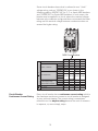
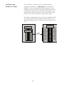
Unit Space and Number of Circuits
Circuit breaker or fusible switch mounting height is
sometimes referred to as unit space. The unit space
available for mounting branch devices depends on the
panelboard type, enclosure dimensions, and main device
configuration. Because the unit space required by circuit
breakers and fusible switches varies, the number branch
devices that can be mounted in a panel also varies.
For Siemens panelboards, the unit space available and the
unit space required by each device can be found in the
Speedfax catalog, which is available on the Siemens web
site.
Main Device
Main Device
Branch Device
Unit space
available for
branch devices
Power Panelboard
1
10
2
11
3
12
4
13
5
14
6
15
7
16
8
17
9
18
Lighting Panel
33
Sub-feed Breaker
When an application requires a circuit breaker that is a larger
frame size than the branch circuit breakers available and will
not fit in a branch circuit location, a sub-feed breaker can be
used. One possible application is to supply a second panelboard
located some distance from the first panelboard. However this
is not the only application. A sub-feed breaker can supply any
load that a branch circuit breaker can supply.
Supply
Main Lug Only Panelboard
Main
Breaker
Sub-feed
Breaker
Conduit
Review 3
1.
The three types of panelboard main configurations are
________, ________, and ________.
2. The main breaker of a main breaker panel can be
mounted _________ or ________.
3. Primary overload protection for a main _______ type
panelboard is not provided as an integral part of the
panelboard.
4. ________ lugs, mounted on the opposite end of the
main bus from the main breaker, can be used to
connect a main breaker panelboard to a main lug only
panelboard.
5. _________ lugs are mounted directly beside a
panelboard’s main incoming lugs and are used to
connect one or more additional panelboards to the
same incoming feeder.
6. A ________ breaker can also be used to supply power to
a second panelboard or a load that cannot be supplied
by a branch breaker.
34
Power Supply Systems
Panelboards receive power from a variety of sources. For
example, a downstream panelboard typically receives power
from an upstream panelboard or switchboard. However,
power for the distribution system originates from a utility
power company. Power from the power company is stepped
down through a transformer for distribution to a residential,
commercial, or industrial facility.
There are a number of ways that the transformer secondary
windings providing service may be configured. In order to
properly select a panelboard, you need to understand which
voltage and system will be connected. The following examples
show a few of the more common systems, but other systems
and voltages are also common.
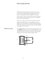
1Ø3W Power System
The following diagram illustrates a common single-phase, threewire (1Ø3W) distribution system. As this diagram shows, the
voltage between the neutral connection (N) of the transformer
secondary and either side of the secondary is 120 V and the
voltage across the entire secondary winding is 240 V.
Transformer
Secondary
A
120 Volts
Neutral
Primary
240 Volts
120 Volts
B
Ground
35
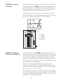
3Ø4W Wye-connected
Transformer
The following illustration shows the secondary of a 480 Y/277 V
three-phase, four-wire (3Ø4W), wye-connected transformer. The
“480 Y” indicates the transformer is wye-connected and has
480 volts between any two phases. The “277 V” indicates the
voltage between any phase and neutral (N) is 277 V.
If you know the phase voltage for a system like this, you can
calculate the phase-to-phase voltage by multiplying 1.732 times
the phase-to-neutral voltage (277 V x 1.732 = 480 V).
A
480 Volts 480 Volts
B
N
480 Volts
C
}
277 Volts
A-B
B-C
C-A
A-N
B-N
C-N
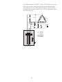
3Ø4W Delta-connected
Transformer, BØ High Leg
480 Volts
480 Volts
480 Volts
277 Volts
277 Volts
277 Volts
A three-phase, four-wire (3Ø4W), delta-connected secondary
works a little differently. The following illustration shows a deltaconnected secondary with 240 V phase-to-phase. The midpoint
of one phase winding is grounded to provide 120 V between
phase A or C and the neutral connection. Between phase B and
neutral, however, the voltage is 208 V. As previously discussed,
this is referred to as the high leg.
Four-wire, delta-connected transformers are most often
wired so that the B phase is the high leg. The high leg can be
calculated by multiplying the phase A (or C) to neutral voltage
times 1.732 (120 V x 1.732 = 208 V).
It is important to note that not all circuit breakers are suitable
for use on the high leg. For example, breakers rated for 120/240
volts can be installed on legs rated for 120 volts, but cannot be
installed on the high leg (208 volts).
36
You may remember that NEC® Article 110.15 requires that the
high leg bus bar or conductor be permanently marked with
an orange finish “or by other effective means.” This will help
prevent someone from connecting a 120 V single-phase load to
the 208 V high leg.
A
240 Volts
N
120 Volts
B
208 Volts
240 Volts
C
240 Volts
120 Volts
A-B
B-C
C-A
A-N
B-N
C-N
B Phase Bus Bar
37
240 Volts
240 Volts
240 Volts
120 Volts
208 Volts
120 Volts
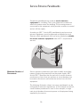
Service Entrance Panelboards
Sometimes panelboards are used as service entrance
equipment for a building. This is the equipment located near
where the power enters the building. The incoming power is
connected to this equipment which provides a means to control
and cut off the supply.
According to NEC® Article 408, panelboards used as service
entrance equipment must be approved and labeled as such.
Siemens offers panelboards that are factory labeled as suitable
for service entrance equipment when NEC® requirements
are met.
Panelboard
Service
Entrance
Meter
Maximum Number of
Disconnects
Service entrance conductors must have a readily accessible
means of being disconnected from the power supply. NEC®
Article 230.71 specifies that for each set of service entrance
conductors no more than six switches or circuit breakers can
be used to disconnect and isolate the service from all other
equipment.
The following illustration shows two ways panelboards can be
configured to meet this requirement. In the example on the left,
a main breaker panelboard is used. In this example, a single
main circuit breaker disconnects power to all equipment being
supplied by the service.
38
In the example on the right, a main lug only panelboard is
equipped with up to six circuit breakers to disconnect power to
all equipment being supplied by the service.
Regardless of which of these examples is used, each circuit
breaker must be clearly labeled to show the load it supplies.
Main Breaker Panelboard
with Branch Circuits
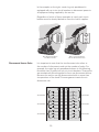
Disconnects Versus Poles
Main Lug Only Panelboard
with Six Service DIsconnects
It is important to note that the six disconnect rule refers to
the number of disconnects and not the number of poles. For
example, the main lug only panelboard shown in the following
illustration has 18 poles but only six circuit breakers. Three poles
are mechanically linked together to form one disconnect device.
Because the service can be disconnected with no more than
six operations of the hand. This arrangement meets the six
disconnect rule.
3-Pole Breaker
3-Pole Breaker
3-Pole Breaker
{
{
{
}
}
}
39
3-Pole Breaker
3-Pole Breaker
3-Pole Breaker
Panelboard Grounding
Grounding is an important aspect of any electrical equipment
and must be considered carefully. A ground connection is a
connection to earth or to a conductive object that is connected
to earth. The accompanying illustration, for example, shows
the neutral (N) conductor of a wye-connected transformer
connected to ground.
The intentional grounding of electrical equipment is done
to limit voltage differences between parts of a system. This
is necessary for the safety of personnel and the protection
of equipment and facilities. Article 250 of the NEC® covers
grounding and bonding requirements for electrical installations.
N
Ground
Grounding
Electrode
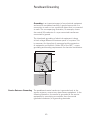
Service Entrance Grounding The panelboard neutral conductor is grounded only at the
service entrance, never at any downstream equipment. In the
following illustration, the neutral is grounded at the service
equipment by connecting a conductor from the neutral
(grounded conductor) to a grounding electrode.
40
The neutral and the panelboard enclosure are bonded together
at the service entrance so that the enclosure is also connected
to ground through the grounding electrode connector. Bonding
permanently joins metal parts to form a low-resistance path for
electrical current.
Service Entrance
Panelboard
Power
Source
Neutral
Bus
Neutral Bonded
to Can
Exterior Wall
Grounding
Electrode
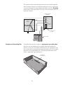
Equipment Grounding Bus
A panelboard may also require an equipment grounding bus
which is non-insulated and mounted inside the panelboard
directly to the can. All feeder and branch circuit equipment that
are connected to the equipment grounding bus are at the same
potential as the panelboard can. Siemens panelboards come
with an equipment grounding bus.
Equipment
Grounding Bus
41
Grounding Panelboards
Downstream
The neutral conductor is only connected to ground at the
service entrance. As shown in the following illustration, when a
downstream panel is used, the neutral is isolated from ground
in that panel and connected to the neutral bus in the service
entrance panel. In addition, the enclosure of the downstream
panel is connected to ground through a grounding conductor
which connects to the ground bus in the service entrance
panel.
Service Entrance
Panelboard
Main
Breaker
Power
Source
Downstream
Panelboard
Branch
Breaker
Sub-Feed
N
Neutral Bus
Insolated
Neutral
Bus
Neutral
Equipment Ground
Ground
Bus
Ground Bus
And Neutral Bus
Bonded to Can
Ground Bus
Bonded to Can
Branch Load
Fault Path
Ground
Bus
Branch Load
In the following illustration, load #2 has become shorted to its
metal enclosure. Fault current is returned to the source through
the path indicated. With a properly coordinated system, the
branch circuit breaker in the downstream panelboard will open,
removing the load from the power source.
Service Entrance
Panelboard
Main
Breaker
Power
Source
Downstream
Panelboard
Sub-Feed
N
Neutral Bus
Neutral
Branch
Breaker
Insolated
Neutral
Bus
Equipment Ground
Ground
Bus
Ground Bus
And Neutral Bus
Bonded to Can
Branch Load #1
42
Ground Bus
Bonded to Can
Ground
Bus
Branch Load #2
Short to
Ground
Review 4
1.
If the secondary of a four-wire, wye-connected
transformer is 480 V phase-to-phase, the phase to
neutral voltage is _____ V.
2. If the secondary of a four-wire, delta-connected, BØ
high leg transformer is 240 volts phase-to-phase,
determine the following phase to neutral voltages.
_____ V from A-N
_____ V from B-N
_____ V from C-N
3. According to NEC® Article 230.71, the maximum
number of disconnect devices that can be used to
disconnect and isolate the service from all other
equipment is ____ .
4. ________ permanently joins metal parts to form a lowresistance path for electrical current.
5. The ________ conductor is grounded only at the
service entrance equipment, never at any downstream
equipment.
43
Ground Fault Protection
A ground fault is a condition in which electrical current
unintentionally flows to ground. Because ground faults can
cause damage to equipment and can endanger lives, ground
fault protection is required in some situations.
For example, NEC® Article 230.95 requires ground fault
protection of equipment for service disconnects rated 1000
amps or more on solidly-grounded wye services exceeding 150
volts-to-ground but not exceeding 600 volts phase-to-phase.
Refer to the complete article for additional information.
Keep in mind that ground fault equipment protection must open
a circuit when ground fault current reaches 30 milliamps. In
contrast, ground fault circuit interrupters designed to provide
life protection must open a circuit at 5 milliamps (plus or
minus 1 milliamp). When ground fault protection is incorporated
into a panelboard, it is generally through use of circuit breakers
with ground fault protection.
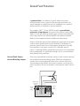
Ground Fault Sensor
Around Bonding Jumper
One way a ground fault protector works is with a sensor around
the insulated neutral bonding jumper. When an unbalanced
current from a line-to-ground fault occurs, current will flow in
the bonding jumper. When the current reaches a set level, the
shunt trip opens the circuit breaker, removing the load from the
line.
Breaker with
Shunt Trip
Option
Ground
Fault
Sensor
Ground
Fault
Relay
44
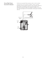
Ground Fault Sensor
Around all Conductors
Another way a ground fault protector works is with a sensor
around all the circuit conductors. When current is flowing
normally, the sum of all the currents is zero. However, a ground
fault causes an imbalance of the currents flowing in the
individual conductors. When the imbalance reaches a set level,
the shunt trip opens the circuit breaker, removing the load from
the line.
Breaker with
Shunt Trip
Option
Ground
Fault
Relay
Ground
Fault
Sensor
45
Panelboard Interrupting Ratings
Interrupting Rating
When selecting panelboards and overcurrent protection
devices, it is essential to know the available fault current for an
application and the interrupting rating for the protective devices
under consideration for use in the panelboard.
NEC® Article 110.9 requires circuit protection equipment to
have an interrupting rating sufficient for the circuit voltage
and available current. There are two ways to achieve this
requirement, full rating method and the series rating
method.
Full Rating Method
The full rating method requires all circuit protection devices to
have an interrupting rating equal to or greater than the available
fault current.
For example, in the case of a building with 65,000 amperes
of fault current available at the service entrance, using the full
rating method every circuit protection device must have an
interrupting rating of 65,000 A. This example is shown in the
following illustration. Note that the main circuit breaker and
each branch breaker have an interrupting rating of 65,000 A.
Main Breaker
Interrupting Rating = 65,000 A
Branch Breakers
Interrupting Rating = 65,000 A
46
Series Rating Method
An alterative to the full rating method is the series rating
method, which requires that the main upstream circuit
protection device must have an interrupting rating equal to
or greater than the available fault current of the system, but
subsequent downstream circuit protection devices connected
in series can be rated at lower values.
For example, a building with 42,000 A of available fault
current might have a breaker at the service entrance with an
interruption rating of 42,000 A and additional downstream
breakers rated at a lower level, but “sufficient for the current
that must be interrupted,” 18,000 A in this example.
Main Breaker
Interrupting Rating = 42,000 A
Branch Breakers
Interrupting Rating = 18,000 A
Series Connected
Short Circuit Rating
The series rating method is used when the selected series
combination of circuit protection devices has been tested and
certified by UL. Each series combination of circuit protection
devices has a series connected short circuit rating. For
additional information, refer to the Series Connected Short
Circuit Ratings tables in the SPEEDFAX catalog.
Review 5
1.
A ________ is a condition in which current
unintentionally flows to ground.
2. NEC® Article 110.9 requires circuit protection
equipment to have an ________ rating sufficient for the
circuit voltage and available current.
3. The ________ rating method requires selecting circuit
protection devices with individual interrupting ratings
equal to or greater than the available fault current.
4. Series connected circuit breaker combinations must be
tested and certified by ________.
47
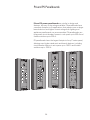
Siemens P Series Panelboards
Siemens P series of panelboards offers a stepped approach
to power distribution. The P1 panel fits the majority of lighting
panel needs in a cost effective package. P1 offers a flexible
design that virtually eliminates the impact of common mistakes
in feed direction or main lug versus main breaker selection. The
next step in the series is the P2 panel, which offers maximum
flexibility and options to fit demanding specifications. P3 is also
a flexible and innovative panel. Sized more like a lighting panel
for those tight areas, but with the power of a power distribution
panel. P4 is a mid-sized power distribution panel that can
include fusible switches as well as circuit breaker main and
branch devices. Finally, P5 incorporates larger fusible and circuit
breaker main and branch devices to provide maximum power to
the distribution system.
Key Panelboard Features
P1
P2
P3
P4
Lighting and Appliance Applications
●
●
●
●
Power Panelboard Applications
●
●
●
Convertible from Top Feed to Bottom Feed or Vice Versa
●
Change from Main Lug to Main Breaker or Add Subfeed
Breaker Without Changing Enclosure Size
●
Up to 250 A Up to 250 A Up to 250 A
Space-saving, Horizontally Mounted Main Breaker
●
Short-circuit Rating Label Giving Performance Level
●
●
●
●
Standard Aluminum Ground Assembly
●
●
●
●
1
Blank End Walls Standard
●
●
●
●
Bolted Current-carrying Parts
●
●
●
●
Split Neutral
●
●
●
●
Connection Accessible From Front
●
●
●
●
Screw-type Mechanical Lugs
●
●
●
●
Time-reducing Wing Nuts to Secure Interior Without Tools
●
●
●
●
Main And Branch Devices Connected With Case-hardened
Hardware
●
●
●
●
Flush Lock, Concealed Door Hinges/Trim Screws
●
●
●
Symmetrical Interior Mounting Studs To Eliminate UpsideDown Mounting in Box
●
●
●
●
Interior Height Adjustment for Flush Applications
●
●
●
●
Mix and Match Fusible Switch Circuit Breaker Capability
●
5.75"
5.75"
7.75"
10.00"
Shallow Depth (Standard)
Accepts A Wide Range of Fuse Types
●
Accepts Vacu-Break Fusible Switch
●
Accepts A Wide Range of Circuit Breakers
●
●
●
Optional Compression Lugs
●
●
●
●
● = Standard, - = Not Available
1. Knock-outs available on P1 and P2 5.75" deep x 20" wide boxes and P3 7.75" deep x 24" wide boxes.
48
P5
●
●
●
●
●
●
●
●
●
●
●
●
●
●
●
12.75"
●
●
●
●
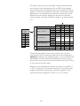
General Specifications
P series panelboard interiors are designed to accommodate top
or bottom feed. Regardless of which is specified for three-phase
panels, branch device poles are arranged with the uppermost
pole always on “A” phase, the second pole down always on “B”
phase, and the third pole down always on “C” phase.
As a standard configuration, branch breakers are mounted at
the top of the panel with “spaces” at the bottom, regardless of
the direction the panel is fed.
The panel design provides bracing up to 200,000 A. Keep in
mind that this is not the interrupting rating of the panel which
depends on the circuit breaker configuration.
Description
P1
480Y/277V AC Max.
Max. Voltage
250V DC Max.
1-phase, 2-wire
1-phase, 3-wire
System
3-phase, 3-wire
3-phase, 4-wire
Main Lugs
125-400A
Main Breaker 100-400A
Main Switch Not Applicable
Branch
15-100A
Ratings
P2
600V AC Max.
500V DC Max.
1-phase, 2-wire
1-phase, 3-wire
3-phase, 3-wire
3-phase, 4-wire
125-600A
100-600A
Not Applicable
P3
600V AC Max.
500V DC Max.
1-phase, 2-wire
1-phase, 3-wire
3-phase, 3-wire
3-phase, 4-wire
250-800A
225-600A
Not Applicable
15-225A
15-600A
P4
600V AC Max.
500V DC Max.
1-phase, 3-wire
3-phase, 3-wire
3-phase, 4-wire
P5
600V AC Max.
500V DC Max.
1-phase, 3-wire
3-phase, 3-wire
3-phase, 4-wire
400-1200A
400-800A
100-200A
15-600A Breaker
30-200A Fusible
800-1600A
800-1200A
400-1200A
15-1200A Breaker
30-1200A Fusible
Enclosure Options
Description
P1 P2 P3 P4 P5
Type 3R/12
● ● ● ● ●
Type 4, 4X
● ● ● ● ●
Drip Proof
● ● ● ● ●
Drip Proof Hood Only
● ● ● ● ●
Box
Sealed Box
● ● ● ● ●
Gasketed Trim
● ● ● ● ●
Wider Box
● ● ● ● ●
Deeper Box
- ● ● ● ●
Hinged Door
● ● ● ● ●
Door-in-Door Front
● ● ● ● ●
Common Front
● ● ● - Front
Split Door
● ● ● - Special Locks
● ● ● ● ●
Nameplate
● ● ● ● ●
● = Option, - = Not Available
49
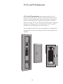
P1, P2, and P3 Panelboards
P1, P2, and P3 panelboards are grouped together in this
section because they are similar in construction and function.
Like all P series panelboards, these panels have symmetrical
interior mounting studs to eliminate the problem of upside
down mounting. P1, P2, and P3 panelboards feature concealed
fasteners and hinges with a flush door lock. P1, P2, and P3
panelboards are designed to be wall mounted.
The standard bussing for P series panelboards is temperature
rated aluminum with tin plating, but other bussing options are
available.
50
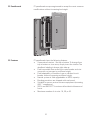
P1 Panelboards
P1 panelboards are pre-engineered to accept the most common
modifications without increasing box height.
P1 Features
P1 panelboards have the following features:
• Symmetrical interiors - No top or bottom. To change from
top to bottom or vice versa, simply invert the interior. The
deadfront labeling is always right-side up.
• Field convertible from main lug to main breaker and vice
versa with no increase in enclosure height.
• Field adaptability of feed-thru lugs or sub-feed circuit
breaker without increasing enclosure height.
• Neutral system is field upgradeable to 200% capacity.
• Bonding provisions are shipped with each panel.
• Suitable for use as service entrance equipment (assuming
NEC® compliance.)
• 250 V and 480 Y/277 V versions utilize identical boxes and
fronts.
• Maximum number of circuits: 18, 30, or 42.
51
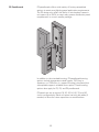
P2 Panelboards
P2 panelboards offer a wide variety of factory-assembled
options to meet most lighting panel application requirements.
The P2 design also offers the ability to mix breaker frames in
unit space up to 250 A to meet many power distribution panel
requirements in a much smaller package.
In addition to the standard bussing, P2 panelboard bussing
options include temperature rated copper, 750 A/sq. in.
aluminum, or 1000 A/sq. in. copper. Bussing is tin-plated, but
silver-plated copper is available as an option. These bussing
options also apply for P3, P4, and P5 panelboards.
P2 panels are set up around 18, 30, 42, 54, 66, 78, and 90
circuit configurations. Blank unit space can also be added, if
needed, to allow for future expansions or modifications.
52
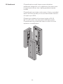
P3 Panelboards
P3 panelboards are small footprint power distribution
panelboards designed for use in applications that require more
or larger branch devices than a lighting panelboard typically
includes.
P3 panelboards can include a wide variety of factory assembled
options and have the ability to mix and match breaker frames in
unit space up to 250 A.
P3 panels are available with enclosure heights of 56, 62,
68, 74, or 80 inches. Like other power distribution panels,
P3 panelboards can include blank spaces to allow for future
expansions or modifications.
53
P4 and P5 Panelboards
P4 and P5 power panelboards are similar in design and
features, but vary in the ratings available. P4 panelboards have
a medium footprint to fit applications that require more or larger
branch devices and higher current ratings than lighting and
appliance panelboards can accommodate. P4 panelboards can
incorporate circuit breaker frames in unit space up to 800 A and
fusible switches up to 200 A.
P5 panelboards have the largest footprint of any P series panel,
allowing even higher rated main and branch devices, including
circuit breaker frames in unit space up to 1200 A and fusible
switches up to 1200 A.
54
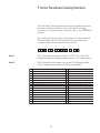
P Series Panelboard Catalog Numbers
The following P series panelboard catalog number description
provides summary information. For more detail including
information on circuit breaker selection, refer to the SPEEDFAX
catalog.
The catalog number provides a description of the panelboard.
There are eight parts to the standard P series panelboard
catalog number as the example below shows.
1
2
3
4
5
6
7
8
Part 1
Part 1 identifies the type of panel, P1, P2, P3, P4, or P5. The
sample panelboard catalog number shown is a P1 panelboard.
Part 2
Part 2 identifies the voltage and system. The following table
shows voltage and system configurations available.
C
208Y/120 3Ø4W Wye AC - All
R
415/240 3Ø4W Wye AC - All
E
480Y/277 3Ø4W Wye AC - All
S
440/250 3Ø4W Wye AC - All
D
240 3Ø3W Delta AC - All
L
600/347 3Ø4W Wye AC - All
F
480 3Ø3W Delta AC - P2, P3, P4, P5
T
230 3Ø3W Delta AC - All
G
600 3Ø3W Delta AC - P2, P3, P4, P5
W
380 3Ø3W Delta AC - P2, P3, P4, P5
I
347 3Ø3W Delta AC - P2, P3, P4, P5
1
24V DC 1 Pole Branches Only (3) - All
B
240/120 3Ø4W Delta BØ High Leg AC - All
2
24V DC 2 Pole Branches Only (3) - All
Q
240/120 3Ø4W Delta CØ High Leg AC - P2, P3, P4, P5 3
48 V DC 1 Pole Branches Only (3) - All
X
120/240 2Ø5W Single Neutral AC - P2, P3, P4, P5
4
48 V DC 2 Pole Branches Only (3) - All
A
120/240 1Ø3W Grounded Neutral AC (2) - All
5
125 V DC 1 Pole Branches Only (3) - All
H
120 1Ø2W Grounded Neutral AC (2) - All
N
125 V DC 2 Pole Branches Only - All
J
240 1Ø2W No Neutral AC (3) - All
O
125/250V DC 2 Pole Branches Only - All
Y
125 1Ø2W Grounded Neutal AC (2) - P2, P3, P4, P5
P
125/250V DC 2 & 3 Pole Branches - All
Z
500 2W DC - P2, P3, P4, P5
U
120V AC 3Ø3W - All
K
220/127 3Ø4W Wye AC - All
V
240V 3Ø3W Grounded BØ - All
M
380/220 3Ø4W Wye AC - All
55
The panelboard identified in the example is configured for a
208Y/120V, 3Ø4W power system. This indicates it is rated for a
208 volt wye-connected secondary. There are 208 volts phaseto-phase and 120 volts phase-to-neutral. It is a 3-phase (3Ø)
4-wire (4W) system.
A
208 Volts
120 Volts
B
120 Volts
208 Volts
N
120 Volts
208 Volts
C
Part 3
Part 3 indicates the number of circuits in a P1 or P2 type
panelboard. If the panelboard is a P3, P4, or P5 type, this
number represents the enclosure height in inches. In this
example, the panelboard is a P1 with 42 circuits.
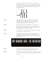
Part 4
Part 4 indicates whether the panelboard is a main breaker
(2-digit code varies for each different circuit breaker), main lug
(ML) or main switch (MS). In this example, FX indicates that the panelboard has an FXD6 main breaker.
Part 5
Part 5 indicates the panelboard current rating. In this example,
the panelboard is rated for 250 amps.
Part 6
Part 6 indicates the bus material. The following table shows
bus materials available. In this example, A indicates that the
panelboard has standard temperature rated aluminum bus bars
with tin plating.
Bus Code
Bus Material
Bus Plating
A
Temp. Rated Aluminum Tin Plated
B
750 A/sq. in. Aluminum Tin Plated
C
Temp. Rated Copper Tin Plated
E
Temp. Rated Copper Silver Plated
F
Temp. Rated Copper Tin Plated
G
1000 A/sq. in. Copper Tin Plated
H
1000 A/sq. in. Copper Tin Plated
● = Default for this bus type, N/A = Not Available
P1
P2
P3
P4
P5
●
●
●
●
●
N/A
●
●
●
●
●
●
●
N/A
N/A
N/A Optional Optional
●
●
N/A
●
●
●
●
N/A
●
●
Optional Optional
N/A Optional Optional
●
●
Part 7
Part 7 indicates whether feed location is from the top (T) or
bottom (B). In this example, the panelboard is top fed.
Part 8
Part 8 indicates whether the panelboard is surface mounted (S)
or flush mounted (F). In this example, the panelboard is surface
mounted.
56
You can minimize the potential for error when ordering
panelboards by making sure that you have the correct answers
to the following questions.
•
•
•
•
•
•
•
•
•
•
•
•
•
•
•
What is the power system (voltage, phases, number of
wires)?
What is the interrupting rating required for the panel?
Which NEMA type enclosure is required?
How many circuits are required for a P1 or P2 panel or
what will the enclosure height be for a P3, P4, or P5 panel?
Does the panelboard need to be suitable for service
entrance? Suitable for use on service entrance (SUSE)
labels are available, provided NEC® requirements are met.
What type of main will the panelboard require: main lug
only, main breaker, or main switch?
If the panelboard will be a main breaker or main switch
type, which main breaker or switch will be used?
What amperage rating is required for the panel?
What type of bussing is required?
Will the panelboard be top or bottom fed?
Will the panelboard be surface mounted or flush mounted?
Which branch device types and how many devices of each
type are needed.
Which accessories are needed?
What special modifications are needed?
When will the equipment be needed?
Review 6
1. ___ panelboards can be converted from main lug to
main breaker panels or vice versa in the field.
2. Standard bussing for P series panelboards is
temperature rated ________ with ________ plating.
3. P2 panelboards are set up around 18, 30, 42, 54, __, __,
and __ circuit configurations.
4. ___ and ___ panelboards can accept fusible switches as
main and branch devices.
5. Fusible switches used in P series panels are either
________ or HCP switches depending on the required
ratings.
6. A P series panelboard part number ending in TF
indicates that the panelboard is _____ fed and _______
mounted.
57
Quick-Spec Coordination Panelboards
Siemens Quick-Spec coordination panelboards provide
fusible solutions that make it simple and cost effective to
selectively coordinate a fused electrical distribution system.
These panelboards are designed to address the NEC® selective
coordination requirements. Selective coordination is a highly
desirable design consideration for many businesses because
selectively coordinated overcurrent protective devices help
avoid unnecessary blackouts that negatively affect business
assets and productivity. Siemens coordination panels are
especially designed for use in emergency systems, legally
required standby systems, healthcare essential electrical
systems, and critical operation power systems.
•
•
•
•
•
•
•
Voltage Ratings: 600VAC, 125VDC
Current Ratings: 30A, 60A, 100A, 200A, 225A, 400A
Main Options: Main lug only, fused main disconnect, nonfused main disconnect
Branch Circuit Positions: 18, 30, 42
Neutral Options: Unbonded and bonded 200A, 400A, 800A
Ground Options: Isolated and non-isolated
Enclosures: NEMA 1 and NEMA 3R
SCCPB Branch Disconnect
- 1-pole, 2-pole, 3-pole
versions available
- Current ratings: 15A, 20A,
30A, 40A, 50A, 60A, 70A
90A, 100A
CUBEFuse
- Finger-safe
- Dual element, time delay
- UL Class CF power fuse
with Class J fuse electrical
performance
- Indicating and non-indicating
versions available
Panelboard Short Circuit Current Ratings
M ain Lug O nly
H igh
S tandard
1
A C M ain O ptions
70-200A m ain disc.
225-400A m ain disc.
1
N o fuses or w ith C lass J F uses
1
N o fuses or w ith C lass J F uses
200k A
200k A
100k A
50kA
50kA
50kA
1. C lass J, t, or R K 1 fuses upstream , m ax. am ps = panel am ps
2. C U B E F use disconnect
58
D C M ain
S C C P _C F m ain
1
M ain lug only
2
disc. (60A )
20 0 k A
100kA
50kA
20k A
Additional Types of Panels and Cabinets
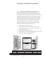
In addition to the P series and coordination panelboards
described in this course, Siemens also offers C1 and C2 column
type panelboards, lighting control panels, and telephone and
equipment cabinets.
Siemens C1 and C2 panelboards have a narrow width suitable
for column mounting. C1 panelboards are designed for a
250 VAC maximum supply and C2 panelboards are designed for
a 480Y/277 VAC maximum supply. Both panels are designed for
250 A mains and can be main breaker or main lug only.
C1/C2 Panelboard
Siemens lighting control panels have been designed to make
lighting control accessible for any building, whether the need
is as narrow as an on-off switch or as complicated as a fully
networked series of control panels sequencing on-off schemes
across many floors.
Siemens telephone and equipment cabinets are 5.75” deep,
20” or 24” wide, and vary in height from 23” to 59”. These
cabinets feature Siemens FAS latch fronts with concealed
hinges and fastening screws.
For additional information about these additional panels and
cabinets or other products described in this course, refer to the
SPEEDFAX catalog which is available on the Siemens web site.
59
Accessories
Accessories add to the performance of a panelboard or adapt
the panelboard for specific application requirements. Various
accessories are available for Siemens panelboards. The shunt
trip accessory described on this page is just one example of a
circuit breaker accessory. Refer to the SPEEDFAX catalog for a
complete listing.
Shunt Trip
Some accessories modify the circuit breaker. For example, it is
sometimes necessary to trip a breaker from a remote location.
This capability might be required for a variety of reasons, such
as when it is necessary to have a “panic button” that deenergizes machinery for safety reasons. One way to accomplish
this is to provide power to the machinery through a circuit
breaker equipped with a shunt trip accessory.
The shunt trip may be part of the main breaker, which will
shut off the entire panelboard, or part of a branch breaker. The
shunt trip device consists of a coil in series with a limit switch.
When the circuit breaker contacts are closed, the limit switch is
closed. Depressing a customer-supplied pushbutton energizes
the shunt trip coil, causing the breaker’s mechanical latch to
disengage the trip mechanism and opening the circuit breaker’s
contacts. When the circuit breaker’s contacts open, the limit
switch also opens, removing power from the shunt trip coil. As
with any trip, the breaker must be reset manually.
Limit Switch
Coil
Pushbutton
Customer Supply
60
Time Clocks
Tork, Sangamo or Paragon time clocks are available as an
external accessory for P1 panelboards and can be mounted
internally in P2, P3, P4, or P5 panelboards. Time clocks are
available in 1 or 2-pole, single or double throw devices, or 3pole, single throw. They are rated for a maximum of 277 volts.
A time clock can be used to turn a branch circuit or an entire
panelboard on and off at predetermined times. In the following
illustration, for example, a time clock connected to a panelboard
is used to turn outside lights for a small commercial building on
and off.
Tork Time Clock
Remote Control Switches
When an application requires remote control of loads, an ASCO
911 or 920 mechanically-held remote control switch or
Siemens LEN electrically-held contactor can be mounted in a
separate cabinet as a main disconnect.
61
TPS3 Transient Protection Systems
Many electrical devices and systems are susceptible to
damage from the high energy levels associated with electrical
surges caused by lightning or other electrical equipment. Any
component between the source of the surge and ground can
be damaged. Therefore, electrical systems aren’t complete
unless they incorporate surge protection. Surge protection
is best accomplished by stopping surges before they get in
through the application of hard-wired surge protection devices
(SPDs) installed at key electrical system surge entry points.
Siemens TPS3 SPDs are designed to the UL 1449 3rd edition
standard for hard-wired SPDs. TPS3 SPDs provide the highest
degree of safety while delivering some of the industry’s best
performance ratings. Siemens TPS3 family of commercial SPDs
share common performance parameters and are offered in two
configurations: integral SPDs (designed into our distribution
equipment) and external or wall-mounted SPDs.
TPS3 options are available for Siemens panelboards and other
distribution equipment. One example of an integral TPS3 SPD is
a P1 panelboard option that bolts directly to the panelboard bus
bars. Once installed, LEDs indicate that the device is working
and provide voltage and diagnostic monitoring. There is an
audible alarm and test button. Options include a surge counter
and a remote monitoring device.
P1 Panel with TPS3 SPD
TPS3 SPD
62
Power Meters
In today’s complex business climate, power monitoring systems
often require meters with a range of capabilities from basic
energy and power meters to advanced power quality meters
that can accumulate data from a variety of sources. In addition,
while small systems often need low-cost, stand-alone meters,
the growing demands for energy management and overall
monitoring of system performance mean that communication
with a variety of devices is increasingly important.
Fortunately, Siemens offers a complete range of energy, power,
and power quality metering products to meet virtually any
power monitoring system requirement. The Siemens SENTRON
PAC series of meters can be installed in P2, P3, P4, and P5
panelboards. In addition to the PAC series of meters, the
Siemens 9000 series of meters can be installed in P4 and P5
panelboards.
63
Embedded Sub-Metering
Solutions
In a world where tenant square footage is a premium in
commercial building designs, the area for electrical metering
is being drastically reduced. At the same time, contractor labor
costs for the installation of sub-metering systems continues to
increase.
To meet these sub-metering challenges, Siemens offers
proven cost-effective solutions for embedded metering and
monitoring. These solutions combine a fully-integrated metering
system factory installed in Siemens switchboards and P series
panelboards. Along with the required local or remote sub-billing
software, this provides a total sub-metering system.
When compared to the typical wall-mounted socket metering
installations, considerable savings in space, installation costs,
and data collection are realized with Siemens embedded
metering solutions.
The typical embedded metering design consists of:
• Rail mounted CTs that communicate to a central metering
unit mounted in unit space
• One 15 amp 3-pole breaker to power the units and obtain a
voltage reference
• Built-in communications
Rail-Mounted CTS
Rail-Mounted CTS
3.75”
Model MP636-EXTC
Embededed Metering
5.00”
P5 Panelboards with Model MP626EXTC Embedded Metering Solution
64
Review 7
1.
Siemens ________ panelboards provide fusible
solutions that make it simple and cost effective to
selectively coordinate a fused electrical distribution
system.
2. Siemens ________ and ________ panelboards have a
narrow width suitable for column mounting.
3. A ________ is a circuit breaker accessory designed to
trip a breaker from a remote location.
4. Siemens ________ family of commercial SPDs share
common performance parameters and are offered in
two configurations: integral SPDs (designed into our
distribution equipment) and external or wall-mounted
SPDs.
5. ________ are available as an external accessory for P1 panelboards or mounted internally in P2, P3, P4, or P5
panelboards when an application requires a panelboard
to be turned on and off at predetermined times.
6. ________ meters can be installed in P2, P3, P4, and P5
panelboards and a range of other Siemens meters can
be installed in P4 and P5 panelboards.
7.
When compared to the typical wall-mounted socket
metering installations, considerable savings in space,
installation costs, and data collection are realized with
Siemens ________.
65
Review Answers
Review 11) power distribution; 2) b; 3) 2008.
Review 21) can; 2) interior; 3) bus bar; 4) split; 5) dead front, trim.
Review 31) man breaker, main lug only, main switch;
2) horizontally, vertically; 3) lug only; 4) Feed-thru; 5) Sub-feed;
6) sub-feed.
Review 41) 277; 2) 120 A-N, 208 B-N, 120 C-N; 3) 6; 4) Bonding;
5) neutral.
Review 51) ground fault; 2) interrupting; 3) full; 4) UL.
Review 61) P1; 2) aluminum, tin; 3) 66, 78, 90; 4) P4, P5; 5) Vacu-Break;
6) top, flush.
Review 71) Quick-Spec coordination; 2) C1, C2; 3) shunt trip;
4) TPS3; 5) Time clocks; 6) SENTRON PAC;
7) embedded sub-metering solutions.
66
67
Final Exam
Before taking the final exam, it is recommended that you delete
the temporary internet files from your computer’s web browser.
For most versions of Internet Explorer, you can do this by
selecting Internet Options from the Tools menu and then
clicking on the Delete Files button. If you do not perform this
step, you may see a score of 0% after you submit your exam for
grading.
The final exam for this course is available online at
http://www.usa.siemens.com/step. This web page provides
links to all our quickSTEP online courses. To complete the final
exam for this course, click on the Basics of Panelboards link.
Next, move your mouse over to the left so that the navigation
bar pops out and select the Final Exam link. The final exam
page will appear.
After you complete the final exam, click on the Grade the
Exam button at the bottom of the page. Your score on the exam
will be displayed along with the questions that you missed.
If you score 70% or better on the exam, you will be given two
options for displaying and printing a certificate of completion.
The Print Certificate option allows you to display and print
the certificate without saving your score in our database and
the Save Score option allows you to save your score and
display and print your certificate. The Save Score option is
primarily intended for use by our distributors and Siemens
employees.
68