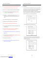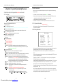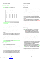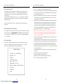
1
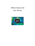
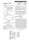
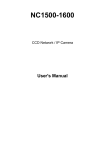
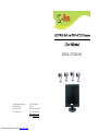
MODEL QT17DVR4C
Digital Peripheral Solutions Inc
8015 Ecrystal Drive
Anaheim, CA 92807
1-714-998-3440
PDF created with pdfFactory trial version www.pdffactory.com
Q-SEE Tech Support
IN USA
MONITOR:9am-5pm PST
TEL:1-899-998-3440
Email:[email protected]
Website:www.q-see.com
LCD WITH BUILT-IN DVR USER MANUAL
Alarm
Telecom
Network
interface
Others
LCD WITH BUILT-IN DVR USER MANUAL
Catalogue
Motion Detection
192 detecting areas can be set, and 16 levels sensitivity
adjustable
Alarm input
Four channels alarm(On/off value) input
independently
Alarm input solutions
Open/ close circuit optional
Important Safeguards… … … … … … … … … … … … … … … … … … … … e3
Chapter 1 Survey of Products… … …… … … … … … …… … … … … … … e4
Alarm Output
One channel linkage alarm output,one channel power
troubles alarm output,one channel other troubles alarm
output Relay on/off value:1A 120VAC/24VDC,
longtime on/off optional
Serial interface
RS485 signal, platform decoder can be connected outward.
2.1 Installing Manual for hard disc……………… ………… ………………e6
Serial interface
RS232 universal serial interface
2.2 Interfaces at Rear Panel …………………………………………………e6
Camera Specification … … … … … … … … … … … … … … … … … … … e1
1.1 Products Survey… … … … … … … … … … … … … … … … … … … … e4
1.2 Products Properties… … … … … … … … … … … … … … … … … … … e4
Chapter 2 System Installation… ………………… ………… ………………e6
Chapter 3 System Operating Manual… … … … … … … … … … … … … … e7
Network Interfaces
(optional)
RJ-45 10M/100M Ethernet interface
Network Transport
protocol
Support TCP/IP
Network Transportation
ways
Dial up access、ADSL、ISDN、LAN、CAN
Browsing Solutions
Software included
3.2.3 System on and off… …… … …… … … …… … …… … … …… … … e11
Clock
Built-in hard clock and permanent calendar
3.3 Properties Setup of the system…… … … …… … …… … … …… …… e11
Power
AC90 ~ 250
Power Consumption
Max:55W
3.3.3 Alarm Setup… … … … … … … … … … … … … … … … … … … … e1 3
Video System
Universal video system
3.3.4 Work Setup…………… ………… ………………… ………… ……e1 4
Max Brightness
300cd/m2
Max Contrast
450:1
3.3.7 System information…… … … … … … …… … … … … … …… … … e15
Response Time Tr/Tf
Tr+Tf=(16ms)
3.3.8 Basic parameter… … …… ……… … … …… ……… … … …… …… e16
Visual Angle
170 /150
Weight
22.3 ib
Di me ns ions
( W×H×D)
8.2×18.6×22.9
3.1 Instructions for front panel and remote control unit… … … … … … e7
3.1.1 Front panel…… … …… … … …… … …… … … …… … … … … … …e7
3.1.2 Remote Control Unit … … …… … … … … … …… … … …… … … e8
3.2 System on and off……… … ……… …… …… ……… … ……… … … e10
3.2.1 System Start… … … …… … … … … … …… … … … … … …… … … e10
3.2.2 System Login… … ……… … …… … ……… ……… …… …… … … e10
3.3.1 System Setup… … … ……… …… … ……… … …… …… …… … … e11
3.3.2 Thoroughfare parameter … … … … … …… … … … … … …… … … e13
3.3.5 Housing Setup… … …… … … … … … … … … … … … … …… … … e14
3.3.6 Net Parameter … … …… … … … … … …… … … … … … … … … … e15
3.3.9The "EXIT" key… … …… … …… … … …… … …… … … …… … … e17
3.4 Summary of other functions… … … … … … … … … … … … … … e17
3.4.1 Analog function… … … … … … … … … … … … … … … … … … … e17
4.1 All Record … … … … … … … … … … … … … … … … … … … … … e17
4.2 Log … … … … … … … … … … … … … … … … … … … … … … … … e18
4.3 Video Record Status………… …… … ……………… …… …… …… e19
4.4 Hard Disk Status … … …… … …… … … …… … …… … … …… … … e20
4.5 Exit…… …… …………… ………… ………………… ………… …… e21
Main specifications for the system … … … … … … … … … … … … … … e22
-e23-
PDF created with pdfFactory trial version www.pdffactory.com
LCD WITH BUILT-IN DVR USER MANUAL
LCD WITH BUILT-IN DVR USER MANUAL
Main specific ations for the system
Camera Specification
17 '' 4:3 TFT/LCD
Tube
Camera Features
1/3" Color CCD
Video
Resolution 420 TV Lines
Weatherproof
Video Input
Four Channels Independent Input 1.0Vp-p, 75 Ω BNC
Video Output
Two Channels PAL/NTSC output,1.0Vp-p, 75 Ω BNC,
Multiple Video Signal
One Channel VGA display interface output
Video Display
Any Single picture, built-in quad display
Video Standard
PAL system 25 frames/second CCIR625 lines 50 fields
NTSC system 30 frames/second CCIR625 lines 50 fields
System Resources
Real time recording resources, one or four channels play
backward can be realized at the same time;one or four
channels monitoring, network real time monitoring
Audio Input
Two channels independent input 600Ω RCA
Audio Output
Two channels independent output 600 Ω RCA
Basic Output Gain
1.0-2.2V
Distortion Plus Noise
≤-30dB
Recording Solutions
Volume and Image are Synchronized
Audio Compression
MPEG-1 LAYER2
Operating Language
English
Operating Interface
OSD menu
Password control
Password for operators and administrators
Image Compression
MPEG-4 Changeable bit streams/ Fixed bit streams
Image format
Single picture:HD1 format
(704×576 pixels)
Video code rate
6.25-250Kbyte/s
12 IRLEDS for Night vision
Audio
System
Video volume taken in H.D. 22.5M-900Mbyte/hour
Digital
Processing
Play backward 352×288 Pixels,real time monitoring
Resolution
and
704×576 pixels,VGA output 704×576 pixels
Storage
-e1-
PDF created with pdfFactory trial version www.pdffactory.com
Video current standard
ISO14496
Audio current standard
ISO11172
Audio code rate
24Kbyte/s
Audio volume taken in H.D
86.4Mbyte/hour
Internal Storage
One IDE hard disk, support H.D. with big volume of
200G or more
Image quality
8 levels for adjusting:1-8 levels
Date read and write way
Full duplex
-e22-
LCD WITH BUILT-IN DVR USER MANUAL
LCD WITH BUILT-IN DVR USER MANUAL
HDD Status
HDD
Status
Capacity
Free_Space
1
Video Record
160G
128,125MB
2
Sleep
040G
039,000MB
3
None
000G
000,000MB
4
None
000G
000,000MB
Return
will enter into inquiry machine information interface, this interface will display current software
version and MAC address information.
CAUTION
RISK OF ELECTRIC SHOCK
DO NOT OPEN
CAUTION:TO REDUCE THE RISK OF ELECTRIC
SHOCK,DO NOT REMOVE THE BACK.
NO USER SERVICEABLE PARTS
INSIDE. REFER SERVICING TO
QUALIFIED SERVICE PERSONNEL
Search Menu
All Record
Graphic Symbol Explanation
Log
Record Status
HDD Status
Machine Info
The lightning flash with arrowhead symbol, within an equilateral triangle, is intended to alert the
Exit
user to the presence of uninsulated 'dangerous coltage' within the product's enclosure that may
be of sufficient magnitude to constitute a risk of electric shock to persons.
Version: 6214C-A-01.000
MAC Address: 000.111.111.111.110
The exclamation point withinan equilateral triangle is intended to alert the user to the presence
of important operating and maintenance (servicing) instructions in the literature accompanying
the appliance
Return
Software Version: display machine type, software type, panel information and version information;
MAC address: pressing [EN TER] key or inputting digit according to need can setup.
Note: only super user can hold changing MAC address authority;
Warning - To Prevent Fire Or Shock Hazard, Do Not Expose This Monitor
To Rain Or Moisture.
This Product Must Be Earthed.
4.5 Exit
Moving cursor to this selection item, and pressing [ENTER] key to confirm will exit to inquiry menu,
Product Specification Is Subject To Change Without Notice.
and exit to monitoring image.
-e21-
PDF created with pdfFactory trial version www.pdffactory.com
-e2-
LCD WITH BUILT-IN DVR USER MANUAL
LCD WITH BUILT-IN DVR USER MANUAL
IMPORTANT SAFEGUARDS
4.3 Video Record Status.
Caution
This equipment is to be opened by ONLY a qualified serviceperson. There are no user
serviceable parts inside. Opening this equipment may expose to dangerous voltage and
other risks. Incorrect re-assembly of this equipment may result in electric shock.
Search Menu
All Record
Log
Record Status
1. Read lnstructions:
All the safety and operating instructions should be read before the appliance is operated.
2. Follow lnstructions:
All operating and use instructions should be followed.
3. Cleaning:
Unplug this monitor from the wall outlet before cleaning. Do not use liquid cleaners
or aerosol cleaners. Use a damp cloth for cleaning.
HDD Status
Machine Info
Exit
Channel St atus
4. Water and Moisture: Do not use this monitor near water, for example, near a bathtub, wash bowl, kitchen
sink, laundry tub, in a wet basement, swimming pool, or any other wet surface.
5. Accessories:
Do not place this monitor on an uneven surface. The monitor may fall, causing
serious injury to a child or adult, and serious damage to the appliance. Use only
with a cart, stand, tripod, bracket, or table recommended by supplier, or sold
with the monitor.
6. Ventilation:
Slots and openings in the cabinet are provided for ventilation to ensure reliable
operation of the monitor and to protect it from overheating, and these openings
should never be blocked by placing the monitor on a bed, sofa, rug, or other
similar surfaces. This monitor should never be placed near or over a radiator or
heat register. This monitor should not be placed in a built-in installation such as
a bookcase or rack unless proper ventilation is provided or supplier instructions
have been adhered to.
7. Object and Liquid
Entry:
8. Repair(Servicing):
Never push objects of any kind into this monitor through openings as they may
touch dangerous voltage points or short-out pa rts that would result in a fire or
electric shock. Never spill liquid of any kind on the monitor.
Do not attempt to repair this monitor yourself as opening or removing covers may
expose you to dangerous voltage or other hazards. Refer to qualified service personnel.
M ode
Status
Q F rame
F _Pic
Idle
1
25
close
Please consult the manufacturer for the replacement parts.
10. Safety Check:
Upon completion of any service or repair to this monitor, ask the service
technician to perform safety checks to determine that the monitor is in proper
operating condition.
1) Mode: Displays current image video recording mode, : Single mode, dual mode, quad image.
2) Status: video record/sleep two status
3) Image quality: display video record data image quality
4) Frame rate: display video record frame rate information
5) Alarm: setting alarm/cancel alarm two status, start alarm video record, will be setting alarm,
instead, will be cancel alarm
6) Motion detection: turn on/ turn off.
4.4 Hard Disk Status
Moving cursor to [Hard Disk Status] item, and pressing [ENTER] key will enter into inquiry
hard disk status interface, this interface will display current hard disk status, including hard
disk's space and free space.
All Record
Log
Record Status
HDD Status
Machine Info
11. Retain Instructions: The safety and operating instructions should be retained for future reference.
-e3-
PDF created with pdfFactory trial version www.pdffactory.com
clo se
Ret urn
Search Menu
9. Replacement Parts:
Alarm Moti on Det ect
Exit
-e20-
LCD WITH BUILT-IN DVR USER MANUAL
LCD WITH BUILT-IN DVR USER MANUAL
4.2 Log
Chapter 1 Survey of Products
Moving cursor to [LOG] item, and pressing [ENTER] key will enter into inquiry log interface
1. 1 Products Survey
Input date and type of the log
Type: All Event
Date : 2006--04--28--23--30
Start
Return
The equipment is a kind of small channels digital monitoring products which is specially designed for
security industry. It adopts the embedded processor and operating system and also integrates the
most advanced technologies in IT field, such as using MPEG-4 video and audio compressing /
decompressing, recording by hard disk with big volume, TCP/IP network and other technologies.
The code solidity in FLASH has changed the traditional mode of Monitor with DVR. It integrates
the Monitor with DVR instead ,which not only is more convenient for users to operate but also
makes the system more stable and convenient for maintenance.
Format: includes all events recording mode, alarm mode, motion detection and operation mode;
According to the need select check time and click start.
1. All Events: Record all system operation and alarm record;
2. Alarm Events: [ENTER] key will enter into check alarm log interface. This interface will display the
1. 2 Products Prope rties
l
Adopting the high-speed embedded micro-controller and also real time operating system, the
system has a super-high stability, high durability, without crash phenomenon and also easy for
maintenance.
l
Easy Installation and use .
l
Two levels of password protection from administrator and user guarantees the safety of the
system.
l
The system adopts the OSD graphical interfaces, which is more convenient for users
to follow .
l
The video compression adopts the pure hardware MPEG-4 Changeable stream or MPEG-4 fixed
stream,supporting the HD1 and CIF resolution recording in each channel, the frame rate for
recording is adjustable, with high sharpness but super-low hard disk space used.
l
Adopts FAT32 format to store, and can take one unit IDE hard disc upto 300GB.
l
For channels video input, two channels video output, one channel VGA output; Two channels
audio input, two channels audio output and one USB Port.
l
Three channels alarm input, one channel linkage alarm output and one channel troubles
alarm output.
l
Real time monitoring and playback in single picture mode, dual mode or quad mode
l
The system supports turning on and off the machine automatically. In case of power outage,
it resumes recording automatically once the power is restored. Alarm will go off automatically
when no video signal is being received. This eliminates the need to monitor the system frequently.
alarm situation that happened recently. Moving cursor to "up" and "down" place, and pressing
[ENTER] key to turn over page. Alarm log will record exact alarm time in case of Video Loss/Place
Setting/Password Error.
Log Search: All Event
04--02--15--30,
Video Loss 1
04--02--15--30,
Place Alarm
04--02--15--30,
Video Loss 2
Return
Page Up
Page Down
Motion Detection: Temporarily no record, same as in alarm mode;
Operation Affair: moving cursor to [Operation Log] item, and pressing [ENTER] key into inquiry
operation log interface. This interface display recently happen operation situation:
Log Search: Operation Affair
04--02--15--30
Manual Video Record
04--02--15--30
Restart
04--02--15--31
Pan/Tilt Control
04--02--15--35
Parameter Change
Return
Page Up
Page Down
Moving cursor to "up" and "down" place, and pressing [ENTER] key to turn over page, so can check
its record page by page.
-e19-
PDF created with pdfFactory trial version www.pdffactory.com
-e4-
LCD WITH BUILT-IN DVR USER MANUAL
LCD WITH BUILT-IN DVR USER MANUAL
l Manual Recording, time recording, alarm recording, motion detection recording saves the hard
disc space ensuring effective usage of the hard drive space for longer periods of time.
l Motion detection recording function, can setup more than 192 detecting areas independently.
l The system supports pre-alarm recording and alarm prolong recording guarantees, which
guarantees the integrity of alarm recording equipment.
l Equipped With×2、×4times fast forward/ fast backward play functions and ×1/2、×1/4、
×1/8 times speed slow motion backward play, pause and frame play and others play control
functions.
l The system supports PAL/NTSC systems,hence this system can be used universally.
4.1 All Record
Moving cursor to [All Record] item, and pressing [ENTER] key will enter into All Record interface:
Mode: moving cursor upon this selection item, and pressing [ENTER] key can select different video
record format to inquiry (All video record/Timing video record/Alarm Video record)
Date Time: Move cursor to this selection , and press [ENTER] key or directly input the date and time,
based on the recording date and time you want to playback; No press [START] to see the available
recording for that duration. If there is no record found, it will say "No Record"
2 006--04 --0 2 All Rec ord
01
02
03
04
05
06
07
08
09
10
11
12
13
14
15
16
17
18
19
20
21
22
23
24
25
26
27
28
29
30
31
UP DN
N o Recor d
R etur n
l Brightness, contrast, Color and Tint can be setup individually for each channel.
l Perfect alarm log and operating log facilitates convenient analysis and searching .
When selected date has video record, it will display below interface
l RJ-45 universal network telecom interface, network transmitting ways include ADSL、ISDN、
LAN and CAN and so on;
l T he included client software facilitates the long-distance monitoring and playback on net,
and supports TCP/IP、UDP/IP and many other net transport protocols.
l RS-485 interface equipped with the system can be used to control P/T/Z cameras with various
decode protocols .
l VGA output has 720×480、1280×720 and 1920×1080 Resolution modes, better quality picture
could be attained by adopting progressive scanning.
2006--04--02 All Record
01
02
03
04
05
06
07
08
09
10
11
12
13
14
15
16
17
18
19
20
21
22
UP DN 23
24
25
26
27
28
29
30
31
1 00000000 08: 00 - 09: 00 A 25
1 00000000 09: 00 - 10: 00 R 25
1 00000000 10: 00 - 11: 00 R 25
Return
You can also scroll through other dates during the month to view the recording. If the date is in
yellow color it means that there is a recording for that particular day. Press [ENTER] to view
the available recording for that day.
l Supporting IDE hard disk material backup.
l Equipped with USB2.0 interface to the system,which could be used for backup to your PC or
laptop directly from the DVR hard drive .
2006--04--02 All Record
01
02
03
04
05
06
07
08
09
10
11
12
13
14
15
16
17
18
19
20
21
22
UP DN 23
24
25
26
27
28
29
30
31
1 00000000 08: 00 - 09: 00 A 25
1 00000000 09: 00 - 10: 00 R 25
1 00000000 10: 00 - 11: 00 R 25
Return
-e5-
PDF created with pdfFactory trial version www.pdffactory.com
-e18-
LCD WITH BUILT-IN DVR USER MANUAL
LCD WITH BUILT-IN DVR USER MANUAL
CBR: Denotes fixed code flow's coding format, this coding format shows, image quality is
invariable, but image quality can change according to moving object's scale inside, the larger the
Chapter 2
System Installation
moving object occupied in image's scale, the worse the image quality
Message Sound Switch: When setting is turn on, hard disk error and password input error,
machine buzzer will sound.
Language setting: Moving cursor to this item and pressing [ENTER] key can switch Chinese and
English interface.
Peak segment setting: Moving cursor to this item and pressing [ENTER] key can enter into
2.1 Hard Driv e Installation
Note: please set the hard disc to "Master"mode when connecting to the DVR.
2.2 Interfac es on Back Panel
corresponding interface.
Packing time: Moving cursor upon this item and pressing [ENTER] key to adjust, can select
30, 45 and 60 minutes packing time.
USB 2.0 setting: Moving cursor upon this item and pressing [ENTER] key to confirm will turn
on USB interface
Instruction: After turning on USE 2.0 setting you can connect to PC computer (PC computer
only need USB 2.0 interface), and backup the files on your PC. Once you select USB2.0 function
[Return], machine will restart.
3.3.9The " EXIT " key
Move the mouse to the topic of "EXIT" and press enter to save settings and back to the setting menu and
return the monitor TV screen.
VIDEO IN:1~4 Video Input
3.4 Summary of other functions
VIDEO OUT:1~2 Video Output
3.4.1 Analog function
USB:One Channel USB terminal input
When the system is in the single screen mode, the user can adjust the picture quality
Brightness: press the analog key on the remote control, the screen will show "Brightness" on
NET:One Channel NET terminal Input
AUDIO IN:One Channel left/ One Channel right audio input
the top right hand corner . Press "-" or "+" to adjust the brightness as desired.
AUDIO OUT:One Channel left/ one Channel right audio output
Saturation: Press the "Analog" key for second time and "Saturation" appears on the top right
VGA:One Channel VGA terminal input
hand corner. Press "-" or "+" to adjust the saturation as desired.
Contrast degree: Press the "Analog" key for third time and "Contrast" appears on the top
right hand corner. Press "-" or "+" to adjust the contrast as desired.
Hue: Press the "Analog" key for the fourth time and "Hue" appears on the top right hand
corner. Press "-" or "+" to adjust the color as desired.
After running system, by pressing [Check] key will enter into inquiry menu, screen will display
main menu, pressing direction key to select wanted check item, and press [ENTER] key enter
into this item.
ALARM
① 、Alarm output 1
② 、Alarm output 2
③ 、Ground wire
④ 、Alarm input 1
2
3
⑤ 、Alarm input 2
Search Menu
⑥ 、Alarm input 3
All Record
⑦ 、Ground wire
Log
⑧ 、485B
Record Status
1
⑨ 、485A
HDD Status
Machine Info
Exit
-e17-
PDF created with pdfFactory trial version www.pdffactory.com
-e6-
4
5
6
7
8
9
LCD WITH BUILT-IN DVR USER MANUAL
LCD WITH BUILT-IN DVR USER MANUAL
Chapter 3 System Operating Manual
3.3.6 Net Parameter
Move the cursor to the net parameter and press enter to get into the system's net interface setting.
3. 1 Instructions for front panel and remote control unit
See picture below:
3.1.1 Front Panel
a). IP address: Press enter or manually type numbers on the IP address line.
POWER
H.D.
ALA RM
b). Sub-net Mask: Moving cursor upon this selection item and pressing [ENTER] key or input
NET
IR
number directly, set host IP address correctly according to host local LAN
c). Default Gateway: setting according to IP address
d). Bandwith: This feature can be used to set the speed of transfer of data over the network
Buttons on front panel and their functions:
① Indicating light area
NET:Indicating light for network
When network connection is ok, it displays green, and when data is transferring it flashes.
ALARM:Indicating light for alarm
The alarm light will be on once the alarm is started( no matter what kind of alarm it is for)
H.D. :Indicating light for Hard Disk
The light turns on when Hard Disk reads and writes the data.
POWER :Indicating light for power
The power is on if the light turns red;
② Buttons area
Menu operating buttons
:UP Directional button;
:Down Directional button;
:Left Directional button;
:R ight Directional button
【 】button:for confirmation,choosing the menu items, and press this button to enter into
the selected sub-menu;Pressing this button can display the real time of the system
when playing back the recording;
Functional Buttons Area
【 】Button:Main Menu, used for setting each parameters of the system.
【 】Button:Play the existing recording on the hard drive;
【 】Button:Checking the menu buttons, used for checking recorded information on the hard disc;
【 】Button:Exit button,exit from the current operating menu to last selected menu;
【 】Button: Recording button,four channels manual recording can be started at the same time
when the screen is in built-in quad mode , dual views manual recording can be started
when the screen is under two channels surveillance state; Single channel Manual
recording can be started when the monitor is under single channel surveillance state
【 】Button:For stopping the recording button and the manual recording;
【 】Button:Fast Rewind button, at speed of ×2 and ×4 times;
【 】Button:fast forward button,Play fast forward of the recorded picture at speed of ×2
and ×4 times;
【 】Button:Press this button continuously to see the picture frame by frame ;
【 】Button:Used for switching between built-in quad, dual and single picture mode;
in the following order :
Channel 1 Channel 2 Channel 3 Channel 4 Dual Views (Channel 1Channel 2) Dual Views (Channel 3- Channel 4) Built-in quad Channel1
-e7-
PDF created with pdfFactory trial version www.pdffactory.com
3.3.7 System Information (need screen shot)
Moving cursor over [System information] and pressing [ENTER] key enter into system
information setting interface.
3.3.8 Basic parameter
Basic Settings
Record Settings:
Buiz Settings:
Setup
Close
Language Settings:
English
Fastigium Settings:
Recordbag Settings:
Open
30 minute
USB Settings:
Video Spot Settings:
Setup
05 Second
Moving cursor to [Basic parameter] item (bottom color of character change to white means being
selected) and pressing [ENTER] key enter to this item selection setting interface:
After entering into sub-menu, move cursor up and down to scroll through the sub
menu.
Video recording parameter setting: Moving cursor upon this item and pressing [ENTER] key takes
you to the corresponding interface.
Image quality: Divided into "1-8" different parameters. Press [Enter] to change this parameter
The smaller the digit, the better the image quality.
Frames per second: When system has been set to PAL format, it can divide into "25、12、06" three
ranks, when system has been set to NTSC format, it can divide into "30、15、08、"three ranks.
Moving cursor upon this item and pressing [ENTER] key will change its parameter.
Format: Moving cursor upon this item and pressing [ENTER] key can switch system's video record
coding format: VBR、CBR.
VBR: Denotes changeable code flow's coding format, this coding format shows, image quality is
invariable, but data code flow's size can change according to moving object's scale inside, the larger
the moving object occupied in image's scale, the larger the code flow.
-e16-
LCD WITH BUILT-IN DVR USER MANUAL
3.3.5 Housing setting
LCD WITH BUILT-IN DVR USER MANUAL
3. 1.2 Re mote Control Unit
Moving cursor upon [Pan/Tilt setting] and pressing [ENTER] key can enter into quad channel
L O GIN/ L OCK
Pan/Tilt port setting interface
PO WE R ON
PL AYBA C K
A. Channel: Denotes system's channel number.
B. Protocol: Denotes the communication protocol between system and decoder. Moving cursor
1
2
3
4
5
6
7
8
QUAD
P A RAMET E R
9
ANAL O G
+
0
ZOOM +
ZO OM-
to this selection item and pressing [ENTER] key can make selection among different protocol
(Pe1co-D/P/09-15/Dscp/FastDome/PIH1016-1017/JECFastD/RM110/Neocam) Selected
FO CUS+
FO CUSEXIT
AU TO
protocol must match to the protocol of decoder, only can it control front equipment correctly.
C. Baud rate: Denotes communication speed between system and decoder. Moving cursor to this
item selection and pressing [ENTER] key can make selection among different baud rate
REC ALL P R ESET
SW ITC H
PLAY
SLOW
CF
F WD
REV
NET
R ECOR D
ST OP
F1
F2
SE T UP
F3
F4
(1200/2400/4800/9600), selected baud rate must match decoder's baud rate, only can it control
front equipment correctly.
D. Pan/Tilt code: Moving cursor upon this selection item and pressing [ENTER] can make
selection among different Pan/Tilt serial number (01-63), system's 01 code number match
to decoder's first address code, that is address code "01"
E. After setting up all item selection, move cursor to [RETURN] and press [ENTER] key will
return toprevious menu, and save Pan/Tilt parameter setting.
Attention: Pan/Tilt protocol, baud rate, Pan/Tilt serial number three items must be in
accordance with outer Pan/Tilt (quick ball) setting parameter.
Pan /Tilt operation: After setting Pan/Tilt parameter correctly, press [F2] key on remote
control under single monitoring state, the top left corner of screen will display "Pan/Tilt control"
character, temporarily, we can operate this channel's Pan/Tilt by using press [F2] key on remote
control and panel.
【 】、【 】Key: Lens up and down motion, display character: up and down;
【 】、【 】Key: Lens left and right motion, display character: Pan/Tilt left and right;
【Change times +】、【Change time -】Key: Adjust image far and near extent, display character:
Change times + and change times -;
【Aperture +】、【Aperture -】Key: Adjust image bright and dark extent, display character:
Aperture + and aperture -;
【Focus +】、【Focus -】Key: Adjust image clarity extent, display character: Focus + and focus -;
【Automatic】Key: signifies automatic control, display character: Automatic
【Transfer】Key: Pan/Tilt transfer control, display character: transfer 00, back key;
【Pre-set】Key: Pan/Tilt preset control, display character: preset 00, back key.
【Washer switch/Light】Key: Washer switch and light assistant switch control, display character:
Washer switch;
Pressing [F2] and [Pan/Tilt] once more will exit Pan/Tilt operation, and return to single image
monitoring state; Switch monitoring image and pressing [F2] key can enter into another channel
Pan/Tilt operation.
Warning 1: When operating Pan/Tilt function, system can't startup manual video recording
function.
Warning 2: When operating Pan/Tilt function, once system startup video record (timing or
alarm startup), temporarily can't affect Pan/Tilt operation.
Troubleshooting: When Pan/Tilt doesn't operate normally, Please check RS-485 (see "Alarm
Port lead line definition") and Pan/Tilt parameter
-e15-
PDF created with pdfFactory trial version www.pdffactory.com
Buttons on Remote Control Unit and their functions:
① Digital Buttons Area
【0-9】Button:Digital buttons,used for using digit input or video switch,when under the
built-in quad state, press 1、2、3、4 digit buttons mean to switch the picture
output to the first, second, third and forth channel video single picture;
【+】、【-】Button:Adjusting various parameters;
② Menu Operating Buttons Area
: UP Directional button;
:DOWN Directional button;
: LEFT Directional button;
:RIGHT Directional button;
【ENTER】button:for confirmation,choosing the menu items, and press this button to enter
into the selected sub-menu;Pressing this button can display the real time
of the system when playing back the recording;
③ Platform control function buttons
【ZOOM+】、【ZOOM-】Button:Adjust the distance of the picture;
【APERTURE+】、【APERTURE-】Button:Adjust the brightness of the picture;
【FOCUS+】、【FOCUS-】Button:Adjust the sharpness of the picture;
【AUTO】Button: Control automatically;
【RECALL】Button: standby button in control of platform;
【PRESET】Button: Preset control on platform, standby button;
【SWITCH】Button: control on some assistant switch;
④ Play function buttons
【PLAY】Button:Play the the recording on the hard drive;
【SLOW】Button:Play the images slowly,at speed of ×1/2、×1/4、×1/8 times,or press
【play】button to return to normal playing speed;
【PAUSE/SETP】Button:Press one time to Pause the picture ,and then press continuously,
picture will be displayed frame by frame, press 【Play】button to
return to normal speed of playing.
【FWD】Button:Play fast forward of the playback picture,at the speed of×2、×4 times,press
【Play】Button to return to the normal speed of playing;
【REV】Button:Play fast backward of the playback pictures, at speed of×2、×4 times,press
【Play】Button to return the normal speed of playing;
-e8-
LCD WITH BUILT-IN DVR USER MANUAL
LCD WITH BUILT-IN DVR USER MANUAL
⑤ Other function buttons
【POWER/ON】Button:for turning on and off the machine(Standby and start);
【LOG IN/LOCK】Button:get the operating rights, to type in the password and lock operation;
【PLAYBACK】Button:For reviewing the recording, log, state of hard disc,information of
software edition and so on;
【QUAD】Button:For switching pictures between built-in quad, dual views and single picture;
Order of Display : Channel1 Channel 2 Channel 3 Channel 4 Dual views
(Channel 1-Channel 2) Dual views (Channel3-Channel 4) Built-in
quad Channel 1
【ANALOG】Button:display the brightness, contrast, colour and tint, adjusting its parameters
together with the adjustment of【+】 、 【-】 button(This operation need
to be performed only when under single picture mode and this channel should be
under non-recording state);
【EXIT】Button:Exit button, exit from the operating menu to last selected menu directly.
【CF】Button:Enter into the standby menu for recording material, copy the material in hard disk
to the outward connected memory device(hardware with CF card connector
is needed)
【LANGUAGE】Button:Enter into '' language selection ''menu directly to setup the language.
【NET】Button:Standby button;
【RECORD】Button:Start the manual recording in single, dual or quad mode
【STOP】Button:Stop the manual recording(operating way is the same with that for【recording】
button);
【SETUP】Button:When login the system normally, press this function button to enter into the
menu setting of the system;
【F1】Button:For pick time play on the recorded pictures;
【F2】Button:Press this button to enter into the control menu of platform when under the single
channel picture.
Press left, right, up and down buttons can do recording adjustment to platform camera;
Press【Zoom+】、【Zoom-】Button:Adjust the distance of the picture;
Press【Aperture+】、【Aperture-】Button:Adjust the brightness of the picture;
Press【Focus+】、【Focus-】Button:Adjust the sharpness of the picture;
Press【Assistant】Button:Control on some assistant switch;
Press【Auto】Button:Control automatically;
Press【Event】Button:standby button in control of platform;
Press【Preset】Button:Preset control on platform, standby button;
Press again the 【F2】button or 【Exit】 button to exit the
setting for the platform control menu;
【F3】Button:Standby Button.
【F4】Button:switch between the monitor and VGA output;
Operating ways:Press 【F4】button in remote control unit to switch between
output of monitor and output of display when under monitoring. Its order is: output
of monitor VGA 1 VGA 2 VGA 3;There are three states for VGA output,
which can be adopted for different VGA standard.
-e9-
PDF created with pdfFactory trial version www.pdffactory.com
e). Delay the alarm output: Under the alarm recording mode, the system is communicating the
alarm output signal with the alarm output end point automatically after moving the testing
signal has received the alarm signal from the I/O. Delay the alarm output means delaying the
continuous time of the alarm's output signal.
f). I/O alarm output: Two choices are open or close. When system has received the alarm signal
from the I/O, it will alarm from the output end point. When system has not received the alarm
signal from the I/O, it will not alarm from the output end point.
g).Motion alarm output the same as the above.
If you do not do the setting for each channel, it means invalid channel and that channel can't record
video, you can till see the image under monitoring if the channel has image signal But the system will
not prompt the alarm message if the image signal of this TV screen is lost.
3.3.4 Work Setup
Record Setup
Channel
1
Schedule
Setup
Area-Set
Setup
2
Setup
Setup
3
4
Setup
Setup
Setup
Setup
Return
The content of the Work Set order includes scheduling recording for each channel and the setting
up of area for each channel for motion detection.
The specific operation of each function is given below:
A. Setting the recording time: Press Setup for each channel under "Schedule" to setup the day
(Mon-Sun), Time of recording Ist Segment, recording mode(Time, Alarm or motion) Time
of recording 2nd Segment, type of recording mode. There are 2 segments of recording to
accommodate the change in date. For example, if you start recording at 11:30pm on Monday,
the Ist set will be 11:30pm to 11:59pm and the second set will be 12:00am to 11:
B. Survey area setting: The picture above is showing that the whole screen is composed of
192 small areas. The blue color represents the area that has not been selected; the been purple
represents the area that has been selected; blue color t he operating method is once getting into
the setting interface; the purple small square will be flickering between two colors alternatively
which are purple and blue .
If you press [Enter] The small purple square will change its color to two colors which are purple
and blue and it will be flickering alternatively.
-e14-
LCD WITH BUILT-IN DVR USER MANUAL
LCD WITH BUILT-IN DVR USER MANUAL
3. 2 System on/off
3.3.2 CHANNEL SETU P
3. 2.1 Sy stem Start
Channel setup setting includes channel name, screen display, clock insert,
TV screen cover, etc
Channel Setup
CH
Title
CH Name
Time InSert
Mask
CH View
1
Open
Down
Close
Open
2
Open
Down
Close
Open
3
Open
Down
Close
Open
4
Open
Down
Close
Open
Return
a). Channel: Enter the channel number. If it has a X symbol in front of the channel number code,
it indicates invalid channel.
Note: For each channel, it means the channel can't record video. However, you can still see the
channel image under monitoring if the channel has image signal. But, the system will not prompt
the alarm message if the image signal of this TV screen has lost.
b). Title : Name of the channel. Enter the title of the camera location. Move the cursor to this topic
and press enter and enter the channel title. When you have finished, press enter.
c). Screen Display: Two choices are switch on or switch off. If switch on is selected , it will show the
channel title while monitoring. If selecting switch off, it will not show channel title while
monitoring.
d). Time Insert: There are three choices for users, up, down or close. Press Enter to make your selection.
When option up is selected, the time will be displayed on top of the screen, when option Down is
selected, the time will be displayed at the bottom of the screen. If the option Closed is selected,
the time will not be displayed on the screen.
e). Mask: Two choices for users are switch on or switch off. You can press enter for any changes.
TV mask used for covering the part of channel which is not to be recorded.
f). Channel View: Two choices for users are open or close. Open keeps the channel open for viewing
and close blocks the image from viewing.
3.3.3 Alarm Setting
a). Terminal: 1, 2, 3, 4 respectively represent 4 outer I/O alarm input ports.
b). Open:Two choices are open or close. Open indicates the system has received the input alarm signals
from the I/O end points. Close indicates the system has not received the input alarm signals.
C). inputting way: Two choices are(close/short)closed circuit and open circuit. Users have the
option to turn on /off alarm for each channel
d). Delay alarm recording: Under the alarm recording condition, the system receives the alarm signal
from I/O. The system recording video is according to the time length which the user has already
When supplying power to DVR normally, the system enters into stand-by state(the indicating
light of the power-red led is on permanently)。
When press the【on/off】button in the remote control unit,the system is started,pictures
displayed in the screen are built-in quad images,the digit showed in each picture means its video
input channel No. the real time will be displayed at the top center of the screen.
Note: If time recording has been setup in this machine(or at high peak period),
and power is just connected during this period, then the machine will start and enter
into multi-pictures state directly without needing to press【on/off】button again to start
the machine.
If there is no display of video input channel No in the screen and the real time for the
system, please press【ENTER】 button on the remote control unit or panel, and the channel
numbers will be displayed on the screen
If the hard disc has not been installed before turning on the machine, or the hard disc is not
detected by the machine after turning it on, the monitor with hard disc will set off the alarm,
Please log in the system to turn off the alarm.
3. 2.2 Sy stem Login
Note: :P re-delivery code for this equipment is:000,the default password for
administrator is 88888888,and it is 00000000 for user. Administrator
has all the operating rights. In order to make sure the safe running of the
system, administrators should change its code and default password of the
machine immediately.
When the host machine is started,user can only operate the system when logged in. If there is
no activity within 100 seconds after logging in, the system will enter into lock state!
When the machine is just started or under lock up state, press the【Login/Lock】Button on
Remote Control Unit,the login interface in the screen will appear, type in the code of the
machine(Pre-delivery setup:'' 000 ''),and then type in the password(password for
administrator or operator of this machine).
⑴ If correct user's password is typed in,the monitor will show '' Password Correct '' message on
the screen, and then after [Return] for confirmation,users can operate each items within
the permitted field(the default password for user is:00000000).
⑵ If correct administrator's password is typed in,the monitor will show '' Password Correct ''
message on the screen,and then after [Return] for confirmation,administrator can perform
all the operations in the machine(The default password for administrator is:88888888)。
Note:There are two password management- one for administrator and another for user,
different operating range will be permitted by inputting different password.
set up. The system will stop recording video automatically when it has reached the end of its set time
since it has not received the alarm signal from the new I/O.
-e13-
PDF created with pdfFactory trial version www.pdffactory.com
-e10-
LCD WITH BUILT-IN DVR USER MANUAL
LCD WITH BUILT-IN DVR USER MANUAL
3.2.3 System On and Off
More the Arrow key to each sub-menu and press enter for setting .
When the system is under monitoring state, please press twice of the 【on/off】button in the remote
control unit if you want to turn off the system, The system will change into standby state from
running state when it is off;If you want to restart the system, please press the 【on/off】button on
the remote control.
If the system is under recording state, turn off or unplug power chord , and then turn on the power to
make the machine enter into standby state , the machine will start automatically, the recorded files
will redisplay its chapters.
Note: The turn off operation can be also be done when machine is under recording and
playing state.
3.3 Properties Setup of the system
a). Time: When you have adjusted the year, month and day, the time will appeared automatically.
Move the cursor where you want to make the changes and press enter for adjusting or type in
the numbers using the remote control .
b). Machine's serial number: Scope of input number is from '' 000 '' to '' 999 '' . Machine's serial
number is already preset to '' 000 '' when the machine leaves the factory. You need to input
this number when the system is running.
c). Machines address: Enter manually the machine address here. Machine address could be the
address of the place being monitored thru this system. Move the cursor to the "address" line
and press enter to be able to enter the address and press enter again when finished. Use the
remote control to enter the numbers and letters. The number keys could be used for letters
similar to the keys on a standard telephone. For example "2" represents 2abc and likewise.
Note: The length input words should be 8 characters or 4 words.
When the system is running, press 【setup】 button to enter into the OSD main g menu managed
、 、 、 '' directional buttons on the remote control unit
to go to the desired menu,Press【ENTER】 to enter into each menu , and will be explained
by one the next section.
by host machine, move the ''
3.3.1 System Setup
d). HDD overwrite: You have two options "Open" & "Close" When "Open" is selected, it will
allow recording continuously even after the hard drive is full and video will be recording in
FIFO (First-in-first-Out) format; When "Close" is selected, it will stop the recording
function once the hard drive is full.
e). Video System: The video system can be changed from NTSC to PAL and vice versa using the left
and right arrow keys on the remote.
f ). Modify the administrator PIN code: Please press enter to get into the setting interface of the
administrator pin code! You can press the number keys on the remote control to enter the new
Move the cursor to the position of【System setup】(the color of the characters turns to blue with
while bottom),Press【ENTER】button to enter into its setting interface,A fter entering into
the sub-menu, highlight the items with cursor keys to change the value.
System settings
pin code .Please note that only the administrator has the authority to change the pin code.
g). Operator pin code: Press enter to get into the setting interface of the controller's pin code.
You can press the number key on the remote control to make any pin code corrections. Press the
Enter key to save this setting.
Note: Please memorize your pin code and save it in a secure place to avoid it getting into the
wrong hands.
Time: 2006--03--30. 09:33:08 Friday
h). HDD format: Use this function to format the Hard drive.
Warning: All the data on the Hard drive will be lost.
My Number : 000
i). Default Setup: This function will reset the system to factory settings
My Address:
j). EXIT: This function takes you back to the Main Menu.
HDD Overwrite: Open
System :
★PAL
NTSC
Password Enable: ★ Yes
Admin-Pwd-Modify
No
Operate-Pwd-Modifd
HDD Formal
Default Setup
Return
-e11-
PDF created with pdfFactory trial version www.pdffactory.com
-e12-