1
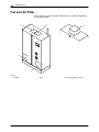
VersaBlue®
Adhesive Melters
Type VB C
with
Siemens Controller
Manual P/N 7135049A
− English −
Issued 02/07
NORDSON ENGINEERING GMBH D LÜNEBURG D GERMANY
Order number
P/N = Order number for Nordson products
Notice
This is a Nordson Corporation publication which is protected by copyright. Original copyright date 2007.
No part of this document may be photocopied, reproduced, or translated to another language without the
prior written consent of Nordson Corporation. The information contained in this publication is subject to
change without notice.
E 2007 All rights reserved.
Trademarks
AccuJet, AeroCharge, Apogee, AquaGuard, Asymtek, Automove, Autotech, Baitgun, Blue Box, CanWorks, Century, CF, Clean Coat, CleanSleeve,
CleanSpray, ColorMax, Control Coat, Coolwave, Cross-Cut, Cyclo-Kinetic, Dispensejet, DispenseMate, DuraBlue, Durafiber, Dura-Screen, Durasystem,
Easy Coat, Easymove Plus, Ecodry, Econo-Coat, e.dot, e.stylized, EFD, ETI, Excel 2000, Fillmaster, FlexiCoat, Flexi-Spray, Flex-O-Coat, Flow Sentry,
Fluidmove, FoamMelt, FoamMix, HDLV, Heli-flow, Helix, Horizon, Hot Shot, iControl, iFlow, Isocoil, Isocore, Iso-Flo, iTRAX, JR, KB30, Kinetix,
Little Squirt, LogiComm, Magnastatic, March, MEG, Meltex, Microcoat, Micromark, MicroSet, Millenium, Mini Squirt, Moist-Cure, Mountaingate,
MultiScan, Nordson, OmniScan, OptiMix, Package of Values, PatternView, PermaFlo, Plasmod, PluraFoam, Porous Coat, PowderGrid,
Powderware, Prism, Printplus, ProBlue, Prodigy, Pro-Flo, ProLink, Pro-Meter, Pro-Stream, RBX, Rhino, Saturn, Scoreguard, SC5, S. design stylized,
Seal Sentry, Select Charge, Select Coat, Select Cure, Slautterback, Smart-Coat, Solder Plus, Spectrum, Speed-Coat, Spraymelt, Spray Squirt,
Super Squirt, SureBead, Sure Clean, Sure Coat, Sure-Max, Tela-Therm, Tracking Plus, TRAK, Trends, Tribomatic, Ultra, Ultrasaver, UniScan,
UpTime, Vantage, Veritec, VersaBlue, Versa-Coat, Versa-Screen, Versa-Spray, Walcom, Watermark, When you expect more. are registered trademarks
− ® − of Nordson Corporation.
Accubar, Advanced Plasma Systems, AeroDeck, AeroWash, AltaBlue, AquaCure, ATS, Auto-Flo, AutoScan, Best Choice, BetterBook, Blue Series,
CanNeck, Celero, Chameleon, Check Mate, ClassicBlue, Color-on-Demand, Controlled Fiberization, Control Weave, cScan, CPX, DispensLink,
Dry Cure, DuraBraid, DuraCoat, DuraDrum, DuraPail, E-Nordson, Easy Clean, EasyOn, Eclipse, Equi=Bead, ESP, Exchange Plus, FilEasy, Fill Sentry,
FluxPlus, Gluie, G-Net, G-Site, Ink-Dot, iON, Iso-Flex, iTrend, KVLP, Lacquer Cure, Lean Cell, Maverick, Maxima, MicroFin, MicroMax, Mikros,
MiniBlue, MiniEdge, Minimeter, Multifil, Myritex, OptiStroke, Origin, Partnership+Plus, PatternJet, PatternPro, PCI, Pinnacle, PluraMix, Powder Pilot,
Powercure, PreciseCoat, Primarc, Process Sentry, Pulse Spray, PurTech, Quad Cure, Ready Coat, Royal Blue, Select Series, Sensomatic,
Shaftshield, SheetAire, Smart, SolidBlue, Spectral, Spectronic, SpeedKing, Spray Works, Summit, Sure Brand, SureMix, SureSeal, Sure Wrap,
Swirl Coat, Tempus, ThruWave, Trade Plus, TrueBlue, Ultrasmart, Universal, ValveMate, Viper, Vista, VersaDrum, VersaPail, WebCure, 2 Rings (Design)
are trademarks − T − of Nordson Corporation.
Designations and trademarks stated in this document may be brands that, when used by third parties for their own purposes,
could lead to violation of the owners’ rights.
P/N 7135049A
VBC_Siemens
E 2007 Nordson Corporation
Table of Contents
I
Table of Contents
E 2007 Nordson Corporation
Nordson International . . . . . . . . . . . . . . . . . . . . . . . . . . . . . . . . . . .
Europe . . . . . . . . . . . . . . . . . . . . . . . . . . . . . . . . . . . . . . . . . . . . . . . . .
Distributors in Eastern & Southern Europe . . . . . . . . . . . . . . . .
Outside Europe / Hors d’Europe / Fuera de Europa . . . . . . . . . . .
Africa / Middle East . . . . . . . . . . . . . . . . . . . . . . . . . . . . . . . . . . . .
Asia / Australia / Latin America . . . . . . . . . . . . . . . . . . . . . . . . . .
Japan . . . . . . . . . . . . . . . . . . . . . . . . . . . . . . . . . . . . . . . . . . . . . . . .
North America . . . . . . . . . . . . . . . . . . . . . . . . . . . . . . . . . . . . . . . .
O-1
O-1
O-1
O-2
O-2
O-2
O-2
O-2
Safety . . . . . . . . . . . . . . . . . . . . . . . . . . . . . . . . . . . . . . . . . . . . . . . . . .
Safety Alert Symbols . . . . . . . . . . . . . . . . . . . . . . . . . . . . . . . . . . . . .
Responsibilities of the Equipment Owner . . . . . . . . . . . . . . . . . . . .
Safety Information . . . . . . . . . . . . . . . . . . . . . . . . . . . . . . . . . . . . .
Instructions, Requirements, and Standards . . . . . . . . . . . . . . .
User Qualifications . . . . . . . . . . . . . . . . . . . . . . . . . . . . . . . . . . . .
Applicable Industry Safety Practices . . . . . . . . . . . . . . . . . . . . . . . .
Intended Use of the Equipment . . . . . . . . . . . . . . . . . . . . . . . . . .
Instructions and Safety Messages . . . . . . . . . . . . . . . . . . . . . . .
Installation Practices . . . . . . . . . . . . . . . . . . . . . . . . . . . . . . . . . . .
Operating Practices . . . . . . . . . . . . . . . . . . . . . . . . . . . . . . . . . . . .
Maintenance and Repair Practices . . . . . . . . . . . . . . . . . . . . . . .
Equipment Safety Information . . . . . . . . . . . . . . . . . . . . . . . . . . . . .
Equipment Shutdown . . . . . . . . . . . . . . . . . . . . . . . . . . . . . . . . . .
Relieving System Hydraulic Pressure . . . . . . . . . . . . . . . . . .
De-energizing the System . . . . . . . . . . . . . . . . . . . . . . . . . . . .
Disabling the Guns . . . . . . . . . . . . . . . . . . . . . . . . . . . . . . . . . .
General Safety Warnings and Cautions . . . . . . . . . . . . . . . . . . .
Other Safety Precautions . . . . . . . . . . . . . . . . . . . . . . . . . . . . . . .
First Aid . . . . . . . . . . . . . . . . . . . . . . . . . . . . . . . . . . . . . . . . . . . . . .
1-1
1-1
1-2
1-2
1-2
1-3
1-4
1-4
1-4
1-5
1-5
1-6
1-7
1-7
1-7
1-7
1-8
1-9
1-12
1-12
VBC_Siemens
P/N 7135049A
II
Table of Contents
Introduction . . . . . . . . . . . . . . . . . . . . . . . . . . . . . . . . . . . . . . . . . . . .
Intended Use . . . . . . . . . . . . . . . . . . . . . . . . . . . . . . . . . . . . . . . . . . . .
Area of Use (EMC) . . . . . . . . . . . . . . . . . . . . . . . . . . . . . . . . . . . .
Operating Restrictions . . . . . . . . . . . . . . . . . . . . . . . . . . . . . . .
Unintended Use − Examples − . . . . . . . . . . . . . . . . . . . . . . . . . .
Residual Risks . . . . . . . . . . . . . . . . . . . . . . . . . . . . . . . . . . . . . . . . . .
Definition of Terms . . . . . . . . . . . . . . . . . . . . . . . . . . . . . . . . . . . . . . .
Interface Standard I/O . . . . . . . . . . . . . . . . . . . . . . . . . . . . . . . . .
Interface Key-to-line Mode . . . . . . . . . . . . . . . . . . . . . . . . . . . . . .
Encoder . . . . . . . . . . . . . . . . . . . . . . . . . . . . . . . . . . . . . . . . . . .
Symbols . . . . . . . . . . . . . . . . . . . . . . . . . . . . . . . . . . . . . . . . . . . . . . . .
Melter Description . . . . . . . . . . . . . . . . . . . . . . . . . . . . . . . . . . . . . . . .
Tank . . . . . . . . . . . . . . . . . . . . . . . . . . . . . . . . . . . . . . . . . . . . . . . . .
Safety Valve Plate . . . . . . . . . . . . . . . . . . . . . . . . . . . . . . . . . . . . .
Tank Isolation Valve . . . . . . . . . . . . . . . . . . . . . . . . . . . . . . . . .
Safety Valve . . . . . . . . . . . . . . . . . . . . . . . . . . . . . . . . . . . . . . . .
Mechanical Pressure Control Valve . . . . . . . . . . . . . . . . . . . . . .
Pneumatic Pressure Control Valve . . . . . . . . . . . . . . . . . . . . . . .
Air Relief Valve . . . . . . . . . . . . . . . . . . . . . . . . . . . . . . . . . . . . . . . .
Material Flow . . . . . . . . . . . . . . . . . . . . . . . . . . . . . . . . . . . . . . . . .
Identification of Hose Connections . . . . . . . . . . . . . . . . . . . . . . .
Electrical Cabinet . . . . . . . . . . . . . . . . . . . . . . . . . . . . . . . . . . . . . . . .
Side with Receptacles . . . . . . . . . . . . . . . . . . . . . . . . . . . . . . . . . .
Options . . . . . . . . . . . . . . . . . . . . . . . . . . . . . . . . . . . . . . . . . . . . . . . . .
Level Control / Overflow Protection . . . . . . . . . . . . . . . . . . . . . .
Pressure Display . . . . . . . . . . . . . . . . . . . . . . . . . . . . . . . . . . . . . .
Pressure Display . . . . . . . . . . . . . . . . . . . . . . . . . . . . . . . . . . . .
Pressure Display and Pressure Control . . . . . . . . . . . . . . . .
Pressure Build-up . . . . . . . . . . . . . . . . . . . . . . . . . . . . . . . . . . .
ID Plate . . . . . . . . . . . . . . . . . . . . . . . . . . . . . . . . . . . . . . . . . . . . . . . .
P/N 7135049A
VBC_Siemens
2-1
2-1
2-1
2-1
2-2
2-2
2-3
2-3
2-3
2-3
2-3
2-4
2-6
2-6
2-6
2-6
2-6
2-7
2-7
2-7
2-8
2-9
2-9
2-10
2-10
2-11
2-11
2-11
2-11
2-12
E 2007 Nordson Corporation
Table of Contents
III
Installation . . . . . . . . . . . . . . . . . . . . . . . . . . . . . . . . . . . . . . . . . . . . .
3-1
Transport . . . . . . . . . . . . . . . . . . . . . . . . . . . . . . . . . . . . . . . . . . . . . . .
3-1
Storage . . . . . . . . . . . . . . . . . . . . . . . . . . . . . . . . . . . . . . . . . . . . . . . . .
3-1
Unpacking . . . . . . . . . . . . . . . . . . . . . . . . . . . . . . . . . . . . . . . . . . . . . .
3-1
Lifting (Unpacked Melter) . . . . . . . . . . . . . . . . . . . . . . . . . . . . . . .
3-2
Installation Requirements . . . . . . . . . . . . . . . . . . . . . . . . . . . . . . . . .
3-2
Exhausting Material Vapors . . . . . . . . . . . . . . . . . . . . . . . . . . . . .
3-2
Required Space . . . . . . . . . . . . . . . . . . . . . . . . . . . . . . . . . . . . . . .
3-3
Installation Personnel’s Experience . . . . . . . . . . . . . . . . . . . . . . . . .
3-4
Screwing on Light Tower (Option) . . . . . . . . . . . . . . . . . . . . . . . . . .
3-4
Casters . . . . . . . . . . . . . . . . . . . . . . . . . . . . . . . . . . . . . . . . . . . . . . . . .
3-4
Installing Kit . . . . . . . . . . . . . . . . . . . . . . . . . . . . . . . . . . . . . . . . . .
3-4
Electrical Connections . . . . . . . . . . . . . . . . . . . . . . . . . . . . . . . . . . . .
3-5
Important Note When Using Residual Current Circuit Breakers . . . . . . . .
3-5
Laying Cable . . . . . . . . . . . . . . . . . . . . . . . . . . . . . . . . . . . . . . . . . .
3-5
Operating Voltage . . . . . . . . . . . . . . . . . . . . . . . . . . . . . . . . . . . . .
3-5
External Control/Signal Circuits . . . . . . . . . . . . . . . . . . . . . . . . . .
3-5
Power Supply Connection . . . . . . . . . . . . . . . . . . . . . . . . . . . . . .
3-6
Connecting Hose . . . . . . . . . . . . . . . . . . . . . . . . . . . . . . . . . . . . . . . .
3-7
Connecting Electrically . . . . . . . . . . . . . . . . . . . . . . . . . . . . . . . . .
3-7
Connecting . . . . . . . . . . . . . . . . . . . . . . . . . . . . . . . . . . . . . . . . . . .
3-7
Second Open-jawed Wrench . . . . . . . . . . . . . . . . . . . . . . . . .
3-7
Disconnecting . . . . . . . . . . . . . . . . . . . . . . . . . . . . . . . . . . . . . . . . .
3-8
Relieving Pressure . . . . . . . . . . . . . . . . . . . . . . . . . . . . . . . . . .
3-8
Connecting Filling Valve (Option) . . . . . . . . . . . . . . . . . . . . . . . . . . .
3-9
Conditioning Compressed Air . . . . . . . . . . . . . . . . . . . . . . . . . . .
3-9
Interface Assignment . . . . . . . . . . . . . . . . . . . . . . . . . . . . . . . . . . . . .
3-10
Interface Standard I/O − Standard Assignment for XS 2 − . . .
3-10
General Information . . . . . . . . . . . . . . . . . . . . . . . . . . . . . . . . .
3-10
Interface Standard I/O − Standard Assignment for XS 2.1 − .
3-12
Standard I/O Interface − XS2 Assignment with
Option Solenoid Valve Control − . . . . . . . . . . . . . . . . . . . . . . . . .
3-13
Interface Standard I/O − XS2.1 Assignment with
Option Solenoid Valve Control − . . . . . . . . . . . . . . . . . . . . . . . . .
3-15
Interface Gun Solenoid Valve Control . . . . . . . . . . . . . . . . . . . .
3-16
Interface Key-to-line Mode . . . . . . . . . . . . . . . . . . . . . . . . . . . . . .
3-17
One Line Speed Signal Input for all Motors . . . . . . . . . . . . .
3-17
Separate Line Speed Signal Inputs . . . . . . . . . . . . . . . . . . . .
3-17
Interface Air run-up . . . . . . . . . . . . . . . . . . . . . . . . . . . . . . . . . . . .
3-17
Interface Level Control . . . . . . . . . . . . . . . . . . . . . . . . . . . . . . . . .
3-18
Removing Melter . . . . . . . . . . . . . . . . . . . . . . . . . . . . . . . . . . . . . . . . .
3-19
Disposing of Melter . . . . . . . . . . . . . . . . . . . . . . . . . . . . . . . . . . . . . . .
3-19
Operation . . . . . . . . . . . . . . . . . . . . . . . . . . . . . . . . . . . . . . . . . . . . . .
General Information . . . . . . . . . . . . . . . . . . . . . . . . . . . . . . . . . . . . . .
Meaning of Colors . . . . . . . . . . . . . . . . . . . . . . . . . . . . . . . . . . . . .
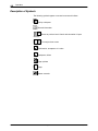
Description of Symbols . . . . . . . . . . . . . . . . . . . . . . . . . . . . . . . . .
Keys with and without Indication Lamp . . . . . . . . . . . . . . . . . . .
Input Window . . . . . . . . . . . . . . . . . . . . . . . . . . . . . . . . . . . . . . . . .
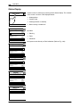
Status Display . . . . . . . . . . . . . . . . . . . . . . . . . . . . . . . . . . . . . . . .
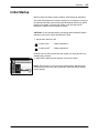
Initial Startup . . . . . . . . . . . . . . . . . . . . . . . . . . . . . . . . . . . . . . . . . . . .
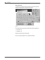
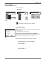
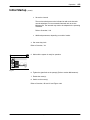
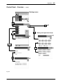
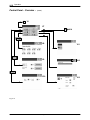
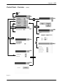
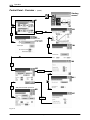
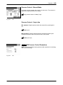
Control Panel Setup . . . . . . . . . . . . . . . . . . . . . . . . . . . . . . . . .
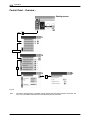
Control Panel − Overview − . . . . . . . . . . . . . . . . . . . . . . . . . . . . .
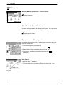
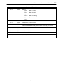
Filling the Tank . . . . . . . . . . . . . . . . . . . . . . . . . . . . . . . . . . . . . . . . . .
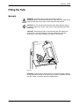
Manually . . . . . . . . . . . . . . . . . . . . . . . . . . . . . . . . . . . . . . . . . . . . .
Maximum Level . . . . . . . . . . . . . . . . . . . . . . . . . . . . . . . . . . . . .
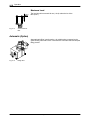
Automatic (Option) . . . . . . . . . . . . . . . . . . . . . . . . . . . . . . . . . . . . .
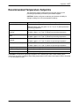
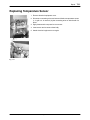
Recommended Temperature Setpoints . . . . . . . . . . . . . . . . . . . . . .
E 2007 Nordson Corporation
VBC_Siemens
4-1
4-1
4-1
4-2
4-3
4-3
4-4
4-5
4-7
4-10
4-15
4-15
4-16
4-16
4-17
P/N 7135049A
IV
Table of Contents
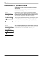
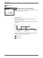
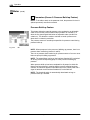
Heatup Guided by Reference Channel . . . . . . . . . . . . . . . . . . . . . .
Undertemperature Interlock . . . . . . . . . . . . . . . . . . . . . . . . . . . . . . .
Motor Startup Protection . . . . . . . . . . . . . . . . . . . . . . . . . . . . . . . . . .
Acknowledge Startup Protection . . . . . . . . . . . . . . . . . . . . . . .
Daily Startup . . . . . . . . . . . . . . . . . . . . . . . . . . . . . . . . . . . . . . . . . . . .
Daily Switchoff . . . . . . . . . . . . . . . . . . . . . . . . . . . . . . . . . . . . . . . . . . .
Switching Off in an Emergency . . . . . . . . . . . . . . . . . . . . . . . . . . . .
TP 270 Control Panel . . . . . . . . . . . . . . . . . . . . . . . . . . . . . . . . . . . . .
Melter Modes − Overview . . . . . . . . . . . . . . . . . . . . . . . . . . . . . . .
Starting Screen . . . . . . . . . . . . . . . . . . . . . . . . . . . . . . . . . . . . . . .
Temperature Parameters . . . . . . . . . . . . . . . . . . . . . . . . . . . . . . .
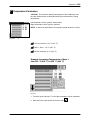
Example: Increasing Temperature of Hose 1 from
220 °C (428 °F) to 230 °C (446 °F) . . . . . . . . . . . . . . . . . . .
Parameters (Screen 1: Alarm Values) . . . . . . . . . . . . . . . . . .
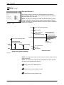
Graphic Presentation of Temperature Parameters . . . . . . .
Parameters (Screen 2: Activate Channel, Mode,
Control Parameters) . . . . . . . . . . . . . . . . . . . . . . . . . . . . . . . . .
Parameters (Screen 3) . . . . . . . . . . . . . . . . . . . . . . . . . . . . . . .
Assigning Temperature Channel to a Group . . . . . . . . . . . . .
Melter . . . . . . . . . . . . . . . . . . . . . . . . . . . . . . . . . . . . . . . . . . . . . . . .
Entering/Exiting Standby . . . . . . . . . . . . . . . . . . . . . . . . . . . . .
Switching On/Off All Motors (Collective Enable) . . . . . . . . .
Switching On/Off Heaters . . . . . . . . . . . . . . . . . . . . . . . . . . . .
Switching On/Off Seven-day Clock . . . . . . . . . . . . . . . . . . . .
Alarm Log . . . . . . . . . . . . . . . . . . . . . . . . . . . . . . . . . . . . . . . . . .
Information (Melter and Control System) . . . . . . . . . . . . . . .
Working with Application Groups . . . . . . . . . . . . . . . . . . . . . .
Setup (Screen 1: Seven-day Clock, Standby, Level) . . . . .
Setup (Screen 2: e.g. Units, Ready Delay Time,
Service Interval, Field Bus) . . . . . . . . . . . . . . . . . . . . . . . . . . .
Setup (Screen 3: e.g. Nordson Setup,
Pressure Sensor Setup) . . . . . . . . . . . . . . . . . . . . . . . . . . . . . .
Master Overwrite (Pressure) . . . . . . . . . . . . . . . . . . . . . . . . . .
Motor . . . . . . . . . . . . . . . . . . . . . . . . . . . . . . . . . . . . . . . . . . . . . . . .
Switching On/Off Motor (Individual Enable) . . . . . . . . . . . . .
Selecting Key-to-line or Manual Mode . . . . . . . . . . . . . . . . . .
Parameters (Screen 1: Type of Motor Enable,
Adaptation to Parent Machine) . . . . . . . . . . . . . . . . . . . . . . . .
Parameters (Screen 2: Key-to-line) . . . . . . . . . . . . . . . . . . . .
Parameters (Screen 3: Threshold Switch) . . . . . . . . . . . . . .
Parameters (Screen 4: Pressure Alarms,
Switching Between Speed / Pressure Control,
Pressure Setpoints) . . . . . . . . . . . . . . . . . . . . . . . . . . . . . . . . .
Pressure Sensor A . . . . . . . . . . . . . . . . . . . . . . . . . . . . . . . . . .
Pressure Sensor C . . . . . . . . . . . . . . . . . . . . . . . . . . . . . . . . . .
Speed Control − Manual Mode . . . . . . . . . . . . . . . . . . . . . . . .
Example: Increase Pump Speed . . . . . . . . . . . . . . . . . . . . . .
Pressure Control − Manual Mode . . . . . . . . . . . . . . . . . . . . . .
Pressure Control − Key-to-line . . . . . . . . . . . . . . . . . . . . . . . .
PID Pressure Control Parameters . . . . . . . . . . . . . . . . . . . . .
Parameters (Screen 5: Pressure Build-up Feature) . . . . . .
Pressure Build-up Feature . . . . . . . . . . . . . . . . . . . . . . . . . . . .
Motor Circuit Switch (Motor Maintenance Switch) . . . . . . . . . .
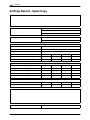
Settings Record . . . . . . . . . . . . . . . . . . . . . . . . . . . . . . . . . . . . . . . . .
Settings Record - Spare Copy . . . . . . . . . . . . . . . . . . . . . . . . . . . . .
P/N 7135049A
VBC_Siemens
4-18
4-19
4-19
4-19
4-20
4-20
4-20
4-21
4-21
4-22
4-23
4-23
4-24
4-26
4-27
4-28
4-28
4-30
4-30
4-30
4-31
4-31
4-31
4-32
4-33
4-34
4-37
4-39
4-39
4-40
4-40
4-41
4-42
4-43
4-44
4-45
4-46
4-47
4-48
4-48
4-49
4-49
4-49
4-50
4-50
4-52
4-53
4-54
E 2007 Nordson Corporation
Table of Contents
Maintenance . . . . . . . . . . . . . . . . . . . . . . . . . . . . . . . . . . . . . . . . . . .
Risk of Burns . . . . . . . . . . . . . . . . . . . . . . . . . . . . . . . . . . . . . . . . . . . .
Relieving Pressure . . . . . . . . . . . . . . . . . . . . . . . . . . . . . . . . . . . . . . .
Important when Using Cleaning Agents . . . . . . . . . . . . . . . . . . . . .
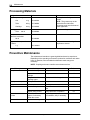
Processing Materials . . . . . . . . . . . . . . . . . . . . . . . . . . . . . . . . . . . . .
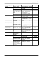
Preventive Maintenance . . . . . . . . . . . . . . . . . . . . . . . . . . . . . . . . . .
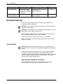
External Cleaning . . . . . . . . . . . . . . . . . . . . . . . . . . . . . . . . . . . . . . . .
Control Panel . . . . . . . . . . . . . . . . . . . . . . . . . . . . . . . . . . . . . . . . .
Removing Paint Splatters and Grease . . . . . . . . . . . . . . . . .
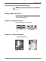
Visual Inspection for External Damage . . . . . . . . . . . . . . . . . . . . . .
Safety and Function Tests . . . . . . . . . . . . . . . . . . . . . . . . . . . . . . . . .
Detaching Protective Panels . . . . . . . . . . . . . . . . . . . . . . . . . . . . . . .
Detaching Insulation Blanket . . . . . . . . . . . . . . . . . . . . . . . . . . . . . .
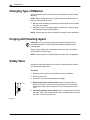
Changing Type of Material . . . . . . . . . . . . . . . . . . . . . . . . . . . . . . . .
Purging with Cleaning Agent . . . . . . . . . . . . . . . . . . . . . . . . . . . . . . .
Safety Valve . . . . . . . . . . . . . . . . . . . . . . . . . . . . . . . . . . . . . . . . . . . .
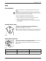
Tank . . . . . . . . . . . . . . . . . . . . . . . . . . . . . . . . . . . . . . . . . . . . . . . . . . .
Draining Material . . . . . . . . . . . . . . . . . . . . . . . . . . . . . . . . . . . . . .
Cleaning Tank by Hand . . . . . . . . . . . . . . . . . . . . . . . . . . . . . . . . .
Tightening Fixing Screws . . . . . . . . . . . . . . . . . . . . . . . . . . . . . . .
Fan and Air Filter . . . . . . . . . . . . . . . . . . . . . . . . . . . . . . . . . . . . . . . .
Gear Pump . . . . . . . . . . . . . . . . . . . . . . . . . . . . . . . . . . . . . . . . . . . . .
Checking for Leakage . . . . . . . . . . . . . . . . . . . . . . . . . . . . . . . . . .
Gear Pumps with Variseal . . . . . . . . . . . . . . . . . . . . . . . . . . . .
Replacing Variseal . . . . . . . . . . . . . . . . . . . . . . . . . . . . . . . . . .
Gear Pumps with Gland Bolt . . . . . . . . . . . . . . . . . . . . . . . . . .
Tightening Gland Bolt . . . . . . . . . . . . . . . . . . . . . . . . . . . . . . . .
Tightening Fixing Screws . . . . . . . . . . . . . . . . . . . . . . . . . . . . . . .
Motor / Gear Box . . . . . . . . . . . . . . . . . . . . . . . . . . . . . . . . . . . . . . . .
Changing Lubricant . . . . . . . . . . . . . . . . . . . . . . . . . . . . . . . . . . . .
Lubricant Selection . . . . . . . . . . . . . . . . . . . . . . . . . . . . . . . . . . . .
Pressure Control Valve . . . . . . . . . . . . . . . . . . . . . . . . . . . . . . . . . . .
Important for Mechanical Pressure Control Valve . . . . . . . . . .
Measuring Insertion Depth . . . . . . . . . . . . . . . . . . . . . . . . . . . .
Adjusting Setting Screw . . . . . . . . . . . . . . . . . . . . . . . . . . . . . .
Installing Service Kit . . . . . . . . . . . . . . . . . . . . . . . . . . . . . . . . . . .
Filter Cartridge . . . . . . . . . . . . . . . . . . . . . . . . . . . . . . . . . . . . . . . . . .
Replacing Filter Cartridge . . . . . . . . . . . . . . . . . . . . . . . . . . . . . . .
Removing Filter Cartridge . . . . . . . . . . . . . . . . . . . . . . . . . . . .
Cleaning Filter Cartridge . . . . . . . . . . . . . . . . . . . . . . . . . . . . .
Assembling Filter Cartridge . . . . . . . . . . . . . . . . . . . . . . . . . . .
Installing Filter Cartridge . . . . . . . . . . . . . . . . . . . . . . . . . . . . .
Installing Service Kit . . . . . . . . . . . . . . . . . . . . . . . . . . . . . . . . . . .
Safety Valve Plate . . . . . . . . . . . . . . . . . . . . . . . . . . . . . . . . . . . . . . .
Installing Service Kit . . . . . . . . . . . . . . . . . . . . . . . . . . . . . . . . . . .
Tank Isolation Valve . . . . . . . . . . . . . . . . . . . . . . . . . . . . . . . . . . . . . .
Installing Service Kit . . . . . . . . . . . . . . . . . . . . . . . . . . . . . . . . . . .
Pneumatic Safety Valve . . . . . . . . . . . . . . . . . . . . . . . . . . . . . . . . . . .
Performance Check . . . . . . . . . . . . . . . . . . . . . . . . . . . . . . . . . . . .
Cleaning . . . . . . . . . . . . . . . . . . . . . . . . . . . . . . . . . . . . . . . . . . . . .
Pressure Sensor . . . . . . . . . . . . . . . . . . . . . . . . . . . . . . . . . . . . . . . . .
Cleaning Separating Membrane . . . . . . . . . . . . . . . . . . . . . . . . .
Screwing in Pressure Sensor . . . . . . . . . . . . . . . . . . . . . . . . . . . .
Filling Valve . . . . . . . . . . . . . . . . . . . . . . . . . . . . . . . . . . . . . . . . . . . . .
Replacing Control Module . . . . . . . . . . . . . . . . . . . . . . . . . . . . . .
Maintenance Record Form . . . . . . . . . . . . . . . . . . . . . . . . . . . . . . . .
E 2007 Nordson Corporation
VBC_Siemens
V
5-1
5-1
5-1
5-1
5-2
5-2
5-4
5-4
5-4
5-5
5-5
5-5
5-5
5-6
5-6
5-6
5-7
5-7
5-7
5-7
5-8
5-9
5-9
5-9
5-9
5-10
5-10
5-10
5-11
5-11
5-12
5-12
5-12
5-12
5-12
5-13
5-14
5-14
5-14
5-15
5-15
5-16
5-16
5-17
5-17
5-18
5-18
5-19
5-19
5-19
5-20
5-20
5-20
5-21
5-21
5-22
P/N 7135049A
VI
Table of Contents
P/N 7135049A
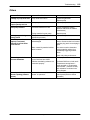
Troubleshooting . . . . . . . . . . . . . . . . . . . . . . . . . . . . . . . . . . . . . . . .
Helpful Tips . . . . . . . . . . . . . . . . . . . . . . . . . . . . . . . . . . . . . . . . . . . . .
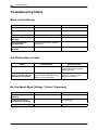
Troubleshooting Tables . . . . . . . . . . . . . . . . . . . . . . . . . . . . . . . . . . .
Melter not Functioning . . . . . . . . . . . . . . . . . . . . . . . . . . . . . . . . .
One Channel does not Heat . . . . . . . . . . . . . . . . . . . . . . . . . . . . .
No Line Speed Signal (Voltage / Current / Frequency) . . . . . .
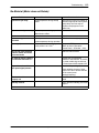
No Material (Motor does not Rotate) . . . . . . . . . . . . . . . . . . . . .
No Material (Motor Rotating) . . . . . . . . . . . . . . . . . . . . . . . . . . . .
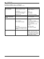
Too Little Material or Irregular Feeding . . . . . . . . . . . . . . . . . . . .
Material Pressure too High . . . . . . . . . . . . . . . . . . . . . . . . . . . . . .
Material Pressure too Low . . . . . . . . . . . . . . . . . . . . . . . . . . . . . .
Incorrect Motor Rotation in Key-to-line Mode . . . . . . . . . . . . . .
Material Residue in Tank . . . . . . . . . . . . . . . . . . . . . . . . . . . . . . .
Material Hardens in Tank . . . . . . . . . . . . . . . . . . . . . . . . . . . . . . .
Filling Valve (Option) . . . . . . . . . . . . . . . . . . . . . . . . . . . . . . . . . . .
Others . . . . . . . . . . . . . . . . . . . . . . . . . . . . . . . . . . . . . . . . . . . . . . .
6-1
6-1
6-2
6-2
6-2
6-2
6-3
6-5
6-5
6-6
6-6
6-6
6-7
6-7
6-8
6-9
Repair . . . . . . . . . . . . . . . . . . . . . . . . . . . . . . . . . . . . . . . . . . . . . . . . .
Risk of Burns . . . . . . . . . . . . . . . . . . . . . . . . . . . . . . . . . . . . . . . . . . . .
Observe Before Performing Repairs . . . . . . . . . . . . . . . . . . . . . . . .
Relieving Pressure . . . . . . . . . . . . . . . . . . . . . . . . . . . . . . . . . . . . . . .
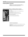
Replacing Motor Controller . . . . . . . . . . . . . . . . . . . . . . . . . . . . . . . .
Replacing Profibus Module or I/O Module of Motor Controller
Profibus Terminating Resistor . . . . . . . . . . . . . . . . . . . . . . . . .
Replacing Pressure Sensor . . . . . . . . . . . . . . . . . . . . . . . . . . . . . . .
Profibus Terminating Resistor . . . . . . . . . . . . . . . . . . . . . . . . . . .
Procedure . . . . . . . . . . . . . . . . . . . . . . . . . . . . . . . . . . . . . . . . . . . .
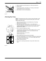
Replacing Gear Pump . . . . . . . . . . . . . . . . . . . . . . . . . . . . . . . . . . . .
Tank Isolation Valve . . . . . . . . . . . . . . . . . . . . . . . . . . . . . . . . . . . .
Detaching Gear Pump . . . . . . . . . . . . . . . . . . . . . . . . . . . . . . . . .
Attaching Gear Pump . . . . . . . . . . . . . . . . . . . . . . . . . . . . . . . . . .
Important Regarding Coupling . . . . . . . . . . . . . . . . . . . . . . . .
Replacing Motor . . . . . . . . . . . . . . . . . . . . . . . . . . . . . . . . . . . . . . . . .
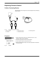
Replacing Safety Valve . . . . . . . . . . . . . . . . . . . . . . . . . . . . . . . . . . .
Safety Valve . . . . . . . . . . . . . . . . . . . . . . . . . . . . . . . . . . . . . . . . . .
Safety Valve with Reed Switch . . . . . . . . . . . . . . . . . . . . . . . . . .
Replacing Filter Cartridge . . . . . . . . . . . . . . . . . . . . . . . . . . . . . . . . .
Observe when Performing Work behind
Electrical Equipment Cover . . . . . . . . . . . . . . . . . . . . . . . . . . . . . . . .
Replacing Thermostat . . . . . . . . . . . . . . . . . . . . . . . . . . . . . . . . . . . .
Replacing Heating Connection Insulation . . . . . . . . . . . . . . . . . . . .
Replacing Temperature Sensor . . . . . . . . . . . . . . . . . . . . . . . . . . . .
Replacing Level Evaluator (Option) . . . . . . . . . . . . . . . . . . . . . . . . .
Important Notes . . . . . . . . . . . . . . . . . . . . . . . . . . . . . . . . . . . . . . .
Calibrating . . . . . . . . . . . . . . . . . . . . . . . . . . . . . . . . . . . . . . . . . . . .
Prerequisites . . . . . . . . . . . . . . . . . . . . . . . . . . . . . . . . . . . . . . .
Replacing Overflow Protection Evaluator (Option) . . . . . . . . . . . .
Important Notes . . . . . . . . . . . . . . . . . . . . . . . . . . . . . . . . . . . . . . .
Calibrating . . . . . . . . . . . . . . . . . . . . . . . . . . . . . . . . . . . . . . . . . . . .
Prerequisites . . . . . . . . . . . . . . . . . . . . . . . . . . . . . . . . . . . . . . .
Sensor Break . . . . . . . . . . . . . . . . . . . . . . . . . . . . . . . . . . . . . . .
Limit Switching Points . . . . . . . . . . . . . . . . . . . . . . . . . . . . . . .
7-1
7-1
7-1
7-1
7-2
7-2
7-2
7-3
7-3
7-3
7-4
7-4
7-4
7-5
7-6
7-7
7-8
7-8
7-8
7-9
VBC_Siemens
7-9
7-9
7-10
7-11
7-12
7-12
7-13
7-13
7-14
7-14
7-15
7-15
7-15
7-15
E 2007 Nordson Corporation
Table of Contents
E 2007 Nordson Corporation
VII
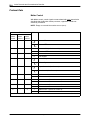
Parts . . . . . . . . . . . . . . . . . . . . . . . . . . . . . . . . . . . . . . . . . . . . . . . . . . .
How to Use Illustrated Parts List . . . . . . . . . . . . . . . . . . . . . . . . . . .
Fasteners . . . . . . . . . . . . . . . . . . . . . . . . . . . . . . . . . . . . . . . . . . . .
Component Designation . . . . . . . . . . . . . . . . . . . . . . . . . . . . . . . .
8-1
8-1
8-1
8-1
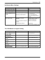
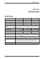
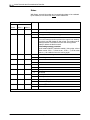
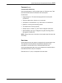
Technical Data . . . . . . . . . . . . . . . . . . . . . . . . . . . . . . . . . . . . . . . . . .
General Data . . . . . . . . . . . . . . . . . . . . . . . . . . . . . . . . . . . . . . . . . . . .
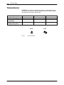
Temperatures . . . . . . . . . . . . . . . . . . . . . . . . . . . . . . . . . . . . . . . . . . .
Electrical Data . . . . . . . . . . . . . . . . . . . . . . . . . . . . . . . . . . . . . . . . . . .
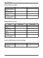
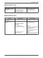
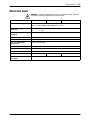
Mechanical Data . . . . . . . . . . . . . . . . . . . . . . . . . . . . . . . . . . . . . . . . .
Dimensions . . . . . . . . . . . . . . . . . . . . . . . . . . . . . . . . . . . . . . . . . . .
9-1
9-1
9-2
9-3
9-4
9-4
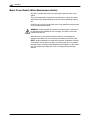
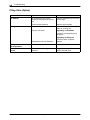
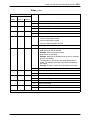
General Instructions Regarding Working with
Application Materials . . . . . . . . . . . . . . . . . . . . . . . . . . . . . . . . . . .
Definition of Terms . . . . . . . . . . . . . . . . . . . . . . . . . . . . . . . . . . . . . . .
Manufacturer Information . . . . . . . . . . . . . . . . . . . . . . . . . . . . . . . . .
Liability . . . . . . . . . . . . . . . . . . . . . . . . . . . . . . . . . . . . . . . . . . . . . . . . .
Risk of Burns . . . . . . . . . . . . . . . . . . . . . . . . . . . . . . . . . . . . . . . . . . . .
Vapors and Gases . . . . . . . . . . . . . . . . . . . . . . . . . . . . . . . . . . . . . . .
Substrate . . . . . . . . . . . . . . . . . . . . . . . . . . . . . . . . . . . . . . . . . . . . . . .
Processing Temperature . . . . . . . . . . . . . . . . . . . . . . . . . . . . . . . . . .
A-1
A-1
A-1
A-1
A-1
A-2
A-2
A-2
Index Protocols and Communication Data List . . . . . . . . . . . .
General Information . . . . . . . . . . . . . . . . . . . . . . . . . . . . . . . . . . . . . .
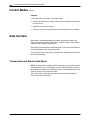
Control Modes . . . . . . . . . . . . . . . . . . . . . . . . . . . . . . . . . . . . . . . . . . .
Data Interface . . . . . . . . . . . . . . . . . . . . . . . . . . . . . . . . . . . . . . . . . . .
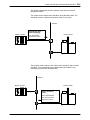
Transmission and Receive Data Block . . . . . . . . . . . . . . . . . . . .
Data Block Processing . . . . . . . . . . . . . . . . . . . . . . . . . . . . . . . . .
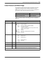
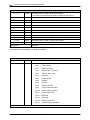
Index Protocol and Data Image . . . . . . . . . . . . . . . . . . . . . . . . . . . .
Protocol Data . . . . . . . . . . . . . . . . . . . . . . . . . . . . . . . . . . . . . . . . .
Melter Control . . . . . . . . . . . . . . . . . . . . . . . . . . . . . . . . . . . . . .
Status . . . . . . . . . . . . . . . . . . . . . . . . . . . . . . . . . . . . . . . . . . . . .
Command . . . . . . . . . . . . . . . . . . . . . . . . . . . . . . . . . . . . . . . . . .
Data Index . . . . . . . . . . . . . . . . . . . . . . . . . . . . . . . . . . . . . . . . .
Channel Number . . . . . . . . . . . . . . . . . . . . . . . . . . . . . . . . . . . .
Write Data Value . . . . . . . . . . . . . . . . . . . . . . . . . . . . . . . . . . . .
Read Data Value . . . . . . . . . . . . . . . . . . . . . . . . . . . . . . . . . . . .
Line Speed Value for Motor 1-n (Key-to-line Mode) . . . . . .
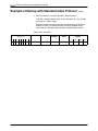
Example of Startup with Standard Index Protocol . . . . . . . . . . . . .
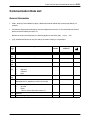
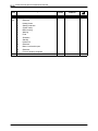
Communication Data List . . . . . . . . . . . . . . . . . . . . . . . . . . . . . . . . .
General Information . . . . . . . . . . . . . . . . . . . . . . . . . . . . . . . . . . . .
B-1
B-1
B-1
B-2
B-2
B-4
B-5
B-8
B-8
B-10
B-12
B-13
B-14
B-14
B-15
B-18
B-19
B-21
B-21
VBC_Siemens
P/N 7135049A
VIII
Table of Contents
P/N 7135049A
VBC_Siemens
E 2007 Nordson Corporation
Introduction
O-1
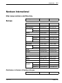
Nordson International
http://www.nordson.com/Directory
Country
Phone
Fax
Austria
43-1-707 5521
43-1-707 5517
Belgium
31-13-511 8700
31-13-511 3995
Czech Republic
4205-4159 2411
4205-4124 4971
Denmark
Hot Melt
45-43-66 0123
45-43-64 1101
Finishing
45-43-66 1133
45-43-66 1123
Finland
358-9-530 8080
358-9-530 80850
France
33-1-6412 1400
33-1-6412 1401
Erkrath
49-211-92050
49-211-254 658
Lüneburg
49-4131-8940
49-4131-894 149
Nordson UV
49-211-9205528
49-211-9252148
Italy
39-02-904 691
39-02-9078 2485
Netherlands
31-13-511 8700
31-13-511 3995
Hot Melt
47-23 03 6160
47-23 68 3636
Finishing
47-22-65 6100
47-22-65 8858
Poland
48-22-836 4495
48-22-836 7042
Portugal
351-22-961 9400
351-22-961 9409
Russia
7-812-11 86 263
7-812-11 86 263
Slovak Republic
4205-4159 2411
4205-4124 4971
Spain
34-96-313 2090
34-96-313 2244
Sweden
46-40−680 1700
46-40-932 882
Switzerland
41-61-411 3838
41-61-411 3818
Hot Melt
44-1844-26 4500
44-1844-21 5358
Finishing
44-161-495 4200
44-161-428 6716
Nordson UV
44-1753-558 000
44-1753-558 100
49-211-92050
49-211-254 658
Europe
Germany
Norway
United
Kingdom
Distributors in Eastern & Southern Europe
DED, Germany
E 2005 Nordson Corporation
All rights reserved
NI_EN_L−1105
O-2
Introduction
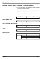
Outside Europe / Hors d’Europe / Fuera de Europa
S For your nearest Nordson office outside Europe, contact the Nordson
offices below for detailed information.
S Pour toutes informations sur représentations de Nordson dans votre
pays, veuillez contacter l’un de bureaux ci-dessous.
S Para obtener la dirección de la oficina correspondiente, por favor
diríjase a unas de las oficinas principales que siguen abajo.
Contact Nordson
Phone
Fax
DED, Germany
49-211-92050
49-211-254 658
Pacific South Division,
USA
1-440-685-4797
−
Japan
81-3-5762 2700
81-3-5762 2701
Canada
1-905-475 6730
1-905-475 8821
Hot Melt
1-770-497 3400
1-770-497 3500
Finishing
1-880-433 9319
1-888-229 4580
Nordson UV
1-440-985 4592
1-440-985 4593
Africa / Middle East
Asia / Australia / Latin America
Japan
North America
USA
NI_EN_L-1105
E 2005 Nordson Corporation
All rights reserved
Safety
1-1
Section 1
Safety
Read this section before using the equipment. This section contains
recommendations and practices applicable to the safe installation,
operation, and maintenance (hereafter referred to as “use”) of the product
described in this document (hereafter referred to as “equipment”).
Additional safety information, in the form of task-specific safety alert
messages, appears as appropriate throughout this document.
WARNING: Failure to follow the safety messages, recommendations, and
hazard avoidance procedures provided in this document can result in
personal injury, including death, or damage to equipment or property.
Safety Alert Symbols
The following safety alert symbol and signal words are used throughout this
document to alert the reader to personal safety hazards or to identify
conditions that may result in damage to equipment or property. Comply with
all safety information that follows the signal word.
WARNING: Indicates a potentially hazardous situation that, if not avoided,
can result in serious personal injury, including death.
CAUTION: Indicates a potentially hazardous situation that, if not avoided,
can result in minor or moderate personal injury.
CAUTION: (Used without the safety alert symbol) Indicates a potentially
hazardous situation that, if not avoided, can result in damage to equipment
or property.
E 2004 Nordson Corporation
A1EN−01−[XX−SAFE]−10
1-2
Safety
Responsibilities of the Equipment Owner
Equipment owners are responsible for managing safety information,
ensuring that all instructions and regulatory requirements for use of the
equipment are met, and for qualifying all potential users.
Safety Information
S Research and evaluate safety information from all applicable sources,
including the owner-specific safety policy, best industry practices,
governing regulations, material manufacturer’s product information, and
this document.
S Make safety information available to equipment users in accordance
with governing regulations. Contact the authority having jurisdiction for
information.
S Maintain safety information, including the safety labels affixed to the
equipment, in readable condition.
Instructions, Requirements, and Standards
S Ensure that the equipment is used in accordance with the information
provided in this document, governing codes and regulations, and best
industry practices.
S If applicable, receive approval from your facility’s engineering or safety
department, or other similar function within your organization, before
installing or operating the equipment for the first time.
S Provide appropriate emergency and first aid equipment.
S Conduct safety inspections to ensure required practices are being
followed.
S Re-evaluate safety practices and procedures whenever changes are
made to the process or equipment.
A1EN−01−[XX−SAFE]−10
E 2004 Nordson Corporation
Safety
1-3
User Qualifications
Equipment owners are responsible for ensuring that users:
S Receive safety training appropriate to their job function as directed
by governing regulations and best industry practices
S Are familiar with the equipment owner’s safety and accident
prevention policies and procedures
S Receive, equipment- and task-specific training from another qualified
individual
NOTE: Nordson can provide equipment-specific installation,
operation, and maintenance training. Contact your Nordson
representative for information
S Possess industry- and trade-specific skills and a level of experience
appropriate to their job function
S Are physically capable of performing their job function and are not
under the influence of any substance that degrades their mental
capacity or physical capabilities
E 2004 Nordson Corporation
A1EN−01−[XX−SAFE]−10
1-4
Safety
Applicable Industry Safety Practices
The following safety practices apply to the use of the equipment in the
manner described in this document. The information provided here is not
meant to include all possible safety practices, but represents the best safety
practices for equipment of similar hazard potential used in similar industries.
Intended Use of the Equipment
S Use the equipment only for the purposes described and within the limits
specified in this document.
S Do not modify the equipment.
S Do not use incompatible materials or unapproved auxiliary devices.
Contact your Nordson representative if you have any questions on
material compatibility or the use of non-standard auxiliary devices.
Instructions and Safety Messages
S Read and follow the instructions provided in this document and other
referenced documents.
S Familiarize yourself with the location and meaning of the safety warning
labels and tags affixed to the equipment. Refer to Safety Labels and
Tags (if available) at the end of this section.
S If you are unsure of how to use the equipment, contact your Nordson
representative for assistance.
A1EN−01−[XX−SAFE]−10
E 2004 Nordson Corporation
Safety
1-5
Installation Practices
S Install the equipment in accordance with the instructions provided in this
document and in the documentation provided with auxiliary devices.
S Ensure that the equipment is rated for the environment in which it will be
used and that the processing characteristics of the material will not
create a hazardous environment. Refer to the Material Safety Data
Sheet (MSDS) for the material.
S If the required installation configuration does not match the installation
instructions, contact your Nordson representative for assistance.
S Position the equipment for safe operation. Observe the requirements for
clearance between the equipment and other objects.
S Install lockable power disconnects to isolate the equipment and all
independently powered auxiliary devices from their power sources.
S Properly ground all equipment. Contact your local building code
enforcement agency for specific requirements.
S Ensure that fuses of the correct type and rating are installed in fused
equipment.
S Contact the authority having jurisdiction to determine the requirement for
installation permits or inspections.
Operating Practices
S Familiarize yourself with the location and operation of all safety devices
and indicators.
S Confirm that the equipment, including all safety devices (guards,
interlocks, etc.), is in good working order and that the required
environmental conditions exist.
S Use the personal protective equipment (PPE) specified for each task.
Refer to Equipment Safety Information or the material manufacturer’s
instructions and MSDS for PPE requirements.
S Do not use equipment that is malfunctioning or shows signs of a
potential malfunction.
E 2004 Nordson Corporation
A1EN−01−[XX−SAFE]−10
1-6
Safety
Maintenance and Repair Practices
S Perform scheduled maintenance activities at the intervals described in
this document.
S Relieve system hydraulic and pneumatic pressure before servicing the
equipment.
S De-energize the equipment and all auxiliary devices before servicing the
equipment.
S Use only new or factory-authorized refurbished replacement parts.
S Read and comply with the manufacturer’s instructions and the MSDS
supplied with equipment cleaning compounds.
NOTE: MSDSs for cleaning compounds that are sold by Nordson are
available at www.nordson.com or by calling your Nordson
representative.
S Confirm the correct operation of all safety devices before placing the
equipment back into operation.
S Dispose of waste cleaning compounds and residual process materials
according to governing regulations. Refer to the applicable MSDS or
contact the authority having jurisdiction for information.
S Keep equipment safety warning labels clean. Replace worn or
damaged labels.
A1EN−01−[XX−SAFE]−10
E 2004 Nordson Corporation
Safety
1-7
Equipment Safety Information
This equipment safety information is applicable to the following types of
Nordson equipment:
S hot melt and cold adhesive application equipment and all related
accessories
S pattern controllers, timers, detection and verification systems, and all
other optional process control devices
Equipment Shutdown
To safely complete many of the procedures described in this document, the
equipment must first be shut down. The level of shut down required varies
by the type of equipment in use and the procedure being completed. If
required, shut down instructions are specified at the start of the procedure.
The levels of shut down are:
Relieving System Hydraulic Pressure
Completely relieve system hydraulic pressure before breaking any hydraulic
connection or seal. Refer to the melter-specific product manual for
instructions on relieving system hydraulic pressure.
De-energizing the System
Isolate the system (melter, hoses, guns, and optional devices) from all
power sources before accessing any unprotected high-voltage wiring or
connection point.
1. Turn off the equipment and all auxiliary devices connected to the
equipment (system).
2. To prevent the equipment from being accidentally energized, lock and
tag the disconnect switch(es) or circuit breaker(s) that provide input
electrical power to the equipment and optional devices.
NOTE: Government regulations and industry standards dictate specific
requirements for the isolation of hazardous energy sources. Refer to
the appropriate regulation or standard.
E 2004 Nordson Corporation
A1EN−01−[XX−SAFE]−10
1-8
Safety
Disabling the Guns
All electrical or mechanical devices that provide an activation signal to the
guns, gun solenoid valve(s), or the melter pump must be disabled before
work can be performed on or around a gun that is connected to a
pressurized system.
1. Turn off or disconnect the gun triggering device (pattern controller, timer,
PLC, etc.).
2. Disconnect the input signal wiring to the gun solenoid valve(s).
3. Reduce the air pressure to the gun solenoid valve(s) to zero; then
relieve the residual air pressure between the regulator and the gun.
A1EN−01−[XX−SAFE]−10
E 2004 Nordson Corporation
Safety
1-9
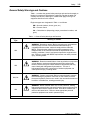
General Safety Warnings and Cautions
Table 1-1 contains the general safety warnings and cautions that apply to
Nordson hot melt and cold adhesive equipment. Review the table and
carefully read all of the warnings or cautions that apply to the type of
equipment described in this manual.
Equipment types are designated in Table 1-1 as follows:
HM = Hot melt (melters, hoses, guns, etc.)
PC = Process control
CA = Cold adhesive (dispensing pumps, pressurized container, and
guns)
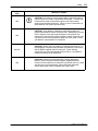
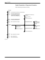
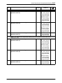
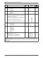
Table 1-1 General Safety Warnings and Cautions
Equipment
Type
Warning or Caution
HM
WARNING: Hazardous vapors! Before processing any polyurethane
reactive (PUR) hot melt or solvent-based material through a
compatible Nordson melter, read and comply with the material’s
MSDS. Ensure that the material’s processing temperature and
flashpoints will not be exceeded and that all requirements for safe
handling, ventilation, first aid, and personal protective equipment are
met. Failure to comply with MSDS requirements can cause personal
injury, including death.
HM
WARNING: Reactive material! Never clean any aluminum component
or flush Nordson equipment with halogenated hydrocarbon fluids.
Nordson melters and guns contain aluminum components that may
react violently with halogenated hydrocarbons. The use of
halogenated hydrocarbon compounds in Nordson equipment can
cause personal injury, including death.
HM, CA
WARNING: System pressurized! Relieve system hydraulic pressure
before breaking any hydraulic connection or seal. Failure to relieve
the system hydraulic pressure can result in the uncontrolled release of
hot melt or cold adhesive, causing personal injury.
HM
WARNING: Molten material! Wear eye or face protection, clothing
that protects exposed skin, and heat-protective gloves when servicing
equipment that contains molten hot melt. Even when solidified, hot
melt can still cause burns. Failure to wear appropriate personal
protective equipment can result in personal injury.
Continued...
E 2004 Nordson Corporation
A1EN−01−[XX−SAFE]−10
1-10 Safety
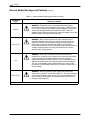
General Safety Warnings and Cautions
(contd)
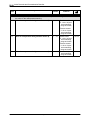
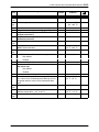
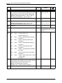
Table 1-1 General Safety Warnings and Cautions (contd)
Equipment
Type
Warning or Caution
HM, PC
WARNING: Equipment starts automatically! Remote triggering
devices are used to control automatic hot melt guns. Before working
on or near an operating gun, disable the gun’s triggering device and
remove the air supply to the gun’s solenoid valve(s). Failure to
disable the gun’s triggering device and remove the supply of air to the
solenoid valve(s) can result in personal injury.
HM, CA, PC
WARNING: Risk of electrocution! Even when switched off and
electrically isolated at the disconnect switch or circuit breaker, the
equipment may still be connected to energized auxiliary devices.
De-energize and electrically isolate all auxiliary devices before
servicing the equipment. Failure to properly isolate electrical power to
auxiliary equipment before servicing the equipment can result in
personal injury, including death.
CA
HM, CA, PC
WARNING: Risk of fire or explosion! Nordson cold adhesive
equipment is not rated for use in explosive environments and should
not be used with solvent-based adhesives that can create an
explosive atmosphere when processed. Refer to the MSDS for the
adhesive to determine its processing characteristics and limitations.
The use of incompatible solvent-based adhesives or the improper
processing of solvent-based adhesives can result in personal injury,
including death.
WARNING: Allow only personnel with appropriate training and
experience to operate or service the equipment. The use of untrained
or inexperienced personnel to operate or service the equipment can
result in injury, including death, to themselves and others and can
damage to the equipment.
Continued...
A1EN−01−[XX−SAFE]−10
E 2004 Nordson Corporation
Safety
1-11
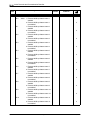
Equipment
Type
Warning or Caution
HM
CAUTION: Hot surfaces! Avoid contact with the hot metal surfaces
of guns, hoses, and certain components of the melter. If contact can
not be avoided, wear heat-protective gloves and clothing when
working around heated equipment. Failure to avoid contact with hot
metal surfaces can result in personal injury.
HM
CAUTION: Some Nordson melters are specifically designed to
process polyurethane reactive (PUR) hot melt. Attempting to process
PUR in equipment not specifically designed for this purpose can
damage the equipment and cause premature reaction of the hot melt.
If you are unsure of the equipment’s ability to process PUR, contact
your Nordson representative for assistance.
HM, CA
CAUTION: Before using any cleaning or flushing compound on or in
the equipment, read and comply with the manufacturer’s instructions
and the MSDS supplied with the compound. Some cleaning
compounds can react unpredictably with hot melt or cold adhesive,
resulting in damage to the equipment.
HM
CAUTION: Nordson hot melt equipment is factory tested with
Nordson Type R fluid that contains polyester adipate plasticizer.
Certain hot melt materials can react with Type R fluid and form a solid
gum that can clog the equipment. Before using the equipment,
confirm that the hot melt is compatible with Type R fluid.
E 2004 Nordson Corporation
A1EN−01−[XX−SAFE]−10
1-12 Safety
Other Safety Precautions
S Do not use an open flame to heat hot melt system components.
S Check high pressure hoses daily for signs of excessive wear, damage,
or leaks.
S Never point a dispensing handgun at yourself or others.
S Suspend dispensing handguns by their proper suspension point.
First Aid
If molten hot melt comes in contact with your skin:
1. Do NOT attempt to remove the molten hot melt from your skin.
2. Immediately soak the affected area in clean, cold water until the hot melt
has cooled.
3. Do NOT attempt to remove the solidified hot melt from your skin.
4. In case of severe burns, treat for shock.
5. Seek expert medical attention immediately. Give the MSDS for the hot
melt to the medical personnel providing treatment.
A1EN−01−[XX−SAFE]−10
E 2004 Nordson Corporation
Introduction
2-1
Section 2
Introduction
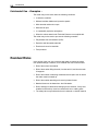
Intended Use
Adhesive melters of the series VersaBlueR may be used only to melt and
convey suitable materials, e.g. thermoplastic hot melt adhesives.
Any other use is considered to be unintended. Nordson will not be liable for
personal injury or property damage resulting from unintended use.
Intended use includes the observance of Nordson safety instructions.
Nordson recommends obtaining detailed information on the materials to be
used.
Area of Use (EMC)
In regard to electromagnetic compatibility (EMC), the melter is intended for
use in industrial applications.
Operating Restrictions
When operated in residential or commercial areas, the melter may cause
interference in other electrical units, e.g. radios.
E 2007 Nordson Corporation
VBC_Siemens
P/N 7135049A
2-2
Introduction
Unintended Use − Examples −
The melter may not be used under the following conditions:
S In defective condition
S Without insulation blanket and protective panels
S With electrical cabinet door open
S With tank lid open
S In a potentially explosive atmosphere
S When the values stated under Technical Data are not complied with.
The melter may not be used to process the following materials:
S Polyurethane hot melt adhesive (PUR)
S Explosive and flammable materials
S Erosive and corrosive materials
S Food products.
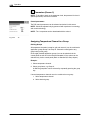
Residual Risks
In the design of the unit, every measure was taken to protect personnel
from potential danger. However, some residual risks can not be avoided:
S Risk of burns from hot material.
S Risk of burns when filling the tank, from the tank lid, and from the tank
lid supports.
S Risk of burns when conducting maintenance and repair work for which
the melter must be heated up.
S Risk of burns when attaching and removing heated hoses.
S Material fumes can be hazardous. Avoid inhalation.
S Risk of damage to cables/lines belonging to the customer, if they were
installed such that they come into contact with hot or rotating parts.
S The safety valve may malfunction due to hardened or charred material.
P/N 7135049A
VBC_Siemens
E 2007 Nordson Corporation
Introduction
2-3
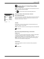
Definition of Terms
Interface Standard I/O
Component designation: XS 2
Transmits the digital input and output signals between the parent machine
and the Nordson melter.
Interface Key-to-line Mode
Component designation: XS 5 (one line speed signal input for all motors)
XS 5.1, XS 5.2, XS 5.3 and XS 5.4 (option: separate line speed signal
inputs).
NOTE: Key-to-line is also referred to as Automatic mode in Nordson
literature.
In key-to-line the motor/pump speed is regulated synchronously to the
speed of the parent machine.
The types described in this manual can be operated in key-to-line mode
with a line speed voltage of 0 − 10 VDC.
Encoder
The encoder compiles the line speed of the parent machine. It supplies a
certain number of electrical pulses per revolution. The frequency is a
measure of line speed.
CAUTION: The cable length may not be modified; this could cause
incorrect evaluation of the line speed, resulting in incorrect material
applications.
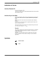
Symbols
Nordson default
Reset
E 2007 Nordson Corporation
VBC_Siemens
P/N 7135049A
2-4
Introduction
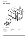
Melter Description
1
2
3
4
5
6
9
8
10
15
7
11
13
12
14
Fig. 2-1
1
2
3
4
5
6
Example VBC−200
Tank lid
Air filter
Control panel
Main switch
Motor circuit switch
Electrical cabinet
P/N 7135049A
7
8
9
10
11
Fan
Receptacles
Protective panel
Insulation blanket
Tank
VBC_Siemens
12
13
14
15
Safety valve plate
Gear pump
Motor
Coupling
E 2007 Nordson Corporation
Introduction
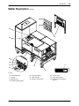
Melter Description
2-5
(contd.)
Ni120
Pt 100
25
16
24
23
22
21
17
19
20
18
Fig. 2-2
16
17
18
19
Hose receptacles
ID plate
Machine foot
Pressure gauge (option)
E 2007 Nordson Corporation
20 Hose (accessory)
21 Filter cartridge
22 Pressure control valve
VBC_Siemens
23 Air relief valve
24 Filling valve (option)
25 Recirculation connections
(option)
P/N 7135049A
2-6
Introduction
Melter Description
(contd.)
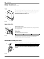
Tank
The tank is divided into grid (low melt) and reservoir (high melt) sections. An
insulating seal (2) provides a temperature barrier between the two sections.
The temperature barrier allows the material in the grid section (1) to be
gently melted at a low temperature. The material is then melted to
processing temperature in the reservoir (3).
1
2
3
Fig. 2-3
Safety Valve Plate
1
2
Tank Isolation Valve
The tank isolation valve (1) enables replacement of the gear pump without
first emptying the tank.
Safety Valve
The standard safety valve (2) is fixed at
8500 kPa
Fig. 2-4
85 bar
1235 psi
When the pressure is exceeded, the safety valve opens, allowing the
material to circulate within the safety valve plate.
Mechanical Pressure Control Valve
1
The mechanical pressure control valves (1) are built into the manifold above
the filter cartridge. They can be adjusted manually within the range of
500 to 9000 kPa
5 to 90 bar
72.5 to 1305 psi
One pressure control valve per pump is standardly installed after the filter
cartridge.
Fig. 2-5
P/N 7135049A
VBC_Siemens
E 2007 Nordson Corporation
Introduction
2-7
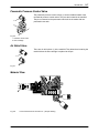
Pneumatic Pressure Control Valve
The pneumatic pressure control valves (1) can be installed instead of the
mechanical pressure control valves. They are also located in the manifold.
They are connected to the pneumatic control unit in the melter with one
pneumatic hose each.
1
2
Fig. 2-6
1 Pressure control valve
2 Filter cartridge
Air Relief Valve
There are air relief valves (1) in the manifold. They allow the air entering the
manifold when the filter cartridge is replaced to escape.
1
Fig. 2-7
Material Flow
Fig. 2-8
Cross-sectional view of the reservoir − principle drawing
E 2007 Nordson Corporation
VBC_Siemens
P/N 7135049A
2-8
Introduction
Melter Description
(contd.)
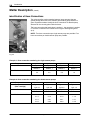
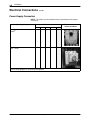
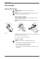
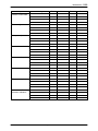
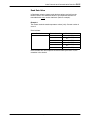
Identification of Hose Connections
The melter supplies various material streams (pump streams) that are
guided through the hoses to the different gear metering pump stations or
guns. Engraved numbers identify the hose connections so that the pump
streams can be correctly paired with the hoses.
The hose connection that leads down is number 1, the one above it number
2. The hose connections are numbered from right to left beginning with 1
(to 4).
NOTE: Two hose connections per single-stream pump are possible. Four
hose connections per double-stream pump are possible.
2
1
Fig. 2-9
Example 1: Hose connection numbering for single-stream pumps
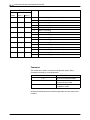
Pump number
4
3
2
1
Numbers
Top: 2
Top: 2
Top: 2
Top: 2
Bottom: 1
Bottom: 1
Bottom: 1
Bottom: 1
4.1
3.1
2.1
1.1
4.2
3.2
2.2
1.2
Possible hose connections
Example 2: Hose connection numbering for double-stream pumps
Pump number
4
3
2
1
Pump stream
(filter cartridge)
Right: 4.1
Right: 3.1
Right: 2.1
Right: 1.1
Left: 4.2
Left: 3.2
Left: 2.2
Left: 1.2
Numbers
Top: 2
Top: 2
Top: 2
Top: 2
Bottom: 1
Bottom: 1
Bottom: 1
Bottom: 1
4.1.1
3.1.1
2.1.1
1.1.1
4.1.2
3.1.2
2.1.2
1.1.2
4.2.1
3.2.1
2.2.1
1.2.1
4.2.2
3.2.2
2.2.2
1.2.2
Possible hose connections
P/N 7135049A
VBC_Siemens
E 2007 Nordson Corporation
Introduction
2-9
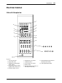
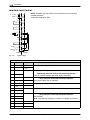
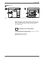
Electrical Cabinet
Side with Receptacles
1
2
3
5
4
7
4
6
8
6
8
9
10
11
12
Fig. 2-10
1 Air run-up, XS 32.n
2 Key-to-line, XS 5
3 Separate line speed signal
inputs, XS 5.n
4 Pneumatic pressure control /
bypass control, XS 4, XS 4.1
5 Pressure switch, XS 31.n
E 2007 Nordson Corporation
6
7
8
9
10
Standard I/O, XS 2, XS 2.1
Cable duct, XS D
Level control, XS 3, XS 3.1
Motors, n.XS 1
External heating zones XS 31 to
XS 35 (Pt 100 / Ni 120)
VBC_Siemens
11 External heating zones XS 26 to
XS 30 (Pt 100 / Ni 120)
12 Cable gland Power supply
P/N 7135049A
2-10 Introduction
Options
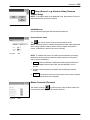
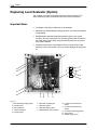
Level Control / Overflow Protection
3
2
The long level sensor (1) is connected to the analog level display and
transmits filling signals to a filling valve.
The short level sensor (2) serves as separate overflow protection. The
signal is made available to the customer for further evaluation at the
interface Level control. It is not evaluated by the PLC. The signal must be
acknowledged. Refer to Troubleshooting, Overflow protection is activated...
1
The filling valve (3) for automatic tank filling is located on the tank.
The filling valve control module opens when the solenoid valve is triggered.
The material is conveyed into the melter tank, e.g. by a bulk melter.
1
2
Fig. 2-11
P/N 7135049A
VBC_Siemens
E 2007 Nordson Corporation
Introduction
Options
2-11
(contd.)
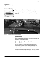
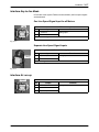
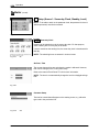
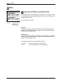
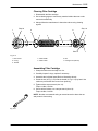
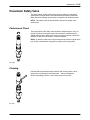
Pressure Display
The pressure sensors (Fig. 2-12 and 2, Fig. 2-13) for material outlet
pressure are located in the hose connections. The corresponding
measuring transducers (2) are located below the manifold. The last
pressure sensor along the bus must be equipped with a terminating
resistor (3).
Fig. 2-12
1
Fig. 2-13
1
3
2
Pressure sensors in the hose connections
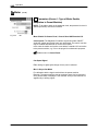
Pressure Display
Each pump stream is equipped with a pressure sensor for the pressure
display in systems with only double-stream pumps and in systems with both
single-stream and double-stream pumps.
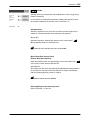
Pressure Display and Pressure Control
Pressure Build-up
The single-stream pump is equipped with a pressure sensor for the
pressure display and control in systems with both single-stream and
double-stream pumps. In the double-stream pump each pump stream is
equipped with a pressure sensor for the pressure display. However, only
one each is used for pressure control.
In systems consisting only of double-stream pumps, each pump is equipped
with two pressure sensors for the pressure display. However, only one each
is used for pressure control.
E 2007 Nordson Corporation
VBC_Siemens
P/N 7135049A
2-12 Introduction
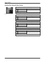
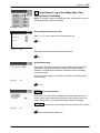
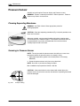
ID Plate
The system has two ID plates. One is located on the outside of the melter
(Refer to Fig. 2-2), and the other is in the electrical cabinet.
VersaBlue 1
2
ADHESIVE MELTER
3
UL
C
US
LISTED
4
Serial No:
5
Year
Nordson Engineering GmbH
Lilienthalstr. 6
D 21337 Lüneburg − Germany
www.nordson.com
Fig. 2-14
1
Melter designation
2
Order number
3
Configuration code
4
Electrical connection, operating voltage, line voltage frequency, melter fuse protection
5
Serial number
P/N 7135049A
VBC_Siemens
E 2007 Nordson Corporation
Installation
3-1
Section 3
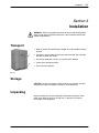
Installation
WARNING: Allow only qualified personnel to perform the following tasks.
Observe and follow the safety instructions in this document and all other
related documentation.
Transport
S Refer to section Technical Data for weight. Use only suitable transport
devices.
1
S If possible, use the pallet (2) that came with the melter and use angle
brackets to fasten the melter.
S Use sturdy cardboard or a box (1) to protect from damage.
2
S Protect from humidity and dust.
S Avoid jolts and vibrations.
Fig. 3-1
Storage
CAUTION: Do not store melter outside! Protect from humidity, dust and
extreme temperature fluctuations (formation of condensation).
Unpacking
Unpack carefully and check for damage caused during transport. Save
pallet, angle brackets and box for later use, or dispose of it properly
according to local regulations.
E 2007 Nordson Corporation
VBC_Siemens
P/N 7135049A
3-2
Installation
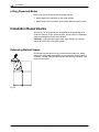
Lifting (Unpacked Melter)
Refer to the section Technical Data for weight. Lift only
S With suitable lifting equipment on the melter chassis
S With a forklift. There are tracks for the forklift under the melter chassis.
Installation Requirements
Set up only in an environment that corresponds to the stated Degree of
Protection (Refer to section Technical Data). Do not mount in a potentially
explosive atmosphere! Protect from vibration.
CAUTION: Protect the control panel from direct sunlight. The UV rays
reduce the service life of the liquid crystals.
Exhausting Material Vapors
Ensure that material vapors do not exceed the prescribed limits. Always
observe the safety data sheet (MSDS) for the material to be processed. If
necessary, exhaust material vapors and provide sufficient ventilation of the
location of the system.
Fig. 3-2
P/N 7135049A
VBC_Siemens
E 2007 Nordson Corporation
Installation
3-3
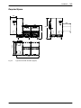
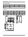
Required Space
660
900
2100
1395
1300
1350
2400
Fig. 3-3
Type VB C with tank extension (hopper)
E 2007 Nordson Corporation
VBC_Siemens
P/N 7135049A
3-4
Installation
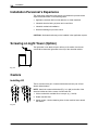
Installation Personnel’s Experience
The instructions contained in this section are intended for personnel with
experience/authorization in the following fields:
S Application methods with hot melt adhesive or similar materials
S Industrial electrical wiring of power and control lines
S Industrial mechanical installation
S General knowledge of process control.
CAUTION: Illuminated seals may not be installed in the application system.
Screwing on Light Tower (Option)
The light tower is not attached upon delivery of the melter. Use the two
screws M5 to fasten the light tower to the top of the electrical cabinet.
Fig. 3-4
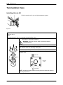
Casters
Installing Kit
The kit consists of two pair of casters with brakes and one pair of fixed
wheels without brakes.
NOTE: Attach the casters with brakes (Fig. 3-5, right) to the side of the
electrical cabinet and in the center of a twin tank unit.
1. Lift the melter with a suitable floor conveyor (e.g. fork lift).
2. Detach machine feet.
3. Attach casters. Use the fastening holes for the machine feet to attach
the casters.
Fig. 3-5
P/N 7135049A
VBC_Siemens
E 2007 Nordson Corporation
Installation
3-5
Electrical Connections
WARNING: Risk of electrical shock. Failure to observe may result in
personal injury, death, or equipment damage.
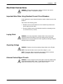
Important Note When Using Residual Current Circuit Breakers
Local regulations in some industrial branches require residual current circuit
breakers.
Then observe the following points:
S Residual current circuit breakers are to be installed only between the
power supply and the melter.
S Use only residual current circuit breakers sensitive to pulsating current
or universal current (> 30 mA).
Laying Cable
WARNING: Use only temperature resistant cable in warm areas of the
equipment. Ensure that cables do not touch rotating and/or hot melter
components. Do not pinch cables and check regularly for damage. Replace
damaged cables immediately!
Operating Voltage
WARNING: Operate only at the operating voltage shown on the ID plate.
NOTE: Permitted deviation from the rated line voltage is 10%.
NOTE: The power cable cross-section must comply with the maximum
power consumption (refer to section Technical Data ).
External Control/Signal Circuits
WARNING: Connect external control and signal circuits with suitable cable
in accordance with the NEC, class 1. To prevent short-circuiting, lay the
cables such that they do not touch printed circuits on PCBs.
E 2007 Nordson Corporation
VBC_Siemens
P/N 7135049A
3-6
Installation
Electrical Connections
(contd.)
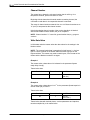
Power Supply Connection
NOTE: The melter must be installed securely (permanent power supply
connection).
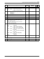
Terminals
Operating voltage
L1
L2
L3
230 VAC 3-phase without neutral
(Delta)
D
D
D
400 VAC 3-phase with neutral
(star − WYE)
D
D
D
N
PE
Mains terminals in
electrical cabinet
D
D
D
Refer to wiring diagram for connecting arrangement.
P/N 7135049A
VBC_Siemens
E 2007 Nordson Corporation
Installation
3-7
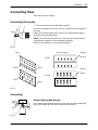
Connecting Hose
Also refer to the hose manual.
Connecting Electrically
1 2
3
1. First connect the hose (3) electrically to the unit.
Use hose receptacles XS10 to XS17 (Fig. 3-7, bottom row) for the plugs of
the hoses.
If there are more than eight hoses, use the hose receptacles XS 26(a) to
XS 35(a) on the electrical cabinet.
NOTE: For more than one hose: Every hose connection is allocated to a
corresponding receptacle. Do not mistakenly exchange!
Refer to wiring diagram for connecting arrangement.
Fig. 3-6
Melter
Electrical cabinet
Ni 120
-XS17
-XS10
-XS 26.a
...
-XS 35.a
-XS 26
...
-XS 35
Pt 100
-XS17
-XS10
Fig. 3-7
Connecting
Second Open-jawed Wrench
Use a second open-jawed wrench when connecting and disconnecting the
hose. This prevents the unit’s hose connection from turning.
MXHH002S033A0295
Fig. 3-8
E 2007 Nordson Corporation
VBC_Siemens
P/N 7135049A
3-8
Installation
Connecting
(contd.)
NOTE: For units with recirculation hoses: do not mistake recirculation
hoses for feed hoses.
1 2
3
If cold material can be found in the hose connection, the components (1, 2)
must be heated until the material softens (approx. 70 °C (158 °F),
depending on material.
WARNING: Hot! Risk of burns. Wear heat-protective gloves.
2. Heat the melter and hose to approx. 70 °C (158 °F).
CAUTION: Close unused hose connections with Nordson port plugs.
Fig. 3-9
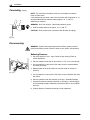
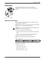
Disconnecting
WARNING: System and material pressurized. Relieve system pressure
before disconnecting hoses. Failure to observe can result in serious burns.
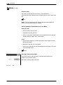
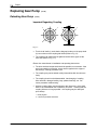
Relieving Pressure
1
1. Set motor speed to 0 min-1 (rpm). Switch off the motor(s) (Refer to
section Operation ).
2. Place a container under the air relief valves (1, Fig. 3-10) to be opened.
3. Use a screwdriver to turn the air relief valve screws counterclockwise
and open the valves.
4. Material flows out of the air relief hole, and the melter is relieved of
pressure.
Fig. 3-10
5. Use a screwdriver to turn the air relief valve screws clockwise and close
the valves.
6. Place a container under the nozzle(s) of the gun / assembly handgun.
7. Activate the solenoid valve(s) electrically or manually, or pull the trigger
of the assembly handgun. Repeat this procedure until no more material
flows out.
8. Properly dispose of material according to local regulations.
P/N 7135049A
VBC_Siemens
E 2007 Nordson Corporation
Installation
3-9
Connecting Filling Valve (Option)
Conditioning Compressed Air
The quality of the compressed air must be at least class 2 in compliance
with ISO 8573−1. This means:
S Max. particle size 30 mm
S Max. particle density 1 mg/m3
S Max. pressure dew point − 40 °C
S Max. oil concentration 0.1 mg/m3.
1
2
1. Connect customer’s compressed air supply to the control air connection
(2).
4 to 6 bar
400 to 600 kPa
58 to 87 psi
2. Electrically/mechanically connect hose to the filling unit.
3. Connect hose to filling valve connection (1) (Refer to illustration).
The filling valve is heated either via the VersaBlue melter or via the filling
unit (e.g. bulk melter).
4. If heating does not occur via the VersaBlue melter, insert the electrical
plug (cordset) into the hose receptacle.
Fig. 3-11
E 2007 Nordson Corporation
VBC_Siemens
P/N 7135049A
3-10 Installation
Interface Assignment
Interface Standard I/O − Standard Assignment for XS 2 −
General Information
Inputs
Outputs
S To conform with a European standard regarding electro-magnetic
compatibility (EMC), only shielded cable may be connected. The cable
must be connected to ground in compliance with the standard regarding
electromagnetic compatibility.
S Inductive loads (e.g. solenoid valves) connected to the melter must be
equipped with a protective device (e.g. recovery diode) that disables the
inductive voltage generated when an inductive load is switched off.
S The permitted voltage deviation is 10%.
S In Field bus mode (option Field bus communication) the unit can not be
controlled via the interface.
Digital inputs
Pin
Input
Function
1*
24 VDC
Internal (melter)
2*
0 VDC
External (customer’s)
NOTE: Customer connects his reference potential here, if 24 VDC is provided by
customer.
3
24 V
Rising edge: Heaters ON (main contactor closes)
0V
Falling edge: Heaters OFF (main contactor opens)
24 V
0V
4
24 V: Both motors ON (collective enable)
0 V: Both motors OFF
5
24 V: Enable Motor 1
0 V: No Motor 1 enable
6
24 V: Enable Motor 2
0 V: No Motor 2 enable
9
24 V
Rising edge: Switch on Standby
0V
Falling edge: Switch off Standby
24 V
0V
10
24 V
Rising edge: Key-to-line mode (for both motors)
0V
Falling edge: Manual mode (for both motors)
24 V
0V
* optional
P/N 7135049A
VBC_Siemens
E 2007 Nordson Corporation
Installation
3-11
Digital inputs
Pin
Input
11
Function
24 V
Rising edge: Switch application group to control mode (input 1)
0V
24 V
0V
Falling edge: Switch application group to standby or
Falling edge: Deactivate application group
(Standby or Deactivate is dependent on the function selected on the control panel,
refer to section Operation, Working with Application Groups, Setup, Selecting Feature )
12
Like pin 11 (input 2)
13
Like pin 11 (input 3)
14
Like pin 11 (input 4)
15
Line started / stopped
Pin 7, 8, 16 not assigned
NOTE: Contact rating max. 24 VDC/2 A
Digital outputs
Pin
17
Contact
Function
Make
contact
Contact closed: Motor 1 running
Contact open: Motor 1 not running
Make
contact
Contact closed: Motor 2 running
Contact open: Motor 2 not running
25
24 VDC
External (customer’s; to be connected by customer)
26
Make
contact
24 V: System ready
0 V: System not ready
27
Break
contact
24 V: No general alarm −warning−
0 V: General alarm −warning−
28
Break
contact
24 V: No general alarm −fault−
0 V: General alarm −fault−
18
19
20
Pin 29 not assigned
30
Break
contact
Pressure buildup completed
31
Make
contact
Contact closed: Fill tank
Contact open: Do not fill tank
32
NOTE: Pins 31 and 32 are not assigned with the options Level control and Level
control with overflow protection. Instead, there is the interface Level control.
Pin 21, 22, 23, 24 not assigned
E 2007 Nordson Corporation
VBC_Siemens
P/N 7135049A
3-12 Installation
Interface Standard I/O − Standard Assignment for XS 2.1 −
Digital inputs
Pin
Input
Function
1*
24 VDC
Internal (melter)
2*
0 VDC
External (customer’s)
NOTE: Customer connects his reference potential here, if 24 VDC is provided by
customer.
5
24 V: Enable Motor 5
0 V: No Motor 5 enable
6
24 V: Enable Motor 6
0 V: No Motor 6 enable
9
24 V: Enable Motor 7
0 V: No Motor 7 enable
10
24 V: Enable Motor 8
0 V: No Motor 8 enable
11
24 V: Enable External motors
0 V: No External motors enable
Pins 3, 4, 7, 8, 12 to 16 not assigned
* optional
P/N 7135049A
VBC_Siemens
E 2007 Nordson Corporation
Installation
3-13
Standard I/O Interface − XS2 Assignment with
Option Solenoid Valve Control −
Digital inputs
Pin
Input
Function
1*
24 VDC
Internal (melter)
2*
0 VDC
External (customer’s)
NOTE: Customer connects his reference potential here, if 24 VDC is provided by
customer.
3
24 V
Rising edge: Heaters ON (main contactor closes)
0V
Falling edge: Heaters OFF (main contactor opens)
24 V
0V
4
24 V: All motors ON (collective enable)
0 V: All motors OFF
5
24 V: Enable Motor 1
0 V: No Motor 1 enable
6
24 V: Enable Motor 2
0 V: No Motor 2 enable
9
24 V
Rising edge: Switch on Standby
0V
Falling edge: Switch off Standby
24 V
0V
10
24 V
Rising edge: Key-to-line mode (for all motors)
0V
Falling edge: Manual mode (for all motors)
24 V
0V
11
24 V
Rising edge: Switch application group to control mode (input 1)
0V
24 V
0V
Falling edge: Switch application group to standby or
Falling edge: Deactivate application group
(Standby or Deactivate is dependent on the function selected on the control panel,
refer to section Operation, Working with Application Groups, Setup, Selecting Feature )
12
Like pin 11 (input 2)
13
Like pin 11 (input 3)
14
Like pin 11 (input 4)
15
Line started / stopped
Pin 7, 8, 16 not assigned
* optional
NOTE: Contact rating max. 24 VDC/2 A
E 2007 Nordson Corporation
VBC_Siemens
P/N 7135049A
3-14 Installation
Digital outputs
Pin
17
Contact
Function
Make
contact
24 V: External solenoid valve 1 is triggered
0 V: External solenoid valve 1 is not triggered
Make
contact
24 V: External solenoid valve 2 is triggered
0 V: External solenoid valve 2 is not triggered
25
24 VDC
External (customer’s; to be connected by customer)
26
Make
contact
24 V: System ready
0 V: System not ready
27
Break
contact
24 V: No general alarm −warning−
0 V: General alarm −warning−
28
Break
contact
24 V: No general alarm −fault−
0 V: General alarm −fault−
18
19
20
Pin 29 not assigned
30
Break
contact
Pressure buildup completed
31
Make
contact
Contact closed: Fill tank
Contact open: Do not fill tank
32
NOTE: Pins 31 and 32 are not assigned with the options Level control and Level
control with overflow protection. Instead, there is the interface Level control.
Pin 21, 22, 23, 24 not assigned
NOTE: Contact rating max. 24 VDC/2 A
Digital outputs
Pin
17
18
19
20
21
22
23
24
Contact
Function
Make
contact
Contact closed: Motor 5 running
Contact open: Motor 5 not running
Make
contact
Contact closed: Motor 6 running
Contact open: Motor 6 not running
Make
contact
Contact closed: Motor 7 running
Contact open: Motor 7 not running
Make
contact
Contact closed: Motor 8 running
Contact open: Motor 8 not running
Pins 25 to 32 not assigned
P/N 7135049A
VBC_Siemens
E 2007 Nordson Corporation
Installation
3-15
Interface Standard I/O − XS2.1 Assignment with
Option Solenoid Valve Control −
Digital inputs
Pin
Input
Function
1*
24 VDC
Internal (melter)
2*
0 VDC
External (customer’s)
NOTE: Customer connects his reference potential here, if 24 VDC is provided by
customer.
Pin 3 not assigned
Pin 4 not assigned
5
24 V: Enable Motor 5
0 V: No Motor 5 enable
6
24 V: Enable Motor 6
0 V: No Motor 6 enable
Pin 7 not assigned
Pin 8 not assigned
9
24 V: Enable Motor 7
0 V: No Motor 7 enable
10
24 V: Enable Motor 8
0 V: No Motor 8 enable
11
External motors’ collective enable
Pins 12 to 16 not assigned
* optional
NOTE: Contact rating max. 24 VDC/2 A
Digital outputs
Pin
17
18
19
20
21
22
23
24
Contact
Function
Make
contact
24 V: External solenoid valve 5 is triggered
0 V: External solenoid valve 5 is not triggered
Make
contact
24 V: External solenoid valve 6 is triggered
0 V: External solenoid valve 6 is not triggered
Make
contact
24 V: External solenoid valve 7 is triggered
0 V: External solenoid valve 7 is not triggered
Make
contact
24 V: External solenoid valve 8 is triggered
0 V: External solenoid valve 8 is not triggered
Pins 25 to 32 not assigned
E 2007 Nordson Corporation
VBC_Siemens
P/N 7135049A
3-16 Installation
Interface Gun Solenoid Valve Control
XS1.1 to XS8.1 (3-pin)
−XS1.1
Pin
Output
1
− (Ground)
2
24 VDC
Function
Digital output
Pin 3 not assigned
Fig. 3-12
XS1.2 to XS8.2 (3-pin)
Pin
Output
1
− (Ground)
2
24 VDC
Function
Digital output via XS 2
Pin 3 not assigned
XS1.3 to XS8.3 (3-pin)
Pin
Output
1
− (Ground)
2
24 VDC
Function
Digital output via XS 2
Pin 3 not assigned
XS1.4 to XS8.4 (3-pin)
Pin
Output
1
− (Ground)
2
24 VDC
Function
Digital output via XS 2
Pin 3 not assigned
P/N 7135049A
VBC_Siemens
E 2007 Nordson Corporation
Installation
3-17
Interface Key-to-line Mode
In Field bus mode (option Field bus communication ) the line speed signals
are deactivated.
One Line Speed Signal Input for all Motors
XS5
−XS5
Pin
Input
1
− (Ground)
2
0 to 10 V
Function
Analog input
Pin 3 to 5 not assigned
Fig. 3-13
Separate Line Speed Signal Inputs
XS5.1 to XS 5.2 (3-pin)
Pin
−XS5.n
Input
1
− (Ground)
2
0 to 10 VDC
Function
Analog input
Pin 3 not assigned
Fig. 3-14
Interface Air run-up
XS32.1 to 32.16
−XS32.n
Pin
E 2007 Nordson Corporation
Output
1
24 V
2
0 to 10 V
3
− (Ground)
Function
Analog output
VBC_Siemens
P/N 7135049A
3-18 Installation
Interface Level Control
0 - 10 VDC
0 VDC
NOTE: Available only with options Level control and Level control with
overflow protection.
16
15
14
Component designation: XS3
13
11
12
10
9
8
7
6
5
0 VDC
4
3
*)
2
1
+24 VDC
internal
Fig. 3-15
external
Default bridges
Digital inputs/outputs
Pin
Input
Output
Function
1
−
24 VDC
2
−
0 VDC
3
−
24 VDC / 2 A
4
−
5
−
−
6
−
−
− Only with level control with overflow protection −
Reset (resets signal Tank is overfilled)
7
+24 VDC
−
Voltage supply to filling valve
8
0 VDC
−
9
−
24 VDC / 2 A
Fill tank
10
−
11
−
24 VDC / 2 A
12
−
13
−
− Only with level control with overflow protection −
Tank overfilled
NOTE: Potential-free changeover contact for evaluation by customer
14
−
0 − 10 V
Analog value level control
15
−
Ground
16
−
Screen
P/N 7135049A
Internal voltage supply of separate overflow protection
Fill tank signal to filling valve
− Additionally with level control with overflow protection −
*) Tank is overfilled (contact open when level is exceeded)
VBC_Siemens
E 2007 Nordson Corporation
Installation
3-19
Removing Melter
Run the melter until empty, separate all connections from the melter, and
allow the melter to cool down.
Disposing of Melter
When your Nordson product has exhausted its purpose, dispose of it
properly according to local regulations.
E 2007 Nordson Corporation
VBC_Siemens
P/N 7135049A
3-20 Installation
P/N 7135049A
VBC_Siemens
E 2007 Nordson Corporation
Operation
4-1
Section 4
Operation
WARNING: Allow only qualified personnel to perform the following tasks.
Observe and follow the safety instructions in this document and all other
related documentation.
General Information
The control panel is a touch screen.
Meaning of Colors
E 2007 Nordson Corporation
Red:
Fault
Yellow:
Display of e.g. status, actual values. Also a warning in status
line
Green:
Adjustable values: Input of e.g. setpoints/text or switched on
Gray:
Selection (with keys) is possible
VBC_Siemens
P/N 7135049A
4-2
Operation
Description of Symbols
The following symbols appear on several screens and indicate
Call up a help text
General information
ESC
windows
Return to previous level. Cancel and close when in input
To next/previous screen
Confirmation, acceptance of a value
Backspace, delete
Page up/down
Setup
Master overwrite
P/N 7135049A
VBC_Siemens
E 2007 Nordson Corporation
Operation
4-3
Keys with and without Indication Lamp
The indication lamp indicates the status (lit = switched on). In this case:
Heaters are switched on.
Fig. 4-1
Example
Input Window
When a field for entering a numerical value is touched, this input window
appears.
Fig. 4-2
When a field for entering a name is touched, this input window appears.
E 2007 Nordson Corporation
VBC_Siemens
P/N 7135049A
4-4
Operation
Status Display
Another screen is called up by touching the line Status display. The contents
of the screen is a factor of the displayed status:
Status display
S Heatup phase
S System ready
S Startup protection or standby
S Motor running or heaters off.
Heatup phase
Remaining time until system
ready
3
0
20 min
Heating hours until next
maintenance
0
min
By status
S Warning
500
h
500 h
S Fault
S Shutdown
the system moves directly to Fault indications (Refer to Fig. 4-29).
System ready
Time until automatic enter standby
after motor stop
13 min
0
15 min
Heating hours until next
maintenance
0
500
h
500 h
Startup protection
Time until automatic enter standby
after motor stop
13 min
0
15 min
Heating hours until next
maintenance
0
500
h
500 h
Standby
Time until manual standby duration expires
0
9
min
10 min
Heating hours until next
maintenance
0
500
h
500 h
Heaters off
Heating hours until next
maintenance
0
P/N 7135049A
500
h
500 h
VBC_Siemens
E 2007 Nordson Corporation
Operation
4-5
Initial Startup
After the melter has been properly installed, initial startup can take place.
The melter was subjected to extensive testing prior to shipment. In doing so,
the tank was filled with a special test material. Material residue may still be
present in the melter. To remove the residue, melt and feed several
kilograms of material before starting production.
CAUTION: Do not operate Nordson gear pumps without material. Before
switching on the motor, ensure that the tank is filled.
1. Set the main switch to I/ON.
Position I/ON
= Melter switched on.
Position 0/OFF
= Melter switched off.
Padlocks can be used to protect the main switch from being turned on by
unauthorized personnel.
2. Wait until the starting screen appears on the control panel.
NOTE: Do not touch or cover the screen during startup. Wait until it has
completed the function test and the light tower lamp test and the starting
screen appears.
Fig. 4-3
Starting screen
E 2007 Nordson Corporation
VBC_Siemens
P/N 7135049A
4-6
Operation
Entering Password
If a password-protected input field is touched, the control unit causes the
keypad and the input field for the password to appear.
Fig. 4-4
The default setting is two password levels with the following passwords:
S S Operator: 747
S S Engineer: 757
Change the passwords upon initial startup.
Also refer to Siemens Manual TP 270, Password Protection.
P/N 7135049A
VBC_Siemens
E 2007 Nordson Corporation
Operation
Initial Startup
4-7
(contd.)
Set on Control Panel:
3. Basic settings
2
3
Fig. 4-5
Touch repeatedly until the starting screen reappears.
Control Panel Setup
NOTE: If the key is touched unintentionally, the following screen appears
on the control panel.
S Reply NO and return to the program.
If YES is confirmed, the PLC begins the operating program again
(restart/reboot). The operator must now wait until a screen appears that
contains a key F8. The key must be pressed so that the starting screen is
displayed again. This takes approx. three to five minutes.
Fig. 4-6
Refer to the manual Touch Panel TP 270 for more information.
S Temperature setpoints (= processing temperatures)
Refer to Overview / T1.
S Undertemperatures / overtemperatures
Refer to Overview / T2.
E 2007 Nordson Corporation
VBC_Siemens
P/N 7135049A
4-8
Operation
Control Panel Setup (contd.)
S Activate/deactivate channels
S Re-name temperature channels if necessary.
NOTE: Texts that the customer can change are not translated into
the selected local language.
Refer to Overview / T3.
S Pump speed(s) in manual mode
NOTE: To prevent excessive wear, the motor/pump speed should
not continuously fall below 5 min-1 (rpm) or continuously exceed
80 min-1 (rpm).
Refer to Overview / M1.
S If the melter is to be operated via the interface Standard I/O, change
the motor enable from Control panel to Control panel AND standard
I/O.
Refer to Overview / M2
S Key-to-line − settings
Refer to Overview / M1 to M3.
S Select temperature unit, °C (default) or °F
Select pressure unit, bar (default) or psi
Refer to Overview / V15
P/N 7135049A
VBC_Siemens
E 2007 Nordson Corporation
Operation
Initial Startup
4-9
(contd.)
S Set service interval.
The service tasks that are to be indicated as well as the intervals
must be stipulated. For recommended intervals refer to section
Maintenance. The intervals may need to be adapted to the operating
conditions.
Refer to Overview / V16
S Additional parameters, depending on model of melter.
4. Set seven-day clock.
Refer to Overview / V8
System ready
5. Wait until the system is ready for operation.
Fig. 4-7
6. Tighten the gland bolt on the pump(s) (Refer to section Maintenance).
7. Enable the motor(s).
8. Switch on the motor(s).
Refer to Overview / M1 and V1 and Figure 4-28.
E 2007 Nordson Corporation
VBC_Siemens
P/N 7135049A
4-10 Operation
Control Panel − Overview −
Starting screen
T1
Tzone # n
T2
T3
T4
Fig. 4-8
Note:
The feature Self-optimization is available only with melters that have ETR temperature controllers. The
menu T4 is not available with melters that have ETR temperature controllers.
P/N 7135049A
VBC_Siemens
E 2007 Nordson Corporation
Operation
Control Panel − Overview −
4-11
(contd.)
Starting screen
V1
"V7
Working with Application Groups
V2
V5
V3
V6
V4
Fig. 4-9
E 2007 Nordson Corporation
VBC_Siemens
P/N 7135049A
4-12 Operation
Control Panel − Overview −
(contd.)
V1
V7
"V14
V8
V9
V10
V11
V12
V13
Fig. 4-10
P/N 7135049A
VBC_Siemens
E 2007 Nordson Corporation
Operation
Control Panel − Overview −
4-13
(contd.)
V7
V14
V19
Pressure sensor
setup
System ready setup
V17
V20
V16
V20.1
V15
Fieldbus setup
V18
Fig. 4-11
E 2007 Nordson Corporation
VBC_Siemens
P/N 7135049A
4-14 Operation
Control Panel − Overview −
(contd.)
Starting
screen
M1
M3
Motor 1
M2
One line
speed signal
for all motors
M4
M6
M5
Pressure
sensor C
M6.1
With pressure build-up function
M8
M7
PID parameters
Fig. 4-12
P/N 7135049A
VBC_Siemens
E 2007 Nordson Corporation
Operation
4-15
Filling the Tank
Manually
WARNING: Hot! Risk of burns. Wear appropriate protective
clothing/equipment. Tank and tank lid are hot. When filling, hot material may
splash out of the tank. Use caution when filling tank with material.
CAUTION: Do not operate melter with open tank. When the tank is open,
hot material vapors can escape; vapors may contain potentially hazardous
substances.
CAUTION: Before filling the tank, ensure that the tank and material are
clean and free of foreign substances. Foreign substances can hinder
functioning or even cause damage to the melter or accessories.
Fig. 4-13
CAUTION: Cease operation before the tank is completely empty. If there is
too little material in the tank, the material can overheat. Overheated material
can char, collect on surfaces and cause malfunctioning.
E 2007 Nordson Corporation
VBC_Siemens
P/N 7135049A
4-16 Operation
Maximum Level
The level should not exceed 25 mm (1 inch) under the rim of the
tank (max1).
25 mm
max1
Fig. 4-14
Cross-section of
tank
Automatic (Option)
Automatic tank filling is performed e.g. by a bulk melter connected to the
optional filling valve with a hose. Level sensors in the tank start and stop the
filling process.
Fig. 4-15
P/N 7135049A
Filling valve
VBC_Siemens
E 2007 Nordson Corporation
Operation
4-17
Recommended Temperature Setpoints
The temperature setting is determined, among other things, by the
processing temperature prescribed by the material supplier.
CAUTION: Nordson will grant no warranty and assume no liability for
damage resulting from incorrect temperature settings.
Grid
Up to 20 °C (36 °F) below prescribed processing temperature
Reservoir (high melt)
Prescribed processing temperature
(Material quantity used <50 g/min: 0 to 10 °C (18 °F) below prescribed
processing temperature
Undertemperature value
(warning)
10 °C (18 °F) below set processing temperature
Undertemperature value
(fault)
15 °C (27 °F) below set processing temperature
Overtemperature value
(warning)
10 °C (18 °F) above set processing temperature
Overtemperature value (fault)
15 °C (27 °F) above set processing temperature
Air heater: approx. 10 °C (18 °F) below set processing temperature
Air heater: approx. 20 °C (36 °F) below set processing temperature
Air heater: approx. 10 °C (18 °F) above set processing temperature
Air heater: approx. 20 °C (36 °F) above set processing temperature
Filling valve (option)
Prescribed processing temperature*
Gun (accessory)
Prescribed processing temperature(s)*
Hose (accessory)
Prescribed processing temperature*
* CAUTION: The maximum operating temperature of the installed gun and the other heated system
components should be considered when setting temperatures on the melter control panel. Refer to Overview
/ T1 for information on input.
E 2007 Nordson Corporation
VBC_Siemens
P/N 7135049A
4-18 Operation
Heatup Guided by Reference Channel
NOTE: All activated channels in control mode are included in the heatup
guided by reference channel, including those assigned to an activated
application group.
After every switchon and after standby is exited, the melter returns to
Heatup phase (status display).
Heatup guided by reference channel prevents individual temperature
channels from reaching their setpoint temperature long before the slowest
temperature channel (reservoir/high melt = reference channel). It prevents
hot melt material from charring in hoses/guns and the build-up of material
expansion pressure during heatup. It also helps to save energy.
Temperature
Setpoint Guided channel
Setpoint Reference channel
The actual reservoir temperature serves as the current temperature setpoint
for the guided channels until the reservoir has reached a temperature of
10 °C (18 °F) below its setpoint temperature. Then heatup guided by
reference channel ends automatically. This way all channels reach their
setpoint temperatures more or less at the same time.
10 °C
Time
Fig. 4-16
When the current temperature setpoint of a guided channel (= current value
of reservoir/high melt) reaches the guided channel’s own setpoint minus
2 °C (3.6 °F), it is excluded from heatup guided by reference channel and
then heats to its own setpoint independently (Refer to Fig. 4-17).
Temperature
Setpoint Reference channel
Setpoint Guided channel
2 °C
Time
Fig. 4-17
P/N 7135049A
VBC_Siemens
E 2007 Nordson Corporation
Operation
4-19
Undertemperature Interlock
The undertemperature interlock prevents the melter motors from being
switched on as long as the material is too cold and thus too thick. This could
damage the pumps.
The undertemperature interlock is active during every Heatup phase (status
display) and after every standby. Also refer to section Troubleshooting,
Undertemperature Fault Triggered. If the system ready delay time is
activated, this time must also have expired before the interlock is disabled.
Motor Startup Protection
The motor startup protection prevents the motors from starting up on their
own after heatup or after a fault. The melter goes to startup protection if at
least one motor was running before heatup or before the fault occurred.
Condition for Motor running: All motors ON and Enable motor
When the system is ready again (status display), the motors can be
switched on again via the control panel or the interface Standard I/O.
Acknowledge Startup Protection
On the Control Panel
Press the key Switch on/off all motors (collective enable); startup
protection is acknowledged and all enabled motors run again.
Via Interface Standard I/O
Switch All motors ON/OFF from OFF to ON. All enabled motors run again.
Via Field Bus
Set All motors ON/OFF (collective enable). (rising edge; refer to Melter
control: If bit 1 = 0, then set to 1. If bit 1 = 1, set to 0 then back to 1). All
enabled motors are running again.
E 2007 Nordson Corporation
VBC_Siemens
P/N 7135049A
4-20 Operation
Daily Startup
NOTE: The following steps can be performed completely only with a level 1
password.
1. Set the main switch to I/ON.
2. If the heater is switched off, the
key may need to be touched. The
melter begins to heat up.
CAUTION: Do not operate Nordson gear pumps without material. Before
switching on the motor, ensure that the tank is filled.
3. Fill the tank if necessary.
4. Wait until the system is ready for operation (green status display System
ready).
5. Enable the motor(s). Refer to Fig. 4-28.
(Refer to Overview / M1 )
NOTE: To prevent excessive wear, the motor/pump speed should not
continuously fall below 5 min-1 (rpm) or continuously exceed 80 min-1 (rpm).
6. Switch on the motor(s). Refer to Fig. 4-28.
Daily Switchoff
1. Switch off the motor(s).
2. Set the main switch to 0/OFF.
3. If necessary, secure the main switch with padlocks against unauthorized
access.
Switching Off in an Emergency
WARNING: Switch off the melter immediately in any emergency situation.
1. Set the main switch to 0/OFF.
2. After standstill and before switching the melter on again, have the
emergency situation remedied by qualified personnel.
P/N 7135049A
VBC_Siemens
E 2007 Nordson Corporation
Operation
4-21
TP 270 Control Panel
Heatup phase
Fig. 4-18
Melter Modes − Overview
V25, V50, V 100
⇒
Local mode
⇒
⇒
⇒
Speed control
⇒
Speed control
D
Manual mode
D
Manual mode
D
Key-to-line
D
Key-to-line
Pressure control
E 2007 Nordson Corporation
Field bus mode
⇒
Pressure control
D
Manual mode
D
Manual mode
D
Key-to-line
D
Key-to-line
VBC_Siemens
P/N 7135049A
4-22 Operation
Starting Screen
Service symbol: A wrench lights up. Refer to Overview / V16.
Fig. 4-19
Additional screens are called up by pressing these symbols:
Move to the screen in which the setpoints can be entered for all
temperature channels (Refer to Overview / T1).
Move to melter screens
Move to motor screens
P/N 7135049A
VBC_Siemens
E 2007 Nordson Corporation
Operation
4-23
Temperature Parameters
CAUTION: The maximum operating temperature of the installed gun and
the other heated system components should be considered when setting
temperatures.
Left temperature column (yellow): Actual values
Right temperature column (green): Setpoints
NOTE: A channel is deactivated if the respective actual values are 0 (zero).
Fig. 4-20
T1
Grid and reservoir: 175 °C (347 °F)
Hose 1 / Gun 1: 175 °C (347 °F)
All other channels: 40 °C (100 °F)
Example: Increasing Temperature of Hose 1
from 220 °C (428 °F) to 230 °C (446 °F)
Fig. 4-21
1. Touch the green field 220 °C in the right temperature column (setpoints).
2. Enter 230 in the input window and confirm with
E 2007 Nordson Corporation
VBC_Siemens
.
P/N 7135049A
4-24 Operation
Example: Increasing Temperature of Hose 1 from
220 °C (428 °F) to 230 °C (446 °F) (contd.)
Select the desired temperature channel to access the parameter level.
NOTE: To be able to work on the parameter level, the password for level 2
(trained personnel) must first be entered.
For information on changing a name to your local language (e.g. Hose 1 to
XYZ 1), refer to Overview / T3.
Grid
Parameters (Screen 1: Alarm Values)
NOTE: To be able to work on the parameter level, the password for level 2
(trained personnel) must first be entered.
NOTE: The temperatures in this screen are differential values.
Standby temperature =
Setpoint temperature − Standby value
NOTE: The minimum standby temperature is 40 °C (100 °F), even if the
selected settings would (mathematically) permit the standby temperature to
be lower.
Fig. 4-22
T2
Standby value: 50 °C (90 °F)
Warning
Overtemperature =
Setpoint temperature
+ Overtemperature warning delta
Warning
Undertemperature =
Setpoint temperature
− Undertemperature warning delta
NOTE: The warning value is a factor of the fault value in that the values for
the warning may not be larger than the corresponding values for the faults.
When appropriate, first increase the fault value.
Overtemperature/undertemperature warning: 5 °C (10 °F)
P/N 7135049A
Fault Overtemperature =
Setpoint temperature
+ Overtemperature fault delta
Fault Undertemperature =
Setpoint temperature
− Undertemperature fault delta
VBC_Siemens
E 2007 Nordson Corporation
Operation
4-25
Parameters (Screen 1: Alarm Values) (contd.)
Grid
Overtemperature/undertemperature fault: 10 °C (18 °F)
Overtemperature
shutdown =
Setpoint temperature
+ (Overtemperature fault delta + 10 °C)
Setpoint temperature
+ (Overtemperature fault delta + 20 °F)
NOTE: The overtemperature shutdown is calculated and therefore can not
be changed.
Example
Setpoint temperature = 170 °C (338 °F),
Overtemperature fault = 60 °C (108 °F)
This results in
Fault Overtemperature at 230 °C (446 °F)
Overtemperature shutdown at 240 °C (466 °F).
During operation the operator increases the setpoint to 190 °C (374 °F); the
value Overtemperature fault delta is left unchanged. Mathematically, an
overtemperature fault indication would then occur at 250 °C (482 °F).
However, shutdown occurs at a fixed value of 245 °C (475 °F).
E 2007 Nordson Corporation
VBC_Siemens
P/N 7135049A
4-26 Operation
Graphic Presentation of Temperature Parameters
*Refer to Monitoring of Heatup and Cooling
Standard
260 °C
500 °F
Overtemperature shutdown by tank thermostat
245 °C
475 °F
Fixed max. temperature value
for overtemperature shutdown
and fixed max. temperature
value for fault Overtemperature
235 °C
455 °F
Fixed max. temperature value
for warning Overtemperature
230 °C
450 °F
Max. temperature for setpoint
Overtemperature shutdown by
software*
10 °C
20 °F
} Fixed value
Fault Overtemperature
Overtemperature fault*
Warning
Overtemperature
Overtemperature
warning*
Setpoint
Undertemperature
warning*
Standby value
Standby temperature
Undertemperature fault*
Warning
Undertemperature
Fault Undertemperature
40 °C
100 °F
35 °C
90 °F
Min. temperature for setpoint
Min. temperature for
fault Undertemperature
Fig. 4-23
P/N 7135049A
VBC_Siemens
E 2007 Nordson Corporation
Operation
4-27
Parameters (Screen 2: Activate Channel, Mode,
Control Parameters)
NOTE: To be able to work on the parameter level, the password for level 2
(trained personnel) must first be entered.
The
keys can be used to select a certain temperature zone.
Temperature Channel: Select Deactivated / Activated
Not activated (deactivated)
A deactivated channel is not heated. Temperature control and monitoring for
faults do not take place. Exception: Overtemperature shutdown at a set
temperature value of 245 °C (475 °F).
Fig. 4-24
T3
Activated
Normal state of a channel during operation. Activated channels can be
switched to display or control mode.
NOTE: Temperature channels for reservoir and grid can not be deactivated.
Not activated
Mode: Select Display Mode (Monitoring) or Control Mode
Display mode
In Display mode only the measured temperature is displayed. Temperature
control and monitoring for faults do not take place. Exception:
Overtemperature shutdown at a set temperature value of 245 °C (475 °F).
NOTE: Temperature channels for reservoir and grid as well as grouped
channels can not be switched to display mode.
Control mode
A PID control algorithm is used for the selected control parameters in
control mode.
Control mode
E 2007 Nordson Corporation
VBC_Siemens
P/N 7135049A
4-28 Operation
Parameters (Screen 3)
NOTE: To be able to work on the parameter level, the password for level 2
(trained personnel) must first be entered.
Control parameters
The PID control parameters can be selected as desired in this screen.
NOTE: Should be adjusted only by personnel with experience in metrology
and control technology.
NOTE: The I-component can be deactivated with the value 0.
Fig. 4-25
T4
Assigning Temperature Channel to a Group
Defining Groups
All temperature channels (except for grid and reservoir) can be combined to
application groups Group A to Group H. Channels not assigned to any
group belong to No group.
Of the eight possible application groups, four can be switched via the
control panel as well as via the interface Standard I/O; the others can be
switched only via the control panel (Refer to Standard I/O Group Inputs).
Example:
1. Select temperature channel.
2. Select group letter, e.g. Group A.
A different group letter can be selected by repeatedly pressing the group
key.
If several temperature channels are to be combined to one group:
1. Select temperature channel.
2. Select desired group.
P/N 7135049A
VBC_Siemens
E 2007 Nordson Corporation
Operation
4-29
Standard I/O Group Inputs
Input: An input (for enabling) can be assigned to each application group.
The desired input for the application group is selected by pressing the key
repeatedly.
Fig. 4-26
V6
No input: These application groups can not be switched via the interface
Standard I/O. These groups must be switched by the operator via the
control panel or via the field bus.
Select Feature
Deactivated: The temperature channels assigned to a deactivated
application group are not heated.
Temperature control and monitoring for faults do not take place. Exception:
Overtemperature shutdown at a set temperature value of 245 °C (475 °F).
Standby: The temperature channels in this application group are lowered
by the standby values set in the temperature parameter screen (Refer to
Fig. 4-22).
E 2007 Nordson Corporation
VBC_Siemens
P/N 7135049A
4-30 Operation
Melter
Entering/Exiting Standby
Refer to Overview / V9 for information on standby setup.
Fig. 4-27
V1
Switching On/Off All Motors (Collective Enable)
Also refer to Motor Startup Protection.
Only enabled motors can be switched on. Prerequisite: The system is ready
for operation (green status display System ready and green indication lamp
on optional light tower lit).
Enabling
If there is no individual enable, the motors are enabled with the key Switch
all motors on/off (collective enable) and via the interface Standard I/O.
Switching on
If there are individual enables, the motors are switched on with the key
Switch all motors on/off (collective enable) and via the interface Standard
I/O.
The indication lamp in the key can be different colors (Also refer to M2
Motor enable):
Gray (off):
No collective enable on control panel
Green:
Collective enable on control panel
Motor 1
1
Motor 2
2
Fig. 4-28
P/N 7135049A
Motor(s): Enable on the motor screen − switch on on the melter screen
VBC_Siemens
E 2007 Nordson Corporation
Operation
Melter
4-31
(contd.)
NOTE: The Standard I/O interface signals All motors ON/OFF (collective
enable) and Enable motor can be deactivated with a key. The motors can
then only be enabled and switched on via the control panel (Refer to
Fig. 4-49 Motor enable ).
Switching On/Off Heaters
The heaters can be switched on via the control panel, the interface
Standard I/O, the seven-day clock, or in Field bus mode via the field bus.
The main switch must be set to I/ON.
The main contactor closes. The power supply to heaters and motors is
switched on. The heatup phase begins.
NOTE: When the heaters have been switched off, the control unit continues
to be supplied with voltage, so the heaters can be switched on at any time
via the seven-day clock.
Switching On/Off Seven-day Clock
Refer to Overview / V8
Alarm Log
If this feature is activated, a list of the alarms appears.
Fig. 4-29
Delete
history:
Deletes all alarms
ACK:
Reset fault indication after the cause of the fault
indication has been remedied.
V2
E 2007 Nordson Corporation
VBC_Siemens
P/N 7135049A
4-32 Operation
Melter
(contd.)
Information (Melter and Control System)
Total hours with heaters on: This value indicates the hours that the
heaters were switched on.
Fig. 4-30
V3
This screen indicates the software versions used.
Fig. 4-31
P/N 7135049A
PLC software
vers.
Version of control system software
HMI software
vers.
Version of control panel software
X.YYY (example: 1.200)
X.YYY (example: 1.200)
V4
VBC_Siemens
E 2007 Nordson Corporation
Operation
4-33
Working with Application Groups
NOTE: To be able to work on the parameter level, the password for level 2
(trained personnel) must first be entered.
If no application groups have been established yet, proceed in this order:
1. Select standard I/O group inputs if groups are to be switched via the
interface.
2. Select feature (Deactivated or Standby)
3. Switch application group(s).
Fig. 4-32
V1
Switch Application Group(s)
Temperature channels (except for grid and reservoir) can be combined to
application groups A to H (Refer to Defining Groups).
A
B
C
D
E
F
G
H
: Activated
Fig. 4-33
: Deactivated
V5
A
D
B
E
G
H
Selected feature
Fig. 4-34
C
F
The feature Deactivated or Standby can be selected in the setup screen.
The selection is valid for all application groups.
Activated / Deactivated
Deactivated
A
D
B
E
G
H
Selected feature
Fig. 4-35
The indication lamp shows whether the application group is activated
(green) or whether the application group is deactivated or in standby (gray).
Touch key to switch between activated and deactivated/standby.
C
F
Activated / Standby
Standby
E 2007 Nordson Corporation
VBC_Siemens
P/N 7135049A
4-34 Operation
Melter
(contd.)
Setup (Screen 1: Seven-day Clock, Standby, Level)
NOTE: To be able to work on the parameter level, the password for level 2
(trained personnel) must first be entered.
Fig. 4-36
V7
Seven-day Clock
Heaters can be switched on via the seven-day clock. For that purpose,
enter a starting time for every day of the week.
If 0:00 is entered as the starting time, the seven-day clock is deactivated for
that day.
NOTE: The switching times are entered in 24-hour format.
Fig. 4-37
V8
Set Date / Time
The current date and time are set before the melter is delivered. However,
both can be changed in the control panel setup.
Refer to the manual Touch Panel TP 270 for more information.
NOTE: The time is not automatically changed to and from daylight savings
time.
Fig. 4-38
Customer Setup
Text can be entered that will appear on the starting screen, e.g. adhesive
type used in the production line.
Fig. 4-39
P/N 7135049A
V12
VBC_Siemens
E 2007 Nordson Corporation
4-35
Operation
Standby
Standby serves to protect the hot melt material and to save energy during
breaks in production.
For information on setting the temperature standby value (value by which
the setpoint temperature is reduced), refer to Overview / T2.
Fig. 4-40
V9
Automatic Entry
Standby is entered as soon as all of the motors have been stopped for a
certain time. Enable Automatic enter standby for this purpose.
Manual Exit
Automatic standby is exited by the operator on the control panel
.
Manual standby duration is ineffective here.
Automatic enter standby after motor stop: 60 min
Manual Entry/Exit (Control Panel)
External Entry/Exit (Interface)
Either the operator enters and exits standby on the control panel, key
or this occurs via the interface Standard I/O.
Automatic Exit
Exit standby can also occur automatically. Enable Manual standby duration
for this purpose. After the set time has expired, the melter automatically
returns to heatup guided by reference channel.
Manual standby duration: 60 min
Entering/Exiting via the Seven-day Clock
Refer to Overview / V7 and V8.
E 2007 Nordson Corporation
VBC_Siemens
P/N 7135049A
4-36 Operation
Melter
(contd.)
Level (Option)
Level Display
If the melter is heated up and there are no undertemperature faults or
sensor alarms (short-circuit / sensor break), the command to fill is given as
soon as the level reaches or falls below the value Start at.
Filling continues until the level has reached or exceeded Stop at. All values
are shown as a percentage of the tank volume.
The status diode is lit during filling.
Activate and Deactivate Level Control
Level control is activated and deactivated by pressing
.
Level display and monitoring no longer occur when level control is
deactivated. Now the tank can be emptied for maintenance or repair work
without the fault Tank empty occurring.
Fig. 4-41
V13
Start at: 10 %
Stop at: 80 %
Low level warning: 10 %
P/N 7135049A
VBC_Siemens
E 2007 Nordson Corporation
Operation
4-37
Setup (Screen 2: e.g. Units, Ready Delay Time,
Service Interval, Field Bus)
NOTE: To be able to work on the parameter level, the password for level 2
(trained personnel) must first be entered.
Fig. 4-42
V14
Select Temperature/Pressure Units
Either °C or °F can be selected as the temperature unit.
°C
Fig. 4-43
V15
Either bar or psi can be selected as the pressure unit.
bar
System Ready Setup
The system ready delay time is the time after which all components have
reached their setpoint temperatures and before the system indicates
readiness. This additional time allows the material to reach a thermally
homogenous state.
The system ready delay time, if activated, runs after every heatup phase
(status display).
Fig. 4-44
V17
0 min
Service Interval Setup
When the Service interval time defined by the customer has expired, the
service symbol (open-jawed wrench) lights up on the starting screen. The
symbol can be used e.g. to signal that the filter needs to be changed.
Reset
The time for the service interval is reset, and the service symbol
is switched off.
Fig. 4-45
V16
500 h (total hours with heaters on)
E 2007 Nordson Corporation
VBC_Siemens
P/N 7135049A
4-38 Operation
Melter
(contd.)
Field Bus Setup
The melters on the field bus each require a node address for
communication; each address may be assigned only once in the entire field
bus.
10
NOTE: The node address may be changed with the software SIMATIC
STEP7 only by personnel with PLC training.
Switching Between Field Bus Mode and Local Mode
Field bus mode:
S Control access only from host
S Parameter input only via host
S On the control panel, all parameters can be displayed but not changed.
Actual values are shown on the control panel.
Local:
S Control access only from control panel and by control signals from the
external interfaces
S Parameter input only via control panel
S On the host, all parameters can be displayed but not changed. The host
can read actual values.
Local
Selecting Communication Mode
This menu is used to select the type of communication between the
customer’s PLC and the melter.
Also refer to Communication Data List.
Fig. 4-46
P/N 7135049A
V18
VBC_Siemens
E 2007 Nordson Corporation
Operation
4-39
Setup (Screen 3: e.g. Nordson Setup, Pressure
Sensor Setup)
NOTE: To be able to work on the parameter level, the password for level 2
(trained personnel) must first be entered.
Fig. 4-47
V19
NORDSON Setup
Only for Nordson employees with the Nordson password.
Pressure Sensor Setup
The
keys can be used to select a certain pressure sensor.
NOTE: Pressure sensor A is always located at the melter outlet, behind the
filter cartridge (default). With the option Pressure display and pressure
control, it transmits the values to the motor controller.
Fig. 4-48
V20
NOTE: To calibrate the sensor, the melter must be heated to processing
temperature and may not be pressurized (relieve pressure if necessary;
refer to section Installation ).
1.
Perform nullification. Nullification should be performed even if
0 bar is displayed as the actual value; internal calibration is more
precise.
Calibrate
2. Activate connected pressure channels, thus enabling the pressure
display.
3.
Range end
value
The pressure limit for every pressure sensor must be entered
for the correct pressure to be displayed.
Master Overwrite (Pressure)
The master overwrite
key offers a way to enter all alarm values only
once and have them apply for all pressure channels.
Fig. 4-49
V20.1
E 2007 Nordson Corporation
VBC_Siemens
P/N 7135049A
4-40 Operation
Motor
Switching On/Off Motor (Individual Enable)
Only enabled motors can be switched on. Prerequisite: The system is ready
for operation (green status display System ready and green indication lamp
on optional light tower lit).
rpm: revolutions per minute
Fig. 4-50
M1: Mode Speed
control with
pressure display
Enabling
If there is no collective enable, the individual motors are enabled with the
key Switch motor on/off (individual enable) and via the interface Standard
I/O with the signal Enable motor.
Switching On
If there is a collective enable, the individual motors are switched on with the
key Switch motor on/off (individual enable) and via the interface Standard
I/O with the signal Enable motor.
The indication lamp in the key can be different colors:
P/N 7135049A
Gray (off):
No motor enable on the control panel
Green:
The motor is enabled on the control panel
VBC_Siemens
E 2007 Nordson Corporation
Operation
Motor
4-41
(contd.)
Motor 1
1
Motor 2
2
Fig. 4-51
Motors: Enable on the melter screen − switch on via the motor screen
NOTE: The Standard I/O interface signals All motors ON/OFF (collective
enable) and Enable motor can be deactivated with a key. The motors can
then only be enabled and switched on via the control panel (Refer to
Fig. 4-52 Motor enable ).
Key-toline
Selecting Key-to-line or Manual Mode
In manual mode the motor runs at the set speed; in key-to-line it runs at the
speed determined by the line speed signal value.
Key-to-line mode: Indication lamp lit.
Manual mode: Indication lamp not lit.
E 2007 Nordson Corporation
VBC_Siemens
P/N 7135049A
4-42 Operation
Motor
(contd.)
Parameters (Screen 1: Type of Motor Enable,
Adaptation to Parent Machine)
NOTE: To be able to work on the parameter level, the password for level 2
(trained personnel) must first be entered.
Fig. 4-52
M2
Motor Enable Via Control Panel / Control Panel AND Standard I/O
Control panel: The Standard I/O interface signals All motors ON/OFF
(collective enable) and Enable motor are deactivated. The motors can then
only be enabled and switched on via the control panel.
In this case the melter can function even without a standard I/O connection
to the parent machine, e.g. if it is to be purged for maintenance purposes.
Enable motor via Control Panel
Line Speed Signal
Either analog or digital (pilot voltage via bus) can be selected.
Max. in Key-to-line Mode
For calibration with the signal received from the parent machine.
Example: The parent machine runs at maximum speed. An input signal of
9.8 V (actual value) is displayed. Then set Max. in key-to-line mode to 9.8
(applies only to analog signal).
P/N 7135049A
VBC_Siemens
E 2007 Nordson Corporation
Operation
4-43
Parameters (Screen 2: Key-to-line)
NOTE: To be able to work on the parameter level, the password for level 2
(trained personnel) must first be entered.
NOTE: The graph does not change to adapt to the entered values.
Fig. 4-53
M3
Min. pump speed: Pump speed setpoint when the external line speed
signal lies below the entered value Line speed for min. pump speed.
0.0 min-1
Max. pump speed: Pump speed setpoint when the external line speed
signal exceeds the entered value Line speed for max. pump speed.
80.0 min-1
Line speed for min./max. pump speed: Line speed signal value in %,
below or above which the pumps begin to rotate at the set min./max. speed.
Max: 100.0 %
Min: 0.0 %
E 2007 Nordson Corporation
VBC_Siemens
P/N 7135049A
4-44 Operation
Motor
(contd.)
Parameters (Screen 3: Threshold Switch)
NOTE: To be able to work on the parameter level, the password for level 2
(trained personnel) must first be entered.
Fig. 4-54
M4
Threshold Switch
NOTE: The threshold switch is automatically deactivated as long as
pressure build-up is enabled.
In threshold switch mode the motors are started and stopped by the line
speed signal.
Motor
On
Off
0
Stop at:
(lower threshold
value)
Start at:
(upper threshold
value)
100 %
Line speed
signal value
When the upper threshold value is exceeded, the motor starts; when the
value falls below the lower value, the motor stops.
Start at: 10.0 %
Stop at: 5.0 %
P/N 7135049A
VBC_Siemens
E 2007 Nordson Corporation
Operation
4-45
Parameters (Screen 4: Pressure Alarms, Switching
Between Speed / Pressure Control, Pressure Setpoints)
NOTE: To be able to work on the parameter level, the password for level 2
(trained personnel) must first be entered.
Fig. 4-55
M5
Pressure Alarm Monitoring (Global)
Global = for all motors
Pressure alarm monitoring is available only with options Pressure display
and Pressure control.
If pressure alarm monitoring is switched on, underpressure and
overpressure are monitored. Alarms are triggered depending on the set
warning and fault values (Refer to Pressure Sensor A).
NOTE: When the speed is regulated in key-to-line mode, an underpressure
warning may be displayed during parent machine startup until the melter
speed setpoint is reached.
E 2007 Nordson Corporation
VBC_Siemens
P/N 7135049A
4-46 Operation
Motor
(contd.)
Pressure Sensor A
Two pressure sensors (A and B) can be assigned per pump (Refer to
Pressure Sensor Setup Fig. 4-48). The measured pressures are shown in
the motor screen (Fig. 4-50, M1 ).
NOTE: The values for warnings and faults are absolute values in Speed
control mode with the option Pressure display . With the option Pressure
control, the values are differential values for sensors A and B and absolute
values for the sensors C.
Fig. 4-56
M6
100 %
Max. sensor measuring range
70 %
Max. setpoint
30 %
Max. overpressure
fault and max.
overpressure warning
Setpoint
Overpressure fault
Overpressure warning
Underpressure
warning
Max. sensor measuring range
Warning
Underpressure
Overpressure fault
Overpressure warning
Actual
value
Fault Overpressure
Warning Overpressure
Underpressure warning
0 bar
2%
Min. underpressure
warning
1%
Min. setpoint
Pressure control
Speed control (pressure display)
Fig. 4-57
NOTE: The overpressure value for the warning can not be greater than the
value for the fault.
NOTE: The overpressure value for the warning/fault can not be less than
the value for the underpressure warning.
Overpressure fault: 15 bar (218 psi)
Overpressure warning: 10 bar (145 psi)
Underpressure warning: 0 bar (0 psi)
P/N 7135049A
VBC_Siemens
E 2007 Nordson Corporation
Operation
4-47
Pressure Sensor C
bar
bar
1C
10
5C
10
2C
10
6C
10
3C
10
7C
10
4C
10
8C
10
Unlike pressure sensors A and B, the pressure sensors C are not assigned
to a motor. For this reason, the operator is shown a screen with an overview
of all sensors and their actual pressure values.
Fig. 4-58
P SENSOR 1C
P SENSOR C1
Overpressure fault
bar
Overpressure warning
bar
Underpressure warning
bar
Fig. 4-59
To the pressure alarm parameters
NOTE: The values for warnings and faults are absolute values in Speed
control mode with the option Pressure display . With the option Pressure
control, the values are differential values for sensors A and B and absolute
values for the sensors C.
M6.1
E 2007 Nordson Corporation
VBC_Siemens
P/N 7135049A
4-48 Operation
Motor
(contd.)
Switching Between Speed Control − Pressure Control
Speed-controlled
Fig. 4-60
Speed Control − Manual Mode
In manual mode the operator has control over the motors. The pump speed
is equal to the setpoint and does not change.
Speed setpoint: 5 min-1
Example: Increase Pump Speed
Prerequisite: Speed control mode is selected, and the indication lamp next
to key Key-to-line is off.
1. Touch the green field (rpm) (setpoint).
2. Enter setpoint in the input window and confirm with
.
3. If necessary, enable pump (indication lamp next to key
illuminated)
is
Fig. 4-61
Other Settings
S Speeds (Refer to illustration)
S Touch key Key-to-line so that the LED lights up (Refer to Fig. 4-50)
Fig. 4-62
P/N 7135049A
VBC_Siemens
E 2007 Nordson Corporation
Operation
4-49
Pressure Control − Manual Mode
In manual mode the operator has control over the motors. The pressure is
equal to the setpoint and does not change.
Only pressure sensor A: 5 bar (73 psi)
Fig. 4-63
M5
Pressure Control − Key-to-line
Min. pressure: Setpoint pressure when the external line speed signal is
0%.
0 bar (0 psi)
Max. pressure: Pressure setpoint when the external line speed signal
exceeds the entered value Line speed for max. pump speed.
70 bar (1015 psi)
PID control
parameters
PID Pressure Control Parameters
NOTE: Should be adjusted only by personnel with experience in metrology
and control technology.
Fig. 4-64
M7
E 2007 Nordson Corporation
VBC_Siemens
P/N 7135049A
4-50 Operation
Motor
(contd.)
Parameters (Screen 5: Pressure Build-up Feature)
NOTE: To be able to work on the parameter level, the password for level 2
(trained personnel) must first be entered.
Pressure Build-up Feature
This feature allows the material pressure to be regulated to an adjustable
value as soon as the parent machine stops (condition for variation 1) or
when the line speed signal falls below an adjustable value (condition for
variation 2). This allows the melter to maintain a certain pressure even
when there is a break in production.
The pressure sensors A are always responsible for pressure control during
pressure build-up.
Fig. 4-65
M5
NOTE: When pumps are in the process of building up pressure, there is no
pressure alarm monitoring (sensors A and B).
There is no pressure alarm monitoring for pressure sensors C as soon as at
least one pump is building up pressure.
NOTE: The output Motor running on the interface Standard I/O is switched
off as long as the corresponding pump is in the process of building up
pressure.
When pressure build-up has been completed for all pumps for which this
feature has been selected, meaning that the pressure setpoint has been
reached, an indication appears in the status line on the control panel and a
signal is switched via the interface Standard I/O or the field bus.
NOTE: The threshold switch is automatically deactivated as long as
pressure build-up is enabled.
P/N 7135049A
VBC_Siemens
E 2007 Nordson Corporation
Operation
4-51
Variation 1: Line stop signal
Enable pressure build-up feature and select condition for which the
pressure build-up is to be started (here: Line stop signal).
The motors are speed-controlled during production. If the signal Line stop is
switched via the interface Standard I/O or the field bus, the motors are
pressure-controlled to the value Setpoint for pressure build-up.
As soon as the signal Line start is switched, the melter returns to
speed-controlled mode.
Fig. 4-66
Switching between Warning/Fault
The operator can choose whether an open safety valve generates a fault
(motors are stopped) or a warning.
Variation 2: Line speed
Enable the pressure build-up feature and select the condition for which the
pressure build-up is to be started (here: Line speed ).
The motors are speed-controlled during production. If the line speed signal
falls below the value Line speed value for activating pressure build-up, the
motors are pressure-controlled to the value Setpoint for pressure build-up.
As soon as the line speed signal exceeds the value plus 5% (15% in the
example), the melter returns to speed-controlled mode.
Switching between Warning/Fault
The operator can choose whether an open safety valve generates a fault
(motors are stopped) or a warning.
E 2007 Nordson Corporation
VBC_Siemens
P/N 7135049A
4-52 Operation
Motor Circuit Switch (Motor Maintenance Switch)
All motor controllers and motors are deenergized with the motor circuit
switch.
This is important when, in the event of maintenance or repair, the melter
and heaters must remain switched on but the motors absolutely may not
turn.
Padlocks can be used to protect the motor circuit switch from being turned
on by unauthorized personnel.
WARNING: It takes about three minutes for all of the motor controllers to
be deenergized and actually be free of voltage. The LEDs on the motor
controller are then off.
When the motor circuit switch has been turned off, the following text
appears in the status line on the control panel: Motor repair switch open.
NOTE: When maintenance or repair work has been completed, the motor
circuit switch must be turned on again. It can then take up to 10 seconds
before the motor controllers have initialized and indicated so to the control
unit. The display in the status line does not change until this time has
elapsed.
P/N 7135049A
VBC_Siemens
E 2007 Nordson Corporation
Operation
4-53
Settings Record
Production information:
Manufacturer
Material:
Processing temperature
Viscosity
Manufacturer
Cleaning agent:
Flash point
Processing temperatures (setpoints):
Grid
Reservoir (high melt)
Filling valve
(option)
Hose
(accessory)
1)
2)
3)
4)
Gun
(accessory)
1)
2)
3)
4)
Air heater
(accessory)
1)
2)
3)
4)
Speeds / pressures (setpoints):
Pump
[min-1]
1)
2)
3)
4)
Sensor A
[bar]
1)
2)
3)
4)
Sensor B
[bar]
1)
2)
3)
4)
Sensor
[bar]
1)
2)
3)
4)
Sensor
[bar]
1)
2)
3)
4)
Control air
1)
2)
3)
4)
Spray air
1)
2)
3)
4)
Air pressures at gun (accessories):
Notes:
Name
E 2007 Nordson Corporation
Date
VBC_Siemens
P/N 7135049A
4-54 Operation
Settings Record - Spare Copy
Production information:
Manufacturer
Material:
Processing temperature
Viscosity
Manufacturer
Cleaning agent:
Flash point
Processing temperatures (setpoints):
Grid
Reservoir (high melt)
Filling valve
(option)
Hose
(accessory)
1)
2)
3)
4)
Gun
(accessory)
1)
2)
3)
4)
Air heater
(accessory)
1)
2)
3)
4)
Speeds / pressures (setpoints):
Pump
[min-1]
1)
2)
3)
4)
Sensor A
[bar]
1)
2)
3)
4)
Sensor B
[bar]
1)
2)
3)
4)
Sensor
[bar]
1)
2)
3)
4)
Sensor
[bar]
1)
2)
3)
4)
Control air
1)
2)
3)
4)
Spray air
1)
2)
3)
4)
Air pressures at gun (accessories):
Notes:
Name
P/N 7135049A
Date
VBC_Siemens
E 2007 Nordson Corporation
Maintenance
5-1
Section 5
Maintenance
WARNING: Allow only qualified personnel to perform the following tasks.
Observe and follow the safety instructions in this document and all other
related documentation.
NOTE: Maintenance is an important preventive measure for maintaining
operating safety and extending the service life of the unit. It should not be
neglected under any circumstances.
Risk of Burns
WARNING: Hot! Risk of burns. Wear appropriate protective
clothing/equipment.
Some maintenance work can only be done when the melter is heated up.
Relieving Pressure
WARNING: System and material pressurized. Relieve system of pressure
before disconnecting hoses, guns and hot melt handguns. Failure to
observe can result in serious burns.
Relieve pressure as described in section Installation, Connecting Hose,
Disconnecting.
Important when Using Cleaning Agents
S Use only a cleaning agent recommended by the hot melt material
manufacturer. Observe the Material Safety Data Sheet for the cleaning
agent.
S Properly dispose of cleaning agent according to local regulations.
E 2007 Nordson Corporation
VBC_Siemens
P/N 7135049A
5-2
Maintenance
Processing Materials
Designation
Order number
Use
High temperature grease
S
Can
10 g
P/N 394769
S
Tube
250 g
P/N 783959
S
Cartridge
400 g
P/N 402238
To be applied to O-rings and
threads
NOTE: The grease may not be
mixed with other lubricants.
Oily/greasy parts must be cleaned
before application.
Sealing paste Stucarit 203
S
Tube
100 ml
Applied to sealing surfaces
P/N 255369
Temperature-resistant
adhesive Loctite 640
S
50 ml
Secures screw connections
P/N 290359
Heat transfer compound
NTE303
S
1g
To improve heat conducting of
temperature sensors
P/N 1023441
Preventive Maintenance
The maintenance intervals are general guidelines based on experience.
Depending on the operating environment, production conditions and melter
hours of operation, other scheduled maintenance tasks may prove
necessary.
NOTE: Coupling and motor controller are maintenance-free.
Melter part
Complete melter
Activity
Interval
Refer to
External cleaning
Daily
5-4
Inspect for external
damage
Daily
5-5
Purge melter with
cleaning agent
When material is changed
5-6
Displays and lamps
Safety and function tests Daily
5-5
Safety valve
Activate piston
Monthly
5-6
Tank
Clean tank by hand
When there is material residue in
tank
5-7
Tighten fixing screws
Every 500 hours of operation
5-7
Fan and
Air filter
Check filter, clean or
replace if necessary
Clean fan screen
Depending on dust
accumulation; daily if necessary
5-8
Power cable
Inspect for damage
Every time the melter is serviced
−
P/N 7135049A
VBC_Siemens
E 2007 Nordson Corporation
Maintenance
Melter part
Activity
Interval
Refer to
Air hoses
Inspect for damage
Every time the melter is serviced
−
Gear pump
Replace VarisealR
When material escapes from the
pump shaft
5-9
Tighten the gland bolt
After initial startup
5-10
Check for leakage,
tighten gland bolt if necessary
Dependent on hours of
operation, pump speed and
pump temperature
Recommendation: Monthly
5-10
Tighten fixing screws
Every 500 hours of operation
5-10
Change lubricant
Every 15 000 hours of operation
or every 2 to 3 years
5-11
Clean fan cover
Depending on dust
accumulation; daily if necessary
−
Replace outer O-rings
(service kit)
At the latest when leakage
occurs
Disassemble and clean
Every six months
Filter cartridge
Replace filter cartridge
Disassemble and clean
filter cartridge
Depending on degree of material
pollution
Recommendation: Every 1000
hours of operation
Safety valve plate
Replace O-rings (service When the safety valve plate is
kit)
detached, at the latest when
leakage occurs
5-17
Tank isolation valve
Replace O-ring (service
kit)
When the tank isolation valve is
detached, at the latest when
leakage occurs
5-18
Pneumatic safety valve
Performance check;
clean or replace if
necessary
Every six months
5-19
Pressure sensor
Calibrate
Once/year, more often when
conditions dictate
Check separating
membrane for damage
Every time pressure sensor is
removed, more frequently if
necessary
−
Check whether
hardened or charred
material is stuck to the
membrane; clean
separating membrane if
necessary
Every time pressure sensor is
removed, more frequently if
necessary
5-20
Motor / gear box
Pressure control valve
E 2007 Nordson Corporation
VBC_Siemens
5-3
5-12
−
5-14
Section
Operation
P/N 7135049A
5-4
Maintenance
Melter part
Activity
Interval
Refer to
Filling valve (option)
Check control module
detection hole; replace
complete control module
if necessary
When excess material seeps out
of detection hole
(seals in inside worn)
5-21
Level and overflow
protection evaluators
Calibrate
Only when evaluator or level
sensor is replaced
Section Repair
External Cleaning
External cleaning prevents impurities created during production from
causing the melter to malfunction.
CAUTION: Observe the unit’s Degree of Protection when cleaning (Refer
to section Technical Data).
CAUTION: Do not damage or remove safety labels. Damaged or removed
safety labels must be replaced by new ones.
Remove material residue only with a cleaning agent recommended by the
material supplier. Heat with an air heater if necessary.
Remove dust, flakes etc. with a vacuum cleaner or a soft cloth.
Nordson recommends the orange cleaning agent P/N 771192 (12 spray
bottles, 0.5 l each).
Control Panel
CAUTION: Set the feature Screen cleaning (V14 in section Operation).
This ensures that no functions are unintentionally triggered by touching the
screen.
Clean the insides of the plastic frame on the control panel front regularly
with a damp, soft cloth. Use caution to ensure that the surface is not
scratched or scoured, particularly when removing hard residue and abrasive
dust. Do not allow solvents to come into contact with the control panel;
solvents could corrode the plastic frame.
Removing Paint Splatters and Grease
Paint splatters and grease can be removed with a 70 % isopropanol
solution. Clean with a mild soap and rinse with clear water.
P/N 7135049A
VBC_Siemens
E 2007 Nordson Corporation
Maintenance
5-5
Visual Inspection for External Damage
WARNING: When damaged parts pose a risk to the operational safety of
the melter and/or safety of personnel, switch off the melter and have the
damaged parts replaced by qualified personnel. Use only original Nordson
spare parts.
Safety and Function Tests
During power up of the melter, the lights in the light tower are all switched
on briefly as a test. The operator should check whether all lights function
properly. Replace defective lamps.
Detaching Protective Panels
Open the protective panels with a 4 mm Allan key.
On the inside
Fig. 5-1
Detaching Insulation Blanket
1. Release Velcro and clamps.
2. Take insulation blanket out of hooks.
2
1
Fig. 5-2
E 2007 Nordson Corporation
VBC_Siemens
P/N 7135049A
5-6
Maintenance
Changing Type of Material
The old material must be removed from the tank (Refer to Tank, Draining
Material).
NOTE: Before changing the type of material, determine whether the old
and new material may be mixed.
S May be mixed: Remaining old material can be flushed out of the melter
using the new material.
S May not be mixed: Thoroughly purge the melter with a cleaning agent
recommended by the material supplier.
NOTE: Properly dispose of the old material according to local regulations.
Purging with Cleaning Agent
CAUTION: Use only a cleaning agent recommended by the hot melt
material manufacturer. Observe the Material Safety Data Sheet for the
cleaning agent.
Cleaning agent residue can be flushed out of the unit with new material
before production begins again.
NOTE: Properly dispose of cleaning agent according to local regulations.
Safety Valve
Activate the safety valve piston once a month. This prevents the material
from blocking the safety valve.
Procedure
1. Relieve melter of pressure as described in section Installation.
2. Disconnect all hoses.
3. Close hose connections with Nordson port plugs.
X
4. Mechanical pressure control valves: Measure insertion depth of
setting screw (Fig. 5-3: dimension X) and make a note. This ensures
that insertion depth can be reproduced. Then close pressure control
valve.
5. Pneumatic pressure control valves: Shut off compressed air. Operate
the melter at full motor speed and with hose connections closed. Switch
the motor on and off several times.
Fig. 5-3
P/N 7135049A
VBC_Siemens
E 2007 Nordson Corporation
Maintenance
5-7
Tank
Draining Material
Allow the melter pump(s) to run until the material has drained from the
melter.
CAUTION: Do not feed charred material through the gun. Particles can
block the gun. Instead unscrew the hose and feed the material out through
the hose connection (Refer to section Installation).
If the Unit is Equipped with a Drain Valve (Option)
1. Place a container under the drain valve and open the ball valve.
2. Feed the material out of the drain valve and collect it.
3. Close the ball valve and dispose of the material properly according to
local regulations.
Cleaning Tank by Hand
Cold material can usually be peeled off of the sides of the tank
(Refer to Fig. 5-4). If necessary, first heat tank to material softening
temperature, usually approx. 70 °C / 158 °F.
NOTE: The inside of the tank is release coated. Do not use metallic tools to
clean. Do not use wire brushes! This could damage the release coating.
Fig. 5-4
Tightening Fixing Screws
Heating and cooling that occurs during daily operation can cause the fixing
screws to loosen. Tighten screw as indicated in the table.
NOTE: Tighten fixing screws only using a torque wrench and when the
melter is cold.
Fig. 5-5
Connection
Thread
Torque
Tank / melter chassis
M8
25 Nm / 220 lbin
Grid (low melt) / reservoir (high
melt)
M8
20 Nm / 177 lbin
E 2007 Nordson Corporation
VBC_Siemens
P/N 7135049A
5-8
Maintenance
Fan and Air Filter
The air filters (1, 2) must be cleaned (knocked out) or replaced, depending
on dust accumulation.
1
1
3
2
2
Fig. 5-6
1 Air filter
P/N 7135049A
2 Fan
3 Heat exchanger, (option)
VBC_Siemens
E 2007 Nordson Corporation
Maintenance
5-9
Gear Pump
Checking for Leakage
Gear Pumps with Variseal
Variseal
The VarisealR is a single-direction shaft seal. It consists of an asymmetric
U-shaped sealing body, tensed and held in place by a V-shaped steel
spring. To prevent the seal from turning, it has a bracing flange that is
clamped in place axially when installed.
Variseals are fixed in place on the gear pump with a flange. If material
escapes along the shaft, the Variseal must be replaced.
Fig. 5-7
Replacing Variseal
1. Detach the gear pump (Refer to section Repair).
2. Release the screws (1) and slide the flange (3) off of the shaft.
3. Remove the old Variseal (2).
4. Install a new Variseal (2).
5. Slide the flange (3) onto the shaft.
6. Tighten the screws (1).
7. Attach the gear pump again (Refer to section Repair).
1
2
3
Fig. 5-8
E 2007 Nordson Corporation
VBC_Siemens
P/N 7135049A
5-10 Maintenance
Checking for Leakage
(contd.)
Gear Pumps with Gland Bolt
The gear pump is equipped with a self-sealing pump shaft seal. Material
may seep out of the seal at irregular intervals. The gland bolt must then be
tightened.
NOTE: When the pump shaft seal needs to be replaced, Nordson
recommends replacing the pump and sending the old one in to be repaired.
Only trained personnel can replace the pump shaft seal.
Tightening Gland Bolt
NOTE: Tighten only when the melter and the pump are warm.
Tighten the gland bolt approx. ¼ of a revolution in the operating direction of
the pump. If tightening is no longer possible, the gear pump must be
replaced.
Fig. 5-9
Tightening Fixing Screws
Normal heat cycling (heating and cooling) can cause the fixing screws to
become loose.
NOTE: Tighten the fixing screws only when the melter and the pump are
cold. Tighten only with a torque wrench (25 Nm / 220 Ibin).
P/N 7135049A
VBC_Siemens
E 2007 Nordson Corporation
Maintenance
5-11
Motor / Gear Box
WARNING: Before beginning work near the motor, switch off the melter or,
when present, switch off the motor circuit switch (motor maintenance switch,
option).
The only motor maintenance required is cleaning the fan cap.
Changing Lubricant
NOTE: Use only the stated lubricant or one that has proven to be
equivalent (Refer to Lubricant Selection). Using any other lubricant can
result in premature wear and/or damage to the gear box.
NOTE: Drain lubricant only when the melter is warm and the lubricant fluid.
Remove gear box from the motor to change lubricant. Wash out casing with
suitable cleaning agent and remove lubricant residue.
NOTE: Properly dispose of the old lubricant according to local regulations.
Lubricant Changing Interval
Operating temperature < 100 °C / 212 °F:
Every 15 000 hours of operation or at least every 2 to 3 years.
Capacity
The lubricant quantity is indicated on the ID plate. Ensure that the upper
gears and rolling bearings are properly lubricated.
NOTE: Different types of lubricant may not be mixed.
E 2007 Nordson Corporation
VBC_Siemens
P/N 7135049A
5-12 Maintenance
Motor / Gear Box
(contd.)
Lubricant Selection
Lubricant manufacturer
Lubricant (mineral oil CLP 220)
AGIP
Blasia 220
ARAL
Degol BMB 220 or Degol BG 220
BP
Energol GR-XP 220
DEA
Falcon CLP220
ESSO
Spartan EP220 or GP 220
KLÜBER
Klüberoil GEM 1-220
OPTIMOL
Optigear 220
SHELL
Omala Oil 220
TEXACO
Geartex EP-A SAE 85 W-90
Pressure Control Valve
WARNING: Hot! Risk of burns. Wear appropriate protective
clothing/equipment.
WARNING: System and material pressurized. Relieve system pressure.
Failure to observe can result in serious burns. Refer to section Installation,
Relieving Pressure.
NOTE: Screw in/out only when valve is warm and material is soft
(approx. 70 °C / 158 °F, depending on material).
Important for Mechanical Pressure Control Valve
X
Measuring Insertion Depth
Measure and make a note of the insertion depth of the setting screw
(dimension X). This way the insertion depth can be replicated after
reassembly.
Fig. 5-10
Adjusting Setting Screw
− +
Adjust the setting screw to the recorded dimension X.
S Turn clockwise to increase material pressure
S Turn counterclockwise to decrease material pressure
Fig. 5-11
P/N 7135049A
VBC_Siemens
E 2007 Nordson Corporation
Maintenance
5-13
Installing Service Kit
Each kit contains two O-rings and high-temperature grease.
Fig. 5-12
Mechanical pressure control valve
Pneumatic pressure control valve (option)
Service kit P/N: 394600
Service kit P/N: 394600
Required tools:
Open-jawed wrench, size 24
Pliers
Torque wrench
Required tools:
Open-jawed wrench, size 27
Pliers
Torque wrench
1.
Heat melter to operating temperature.
WARNING: Hot! Risk of burns. Wear appropriate protective
clothing/equipment.
2.
Relieve melter pressure.
−
3.
Close compressed air supply.
4.
Refer to Measuring Insertion
Depth
4.
Unscrew air hose.
5.
Use an open-jawed wrench to screw out the pressure control valve, then
extract with a pliers.
If the tank is not empty:
Collect any material that may escape (bowl).
Quickly screw in a replacement pressure control valve or a plug, then perform
maintenance work.
6.
Remove old O-rings and disassemble and clean pressure control valve.
NOTE: Disassemble valve only when warm.
7.
Install new O-rings. Apply grease to all threads and O-rings.
8.
Guide pressure control valve into the hole when the melter is warm and
tighten with torque wrench.
Torque: 15 Nm (133 lbin)
9.
−
E 2007 Nordson Corporation
Refer to Adjusting Setting Screw
9.
Attach air hose.
10. Open compressed air supply
again.
VBC_Siemens
P/N 7135049A
5-14 Maintenance
Filter Cartridge
Replacing Filter Cartridge
WARNING: Hot! Risk of burns. Wear appropriate protective
clothing/equipment.
WARNING: System and material pressurized. Relieve system pressure.
Failure to observe can result in serious burns.
Removing Filter Cartridge
Nordson recommends keeping a supply of filter cartridges on hand to
prevent disruptions in production.
NOTE: Remove the filter cartridge when the melter is hot and not under
pressure.
M10
Size 24
Fig. 5-13
CAUTION: Stop turning as soon as the thread is free; otherwise part of the
filter cartridge could remain in the bore.
Use e.g. a pliers to extract the filter cartridge.
If the Tank is not Empty
WARNING: Hot! Risk of burns. Wear heat-protective gloves.
1. Allow the unit to cool until the material is somewhat viscous.
2. Use e.g. a pliers to extract the filter cartridge.
3. Collect any material that may escape (bowl).
4. Quickly screw in a replacement filter cartridge or a plug, then clean the
filter cartridge.
P/N 7135049A
VBC_Siemens
E 2007 Nordson Corporation
Maintenance
5-15
Cleaning Filter Cartridge
1. Disassemble the filter cartridge.
2. Use a cleaning agent to remove any material residue that can not be
removed mechanically.
3. Always follow the manufacturer’s instructions when using cleaning
agents!
1
Size 24
3
2
Size 16
6
2
4
2
5
7
Size 13
Fig. 5-14
1 Filter screw
2 O-ring
3 Thread
4 Filter sheath
5 Filter screen
6 Nut
7 Hexagon nut (locknut)
Assembling Filter Cartridge
1. Clamp the filter screw vertically in a vice.
2. Carefully inspect O-rings; replace if necessary.
3. Assemble the individual parts (Refer to illustration above).
4. Screw the nut (6, Fig. 5-14) onto the thread (3, Fig. 5-14) by hand. Use
caution to prevent the filter screen from jamming.
5. Tighten with a torque wrench (size 16).
Torque 14 Nm / 124 lbin.
6. Secure with a locknut; use a torque wrench (size 13).
Torque 24 Nm / 212 lbin.
NOTE: Nordson recommends using an second wrench to brace the nut
and prevent it from turning.
Fig. 5-15
E 2007 Nordson Corporation
VBC_Siemens
P/N 7135049A
5-16 Maintenance
Installing Filter Cartridge
NOTE: Install the filter cartridge only when the melter is hot.
1. Apply high temperature grease to all threads and O-rings (Refer to
Processing Materials in this section).
2. Insert the filter cartridge (2, Fig. 5-16) in the filter bore and tighten
somewhat.
Torque 1 Nm / 8.85 lbin.
NOTE: The dragged in air must now be removed:
3. Place a container under the respective air relief valve (1, Fig. 5-16).
1
4. Use a screwdriver to turn the air relief valve screw counterclockwise and
open the valve.
5. Allow the pump to run and feed material until it comes out free of
bubbles.
2
6. Use a screwdriver to turn the air relief valve screw clockwise and close
the valve.
7. Properly dispose of material according to local regulations.
Fig. 5-16
Installing Service Kit
Each kit contains three O-rings, filter sheath, filter screen and
high-temperature grease.
Fig. 5-17
P/N 7135049A
VBC_Siemens
E 2007 Nordson Corporation
Maintenance
5-17
Safety Valve Plate
Installing Service Kit
Each kit contains two O-rings, sealing paste and high-temperature grease.
1
Fig. 5-18
Required tools:
Allan key, size 6 (torque wrench)
1.
Heat melter to operating temperature.
WARNING: Hot! Risk of burns. Wear appropriate protective
clothing/equipment.
2.
Empty tank.
3.
Detach pump (Refer to section Repair).
4.
Release the four fixing screws M8 from the safety valve plate and remove
plate.
5.
Remove old O-rings and when present, the filter screen in the suction
hole.
6.
Clean sealing surfaces on tank, safety valve plate and pump.
7.
If there is one, clean filter screen and place in the groove again, or replace
with a new filter screen (P/N 394072).
8.
Apply high temperature grease to O-rings and sealing paste to sealing
surfaces. Attach O-rings.
9.
Screw on safety valve plate. Tighten the fixing screws crosswise using a
torque wrench. Torque: 25 Nm / 220 lbin
E 2007 Nordson Corporation
10.
Attach pump (Refer to section Repair).
11.
Fill the tank.
VBC_Siemens
P/N 7135049A
5-18 Maintenance
Tank Isolation Valve
Installing Service Kit
Each kit contains one O-ring and high-temperature grease.
1
Fig. 5-19
Required tools:
Allan key, size 4
Pliers
Open-jawed wrench, size 13, to operate the tank isolation valve
1.
Heat melter to operating temperature.
WARNING: Hot! Risk of burns. Wear appropriate protective
clothing/equipment.
2.
Empty tank.
3.
Release four Allan screws M5 and lift off plate. Use a pliers to extract the
tank isolation valve from the safety valve plate.
4.
Remove old O-ring and clean tank isolation valve.
5.
Apply high temperature grease to O-ring, then install again with tank
isolation valve.
Tank side
Size 13
0: Closed
1: Open
0
1
Pump side
NOTE: Operate the tank isolation valve only when the melter has reached
operating temperature.
P/N 7135049A
VBC_Siemens
E 2007 Nordson Corporation
Maintenance
5-19
Pneumatic Safety Valve
The safety valves, preset at the factory and lead sealed, prevent higher
pressurization than permitted of the subsequent pneumatic components.
When the factory settings are exceeded, compressed air audibly escapes.
NOTE: The safety valves for the pneumatic options are located in the
melter tower.
Performance Check
ÂÂ
The performance of the safety valve should be checked approx. every six
months. Do this by turning the knurled screw until the compressed air is
audibly released. If the safety valve does not function properly, it should be
cleaned. If it still does not function, it must be replaced.
NOTE: A defective safety valve may be replaced only with an original spare
part. Only the manufacturer may perform repairs to the safety valve!
Fig. 5-20
Cleaning
ÂÂ
Pollution that has penetrated fitting surfaces and conical nipples can be
removed by unscrewing the entire top piece − without changing the
minimum operating pressure. Use a sickle wrench to unscrew.
Fig. 5-21
E 2007 Nordson Corporation
VBC_Siemens
P/N 7135049A
5-20 Maintenance
Pressure Sensor
Available only with options Pressure display and Pressure control.
WARNING: System or material pressurized. Relieve pressure. Failure to
observe may result in serious burns.
Cleaning Separating Membrane
WARNING: Hot! Risk of burns. Wear appropriate protective
clothing/equipment.
CAUTION: Clean the separating membrane (Fig. 5-20) with particular care.
Never use hard tools.
Whenever possible, remove material residue only with a cleaning agent
recommended by the material supplier. Thermoplastic substances such as
hot melt adhesive may need to be heated with a hot air fan and then
carefully wiped off with a soft cloth.
Fig. 5-22
Screwing in Pressure Sensor
NOTE: The unit part and the pressure sensor should be at or near room
temperature before the pressure sensor is screwed in firmly.
1. Apply high temperature grease to the thread (Refer to Processing
Materials).
2. Screw the pressure sensor only into a very clean hole.
NOTE: Do not tilt or jam when screwing into place.
Max. installation torque permitted: 56 Nm / 500 lbin
CAUTION: If the material hole is to be cleaned with a hard object, the
pressure sensor must first be removed; otherwise the separating membrane
would be damaged.
Fig. 5-23
Principle drawing
P/N 7135049A
VBC_Siemens
E 2007 Nordson Corporation
Maintenance
5-21
Filling Valve
Available only with option Level control with filling connection.
If material seeps out of the air relief hole, the control module must be
replaced.
Fig. 5-24
Air relief hole
Replacing Control Module
Nordson recommends keeping a supply of control modules on hand to
prevent disruptions in production.
NOTE: Replace only when the control module is warm and the material is
soft (approx. 70 °C / 158 °F, depending on material).
WARNING: System and material pressurized. Relieve system pressure.
Failure to observe can result in serious burns.
1. Disconnect air supply and electrical connection.
2. Release screws M5 and extract control module from the warm filling
valve.
3. Put new control module in place and tighten screws crosswise.
4. Re-connect air supply and electrical connection.
NOTE: Observe voltage shown on solenoid valve ID plate.
Control air pressure:
4 to 6 bar
400 to 600 kPa
58 to 87 psi
The quality of the compressed air must be at least class 2 in compliance
with ISO 8573−1. This means:
S Max. particle size 30 mm
S Max. particle density 1 mg/m3
S Max. pressure dew point − 40 °C
S Max. oil concentration 0.1 mg/m3.
E 2007 Nordson Corporation
VBC_Siemens
P/N 7135049A
5-22 Maintenance
Maintenance Record Form
Unit part
Activity
Date
Name
Date
Name
Visual inspection of
melter
External cleaning of
melter
Tank
Safety valve
Fan and air filter
Heat exchanger
Gear pump
Motor / gear box
P/N 7135049A
VBC_Siemens
E 2007 Nordson Corporation
Maintenance
Unit part
Activity
Date
Name
Date
5-23
Name
Pressure control valve
Filter cartridge
Safety valve plate
Tank isolation valve
Pneumatic safety valve
Pressure sensor
Filling valve (option)
Level and overflow
protection evaluators
E 2007 Nordson Corporation
VBC_Siemens
P/N 7135049A
5-24 Maintenance
P/N 7135049A
VBC_Siemens
E 2007 Nordson Corporation
Troubleshooting
6-1
Section 6
Troubleshooting
WARNING: Allow only qualified personnel to perform the following tasks.
Observe and follow the safety instructions in this document and all other
related documentation.
This section contains instructions on troubleshooting. The procedures
described here cover only the most commonly occurring problems. If the
information supplied here is not sufficient for solving the problem, please
consult the Nordson representative.
WARNING: Troubleshooting activities may sometimes have to be carried
out when the unit is energized. Observe all safety instructions and
regulations concerning energized unit components (active parts). Failure to
observe may result in an electric shock.
Helpful Tips
Before starting systematic troubleshooting, check the following:
S Is the seven-day clock set correctly?
S Are all parameters set correctly?
S Is the interface wired correctly?
S In key-to-line mode: Is there a line speed signal provided?
S Do all plug connections have sufficient contact?
S Have circuit breakers been activated?
S Could the fault have been caused by an external PLC?
S Are external, inductive loads (e.g. solenoid valves) equipped with
recovery diodes?
E 2007 Nordson Corporation
VBC_Siemens
P/N 7135049A
6-2
Troubleshooting
Troubleshooting Tables
Melter not Functioning
Problem
Possible Cause
Corrective Action
No line voltage
−
Connect line voltage
Main switch not switched
on
−
Switch on main switch
Main switch defective
−
Replace main switch
Main circuit breaker
activated
−
Switch on main circuit breaker
Main circuit breaker
activated again
Check for short circuit in melter or
accessories
−
24 VDC power supply
defective
−
Replace
One Channel does not Heat
Problem
Possible Cause
Corrective Action
Channel is deactivated
−
Activate the temperature channel
on the control panel (or via the
optional field bus)
The channel is assigned to
a group, and the group is
deactivated or in standby
Check the state of the group in the
screen Switch application group(s)
Activate the group via the control
panel, or if set up so, via the
Standard I/O interface.
(Refer to section Operation)
No Line Speed Signal (Voltage / Current / Frequency)
Problem
Possible Cause
Corrective Action
Parent machine not
operating
−
Start up parent machine
Polarity of line speed
voltage input is reversed
−
Reverse polarity
Encoder defective
−
Replace
P/N 7135049A
VBC_Siemens
E 2007 Nordson Corporation
Troubleshooting
6-3
No Material (Motor does not Rotate)
Problem
Possible Cause
Corrective Action
System not yet ready
Undertemperature during heatup
phase
Wait until the melter has heated up
and when appropriate until System
ready delay time has expired
(System ready appears in the
status line).
System currently not ready
Undertemperature during operation
Wait until the melter is heated
Material was refilled
Motor not switched on
−
Switch on motor
Motor startup protection
activated
Standby entered
Switch on the motor(s) again
Undertemperature during operation
−
Speed (rpm) not set
The parameter Max. pump speed
in key-to-line is on 1 min-1
Set speed (RPM)
Key-to-line mode selected,
however melter should be
in manual mode
−
Switch to manual mode
No external motor enabling
via interface Standard I/O
−
Activate the corresponding
contacts of the interface. To do this,
the motor enable key must be set
to Control panel AND standard I/O.
Key-to-line selected but no
line speed signal present
−
Provide line speed signal
Threshold switch not
properly set
−
Check and set values on control
panel
Standby entered
−
Exit or wait until standby period has
expired
(Refer to section Operation /
Control Panel − Overview − / M3)
Check whether the type of input
signal is the same as that selected
on the control panel
(analog/frequency)
Continued...
E 2007 Nordson Corporation
VBC_Siemens
P/N 7135049A
6-4
Troubleshooting
No Material (Motor does not Rotate)
Possible Cause
Problem
Motor overheated
(contd.)
Corrective Action
Ambient temperature too high
Decrease ambient temperature by
cooling or airing out
Fan cap dirty
Clean
Pump blocked by foreign matter
Replace pump
Pump operates too sluggish
Replace pump
Material too cold
Set temperature accordingly
Motor defective
−
Replace
Motor not supplied with
voltage
−
Technical inspection
Motor controller fault
⇒
Switch melter off and on again with
main switch
Motor overheated
Refer to Motor overheated
Motor controller overheated
Decrease ambient temperature by
cooling or airing out
Clean cooling section of motor
controller
Motor controller defective
Short circuit
Check motor cable
Overload (pump blocked by foreign
matter, pump too sluggish, material
too cold)
Refer to Motor overheated
−
Replace
NOTE: If more than one motor
controller has been replaced, the
screen Replacing motor controller
appears. Refer to section Repair,
Replacing Motor Controller.
P/N 7135049A
VBC_Siemens
E 2007 Nordson Corporation
Troubleshooting
6-5
No Material (Motor Rotating)
Problem
Possible Cause
Corrective Action
Tank isolation valve closed
−
Open
Tank empty
−
Fill tank
Filter cartridge clogged
−
Clean or replace filter screen
Material supply hole to
pump or pump suction hole
clogged
Blocked by foreign objects/particles
Detach pump and clean supply
hole or suction hole
Blocked by unmelted material
Refer to Too Little Material
(Large tank and large quantity of
material)
Hose or gun is cold
Hose/gun not connected
electrically
Insert plug into the corresponding
receptacle (Refer to wiring
diagram for assignment)
Hose/gun temperature channel not
activated
Activate on control panel
Hose/gun heater defective
Replace hose
Replace heater cartridge(s) in gun
Too Little Material or Irregular Feeding
Problem
Possible Cause
Corrective Action
Material supply hole to
pump or pump suction hole
partially clogged
−
Detach pump and clean supply
hole or suction hole
Tank isolation valve not
completely open
−
Open
Filter cartridge partly
clogged
−
Clean or replace filter screen
Pressure control valve
defective
−
Clean or replace
Processing temperature set
too low
−
Correct temperature setting
Pump block of the gear
pump worn
−
Replace pump
Large tank and large
quantity of material
Material is not completely melted
Set or increase the System ready
delay time on the control panel
E 2007 Nordson Corporation
VBC_Siemens
P/N 7135049A
6-6
Troubleshooting
Material Pressure too High
Problem
Possible Cause
Corrective Action
Safety valve or pressure
control valve dirty and thus
blocked
−
Disassemble and clean or replace
Safety valve or pressure
control valve defective
−
Replace
Pressure control valve set
incorrectly
−
Set to default
Pneumatic pressure control
valve (option) pressurized
with too high pressure
−
Reduce pressure
Material Pressure too Low
Problem
Possible Cause
Corrective Action
Gear pump is worn
−
Replace pump
Safety valve does not close
any more
−
Replace
Pressure control valve dirty
and thus clogged
−
Disassemble and clean or replace
Pressure control valve
defective
−
Replace
Pressure control valve set
incorrectly
−
Set to default
Pneumatic pressure control
valve (option) pressurized
with too low pressure
−
Increase pressure
Incorrect Motor Rotation in Key-to-line Mode
Problem
Possible Cause
Line speed signal
fluctuates during constant
machine speed
Encoder defective or loose contact
Replace
Drive element (e.g. belt) slips
Eliminate slip
P/N 7135049A
VBC_Siemens
Corrective Action
E 2007 Nordson Corporation
Troubleshooting
6-7
Material Residue in Tank
Problem
Tank setpoint temperature
set too high
Possible Cause
Corrective Action
−
Correct temperature setting
Material of low quality or not
appropriate for application
(temperature resistance poor)
Consult material supplier
Material Hardens in Tank
Problem
Possible Cause
Corrective Action
Tank setpoint temperature
set too high
−
Correct temperature setting
Tank was not supplied with
inert gas
−
Check whether material supplier
has prescribed inert gas
With the option Inert gas
equipment
Inert gas bottle empty
Replace
Inert gas control not activated
Check software configuration code:
In box 22 there should be a G
instead of an X.
Check times for Gas on duration
and Gas off duration
Solenoid valve of inert gas
equipment defective
E 2007 Nordson Corporation
VBC_Siemens
Replace
(The solenoid valve is in the melter
tower on the pressure display)
P/N 7135049A
6-8
Troubleshooting
Filling Valve (Option)
Problem
No material
Filling valve does not heat
Possible Cause
Corrective Action
No compressed air to control
module or compressed air set too
low
Connect compressed air and set to
correct value
Control module defective
Replace control module
Temperature not set
Set on control panel of VersaBlue
melter or on filling unit
Plug not connected
Regulating via VersaBlue
Connect to corresponding hose
receptacle
Regulating via filling unit
Connect to hose receptacle
Temperature sensor(s) defective
Replace
Filling valve does not reach
set temperature
Heater cartridge(s) defective
Replace
Solenoid valve does not
switch
Solenoid valve is not triggered or is
defective
Trigger via customer’s PLC or
replace solenoid valve
P/N 7135049A
VBC_Siemens
E 2007 Nordson Corporation
Troubleshooting
6-9
Others
Problem
Leakage at pump shaft seal
Possible Cause
Corrective Action
Pump shaft seal is worn
Tighten the gland bolt
−
Replace pump
Material pressure too low,
output quantity too low
Gear pump is worn
Replace pump
Gear pump blocked
Processed material too cold
Correct temperature setting
(observe data sheet of material
manufacturer)
Foreign material in gear pump
Replace pump
Leakage at gun during
heatup phase
Safety valve does not open
(expansion pressure)
Replace safety valve
Overflow protection
(option) is activated,
although level has fallen
below sensor
Overflow signal was not
acknowledged
As soon as the level falls below the
sensor, disconnect the level control
interface plug, wait 10 s and plug in
again.
Alarm caused by material residue
stuck to sensor
The sensor must be cleaned to
prevent material residue from
immediately triggering another
alarm.
Check rod probe performance.
Melter always switches to
the state Shutdown
Control panel always
shows 0 (analog pressure
sensor)
E 2007 Nordson Corporation
One or more control components
on the CAN bus have failed
Check, replace if necessary
CAN bus terminating resistors not
connected properly
Terminate CAN bus on both ends
(Temperature control board −
motor controller or Temperature
control board − pressure sensor )
with resistance as shown in the
wiring diagram.
No sensor is connected, and 0 volt
means ”no pressure.”
Connect sensor and assign on
control panel (Refer to section
Operation )
VBC_Siemens
P/N 7135049A
6-10 Troubleshooting
P/N 7135049A
VBC_Siemens
E 2007 Nordson Corporation
Repair
7-1
Section 7
Repair
WARNING: Allow only qualified personnel to perform the following tasks.
Observe and follow the safety instructions in this document and all other
related documentation.
Risk of Burns
WARNING: Hot! Risk of burns. Wear appropriate protective
clothing/equipment.
Some melter components can only be detached when the melter is heated
up.
Observe Before Performing Repairs
WARNING: Risk of electrical shock. Failure to observe may result in
personal injury, death, or equipment damage.
WARNING: Disconnect equipment from line voltage before any repairs.
Relieving Pressure
WARNING: System and material pressurized. Relieve system pressure
before disconnecting hoses. Failure to observe can result in serious burns.
Relieve pressure as described in the manual, section Installation,
Connecting Hose, Disconnecting.
E 2007 Nordson Corporation
VBC_Siemens
P/N 7135049A
7-2
Repair
Replacing Motor Controller
CAUTION: Connect or disconnect lines only when the melter is
deenergized. The motor controller is still energized after switching off.
Wait at least three minutes before beginning any work!
Replacing Profibus Module or I/O Module of Motor Controller
1. Disconnect motor controller from power supply and wait at least
3 minutes.
2. Disconnect Profibus module (1, Fig. 7-1) or I/O board (3, Fig. 7-1)
connections.
3. With Profibus module: Release screw (2, Fig. 7-1) .
1
4. Detach defective module/board from motor controller.
5. Attach new module/board.
2
6. With Profibus module: Screw on module.
7. Connect according to the labels on the lines.
3
Fig. 7-1
Profibus Terminating Resistor
The last motor controller along the bus must be equipped with a terminating
resistor (120 W).
CAUTION: If there are pressure sensors built into the system, the last
pressure sensor receives a terminating resistor instead (1, Fig. 7-2).
P/N 7135049A
VBC_Siemens
E 2007 Nordson Corporation
Repair
7-3
Replacing Pressure Sensor
Profibus Terminating Resistor
The last pressure sensor along the bus must be equipped with a terminating
resistor (120 W).
1
5
120 W
5
2
2
3
Fig. 7-2
4
Example with two pressure sensors
1 Motor controller
2 Connector
3 First pressure sensor
4 Last pressure sensor
5 Terminating resistor
Procedure
1. Switch off the pressure sensor to be replaced (P sensor 1 in the
example). Refer to section Operation.
2. Disconnect the pressure sensor from the profibus.
3. Connect profibus cable to new pressure sensor.
4. Refer to Pressure Sensor Setup in the section Operation for information
on how to proceed.
Fig. 7-3
Example
E 2007 Nordson Corporation
VBC_Siemens
P/N 7135049A
7-4
Repair
Replacing Gear Pump
Nordson recommends replacing the pump and sending the old one in to be
repaired.
WARNING: Hot! Risk of burns. Wear appropriate protective
clothing/equipment.
Tank Isolation Valve
Tank side
NOTE: Operate the tank isolation valve only when the melter is heated to
operating temperature.
Pin in position 0: Closed
Pin in position 1: Open
0
1
Pump side
Fig. 7-4
Detaching Gear Pump
1. Close tank isolation valve.
NOTE: Detach the gear pump only when the material is soft (70 °C/158 °F,
depending on material).
CAUTION: The motor is precisely aligned and may not be be slid back with
the bracket in the slot.
2. Turn the coupling until the screws of the coupling half shells are more
easily accessible.
3. Release the screws of the coupling half shells on the pump side.
4. The released coupling halves can fall apart. Remove carefully to prevent
separation. Store the coupling halves and protect them from dust. They
will be needed again.
P/N 7135049A
VBC_Siemens
E 2007 Nordson Corporation
Repair
3
7-5
5. Place a container under the pump (3) to collect any material left.
6. Detach pump.
7. Clean sealing surface on the plate (4). If necessary, heat material
residue with a hot air fan, then remove.
8. Allow melter to cool to room temperature.
4
Fig. 7-5
Attaching Gear Pump
NOTE: The gear pump may only be screwed on when the melter is cold.
NOTE: The sealing surfaces on the plate and the pump must be clean.
Always replace all O-rings.
1. Apply sealing paste (Refer to section Maintenance, Processing
Materials) to the new pump.
1
2. Apply high temperature grease (Refer to section Maintenance,
Processing Materials) to the pump fixing screws and attach only when
the tank is cold. Tighten screws crosswise using a torque wrench.
Torque: 25 Nm / 220 lb in.
1
3. Refer to Important Regarding Coupling
The axial offset, meaning the sum of the four gaps (4, Fig. 7-7), must
result in at least 2 mm (0.08 in) of air to accommodate the heat
expansion during operation.
2
4
3
Permitted radial offset: 1 mm (0.04 in)
Permitted angle offset: 1°
4. Slide coupling half onto the shaft of the new pump.
5. Center the coupling disks (1) to one another and allow the coupling links
(2) to hang vertically (Refer to Fig. 7-7). Turn the coupling half on the
motor shaft to its position by hand.
6. Tighten coupling screws (3).
7. Heat melter to operating temperature and open tank isolation valve
again.
1
2
1
Fig. 7-6
E 2007 Nordson Corporation
VBC_Siemens
P/N 7135049A
7-6
Repair
Replacing Gear Pump
Detaching Gear Pump
(contd.)
(contd.)
Important Regarding Coupling
=
1
1
2
1
1
=
Fig. 7-7
S Turn the half shells (1) such that the diagonal surfaces of the pump shaft
(2) rest on those of the coupling half shells (Refer to Fig 7-7).
S The coupling half shells must be tightened such that the gaps are the
same size (Refer to Fig. 7-7).
Extract from manufacturer’s installation and operating instructions:
S The drive shaft and output shaft should be parallel* to one another. If the
axes lean towards one another, excess load is applied to the edges of
the bearings, causing premature wear.
S The coupling may not be twisted axially. Intermediate disk should move
freely.
S The coupling should not be disassembled. Interchanging of coupling
links and disks, damaged sealing rings, polluted bearings, etc. can
cause premature malfunctioning.
S All three coupling disks must be aligned to the dimension** of the shaft
offset. If the intermediate disk is extremely off-center − meaning that the
coupling links are no longer parallel − the coupling may be destroyed
upon startup.
* = axially aligned
** = within the permitted shaft offset
P/N 7135049A
VBC_Siemens
E 2007 Nordson Corporation
Repair
7-7
Replacing Motor
NOTE: Perform the work only when the material is soft (70 °C/158 °F,
depending on material); otherwise the coupling can not be turned.
1. Disconnect motor power cable in the electrical cabinet.
2. Detach plug connector from motor controller.
3. Turn the coupling until the screws of the coupling half shells are more
easily accessible.
4. Release the screws of the coupling half shells on the motor side.
5. The released coupling halves can fall apart. Remove carefully to prevent
separation. Store the coupling halves and protect them from dust. They
will be needed again.
CAUTION: The bracket may not be slid back in the slot or unscrewed.
6. Unscrew motor from bracket (1).
7. If there is protective varnish on the shaft of the new motor, remove it.
8. Attach the coupling to the shaft without using force (no jolts or
pounding). If this is difficult or impossible, sand the pulley keys and shaft
with emery paper. Lubricate pulley keys and shaft if needed.
9. Install new motor in the bracket.
10. Attach coupling (Refer to Important Regarding Coupling)
11. Reconnect motor electrically.
1
Fig. 7-8
12. Secure power cable with strain relief. Ensure that cable shield and
clamp have contact.
13. Verify that the motor is connected properly. The pump should turn
clockwise (See arrow).
Fig. 7-9
Direction of pump
rotation
E 2007 Nordson Corporation
VBC_Siemens
P/N 7135049A
7-8
Repair
Replacing Safety Valve
WARNING: For safety reasons, the safety valve may not be disassembled.
The complete valve must be replaced every time.
WARNING: Hot! Risk of burns. Wear appropriate protective
clothing/equipment.
Safety Valve
1. Close the tank isolation valve (Fig. 7-4).
2. Use an open-jawed wrench to screw out the safety valve, then extract
with a pliers.
3. Remove outer O-rings and clean outside of safety valve.
4. Install new O-rings.
5. Apply grease to all threads and O-rings.
6. To prevent damage to the O-rings, carefully guide the valve into the hole
when the melter is warm.
7. Tighten valve with a torque wrench. Torque: 15 Nm (133 lbin)
8. Open tank isolation valve.
Fig. 7-10
Safety Valve with Reed Switch
1. Before the safety valve with Reed switch can be detached, the
connecting cable must be unscrewed.
2. Refer to Safety Valve for other tasks.
3. Screw the cable onto the new safety valve with Reed switch.
Fig. 7-11
P/N 7135049A
VBC_Siemens
E 2007 Nordson Corporation
Repair
7-9
Replacing Filter Cartridge
Proceed as described in section Maintenance to replace filter cartridge.
Observe when Performing Work behind Electrical
Equipment Cover
WARNING: The electrical equipment cover (1) is linked to the ground
conductor. The ground conductor (2) must be reconnected after every
repair.
2
1
Fig. 7-12
Replacing Thermostat
1. Remove electrical equipment cover.
2. Release the fixing screws and remove the defective thermostat
(1: in grid or 2: in reservoir).
3. If necessary, clean the fastening point with a lint-free cloth.
4. Attach connecting wires to the new thermostat.
2
1
5. Apply heat transfer compound to the bottom of the thermostat (Refer to
Processing Materials in section Maintenance), then fasten it to the tank
again.
6. Attach electrical equipment cover again.
Fig. 7-13
E 2007 Nordson Corporation
VBC_Siemens
P/N 7135049A
7-10 Repair
Replacing Heating Connection Insulation
WARNING: The unit may not be operated without properly insulated heater
connections. Use only Nordson spare parts for insulation.
The heater connection insulation may be damaged when maintenance and
repair work is performed.
Fig. 7-16 shows the kit for insulating heater connections as well as properly
attached heater insulation.
1. Remove nut (4), washers (3 and 5) and insulating cylinder (2).
2. Remove all of the ceramic powder from the heater connection.
3. Guide new insulating cylinder (1) into the heater connection.
4. Attach new insulating cylinder (2), washer (3) and nut (4). Tighten nut
carefully until the insulating cylinder (2) is tight and has contact with the
heater connection.
Fig. 7-14
5. Attach heater cable, spring washer (5) and nut (4) and tighten nut.
5
3
4
2
1
MCTK020L050A0497
Fig. 7-15
1 Insulating cylinder, small
2 Insulating cylinder, large
P/N 7135049A
3 Washer
4 Hexagonal nut
VBC_Siemens
5 Spring washer
E 2007 Nordson Corporation
Repair
7-11
Replacing Temperature Sensor
1. Remove electrical equipment cover.
2. Disconnect connecting wires and extract defective temperature sensor
(1: in grid or 2: in reservoir) by the connecting wires or with the aid of a
pliers.
1
3. Apply heat transfer compound to new sensor.
4. Insert sensor and reconnect electrically.
5. Attach electrical equipment cover again.
2
Fig. 7-16
E 2007 Nordson Corporation
VBC_Siemens
P/N 7135049A
7-12 Repair
Replacing Level Evaluator (Option)
The evaluator is located on the back wall of the electrical cabinet. The
active measuring range is indicated by two lines on the level sensor.
Important Notes
S The length of the sensor cable may not be changed.
S Adjustment by electrostatically charged persons can cause the amplifier
to malfunction.
S All adjustments should be made with operating ground (no ground
conductor function) connected. The operating ground must be linked to
the metal casing of the melter along the shortest path. Do not connect
via ground conductor!
S All potentiometers have 20 revolutions and no mechanical limit stop,
meaning no fixed end position. They can not be damaged by turning too
far.
1
2
14
13
1
3
2
12
3
4
5
11
10
9
8
7
6
Fig. 7-17
1
2
3
4
5
LED Operating voltage (green)
Potentiometer 1
LED Calibration
Jumper Calibration
Potentiometer 2
P/N 7135049A
6
7
8
9
LED Tank overfilled (red)
LED Level (green)
LED Tank empty (yellow)
LED Reference section (green)
VBC_Siemens
10 Coaxial connection Sensor
(black)
11 Coaxial connection Sensor
(white)
12 Connection Operating ground
13 Signal output
14 Voltage supply (24 V)
E 2007 Nordson Corporation
Repair
7-13
Calibrating
CAUTION: When calibrating, keep hands or conducting tools away from
coaxial connections (10, 11, Fig. 7-18) to prevent distortion of the signal.
Prerequisites
S Level sensor is installed, fastened mechanically and connected
electrically (observe color of sensor cable)
S Tank empty
S Level sensor is clean
S Operating voltage is applied (LED Operating voltage (1, Fig. 7-18) lit).
1. Plug jumper Calibration (4) into position 1.
1
2
3
4
2. With potentiometer 1 (2), find the switching point of the LED Calibration
(3) (LED just lights up).
Turn clockwise: LED on
Turn counterclockwise: LED off
3. Plug jumper Calibration (4) into position 2.
2
3
4
5
3
4
Fig. 7-18
4. With potentiometer 2 (5), find the switching point of the LED Calibration
(3) (LED just lights up).
Turn clockwise: LED on
Turn counterclockwise: LED off
5. Plug jumper Calibration (4) into position 3 (center) to switch off the LED
Calibration.
The evaluator is now ready for operation.
NOTE: The LED Reference section (9, Fig. 7-18) lights up as soon as the
reference section (area between the lower inactive section and the sensor
measuring range) is covered with material.
E 2007 Nordson Corporation
VBC_Siemens
P/N 7135049A
7-14 Repair
Replacing Overflow Protection Evaluator (Option)
The evaluator is located on the back wall of the electrical cabinet.
Important Notes
S The length of the sensor cable may not be changed.
S Adjustment by electrostatically charged persons can cause the amplifier
to malfunction.
S All adjustments should be made with operating ground (no ground
conductor function) connected. The operating ground must be linked to
the metal casing of the melter along the shortest path. Do not connect
via ground conductor!
S All potentiometers have 20 revolutions and no mechanical limit stop,
meaning no fixed end position. They can not be damaged by turning too
far.
1
6
5
2
4
3
Fig. 7-19
1 LED Operating voltage (green)
2 Potentiometer 3
P/N 7135049A
3 Potentiometer A
4 Triaxial socket for sensor cable
VBC_Siemens
5 LED empty (green)
6 LED full (red)
E 2007 Nordson Corporation
Repair
7-15
Calibrating
Prerequisites
S Level sensor is installed, fastened mechanically and connected
electrically (observe color coding of sensor cable)
S Tank is empty (empty calibration: most sensitive setting, material
irrelevant)
S Operating voltage is applied (LED Operating voltage (1) lit).
Sensor Break
1. Turn potentiometer A (3) 20 revolutions counterclockwise.
2. Turn potentiometer P3 (2) counterclockwise until the green LED empty
(5) is off and the red LED full (6) begins to flash.
Left
3. Turn potentiometer P3 counterclockwise to the switching point (green
LED empty on, red LED full off).
4. Then turn counterclockwise one or two more revolutions past the
switching point.
NOTE: The closer the setting is to the switching point, the more precise is
the measurement. When the potentiometer P3 is turned all the way
counterclockwise, sensor break monitoring is deactivated.
Right
Fig. 7-20
5. Perform function test: Disconnect sensor cable; sensor break monitoring
is triggered (red LED full flashes).
Direction
Limit Switching Points
1. Turn potentiometer A clockwise to the switching point (green LED empty
off, red LED full on).
2. Turn back from switching point until the green LED empty is on.
E 2007 Nordson Corporation
VBC_Siemens
P/N 7135049A
7-16 Repair
P/N 7135049A
VBC_Siemens
E 2007 Nordson Corporation
Parts
8-1
Section 8
Parts
How to Use Illustrated Parts List
The parts lists in the separate document Parts List are divided into the
following columns:
Item— Identifies parts that can be obtained from Nordson.
Part— Nordson part number for each spare part shown in the
illustration. A row of hyphens in the column Part (- - - - -) indicates that
this part can not be ordered separately.
Description— This column contains the name of the part and, when
appropriate, its dimensions and other properties. The points in the
column Description show the relationship between assemblies,
subassemblies and single parts.
Quantity— The quantity needed per unit, assembly or subassembly.
The abbreviation AR (as required) is used when this item is a bulk item
or when the quantity per assembly depends on the product version or
model.
HINWEIS: Refer to separate document Parts List, P/N 7135001.
Fasteners
Fasteners are shown as Fx in every illustration, whereby ”x” indicates the
number of the fastener in the list Schedule of Fasteners at the end of this
chapter.
Component Designation
The electrical components are labeled in accordance with DIN 40719,
part 2.
E 2007 Nordson Corporation
VBC_Siemens
P/N 7135049A
8-2
Parts
P/N 7135049A
VBC_Siemens
E 2007 Nordson Corporation
Technical Data
9-1
Section 9
Technical Data
General Data
Storage temperature
−45 °C to +75 °C
− 49 °F to + 167 °F
Min. ambient temperature
− 5 °C
+ 23 °F
Max. ambient temperature
+ 50 °C
+120 °F
Humidity
10 to 95 %, not condensing
3,000 m
Max. operating height
9840 ft
Type of heating
Cast-in electrical resistance heating elements
Possible temperature
sensors
Ni 120
Pt 100
" 1 °C
" 1 °F
(1 digit)
5 to 90 bar
500 to 9 000 kPa
72.5 to 1 305 psi
− Measuring precision
Material pressure
The pressure control valve is preset at the factory. Default:
35 bar
3500 kPa
508 psi
Degree of protection
IP 54
Noise emission
(at a distance of 1 m)
1 motor:
2 motors:
Motor type
3 ph AC motor
Gear box type
Helical gear
Motor/pump speed setting
range
1.0 to 100 min-1
To prevent excessive wear, the motor/pump speed should not continuously fall below 5 min-1 (rpm) or continuously exceed 80 min-1 (rpm).
Heatup time
< 45 minutes
Melting capacity
1 tank full per hour
E 2007 Nordson Corporation
60 dB(A)
62 dB(A)
VBC_Siemens
P/N 7135049A
9-2
Technical Data
Temperatures
CAUTION: The maximum operating temperature of the installed gun and
the other heated system components should be considered when setting
temperatures on the melter control panel.
Min. operating temperature
+ 40 °C
+100 °F
Max. operating temperature
+ 230 °C
+450 °F
Overtemperature shutdown
by thermostat
+ 260 °C
+480 °F
Max. operating temperature
of filling valve (option)
+ 230 °C
+450 °F
Ni120
Fig. 9-1
P/N 7135049A
Pt100
Hose receptacles
VBC_Siemens
E 2007 Nordson Corporation
Technical Data
9-3
Electrical Data
WARNING: The unit is designed for only one operating voltage. Operate
only at the operating voltage shown on the ID plate.
Type designation
VBC-050
VBC-100
VBC-200
Available operating voltages 200 − 240 VAC 3-phase without neutral (Delta)
380 − 415 VAC 3-phase with neutral (star − WYE)
Permissible voltage
deviations
Power supply:" 10%
I/O:
" 10%
Operating voltage
frequency
50/60 Hz
Melter fuse protection
Refer to ID plate
Max. melter load
Refer to ID plate
Max. no. of hose/gun
connections
8 (unit + accessories)
Max. load (accessories)
Max. 8 pairs
D Per hose/gun
2 000 W
D Per hose/gun pair*
4 000 W
D Total
43 400 W
Key-to-line
Max. input
0 to 10 VDC
E 2007 Nordson Corporation
53 400 W
VBC_Siemens
98 400 W
P/N 7135049A
9-4
Technical Data
Mechanical Data
Type designation
VBC-050
VBC-100
VBC-200
Tank volume [liters]
50
100
200
Tank extension [liters]
25
50
100
Number of hose
connections
2 per pump stream
Dimensions
Type designation
VXC-050
VXC-50H
VXC-100
VXC-10H
VXC-200
VXC-20H
Width W
[mm]
1250
1500
2400
Width W1
[mm]
632
882
882
Height H1
[mm]
1374
1597
1374
1597
1374
1597
Height H2
[mm]
−
223
−
223
−
223
H2
2015
1395
1300
H1
B1
B1
B
Fig. 9-2
P/N 7135049A
VBC_Siemens
E 2007 Nordson Corporation
General Instructions Regarding Working with Application Materials
A-1
Appendix A
General Instructions Regarding Working with
Application Materials
Definition of Terms
Application materials can be e.g. thermoplastic hot melt materials,
adhesives, sealants, liquid adhesives and similar application materials. They
are referred to as materials.
NOTE: The materials that may be processed with your Nordson product
are described in the manual under Intended Use and Unintended Use.
When in doubt, please contact your Nordson representative.
Manufacturer Information
Materials may be processed only when the manufacturer’s product
descriptions and Safety Data Sheets (MSDS) are observed.
They provide information, amongst other things, on correct processing of
the product, transport, storage and disposal. Information regarding reactivity
and potentially hazardous decomposition products, toxic properties, flash
points, etc. can also be found there.
Liability
Nordson is not be liable for danger or damage resulting from the materials.
Risk of Burns
There is a risk of burns when handling heated materials. Work carefully and
wear appropriate protective clothing/equipment.
E 2007 Nordson Corporation
VBC_Siemens
P/N 7135049A
A-2
General Instructions Regarding Working with Application Materials
Vapors and Gases
Ensure that vapors and gases do not exceed the prescribed limits. If
necessary, exhaust vapors and gases and/or provide sufficient ventilation of
the work space.
Substrate
The substrate should be free of dust, grease and moisture. The suitable
material, optimum working conditions, and possible pre-treatment of the
substrate must be determined by testing.
Processing Temperature
When materials require heating, adherence to the prescribed processing
temperature is imperative to ensure the quality of the application. It may not
be exceeded! Overheating can cause material coking or cracking, resulting
in malfunctioning or unit failure.
Material should always be melted gently. Extended, unnecessary
temperature load should be avoided. The temperature should be reduced
during breaks in work. The temperature in the tank should be attuned to the
material consumption. Thus it is close to the prescribed processing
temperature for high material consumption and lower for lower
consumption.
When materials are processed cold, take into consideration the shear heat
and the ambient temperature; cool if necessary.
P/N 7135049A
VBC_Siemens
E 2007 Nordson Corporation
Index Protocols and Communication Data List
B-1
Appendix B
Index Protocols and
Communication Data List
General Information
The field bus interface provides the ability to centrally compile data for
further processing.
Appendix B applies to the PROFIBUS field bus. For better comprehension,
only the pair master/slave is used in the text. The Nordson melter is the
slave, the customer’s control system the master.
The customer’s control system must provide a suitable interface.
Control Modes
The modes Standard and Field bus are available in conjunction with the
option Field bus communication. The mode can be changed only on the
melter control panel.
Standard
S Control access only from control panel and from external control signals
via the interfaces.
S Parameter input only via control panel
S On the master, all parameters can be displayed but not changed. The
master can read actual values.
S AND link for switching on the motors (Refer to section Operation, Initial
Startup)
E 2007 Nordson Corporation
VBC_Siemens
P/N 7135049A
B-2
Index Protocols and Communication Data List
Control Modes
(contd.)
Field Bus
In Field bus mode, the master controls the melter:
S Control access only from master. Control via the interfaces Standard I/O
and Key-to-line.
S Parameter input only via master
S On the control panel, all parameters can be displayed but not changed.
Data Interface
When data is exchanged between the master and Nordson melters, the
data is accessed via indexes (Data index). All of the communication data is
compiled in the communication data list.
The index process works with small data blocks. This prevents the field bus
from being burdened with unnecessary data.
In the selection of the index protocol, the operator determines how the data
blocks are transmitted.
Transmission and Receive Data Block
NOTE: Communication is always seen from the point of view of the master.
Two data blocks aid in communication. A block transmitted by the master is
the same as a command to the Nordson melter; a received data block is the
same as a reply from the Nordson melter.
The master may not formulate and transmit a new command until after
arrival of the receive data block.
P/N 7135049A
VBC_Siemens
E 2007 Nordson Corporation
Index Protocols and Communication Data List
B-3
The following illustrations show an example of the retrieval of actual
temperature values.
The master sends a transmission data block to the Nordson melter. The
data block contains a job that the Nordson melter is to process.
Field bus
Transmission data
block (command)
Master / scanner
Nordson melter
Job: Read actual
temperature values
The Nordson melter replies to each transmission data block with a receive
data block. The receive data block contains status information on job
processing as well as the requested data.
Field bus
Master / scanner
Nordson melter
Receive data block
(reply)
Status: System ready
Data: Actual channel
temperature values
E 2007 Nordson Corporation
VBC_Siemens
P/N 7135049A
B-4
Index Protocols and Communication Data List
Data Block Processing
The master formulates a job by determining the transmission data block.
The Nordson melter processes the job and formulates the reply (receive
data block).
The master processes the data or repeats the job until a reply is received
from the Nordson melter. Only one job is processed at a time. The Nordson
melter keeps the reply available until the master formulates a new job.
When a job (Command ) can not be executed, the Nordson melter replies
with a fault signal in Status. The master recognizes by this signal whether
the previously transmitted command was correctly processed by the
Nordson melter.
The master must check whether the Acknowledge data (Data index and
Channel number ) from the Nordson melter corresponds to the data in the
transmission data block. If the data are identical, the job is completed. Each
data index can also be retrieved to check values written earlier.
NOTE: Melter control, Melter control1 and Melter control2 and Line speed
value for motor 1−n are processed by the Nordson melter for every
transmission data block, regardless of what was entered by Command.
P/N 7135049A
VBC_Siemens
E 2007 Nordson Corporation
Index Protocols and Communication Data List
B-5
Index Protocol and Data Image
The data blocks are always the same length. The sequence of the data
image must be followed (1st block: outputs, 2nd data block: inputs).
NOTE: Add the assembly CP 342−5 to the S7 hardware configuration of
the customer’s master. Add a universal board to position 1.
Direction of data flow
Data Image
44 bytes, consistent, outputs
Transmission data block
24 bytes, consistent, inputs
Receive data block
NOTE: The Profibus address in the assembly CP 342−5 is standardly
address 10.
Transmission data block (extended)
Byte address
Format
N
Word
Designation
Melter control 1
Bit 0:
Heaters ON/OFF
Bit 1:
All motors ON/OFF (collective enable)
Bit 2:
Line started / stopped *
* Applies to the features pressure build-up and flow control,
variation 1 (box:14, code:T)
N+2
Word
Bit 3:
Standby
Bit 4:
Key-to-line / manual mode (for all motors)
Bit 5 to
15:
Reserved
Melter control 2
Bit 0:
Enable motor 1
Bit 1:
Enable motor 2
...
Bit 11:
Enable motor 12
Bit 12
to 15:
Reserved
N+4
Word
Command
N+6
Word
Data index
N+8
Word
Channel number
N + 10
Word
Write data value*
* Values with decimal places must be multiplied by the factor 10.
Continued ...
E 2007 Nordson Corporation
VBC_Siemens
P/N 7135049A
B-6
Index Protocols and Communication Data List
Transmission Data Block (Extended) (contd.)
N + 12
Word
Line speed value for motor 1 (key-to-line mode)**
** The value to be transmitted is always multiplied by the factor 10.
N + 14
Word
Line speed value for motor 2 (key-to-line mode)**
N + 16
Word
Line speed value for motor 3 (key-to-line mode)**
N + 18
Word
Line speed value for motor 4 (key-to-line mode)**
N + 20
Word
Line speed value for motor 5 (key-to-line mode)**
N + 22
Word
Line speed value for motor 6 (key-to-line mode)**
N + 24
Word
Line speed value for motor 7 (key-to-line mode)**
N + 26
Word
Line speed value for motor 8 (key-to-line mode)**
N + 28
Word
Line speed value for motor 9 (key-to-line mode)**
N + 30
Word
Line speed value for motor 10 (key-to-line mode)**
N + 32
Word
Line speed value for motor 11 (key-to-line mode)**
N + 34
Word
Line speed value for motor 12 (key-to-line mode)**
Other words
Reserved
NOTE: The communication data is transmitted in Intel format, i. e. the low byte of a word is placed on the
lowest address and the high byte on the highest address.
Receive data block (extended)
Byte address
Format
N
Word
Designation
Status 1
Bit 0:
System ready
Bit 1:
Startup protection
Bit 2:
General alarm −warning−
Bit 3:
General alarm −fault−
Bit 4:
Shutdown
Bit 5:
Heatup phase
Bit 6:
Standby
Bit 7:
Fill tank
Bit 8:
Heaters OFF/ON
Bit 9:
Control mode: Standard
Bit 10:
Control mode: Field bus
Bit 11:
Control mode: Dual
Bit 12:
Reserved
Bit 13:
Reserved
Bit 14:
Index protocol error
Bit 15:
Communication data fault
Continued ...
P/N 7135049A
VBC_Siemens
E 2007 Nordson Corporation
Index Protocols and Communication Data List
B-7
Receive Data Block (Extended) (contd.)
N+2
Word
Status 2
Bit 0:
Motor 1 running
Bit 1:
Motor 2 running
...
Bit 11:
Motor 12 running
Bit 12
to 15:
Reserved
N+4
Word
Acknowledge: Data index
N+6
Word
Acknowledge: Channel number
N+8
Word
Read data value 1*
* Received data with decimal places must be divided by the factor 10.
N + 10
Word
Read data value 2*
N + 12
Word
Read data value 3*
N + 14
Word
Read data value 4*
N + 16
Word
Read data value 5*
N + 18
Word
Read data value 6*
Other words
E 2007 Nordson Corporation
Reserved
VBC_Siemens
P/N 7135049A
B-8
Index Protocols and Communication Data List
Protocol Data
Melter Control
With Melter control, control signals are transmitted with every transmission
data block that the Nordson melter processes, regardless of what was
entered by Command.
NOTE: Empty or reserved bits must be set to 0 (zero).
Bit
Standard
Value
Action
Extended
Melter
control
Melter
control 1
Melter
control 2
0
0
−
1
Heaters ON
0
Heaters OFF
1
0
1
−
1
2
−
−
1
All motors ON (collective enable)
0
All motors OFF
1
Line started
0
6
3
−
Line stopped
1
Enter standby
0
Exit standby
1
0
7
4
−
1
Key-to-line mode (for all motors)
0
Manual mode (for all motors)
1
0
2
3
4
5
−
−
−
−
0
1
2
3
1
Enable motor 1
0
No motor 1 enable
1
Enable motor 2 (if there is a motor 2)
0
No motor 2 enable
1
Enable motor 3 (if there is a motor 3)
0
No motor 3 enable
1
Enable motor 4 (if there is a motor 4)
0
No motor 4 enable
Continued ...
P/N 7135049A
VBC_Siemens
E 2007 Nordson Corporation
Index Protocols and Communication Data List
B-9
Melter Control (contd.)
Bit
Standard
Value
Extended
Melter
control
Melter
control 1
Melter
control 2
−
−
4
−
−
−
−
−
−
−
Action
−
−
−
−
−
−
−
E 2007 Nordson Corporation
5
6
7
8
9
10
11
1
Enable motor 5 (if there is a motor 5)
0
No motor 5 enable
1
Enable motor 6 (if there is a motor 6)
0
No motor 6 enable
1
Enable motor 7 (if there is a motor 7)
0
No motor 7 enable
1
Enable motor 8 (if there is a motor 8)
0
No motor 8 enable
1
Enable motor 9 (if there is a motor 9)
0
No motor 9 enable
1
Enable motor 10 (if there is a motor 10)
0
No motor 10 enable
1
Enable motor 11 (if there is a motor 11)
0
No motor 11 enable
1
Enable motor 12 (if there is a motor 12)
0
No motor 12 enable
VBC_Siemens
P/N 7135049A
B-10 Index Protocols and Communication Data List
Status
With Status, general information and communication data, to be evaluated
by the master, are received with every receive data block.
Value
Bit
Standard
Action
Extended
Status
Status 1
Status 2
0
0
−
1
1
−
1
System ready
0
System not ready
1
Startup protection active (warning)
0
No startup protection
The motor startup protection prevents the motors from starting
up on their own after heatup or after a fault. The melter goes to
startup protection if at least one motor was running before
heatup or before the fault occurred.
Acknowledge startup protection
Set All motors ON/OFF (collective enable). (rising edge; refer to
Melter control: If bit 1 = 0, then set to 1. If bit 1 = 1, set to 0 then
back to 1). All enabled motors are running again.
2
3
4
5
6
11
12
2
3
4
5
6
7
8
−
−
−
−
−
−
−
1
General alarm −warning−
0
No warning
1
General alarm −fault−
0
No fault
1
Shutdown
0
No shutdown
1
Heatup active
0
No heatup
1
Standby entered
0
Standby exited
1
Tank is being filled
0
Tank is not being filled
1
Heaters OFF
0
Heaters ON
Continued ...
P/N 7135049A
VBC_Siemens
E 2007 Nordson Corporation
Index Protocols and Communication Data List
B-11
Status (contd.)
Bit
Standard
Value
Extended
Status
Status 1
Status 2
−
9
−
−
−
14
15
Action
10
11
14
15
−
−
−
−
1
Control mode: Standard
0
No standard mode
1
Control mode: Field bus
0
No field bus mode
1
Control mode: Dual
0
No dual mode
1
Index protocol error:
Incorrect Command received
Incorrect Data index received
Incorrect Channel number received
0
No index protocol error
1
Communication data fault in the Data value or Line speed value
Data values can not be changed.
Example: Write job for actual values.
Data access not permitted.
Example: Write jobs in Standard mode or jobs for channels
that are not installed.
The data value or at least one line speed signal value is
invalid. The data block received may not be evaluated by
the master.
Example: A value is outside of the permitted value range.
7
8
9
10
−
−
−
−
0
1
2
3
0
No communication data fault
1
Motor 1 running
0
Motor 1 not running
1
Motor 2 running (if there is a motor 2)
0
Motor 2 not running
1
Motor 3 running (if there is a motor 3)
0
Motor 3 not running
1
Motor 4 running (if there is a motor 4)
0
Motor 4 not running
Continued ...
E 2007 Nordson Corporation
VBC_Siemens
P/N 7135049A
B-12 Index Protocols and Communication Data List
Bit
Standard
Value
Action
Extended
Status
Status 1
Status 2
−
−
4
−
−
−
−
−
−
−
−
−
−
−
−
−
−
5
6
7
8
9
10
11
1
Motor 5 running (if there is a motor 5)
0
Motor 5 not running
1
Motor 6 running (if there is a motor 6)
0
Motor 6 not running
1
Motor 7 running (if there is a motor 7)
0
Motor 7 not running
1
Motor 8 running (if there is a motor 8)
0
Motor 8 not running
1
Motor 9 running (if there is a motor 9)
0
Motor 9 not running
1
Motor 10 running (if there is a motor 10)
0
Motor 10 not running
1
Motor 11 running (if there is a motor 11)
0
Motor 11 not running
1
Motor 12 running (if there is a motor 12)
0
Motor 12 not running
Command
The master has to send a Command to the Nordson melter. Every
Command is defined by a job identification.
Job identification
Function
1 dez
No job for the Nordson melter
3 dez
The master wishes to read data
from the Nordson melter
6 dez
The master wishes to write data to
the Nordson melter
All other job identifications are invalid and generate an index protocol error
in Status.
P/N 7135049A
VBC_Siemens
E 2007 Nordson Corporation
Index Protocols and Communication Data List
B-13
Command (contd.)
Communication Monitoring
If the job identification is 0 (zero) and the melter is in Field bus mode, Field
bus communication failure is indicated on the control panel.
Possible faults
S Programming error. The master was programmed incorrectly with
Command=0.
S Field bus cable broken, defective or not connected
S Interruptions in communication, e.g. if the master is not switched on
S Defective or missing bus terminating resistor
S The network was not set up properly
S Sudden resets or crashes, e.g. due to electro-magnetic interference
S With PROFIBUS, also refer to Diagnosis Using Bus Port Plug LEDs in
the appendix Profibus-DP.
NOTE: When a fault occurs, the melter control system stops all motors that
are running.
Data Index
Indexes determined by the master are assigned to the communication data.
The data index is used to address communication data that is to be
transmitted or received (Also refer to Communication Data List ).
If the Acknowledge data index of the receive data block is identical with the
transmitted data index, the job is completed.
Data index set to ”0” (zero) is interpreted as No data index.
E 2007 Nordson Corporation
VBC_Siemens
P/N 7135049A
B-14 Index Protocols and Communication Data List
Channel Number
The master has to determine a channel number that is valid e.g. for a
temperature channel, pressure channel or motor.
Beginning with the determined channel number as starting channel, the
command to read data for six sequential channels is executed.
The range of channel numbers extends from 0 to 18. Channel number set to
”0” (zero) is interpreted as No channel number.
If the Acknowledge channel number of the receive data block is identical
with the transmitted channel number, the job is completed.
NOTE: Channel number ”0” is used for general melter data, e.g. program
versions.
Write Data Value
In Write data value the master writes the data values for the settings in the
Nordson melter.
NOTE: The communication data is transmitted in Intel format, i. e. the low
byte of a word is placed on the lowest address and the high byte on the
highest address. The master may need to switch bytes, if the formats of the
master and the Nordson melter do not agree.
Example 1
The master writes a data value of 25 minutes for the parameter System
ready delay time {9}.
Transmission data:
Data index
Channel number
9
0
Write data value
25 dez
(25 min)
Example 2
The master writes a data value of 31.5-1 for the parameter Speed setpoint in
manual mode {32} for motor 1.
Transmission data:
Data index
Channel number
32
1
Write data value
315 dez
(31.5 min-1)
Transmission data with decimal places, such as parameters and setpoints,
must be multiplied by 10 for transmission.
P/N 7135049A
VBC_Siemens
E 2007 Nordson Corporation
Index Protocols and Communication Data List
B-15
Read Data Value
In Read data value the master reads the data values received from the
Nordson melter. The Read data values of six sequential channels are
transmitted with every receive data block (Refer to example).
Example 1
The master reads the actual temperature values {120}. Channel number is
set to 9.
Received data:
Data index
Channel number
Read data value
120
9
150 dez (150 °C)
10
151 dez (151 °C)
11
160 dez (160 °C)
12
165 dez (165 °C)
13
172 dez (172 °C)
14
180 dez (180 °C)
Received data with decimal places must be divided by the factor 10; the
remainder is the decimal.
E 2007 Nordson Corporation
VBC_Siemens
P/N 7135049A
B-16 Index Protocols and Communication Data List
Example 2 (Standard Index Protocol)
If the master sets Data index to 0 (zero) in the transmission data block, the
Nordson melter sets all Read data values to 0 (zero).
The master sets Data index to 0 (zero). Status of the Nordson melter is
System ready.
Transmission data block:
Melter control
Command
Data index
Channel
number
Write data value
Line speed value
(key-to-line) for motor
1
...
0
2
3
4
...
Receive data block:
Acknowledge:
Data index
Status
0001 hex
Acknowledge:
Channel number
0
...
Read data value
1
2
3
4
5
6
0
0
0
0
0
0
Example 3 (Standard Index Protocol)
If the transmission data block is faulty, the Nordson melter sets all Read
data values to 0 (zero).
The master sets Data index to the faulty value 999. Status of the Nordson
melter is System ready and Index protocol error in the Data index.
Transmission data block:
Melter control
Command
Data index
Channel
number
Write data value
Line speed value
(key-to-line) for motor
1
...
999
2
3
4
...
Receive data block:
Status
4001 hex
P/N 7135049A
Acknowledge:
Data index
999
Acknowledge:
Channel number
...
VBC_Siemens
Read data value
1
2
3
4
5
6
0
0
0
0
0
0
E 2007 Nordson Corporation
Index Protocols and Communication Data List
B-17
Example 4
The Nordson melter sets invalid Read data values to 0 (zero).
The Nordson melter has three motors. All motors run at a speed of
26.3 min-1. The master reads the actual speed {36}.
Received data:
E 2007 Nordson Corporation
Data index
Motor
36
1
263 dez (26.3 min-1)
2
263 dez (26.3 min-1)
3
263 dez (26.3 min-1)
VBC_Siemens
Read data value
No motor: Data
invalid
0
No motor: Data
invalid
0
No motor: Data
invalid
0
P/N 7135049A
B-18 Index Protocols and Communication Data List
Line Speed Value for Motor 1-n (Key-to-line Mode)
Line speed value for motor 1-n consists of additional values in the
transmission data block. They need not be set by the master. This data is
required only for motors working in key-to-line mode.
The range of values extends from 1.0 to 100.0 %, and the transmission data
must always be multiplied by a factor of 10 for transmission.
Line speed value for motor 1-n set to ”0.0” (zero) is interpreted as No speed
setpoint.
NOTE: Line speed value for motor 1−n is processed by the Nordson melter
for every transmission data block, regardless of what was entered by
Command.
In key-to-line the pump speed is regulated by Line speed value for motor
1−n. Every motor works with its own line speed signal.
The parameters Line speed for min./max. pump speed and
Min. / Max. pump speed apply to every motor.
Line speed for min. pump speed
Line speed for max. pump speed
[min-1]
100
Max. pump
speed
80
60
40
20
Min. pump
speed
Fig. B-1
P/N 7135049A
0
0
20
40
60
80
100 [%]
Line speed
signal value
Example
VBC_Siemens
E 2007 Nordson Corporation
Index Protocols and Communication Data List
B-19
Example of Startup with Standard Index Protocol
For indexes and bit positions, refer to Communication Data List.
1. Set the main switch to I/ON.
NOTE: The control unit needs some time to boot after the melter is
switched on. No data can be exchanged via the field bus during this time.
2. With Profibus: Set the field bus address on the control panel. Other field
buses: Set the address on the gateway.
3. Select control mode Field bus or Dual on the control panel.
4. Set the general melter data as well as limits and setpoints for all of the
motors, temperature channels and pressure sensors.
Example
a. Set Heaters ON (Melter Control, bit 0)
b. Enable motors #1 and #2 (Melter Control, bit 2, bit 3)
c. If the motors are to operate in key-to-line, set Key-to-line mode (for
all motors) (Melter Control, bit 7)
d. Set the temperature setpoint {115} for channel number 4 to 180 °C
e. Set Command to 6 (The master wishes to write data to the Nordson
melter)
f.
Set the line speed signal for motor #1 to 20.4 min-1 and for motor #2
to 32.6 min-1.
Transmission data block:
Melter control
Command
Data index
Bit Position
Channel
number
Write data
value
7 6 5 4 3 2 1 0
1 0 0 0 1 1 0 1
6
115
4
180
Line speed value for
motor
1
2
3
4
204
326
...
...
Bit 0 Heaters ON/OFF is edge-controlled. To switch on, 0 −> 1 (rising edge)
Bit 7 Key-to-line is edge-controlled. To switch on, 0 −> 1 (rising edge)
S Check the Acknowledge data of the receive data block (replay from the
Nordson melter): If the Acknowledge data is identical to the transmitted
data index and the channel number, the job (Command = 6) is
completed.
E 2007 Nordson Corporation
VBC_Siemens
P/N 7135049A
B-20 Index Protocols and Communication Data List
Example of Startup with Standard Index Protocol
(contd.)
5. When the system is ready for operation, start the motors.
To do this, check the Status of the receive data block, e.g. by cyclically
retrieving bit 0 System ready.
When the system is ready for operation (All temperature channels are
heated, no errors), all motors that were previously enabled can be
started with bit 1 All motors ON (collective enable) in Melter control.
Transmission data block:
Melter control
Command
Data index
Bit Position
Channel
number
Write data
value
7 6 5 4 3 2 1 0
1 0 0 0 1 1 1 1
P/N 7135049A
6
115
VBC_Siemens
4
180
Line speed value for
motor
1
2
3
4
204
326
...
...
E 2007 Nordson Corporation
Index Protocols and Communication Data List
B-21
Communication Data List
General Information
S ACM = Auxiliary Control Module (Option). Additional electrical cabinet that control pump stations, for
example.
S Transmission data with decimal places must be multiplied by the factor 10. Received data with decimal
places must be divided by the factor 10.
Because of the two decimal places, the following applies to data index {65}:
S
1) [R]:
100 or B100.
All data with R(ead) can only be read by the master. Writing is not permitted.
Data
index
Data designation
Channel
number
Setting range,
resolution
Manufacturer
0
”Nordson”
−
Software version IPC and HMI
0
”1.000” − ”9.999”
−
Recipe version
0
”00.00” − ”99.99”
−
Melter control mode
0:
Standard
1:
Field bus
2:
Dual
Counter: Total hours with heaters on
0
0−2
0
0
0 − 32767 h
−
Service interval
Definable time for signaling a certain service task
Reset service symbol
0:
No reset
1:
Reset
Time for service interval is reset to ”0”
Reserved
System ready delay time
0
1 − 8736 h (1 year)
500
0
0/1
0
0
0 − 60 min
0
1)
Melter
1
[R]
2
[R]
3
[R]
4
[R]
5
[R]
6
7
8
9
E 2007 Nordson Corporation
VBC_Siemens
P/N 7135049A
B-22 Index Protocols and Communication Data List
Data
index
Data designation
Channel
number
Setting range,
resolution
0
0 − 13
Melter
10
Melter status
0:
Reserved
1:
Heatup phase
2:
Startup protection
3:
System ready
4:
Motor running
5:
Warning
6:
Fault
7:
Shutdown
8:
Standby
9:
Heaters off
10:
Reserved
11:
Motor circuit switch open
12:
Reserved
13:
Pressure buildup completed
11-14 Reserved
−
[R]
P/N 7135049A
VBC_Siemens
E 2007 Nordson Corporation
Index Protocols and Communication Data List
Data
index
Data designation
Channel
number
Setting range,
resolution
0
Bit field
B-23
Melter
15
[R]
16 23
Melter status and alarms
Bit 0
Value: 1 Alarm: Main contactor, tank
thermostat failure (shutdown)
0 No alarm
Bit 1
Value: 1 Command from field bus master
missing (fault)
0 No alarm
Bit 2
Reserved
Bit 3
Value: 1 Service interval expired
Warning that the user should
perform a certain service task.
0 Service interval is not expired
Bit 4
Reserved
Bit 5
Reserved
Bit 6
Refer to Level
Bit 7
Refer to Inert gas
Bit 8
Reserved
Bit
Refer to Level
9−13
Bit 14
Refer to Pressure
Bit 15
Refer to Motor
Reserved
E 2007 Nordson Corporation
VBC_Siemens
−
P/N 7135049A
B-24 Index Protocols and Communication Data List
Data
index
Data designation
Channel
number
Setting range,
resolution
0
Bit field
−
0
Bit field
−
1 − 14
0 − 11
0
1 − 14
0/1
0
1 − 14
1 − 14
1.0 − 100.0 min-1
0.0 − 100.0 %
5.0
100.0
1 − 14
1.0 − 100.0 min-1
80.0
1 − 14
0.0 − 100.0 min-1
0.0
1 − 14
0.0 − 100.0 min-1
−
Motor
15
[R]
25
Melter status and alarms (Also refer to melter)
Bit 15 Value: 1 Motor circuit switch open
0 Motor circuit switch closed
General control data
Bit 0
Reserved
Bit 1
Reserved
Bit 2
Reserved
Bit 3
Reserved
Bit 4
Value: 1 Line started *
0 Line stopped *
* Applies to the features pressure build-up and flow control,
variation 1 (box:14, code:T) in the standard index protocol. In
the extended index protocol, via Melter control 1.
Bit 5
Bit 6
Bit 7
Bit 8
Bit 9
30
[R]
[R]
31
32
33
34
35
36
Reserved
Reserved
Reserved
Reserved
Value: 1 Enable flow control mode
(for all motors)
0 Do not enable flow control mode
Reserved
Bit
10−15
Motor mode
0:
Speed control
1:
Pressure control
10:
Pressure build-up feature
11:
Flow control
Switch motor to manual mode / key-to-line
0:
Manual mode
1:
Key-to-line
Speed setpoint, in manual mode
Key-to-line
Line speed for max. pump speed (index 34) or for
max. pressure (index 80).
Key-to-line
Max. speed
Key-to-line
Min. speed
Actual speed
[R]
P/N 7135049A
VBC_Siemens
E 2007 Nordson Corporation
Index Protocols and Communication Data List
Data
index
Data designation
B-25
Channel
number
Setting range,
resolution
1 − 14
1 − 14
0 − 30 s
0/1
0
−
1 − 14
0.0 − 100.0 %
0.0
1 − 14
0/1
0
1 − 14
1 − 14
1.0 − 100.0 %
1.0 − 100.0 %
10.0
5.0
1 − 14
Bit field
−
Motor
37
38
Motor OFF delay
Status: Motor OFF delay
[R]
0:
Motor OFF delay not operating
1:
Motor OFF delay operating
39
Key-to-line
Line speed for min. pump speed (index 35) or for
min. pressure (index 81).
40-42 Reserved
43
Activate/deactivate threshold switch
0:
Deactivate
1:
Activate
44
Upper threshold value
45
Lower threshold value
46
Reserved
47
Motor status and alarms
[R]
Bit 0
Value: 1 Motor running
0 Motor not running
Bit 1
Value: 1 Alarm: Motor coupling blocked or
phase missing (shutdown)
0 No alarm
Bit 2
Reserved
Bit 3
Value: 1 Alarm: Motor or motor controller has
overtemperature (fault)
0 No alarm
Bit 4
Reserved
Bit 5
Reserved
Bit 6
Reserved
Bit 7
Reserved
Bit 8
Reserved
E 2007 Nordson Corporation
VBC_Siemens
P/N 7135049A
B-26 Index Protocols and Communication Data List
Data
index
Data designation
Channel
number
Setting range,
resolution
1 − 14
1.0 − 100.0 min-1
5.0
0
Bit field
−
Motor
48
49
Reserved
Flow control
Pump speed when parent machine is stopped
50-59 Reserved
Pressure
15
Melter status and alarms (Also refer to melter)
Bit 14 Value: 1 Pressure buildup completed
0 Pressure build-up not completed
Pressure unit for all values
0:
bar
1:
psi
Actual pressure value (pressure sensor A)
0
0−1
0
1 − 16
−
Actual pressure value (pressure sensor B)
1 − 16
Actual pressure value (pressure sensor C)
1 − 16
64
Pressure setpoint (only pressure sensor A)
1 − 16
65
66
PID pressure control parameter Xp (gain P)
PID pressure control parameter Ti (integral action
time I)
PID pressure control parameter Kd
(differential portion D)
Reserved
Activate/deactivate pressure alarm monitoring
0:
Deactivate
1:
Activate
1 − 16
1 − 16
0 − 100 bar
(0 − 1450 psi)
(0 − 10000 kPa)
0 − 100 bar
(0 − 1450 psi)
(0 − 10000 kPa)
0 − 100 bar
(0 − 1450 psi)
(0 − 10000 kPa)
1 − 80 % of pressure measuring
range end value
0.00 − 300.00
10 − 65000 ms
0.80
600
1 − 16
0.0 − 5.0
0.0
0
0/1
0
[R]
60
61
[R]
62
[R]
63
[R]
67
68
69
P/N 7135049A
VBC_Siemens
−
−
5
E 2007 Nordson Corporation
Index Protocols and Communication Data List
Data
index
Data designation
Channel
number
Setting range,
resolution
1 − 16
Speed control:
0 −100 % of pressure measuring
range end value
B-27
Pressure
70
71
72
73
74
75
Value for underpressure warning
(pressure sensor A)
1 − 16
Value for underpressure warning
(pressure sensor B)
Pressure control:
2 −30 % of pressure measuring
range end value
Speed control:
0 −100 % of pressure measuring
range end value
0 bar
0 bar
Pressure control:
2 −30 % of pressure measuring
range end value
Value for underpressure warning
1 − 16
0 −100 % of pres0 bar
(pressure sensor C)
sure measuring
range end value
NOTE: The value for the overpressure warning can not be greater than the value for the
overpressure fault.
Value for overpressure warning
1 − 16 Speed control:
10 bar
(pressure sensor A)
0 −100 % of pressure measuring
range end value
1 − 16
Value for overpressure warning
(pressure sensor B)
1 − 16
Value for overpressure warning
(pressure sensor C)
E 2007 Nordson Corporation
VBC_Siemens
Pressure control:
2 −30 % of pressure measuring
range end value
Speed control:
0 −100 % of pressure measuring
range end value
Pressure control:
2 −30 % of pressure measuring
range end value
0 −100 % of pressure measuring
range end value
10 bar
10 bar
P/N 7135049A
B-28 Index Protocols and Communication Data List
Data
index
Data designation
Channel
number
Setting range,
resolution
Pressure
76
77
78
NOTE: Only with Speed control: The value for the overpressure warning/fault can not be less than
the value for the underpressure warning.
Value for overpressure fault (pressure sensor A)
1 − 16 Speed control:
15 bar
0 −100 % of pressure measuring
range end value
Value for overpressure fault (pressure sensor B)
Value for overpressure fault (pressure sensor C)
P/N 7135049A
VBC_Siemens
1 − 16
1 − 16
Pressure control:
2 −30 % of pressure measuring
range end value
Speed control:
0 −100 % of pressure measuring
range end value
Pressure control:
2 −30 % of pressure measuring
range end value
0 −100 % of pressure measuring
range end value
15 bar
15 bar
E 2007 Nordson Corporation
Index Protocols and Communication Data List
Data
index
Data designation
Channel
number
B-29
Setting range,
resolution
Pressure
79
80
Pressure status and alarms
Bit 0
Value: 1 Alarm: Pressure sensor A,
underpressure warning
0 No alarm
Bit 1
Value: 1 Alarm: Pressure sensor A,
overpressure warning
0 No alarm
Bit 2
Value: 1 Alarm: Pressure sensor A,
overpressure fault
0 No alarm
Bit 3
Value: 1 Alarm: Pressure sensor B,
underpressure warning
0 No alarm
Bit 4
Value: 1 Alarm: Pressure sensor B,
overpressure warning
0 No alarm
Bit 5
Value: 1 Alarm: Pressure sensor B,
overpressure fault
0 No alarm
Bit 6
Value: 1 Alarm: Pressure sensor C,
underpressure warning
0 No alarm
Bit 7
Value: 1 Alarm: Pressure sensor C,
overpressure warning
0 No alarm
Bit 8
Value: 1 Alarm: Pressure sensor C,
overpressure fault
0 No alarm
Bit
Reserved
9−15
Key-to-line mode (max. pressure)
81
Key-to-line mode (min. pressure)
[R]
E 2007 Nordson Corporation
−
1 −80 % of pressure measuring
range end value
1 −80 % of pressure measuring
range end value
80 %
1 − 16
1 − 16
1 − 16
1 − 16
1 − 16
1 − 16
1 − 16
1 −16
1 − 16
1 − 16
VBC_Siemens
Bit field
1 − 16
0 bar
P/N 7135049A
B-30 Index Protocols and Communication Data List
Data
index
Data designation
Channel
number
Setting range,
resolution
1
Bit field
Pressure
82
Motor control data
Bit 0
Value: 1 Pressure build-up feature motor 1
enabled
0 Pressure build-up feature motor 1
not enabled
Bit 1
1 Pressure build-up feature motor 2
enabled
0 Pressure build-up feature motor 2
not enabled
Bit 2
1 Pressure build-up feature motor 3
enabled
0 Pressure build-up feature motor 3
not enabled
Bit 3
1 Pressure build-up feature motor 4
enabled
0 Pressure build-up feature motor 4
not enabled
Bit 4
1 Pressure build-up feature motor 5
enabled
0 Pressure build-up feature motor 5
not enabled
Bit 5
1 Pressure build-up feature motor 6
enabled
0 Pressure build-up feature motor 6
not enabled
Bit 6
1 Pressure build-up feature motor 7
enabled
0 Pressure build-up feature motor 7
not enabled
Bit 7
1 Pressure build-up feature motor 8
enabled
0 Pressure build-up feature motor 8
not enabled
Bit 8
1 Pressure build-up feature motor 9
enabled
0 Pressure build-up feature motor 9
not enabled
Bit 9
1 Pressure build-up feature motor 10
enabled
0 Pressure build-up feature motor 10
not enabled
Bit 10
1 Pressure build-up feature motor 11
enabled
0 Pressure build-up feature motor 11
not enabled
P/N 7135049A
VBC_Siemens
−
0
0
0
0
0
0
0
0
0
0
0
E 2007 Nordson Corporation
Index Protocols and Communication Data List
Data
index
Data designation
Channel
number
Setting range,
resolution
1
Bit field
B-31
Pressure
82
83
84
Motor control data
Bit 11
1 Pressure build-up feature motor 12
enabled
0 Pressure build-up feature motor 12
not enabled
Bit 12
1 Pressure build-up feature motor 13
enabled
0 Pressure build-up feature motor 13
not enabled
Bit 13
1 Pressure build-up feature motor 14
enabled
0 Pressure build-up feature motor 14
not enabled
Bit 14
1 Pressure build-up feature motor 15
enabled
0 Pressure build-up feature motor 15
not enabled
Bit 15
1 Pressure build-up feature motor 16
enabled
0 Pressure build-up feature motor 16
not enabled
Pressure build-up feature
Line speed value for activating pressure build-up
Pressure build-up feature
Setpoint for pressure build-up (only sensor A)
E 2007 Nordson Corporation
VBC_Siemens
−
0
0
0
0
0
1 − 16
0 − 95 %
10 %
1 − 16
1 −70 % of pressure measuring
range end value
10 %
P/N 7135049A
B-32 Index Protocols and Communication Data List
Data
index
Data designation
Channel
number
Setting range,
resolution
0
0/1
0
3 − 54
0/1
0
1−8
0/1
0
Temperature
110
1111)
112
Temperature unit
0:
°Celsius
1:
°Fahrenheit
Activate/deactivate temperature channel
0:
Deactivate
1:
Activate
Switch application group*)
*) Standby or Deactivate is dependent on the function
selected on the control panel.
Falling edge: Switch application group to standby or
1
Falling edge: Deactivate application group
1
0
0
Rising edge: Switch application group to control mode
1
0
1132)
114
[R]
115
Temperature channel control mode / display mode
0:
Control mode
1:
Display mode
Status: Temperature channel
0:
Switched off
1:
Deactivated
2:
Display mode
3:
Control mode
4:
Standby
Temperature setpoint
0/1
0
1 − 54
0−4
−
1 − 54
Min: 40 °C (100°F)
*)
Max. standard:
230 °C (450°F)
Max HT:
*) Grid and reservoir: 175 °C
Hose1 and gun1: 175 °C (deactivated)
All other channels: 40 °C (deactivated)
1)NOTE
3 − 54
250 °C (480°F)
on data index 111: A channel that is part of a group can not be activated/deactivated with this
index.
2)NOTE on data index 113: A channel that is part of a group can not be switched from control mode to
display mode.
P/N 7135049A
VBC_Siemens
E 2007 Nordson Corporation
Index Protocols and Communication Data List
Data
index
Data designation
Channel
number
Setting range,
resolution
1 − 54
−10 − 250 °C
B-33
Temperature
116119
120
Reserved
Actual temperature
[R]
(32 − 480 °F)
121
122
123
Reserved
PID pressure control parameter Xp (gain P)
PID pressure control parameter Ti
(integral action time I)
124 PID pressure control parameter Kd
(differential portion D)
125 − Reserved
126
127 Standby value
NOTE: Differential value
128- Reserved
131
132 Enable / do not enable manual standby duration
0:
Not enabled
1:
Enabled
133 Manual standby duration
134 Enable / do not enable automatic enter standby
after motor stop
135
136
137140
141
142145
−
0:
Not enabled
1:
Enabled
Automatic enter standby after motor stop
Value for undertemperature warning
The value for the undertemperature warning can not
be greater than the value for the undertemperature
fault.
Reserved
Value for undertemperature fault
Absolute temperature 35 °C (90 °F)
Reserved
E 2007 Nordson Corporation
VBC_Siemens
1 − 16
1 − 16
0.00 − 300.00
10 − 65000 ms
0.80
600
1 − 16
0.0 − 5.0
0.0
1 − 54
5 °C − 190 °C
50 °C
(10 °F − 350 °F)
0
0/1
0
0
0
1 − 1440 min (24h)
0/1
60
0
0
1 − 54
1 − 1440 min (24h)
5 °C − 30 °C
60
5 °C
(10 °F − 55 °F)
1 − 54
5 °C − 60 °C
10 °C
(10 °F − 110 °F)
P/N 7135049A
B-34 Index Protocols and Communication Data List
Data
index
Data designation
Channel
number
Setting range,
resolution
Temperature
146
147150
151
152155
156
Value for overtemperature warning
The value for the overtemperature warning can not be
greater than the value for the overtemperature fault.
1 − 54
[R]
158
159169
5 °C
(10 °F − 55 °F)
Standard: Absolute temperature 235 °C (455 °F)
HT: Absolute temperature 255 °C (490 °F)
Reserved
Value for overtemperature fault
Standard: Absolute temperature 245 °C (475 °F)
HT: Absolute temperature 265 °C (510 °F)
1 − 54
5 °C − 60 °C
10 °C
(10 °F − 110 °F)
Reserved
Value for overtemperature shutdown
1 − 54
Temperature status and alarms
Bit 0
Value: 1 Heater switched on
0 Heater switched off
Bit 1
Value: 1 Alarm: Undertemperature warning
0 No alarm
Bit 2
Value: 1 Alarm: Undertemperature fault
0 No alarm
Bit 3
Value: 1 Alarm: Overtemperature warning
0 No alarm
Bit 4
Value: 1 Alarm: Overtemperature fault
0 No alarm
Bit 5
Value: 1 Alarm: Overtemperature shutdown
0 No alarm
Bit 6
Value: 1 Alarm: Sensor short-circuit (fault)
0 No alarm
Bit 7
Value: 1 Alarm: Sensor input open or sensor
broken (fault)
0 No alarm
Regulation ratio
The regulation ratio indicates the percentage of a time
interval during which the heater output is on.
Duration of measurement is 1000 ms
Example: 82 % = 820 ms on and 180 ms off
1 − 54
Bit field
−
1 − 54
0 − 100 %
−
[R]
157
5 °C − 30 °C
Refer to value for
overtemperature fault +10 °C
(20 °F)
Reserved
P/N 7135049A
VBC_Siemens
E 2007 Nordson Corporation
Index Protocols and Communication Data List
Data
index
Data designation
B-35
Channel
number
Setting range,
resolution
0
Bit field
−
0
0/1
0
0
0
2 − 120 s
2 − 120 min
5
30
0
Bit field
−
0
0 − 100 %
−
0
0
0
5 − 98 %
5 − 98 %
5 − 90 %
10
80
10
Inert gas
15
[R]
170
171
172
173
174
Melter status and alarms (Also refer to melter)
Bit 7
Value: 1 Status: Inert gas injection
0 Status: No inert gas injection
Switching on/off inert gas injection (manual)
0:
Switching off
1:
Switching on
Gas on duration
Gas off duration
Reserved
Reserved
Level
15
190
Index 15 Bit 6 and 13 only with 5-point sensor
(fixed measuring points)
Index 190 to 193 only with analog level sensor
(variable measuring points)
Melter status and alarms (Also refer to melter)
Bit 6
Reserved
Bit 9
Value: 1 Status: Tank is being filled
0 Status: Tank is not being filled
Bit 10 Value: 1 Alarm: Tank overfilled (warning)
0 No alarm
Bit 11 Value: 1 Alarm: Tank level is low (warning)
0 No alarm
Bit 12 Value: 1 Alarm: Tank empty (fault)
0 No alarm
Bit 13
Reserved
Actual level
[R]
191
192
193
Start (filling) at
Stop (filling) at
Warning Tank level low
E 2007 Nordson Corporation
VBC_Siemens
P/N 7135049A
B-36 Index Protocols and Communication Data List
Data
index
Data designation
Channel
number
Setting range,
resolution
0
0/1
1
0
0/1
0
Level
194
Activate/deactivate level control
0:
Deactivate
Now the tank can be emptied for maintenance
or repair work without the fault Tank empty
occurring.
1:
Activate
Seven-day clock
200
Activate/deactivate seven-day clock
0:
Deactivate
1:
Activate
P/N 7135049A
VBC_Siemens
E 2007 Nordson Corporation